EP3298263B1 - Kraftstoffhochdruckpumpe - Google Patents
Kraftstoffhochdruckpumpe Download PDFInfo
- Publication number
- EP3298263B1 EP3298263B1 EP16714902.0A EP16714902A EP3298263B1 EP 3298263 B1 EP3298263 B1 EP 3298263B1 EP 16714902 A EP16714902 A EP 16714902A EP 3298263 B1 EP3298263 B1 EP 3298263B1
- Authority
- EP
- European Patent Office
- Prior art keywords
- seal carrier
- housing
- fuel pump
- radially
- piston
- Prior art date
- Legal status (The legal status is an assumption and is not a legal conclusion. Google has not performed a legal analysis and makes no representation as to the accuracy of the status listed.)
- Active
Links
Images


Classifications
-
- F—MECHANICAL ENGINEERING; LIGHTING; HEATING; WEAPONS; BLASTING
- F02—COMBUSTION ENGINES; HOT-GAS OR COMBUSTION-PRODUCT ENGINE PLANTS
- F02M—SUPPLYING COMBUSTION ENGINES IN GENERAL WITH COMBUSTIBLE MIXTURES OR CONSTITUENTS THEREOF
- F02M59/00—Pumps specially adapted for fuel-injection and not provided for in groups F02M39/00 -F02M57/00, e.g. rotary cylinder-block type of pumps
- F02M59/44—Details, components parts, or accessories not provided for in, or of interest apart from, the apparatus of groups F02M59/02 - F02M59/42; Pumps having transducers, e.g. to measure displacement of pump rack or piston
- F02M59/442—Details, components parts, or accessories not provided for in, or of interest apart from, the apparatus of groups F02M59/02 - F02M59/42; Pumps having transducers, e.g. to measure displacement of pump rack or piston means preventing fuel leakage around pump plunger, e.g. fluid barriers
-
- F—MECHANICAL ENGINEERING; LIGHTING; HEATING; WEAPONS; BLASTING
- F04—POSITIVE - DISPLACEMENT MACHINES FOR LIQUIDS; PUMPS FOR LIQUIDS OR ELASTIC FLUIDS
- F04B—POSITIVE-DISPLACEMENT MACHINES FOR LIQUIDS; PUMPS
- F04B53/00—Component parts, details or accessories not provided for in, or of interest apart from, groups F04B1/00 - F04B23/00 or F04B39/00 - F04B47/00
- F04B53/14—Pistons, piston-rods or piston-rod connections
- F04B53/143—Sealing provided on the piston
-
- F—MECHANICAL ENGINEERING; LIGHTING; HEATING; WEAPONS; BLASTING
- F02—COMBUSTION ENGINES; HOT-GAS OR COMBUSTION-PRODUCT ENGINE PLANTS
- F02M—SUPPLYING COMBUSTION ENGINES IN GENERAL WITH COMBUSTIBLE MIXTURES OR CONSTITUENTS THEREOF
- F02M59/00—Pumps specially adapted for fuel-injection and not provided for in groups F02M39/00 -F02M57/00, e.g. rotary cylinder-block type of pumps
- F02M59/02—Pumps specially adapted for fuel-injection and not provided for in groups F02M39/00 -F02M57/00, e.g. rotary cylinder-block type of pumps of reciprocating-piston or reciprocating-cylinder type
-
- F—MECHANICAL ENGINEERING; LIGHTING; HEATING; WEAPONS; BLASTING
- F02—COMBUSTION ENGINES; HOT-GAS OR COMBUSTION-PRODUCT ENGINE PLANTS
- F02M—SUPPLYING COMBUSTION ENGINES IN GENERAL WITH COMBUSTIBLE MIXTURES OR CONSTITUENTS THEREOF
- F02M59/00—Pumps specially adapted for fuel-injection and not provided for in groups F02M39/00 -F02M57/00, e.g. rotary cylinder-block type of pumps
- F02M59/02—Pumps specially adapted for fuel-injection and not provided for in groups F02M39/00 -F02M57/00, e.g. rotary cylinder-block type of pumps of reciprocating-piston or reciprocating-cylinder type
- F02M59/025—Pumps specially adapted for fuel-injection and not provided for in groups F02M39/00 -F02M57/00, e.g. rotary cylinder-block type of pumps of reciprocating-piston or reciprocating-cylinder type characterised by a single piston
-
- F—MECHANICAL ENGINEERING; LIGHTING; HEATING; WEAPONS; BLASTING
- F02—COMBUSTION ENGINES; HOT-GAS OR COMBUSTION-PRODUCT ENGINE PLANTS
- F02M—SUPPLYING COMBUSTION ENGINES IN GENERAL WITH COMBUSTIBLE MIXTURES OR CONSTITUENTS THEREOF
- F02M59/00—Pumps specially adapted for fuel-injection and not provided for in groups F02M39/00 -F02M57/00, e.g. rotary cylinder-block type of pumps
- F02M59/02—Pumps specially adapted for fuel-injection and not provided for in groups F02M39/00 -F02M57/00, e.g. rotary cylinder-block type of pumps of reciprocating-piston or reciprocating-cylinder type
- F02M59/10—Pumps specially adapted for fuel-injection and not provided for in groups F02M39/00 -F02M57/00, e.g. rotary cylinder-block type of pumps of reciprocating-piston or reciprocating-cylinder type characterised by the piston-drive
- F02M59/102—Mechanical drive, e.g. tappets or cams
-
- F—MECHANICAL ENGINEERING; LIGHTING; HEATING; WEAPONS; BLASTING
- F04—POSITIVE - DISPLACEMENT MACHINES FOR LIQUIDS; PUMPS FOR LIQUIDS OR ELASTIC FLUIDS
- F04B—POSITIVE-DISPLACEMENT MACHINES FOR LIQUIDS; PUMPS
- F04B1/00—Multi-cylinder machines or pumps characterised by number or arrangement of cylinders
- F04B1/04—Multi-cylinder machines or pumps characterised by number or arrangement of cylinders having cylinders in star- or fan-arrangement
- F04B1/0404—Details or component parts
- F04B1/0408—Pistons
-
- F—MECHANICAL ENGINEERING; LIGHTING; HEATING; WEAPONS; BLASTING
- F04—POSITIVE - DISPLACEMENT MACHINES FOR LIQUIDS; PUMPS FOR LIQUIDS OR ELASTIC FLUIDS
- F04B—POSITIVE-DISPLACEMENT MACHINES FOR LIQUIDS; PUMPS
- F04B1/00—Multi-cylinder machines or pumps characterised by number or arrangement of cylinders
- F04B1/04—Multi-cylinder machines or pumps characterised by number or arrangement of cylinders having cylinders in star- or fan-arrangement
- F04B1/0404—Details or component parts
- F04B1/0426—Arrangements for pressing the pistons against the actuated cam; Arrangements for connecting the pistons to the actuated cam
-
- F—MECHANICAL ENGINEERING; LIGHTING; HEATING; WEAPONS; BLASTING
- F04—POSITIVE - DISPLACEMENT MACHINES FOR LIQUIDS; PUMPS FOR LIQUIDS OR ELASTIC FLUIDS
- F04B—POSITIVE-DISPLACEMENT MACHINES FOR LIQUIDS; PUMPS
- F04B1/00—Multi-cylinder machines or pumps characterised by number or arrangement of cylinders
- F04B1/04—Multi-cylinder machines or pumps characterised by number or arrangement of cylinders having cylinders in star- or fan-arrangement
- F04B1/0404—Details or component parts
- F04B1/0448—Sealing means, e.g. for shafts or housings
-
- F—MECHANICAL ENGINEERING; LIGHTING; HEATING; WEAPONS; BLASTING
- F04—POSITIVE - DISPLACEMENT MACHINES FOR LIQUIDS; PUMPS FOR LIQUIDS OR ELASTIC FLUIDS
- F04B—POSITIVE-DISPLACEMENT MACHINES FOR LIQUIDS; PUMPS
- F04B19/00—Machines or pumps having pertinent characteristics not provided for in, or of interest apart from, groups F04B1/00 - F04B17/00
- F04B19/20—Other positive-displacement pumps
- F04B19/22—Other positive-displacement pumps of reciprocating-piston type
-
- F—MECHANICAL ENGINEERING; LIGHTING; HEATING; WEAPONS; BLASTING
- F02—COMBUSTION ENGINES; HOT-GAS OR COMBUSTION-PRODUCT ENGINE PLANTS
- F02M—SUPPLYING COMBUSTION ENGINES IN GENERAL WITH COMBUSTIBLE MIXTURES OR CONSTITUENTS THEREOF
- F02M2200/00—Details of fuel-injection apparatus, not otherwise provided for
- F02M2200/80—Fuel injection apparatus manufacture, repair or assembly
- F02M2200/8084—Fuel injection apparatus manufacture, repair or assembly involving welding or soldering
-
- F—MECHANICAL ENGINEERING; LIGHTING; HEATING; WEAPONS; BLASTING
- F02—COMBUSTION ENGINES; HOT-GAS OR COMBUSTION-PRODUCT ENGINE PLANTS
- F02M—SUPPLYING COMBUSTION ENGINES IN GENERAL WITH COMBUSTIBLE MIXTURES OR CONSTITUENTS THEREOF
- F02M59/00—Pumps specially adapted for fuel-injection and not provided for in groups F02M39/00 -F02M57/00, e.g. rotary cylinder-block type of pumps
- F02M59/02—Pumps specially adapted for fuel-injection and not provided for in groups F02M39/00 -F02M57/00, e.g. rotary cylinder-block type of pumps of reciprocating-piston or reciprocating-cylinder type
- F02M59/04—Pumps specially adapted for fuel-injection and not provided for in groups F02M39/00 -F02M57/00, e.g. rotary cylinder-block type of pumps of reciprocating-piston or reciprocating-cylinder type characterised by special arrangement of cylinders with respect to piston-driving shaft, e.g. arranged parallel to that shaft or swash-plate type pumps
- F02M59/06—Pumps specially adapted for fuel-injection and not provided for in groups F02M39/00 -F02M57/00, e.g. rotary cylinder-block type of pumps of reciprocating-piston or reciprocating-cylinder type characterised by special arrangement of cylinders with respect to piston-driving shaft, e.g. arranged parallel to that shaft or swash-plate type pumps with cylinders arranged radially to driving shaft, e.g. in V or star arrangement
Definitions
- the invention relates to a fuel pump, in particular a high-pressure fuel pump, with a piston, on the end section of which faces a drive, a sealing device radially enclosing the piston is arranged.
- the invention further relates to a method for producing a fuel pump, in particular a high-pressure fuel pump.
- fuel pumps are used to transport fuel.
- the fuel pumps are supplemented by high-pressure fuel pumps, which compress the fuel supplied, for example, by an electric fuel pump with a pre-pressure in sufficient quantity to the level required for high-pressure gasoline injection.
- Such fuel pumps usually have at least one piston which can be moved axially by means of a drive formed by a cam or an eccentric disk.
- a required restoring force of the piston is generated by means of a compression spring.
- a compression spring For example, a spring plate acted upon by a compression spring is pressed onto an end section of the piston.
- a piston seal arranged radially on the outside of the piston can separate a first fuel-side section of the piston from a second oil-side section of the piston, as a result of which mixing of fuel and oil is at least kept to a minimum.
- Such a piston seal also referred to as a low-pressure seal
- the Seal carrier is connected to the housing of the high-pressure fuel pump in such a way that here too the oil-side section of the fuel pump is reliably sealed from a fuel-side section, the seal carrier representing a static seal against the low-pressure seal and against the housing.
- Seal carriers are realized, for example, as deep-drawn elements which form a material connection with the housing of the high-pressure fuel pump via a laser weld seam and thereby statically seal between the oil and fuel side.
- a fuel piston pump with a sealing device radially enclosing the piston is known.
- the use of the capacitor discharge welding method in fuel pumps is also known.
- the object of the invention is to provide a fuel pump, the manufacture of which enables improved cycle times when joining or welding the seal carrier and which enables improved error detection in the manufacturing process.
- a high-pressure fuel pump with a piston, on the end section of which faces a drive, a sealing device radially enclosing the piston is arranged, the sealing device being held by at least one seal carrier, and the seal carrier being connected at least in sections to a housing of the fuel pump solved that the seal carrier has at least one radially circumferential section, at which the seal carrier is integrally connected to the housing by means of capacitor discharge welding.
- the integral connection of the seal carrier to the fuel pump housing by means of capacitor discharge welding reduces the cycle time in the manufacture of the fuel pump, since a faster and more precise integral connection between the seal carrier and the housing can be produced by means of the capacitor discharge welding.
- capacitor discharge welding in comparison to the laser welding process, there are almost no splashes and no smoke. This eliminates also the need for regular cleaning of the protective glass, for example to ensure the quality of the weld.
- the welding process can be monitored in production.
- a so-called sink path or follow-up path and / or the current profile during the capacitor discharge welding are monitored here. This makes it possible to identify the rejects much earlier, which makes it easier to adapt the manufacturing process and reduce error costs.
- the seal carrier comprises a substantially axially extending first section, which radially surrounds the sealing device, a second section adjoining the first section and extending essentially radially outwards, and a radially outer connecting section adjoining the second section, the is integrally connected to the housing of the fuel pump by means of capacitor discharge welding.
- the connecting section of the seal carrier has an angle with respect to the axis of the piston of approximately 30 ° to 60 °, preferably approximately 40 ° to 50 °.
- the radial extent of this connecting section is approximately 2 to 4 mm, preferably approximately 3 mm.
- the second section of the seal carrier is connected to the housing of the fuel pump by means of a pressure.
- a particularly stable connection between the seal carrier and the housing can be achieved.
- connection section of the seal carrier is preferably integrally connected to the housing on a radially circumferential shoulder of the housing by means of capacitor discharge welding.
- a cohesive connection between the seal carrier and the housing of the high-pressure fuel pump can be achieved by means of this method, as a result of which the above-mentioned advantages are realized.
- the second section of the seal carrier is pressed into a radially inner section of the Pressed housing and then the capacitor discharge welding is performed on a connecting portion of the seal carrier.
- a force and / or a relative movement of the seal carrier to the housing and / or a current profile of the capacitor discharge welding are preferably determined during the capacitor discharge welding.
- the values determined in this way can be used to determine the quality of the welded joint.
- the ascertained values are preferably compared with stored values for the force, the relative movement and / or the current profile.
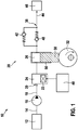
- FIG. 1 shows a fuel system 10 for an internal combustion engine, not shown, in a simplified schematic representation.
- Fuel is supplied from a fuel tank 12 via a suction line 14, by means of a prefeed pump 16 and a low pressure line 18 via an inlet 20 of a quantity control valve 24 which can be actuated by an electromagnetic actuating device 22 to a delivery chamber 26 of a high pressure fuel pump 28.
- the quantity control valve 24 can be an inlet valve of the high-pressure fuel pump 28 that can be positively opened.
- the high-pressure fuel pump 28 is designed as a piston pump, a piston 30 being able to be moved vertically in the drawing by means of a cam disk 32 (“drive”).
- Hydraulically between the delivery chamber 26 and an outlet 36 of the high-pressure fuel pump 28 is in the Figure 1 arranged as a spring-loaded check valve outlet valve 40 which can open towards the outlet 36.
- the outlet 36 is connected to a high-pressure line 44 and via this to a high-pressure accumulator 46 (“common rail”).
- a pressure relief valve 42 which is also drawn as a spring-loaded check valve and which can open toward the delivery chamber 26, is arranged hydraulically between the outlet 36 and the delivery chamber 26.
- the prefeed pump 16 delivers fuel from the fuel tank 12 into the low-pressure line 18.
- the quantity control valve 24 can be closed and opened depending on a particular fuel requirement. As a result, the pumped to the high pressure accumulator 46 Fuel quantity affected.
- the electromagnetic actuating device 22 is controlled by a control and / or regulating device 48.
- FIG. 2 A section of a high-pressure pump 28 is shown, which comprises an approximately cup-shaped seal carrier 68 and a piston spring 70, which is arranged radially on the outside around a section of the seal carrier 68 and is designed as a helical spring and is supported with an end section on the seal carrier 68.
- a spring plate 72, on which an end section of the piston spring 70 is received, is pressed onto an end section of the piston 30 which is lower in the drawing and faces the drive.
- a piston seal Arranged radially inside the seal carrier 68 is a piston seal (also referred to as “low-pressure seal”), which is referred to as a sealing device 74 and radially surrounds the lower second section (which faces the drive) of the piston 30 and one that is present between the housing 50 and the seal carrier 68 Seals fluid space ("step room") to the outside to the engine block 53.
- the piston 30 is displaceable along the longitudinal axis 64 relative to the sealing device 74.
- the sealing device 74 has an overall annular structure.
- the sealing device 74 is shown in FIG Figure 2 axially supported upwards by a holding section 76 arranged inside the seal carrier 68 and also approximately hat-shaped.
- a space area above the sealing device 74 characterizes a "fuel side” and a space area below the sealing device 74 a "oil side”.
- the sealing device 74 is also shown in FIG Figure 2 supported axially downward by a radially inward curved peripheral portion of the seal carrier 68. It goes without saying that the sealing device 74 can optionally have a small axial play within a region determined by the holding section 76 and the said edge section.
- the sealing device 74 is arranged on the piston 30 radially on the outside along the longitudinal axis 64 and is essentially rotationally symmetrical.
- Figure 3 shows part of the substantially radially outwardly extending and also in Figure 2 shown second section 92 and a radially outer edge region 93 which adjoins the second section 90 and has a connecting section 94.
- the connecting section 94 has an angle 96 with respect to the axis of the piston, which, according to a possible embodiment, is approximately 45 °.
- the angle 96 is preferably in ranges between approximately 30 ° to 60 °. It is advantageous if the angle 96 is in a range between 40 ° to 50 ° and very particularly advantageous if the angle 96 is as in FIG Figure 3 shown is approximately 45 °.
- a radius 98 of at least approximately 0.3 mm of the housing 50 meets a surface of the seal carrier 68 or a connecting section 94 which is inclined by the angle 96.
- the more solid component preferably has the radius 98. This reduces the line cross section, so that the solid component, in this case the housing 50 of the high-pressure fuel pump 28, melts similarly early as the thinner-walled component, in this case the seal carrier 68, and a robust weld seam arises.
- a minimum gap 99 of approximately 0.1 mm is maintained between the housing 50 and the edge region 93 of the seal carrier 68.
- Figure 4 shows the same section of the housing 50 of the high pressure fuel pump 28 and the seal carrier 68 as in FIG Figure 3 , but according to another possible embodiment, in which the weld seam is formed by means of a ring boss 100.
- the ring boss 100 is formed on the housing 50 of the high-pressure pump 28 before the welding process.
- the connecting section 94 is here inclined at an angle 101 of approximately 90 ° about the longitudinal axis 64 of the piston 30. This enables a particularly stable weld, but other angles of the connecting section 94 are also possible.
- Figure 5 can be provided to provide on the housing 50 of the high-pressure fuel pump 28 a shoulder 102, on which the capacitor discharge welding takes place, whereby a shortening of the lever arm and a reduction in the load is possible.
- FIG. 7 shows an arrangement with which the capacitor discharge welding process according to the invention can be carried out.
- the housing 50 of the high-pressure fuel pump 28 is arranged on a first electrode 110.
- a substantially annular second electrode 112 is arranged on the connecting section 94 of the seal carrier 68.
- the connecting portion 94 is, for example, as in FIG Figure 3 shown trained.
- the second electrode 112 is preferably designed such that it applies a predeterminable force to the seal carrier 68 or the connecting section 94 in a resilient and / or floating manner.
- Figure 8 shows in a flow chart method steps that are carried out according to a possible embodiment of the method according to the invention in the manufacture of the high-pressure fuel pump 28.
- the method begins in a step 200, in which the housing 50 of the high-pressure fuel pump 28 is positioned on the first electrode 110.
- a step 201 the seal carrier 68 is inserted and prepositioned.
- the second electrode 112 is put on and floating stored. Their own weight is preferably selected such that the force required for the welding process to be carried out later is generated.
- the arrangement is centered in a step 203 and in a step 204 the process parameters, in particular the sinking path, the force and / or the current profile, are monitored when the welding process is carried out.
- a step 205 the capacitor discharge welding takes place, so that the seal carrier 68 in the connecting section 94 is connected to the housing 50 of the high-pressure fuel pump 28 in a cohesive manner.
- a step 206 the process parameters monitored in step 204 are evaluated.
- These output variables of the production are compared with predetermined values in a step 207. If deviations are ascertainable that go beyond a definable tolerance threshold, the manufacturing process of this high-pressure fuel pump 28 is interrupted in a step 209 and it is declared as a reject. If necessary, some parameters are adjusted for the welding process. If the monitored process parameters were within the predefinable tolerance ranges, the method ends in a step 208.
- capacitor discharge welding process shortens the cycle time in the production of the high-pressure fuel pump 28, in particular when the seal carrier 68 is connected to the housing 50 of the high-pressure fuel pump 28. Furthermore, the use of capacitor discharge welding eliminates the need for regular cleaning of the protective glass, which is required, for example, in the laser welding process in order to ensure faultless welding.
- a leaky laser weld seam is not only determined during the end-of-band test during the tightness test carried out there, but rather by evaluating the process parameters, it can be recognized in production whether the welding process was successful.
Landscapes
- Engineering & Computer Science (AREA)
- General Engineering & Computer Science (AREA)
- Mechanical Engineering (AREA)
- Chemical & Material Sciences (AREA)
- Combustion & Propulsion (AREA)
- Fuel-Injection Apparatus (AREA)
- Details Of Reciprocating Pumps (AREA)
Description
- Die Erfindung betrifft eine Kraftstoffpumpe, insbesondere eine Kraftstoffhochdruckpumpe, mit einem Kolben, an dessen einem Antrieb zugewandten Endabschnitt eine den Kolben radial umschließende Dichteinrichtung angeordnet ist.
Die Erfindung betrifft ferner ein Verfahren zum Herstellen einer Kraftstoffpumpe, insbesondere einer Kraftstoffhochdruckpumpe. - In Kraftstoffsystemen von Brennkraftmaschinen werden Kraftstoffpumpen für den Transport von Kraftstoff eingesetzt. Bei Systemen mit Benzindirekteinspritzung werden die Kraftstoffpumpen durch Kraftstoffhochdruckpumpen ergänzt, die den beispielsweise von einer Elektrokraftstoffpumpe mit einem Vordruck gelieferten Kraftstoff in ausreichender Menge auf das für die Benzinhochdruckeinspritzung erforderliche Niveau verdichten.
- Derartige Kraftstoffpumpen weisen üblicherweise mindestens einen Kolben auf, der mittels eines durch eine Nocke oder eine Exzenterscheibe gebildeten Antriebs axial bewegt werden kann. Eine erforderliche Rückstellkraft des Kolbens wird dabei mittels einer Druckfeder erzeugt. Beispielsweise ist ein von einer Druckfeder beaufschlagter Federteller auf einen Endabschnitt des Kolbens aufgepresst. Dabei kann eine radial außen an dem Kolben angeordnete Kolbendichtung einen ersten kraftstoffseitigen Abschnitt des Kolbens von einem zweiten ölseitigen Abschnitt des Kolbens trennen, wodurch eine Vermischung von Kraftstoff und Öl zumindest gering gehalten wird. Eine solche auch als Niederdruckdichtung bezeichnete Kolbendichtung ist üblicherweise von einer Halteeinrichtung gehalten, die auch als Dichtungsträger bezeichnet wird. Der Dichtungsträger ist mit dem Gehäuse der Kraftstoffhochdruckpumpe derart verbunden, dass auch hier eine Abdichtung des ölseitigen Abschnitts der Kraftstoffpumpe von einem kraftstoffseitigen Abschnitt zuverlässig erfolgt, wobei der Dichtungsträger eine statische Dichtung gegen die Niederdruckdichtung und gegen das Gehäuse darstellt.
- Dichtungsträger sind beispielsweise als tiefgezogene Elemente realisiert, die über eine Laserschweißnaht eine stoffschlüssige Verbindung mit dem Gehäuse der Kraftstoffhochdruckpumpe eingehen und dadurch zwischen Öl- und Kraftstoffseite statisch abdichten. Aus
DE 10 2013 205909 A1 ist eine Kraftstoff-Kolbenpumpe mit einer den Kolben radial umschließenden Dichteinrichtung bekannt. AusDE 10 2013 206930 A1 ist zudem die Anwendung des Kondensator-Entladungsschweißverfahrens bei Kraftstoffpumpen bekannt. - Aufgabe der Erfindung ist es, eine Kraftstoffpumpe bereitzustellen, deren Herstellung verbesserte Taktzeiten beim Fügen beziehungsweise Schweißen des Dichtungsträgers ermöglicht und eine verbesserte Fehlererkennung im Herstellungsprozess möglich macht.
- Die Aufgabe wird durch eine Kraftstoffhochdruckpumpe mit einem Kolben, an dessen einem Antrieb zugewandten Endabschnitt eine den Kolben radial umschließende Dichteinrichtung angeordnet ist, wobei die Dichteinrichtung von mindestens einem Dichtungsträger gehalten ist, und wobei der Dichtungsträger mindestens abschnittsweise mit einem Gehäuse der Kraftstoffpumpe verbunden ist, dadurch gelöst, dass der Dichtungsträger mindestens einen radial umlaufenden Abschnitt aufweist, an welchem der Dichtungsträger mit dem Gehäuse mittels Kondensator-Entladungsschweißen stoffschlüssig verbunden ist.
- Das stoffschlüssige Verbinden des Dichtungsträgers mit dem Kraftstoffpumpengehäuse mittels Kondensator-Entladungsschweißen reduziert die Taktzeit bei der Herstellung der Kraftstoffpumpe, da mittels des Kondensator-Entladungsschweißens eine schnellere und präzisere stoffschlüssige Verbindung zwischen dem Dichtungsträger und dem Gehäuse herstellbar ist. Insbesondere entstehen bei dem Kondensator-Entladungsschweißen im Vergleich zum Laserschweißprozess nahezu keine Spritzer und kein Schmauch. Damit entfällt auch die Notwendigkeit einer regelmäßigen Reinigung des Schutzglases, beispielsweise um die Qualität der Schweißung sicherzustellen.
- Eine eventuell auftretende Undichtigkeit einer Schweißnaht, die bei den bisher verwendeten Schweißverfahren, insbesondere dem Laserschweißen, entsteht, kann erst bei der sogenannten Band-Ende-Prüfung während der Dichtheitsuntersuchung festgestellt werden. Durch Anwenden des Kondensator-Entladungsschweißens kann der Schweißprozess bereits in der Produktion überwacht werden. Vorzugsweise werden hier ein sogenannter Absinkweg beziehungsweise Nachsetzweg und/oder der Stromverlauf bei dem Kondensator-Entladungsschweißen überwacht. Dadurch ist es möglich, den Ausschuss deutlich früher zu erkennen, was eine Anpassung des Herstellungsprozesses erleichtert und Fehlerkosten reduziert.
- Gemäß der Erfindung umfasst der Dichtungsträger einen sich im Wesentlichen axial erstreckenden ersten Abschnitt, welcher die Dichteinrichtung radial umschließt, einen an den ersten Abschnitt angrenzenden und sich im Wesentlichen radial nach außen erstreckenden zweiten Abschnitt, und einen an den zweiten Abschnitt angrenzenden radial äußeren Verbindungsabschnitt, der mit dem Gehäuse der Kraftstoffpumpe mittels Kondensator-Entladungsschweißen stoffschlüssig verbunden ist. Der Verbindungsabschnitt des Dichtungsträgers weist in Bezug auf die Achse des Kolbens einen Winkel von in etwa 30° bis 60°, vorzugsweise von in etwa 40° bis 50° auf. Die radiale Erstreckung dieses Verbindungsabschnitts beträgt etwa 2 bis 4 mm, vorzugsweise ca. 3 mm. Mit diesen Ausführungsformen kann bei dem Kondensator-Entladungsschweißen eine Anbindelänge von mindestens ca. 1 mm erreicht werden, wodurch eine robuste und sicher dichtende Schweißnaht entsteht.
- Gemäß einer bevorzugten Ausführungsform ist zwischen dem zweiten Abschnitt des Dichtungsträgers und dem Gehäuse ein Spalt von mindestens etwa 0,1 mm vorhanden. Damit ist sichergestellt, dass kein unerwünschter beziehungsweise undefinierter Nebenschluss bei der Durchführung des Kondensator-Entladungsschweißens auftritt.
- Gemäß einer anderen möglichen Ausführungsform ist der zweite Abschnitt des Dichtungsträgers mittels einer Pressung mit dem Gehäuse der Kraftstoffpumpe verbunden. Bei dieser Ausführungsform ist eine besonders stabile Verbindung zwischen dem Dichtungsträger und dem Gehäuse erreichbar.
- Vorzugsweise ist der Verbindungsabschnitt des Dichtungsträgers an einem radial umlaufenden Absatz des Gehäuses mit dem Gehäuse mittels Kondensator-Entladungsschweißen stoffschlüssig verbunden. Das Vorsehen des radial umlaufenden Absatzes an dem Gehäuse ermöglicht eine verbesserte Herstellung der Kraftstoffpumpe und erhöht die Stabilität der stoffschlüssigen Verbindung.
- Die Aufgabe wird auch durch ein Verfahren zum Herstellen einer Kraftstoffpumpe gelöst, wobei das Verfahren die folgenden Schritte umfasst:
- Anordnen des Gehäuses an einer ersten Elektrode einer Schweißeinrichtung für ein Kondensator-Entladungsschweißen;
- Anordnen des Dichtungsträgers an einem radial inneren Abschnitt des Gehäuses;
- Anordnen einer im Wesentlichen ringförmigen zweiten Elektrode an einem radial umlaufenden Verbindungsabschnitt des Dichtungsträgers, wobei die zweite Elektrode den Dichtungsträger mit einer vorgebbaren Kraft federnd und/oder schwimmend beaufschlagt;
- Justieren und/oder Zentrieren des Dichtungsträgers in dem Gehäuse;
- Durchführen eines Kondensators-Entladungsschweißens zwischen dem Verbindungsabschnitt des Dichtungsträgers und dem Gehäuse.
- Mittels dieses Verfahrens ist eine stoffschlüssige Verbindung zwischen dem Dichtungsträger und dem Gehäuse der Kraftstoffhochdruckpumpe erreichbar, wodurch die oben genannten Vorteile realisiert werden.
- Gemäß einer möglichen Ausführungsform wird der zweite Abschnitt des Dichtungsträgers mittels einer Pressung in einen radial inneren Abschnitt des Gehäuses gepresst und es wird dann an einem Verbindungsabschnitt des Dichtungsträgers das Kondensator-Entladungsschweißen durchgeführt.
- Vorzugsweise werden während des Kondensator-Entladungsschweißens eine Kraft und/oder eine Relativbewegung des Dichtungsträgers zu dem Gehäuse und/oder ein Stromverlauf des Kondensator-Entladungsschweißens ermittelt. Die so ermittelten Werte können herangezogen werden, um die Güte der Schweißverbindung zu bestimmen. Vorzugsweise werden die ermittelten Werte mit gespeicherten Werten für die Kraft, die Relativbewegung und/oder den Stromverlauf verglichen.
- Weitere Merkmale, Anwendungsmöglichkeiten und Vorteile der Erfindung ergeben sich aus der nachfolgenden Beschreibung von Ausführungsbeispielen der Erfindung, die anhand der Zeichnungen erläutert werden.
- Es zeigen:
- Figur 1
- eine vereinfachte schematisierte Darstellung eines Kraftstoffsystems für eine Brennkraftmaschine;
- Figur 2
- einen Ausschnitt eines Längsschnitts durch eine Kraftstoffhochdruckpu mpe;
- Figur 3
- eine axiale Schnittansicht des radial äußeren Randbereichs des Dichtungsträgers sowie eines Abschnitts des Gehäuses der Kraftstoffhochdruckpumpe gemäß einer möglichen Ausführungsform;
- Figur 4
- eine axiale Schnittansicht eines radial äußeren Randbereichs einer Dichteinrichtung sowie eines Abschnitts des Gehäuses einer Hochdruckpumpe gemäß einer anderen möglichen Ausführungsform;
- Figur 5
- eine axiale Schnittansicht eines radial äußeren Randbereichs eines Dichtungsträgers sowie eines Abschnitts eines Gehäuses gemäß einer weiteren möglichen Ausführungsform;
- Figur 6
- eine axiale Schnittansicht eines Dichtungsträgers sowie eines Gehäuses gemäß einer möglichen Ausführungsform;
- Figur 7
- eine schematisierte Darstellung einer Schnittansicht eines Teils der Kraftstoffhochdruckpumpe während der Durchführung des KE-Schweißprozesses; und
- Figur 8
- ein vereinfachtes Flussdiagramm mit bei der Herstellung der Kraftstoffhochdruckpumpe möglichen Verfahrensschritten.
-
Figur 1 zeigt ein Kraftstoffsystem 10 für eine weiter nicht dargestellte Brennkraftmaschine in einer vereinfachten schematischen Darstellung. Aus einem Kraftstofftank 12 wird Kraftstoff über eine Saugleitung 14, mittels einer Vorförderpumpe 16 und einer Niederdruckleitung 18 über einen Einlass 20 eines von einer elektromagnetischen Betätigungseinrichtung 22 betätigbaren Mengensteuerventils 24 einem Förderraum 26 einer Kraftstoff-Hochdruckpumpe 28 zugeführt. Beispielsweise kann das Mengensteuerventil 24 ein zwangsweise öffnenbares Einlassventil der Kraftstoff-Hochdruckpumpe 28 sein. - Vorliegend ist die Kraftstoff-Hochdruckpumpe 28 als Kolbenpumpe ausgeführt, wobei ein Kolben 30 mittels einer Nockenscheibe 32 ("Antrieb") in der Zeichnung vertikal bewegt werden kann. Hydraulisch zwischen dem Förderraum 26 und einem Auslass 36 der Kraftstoff-Hochdruckpumpe 28 ist ein in der
Figur 1 als federbelastetes Rückschlagventil gezeichnetes Auslassventil 40 angeordnet, welches zu dem Auslass 36 hin öffnen kann. Der Auslass 36 ist an eine Hochdruckleitung 44 und über diese an einen Hochdruckspeicher 46 ("Common Rail") angeschlossen. Weiterhin ist hydraulisch zwischen dem Auslass 36 und dem Förderraum 26 ein ebenfalls als federbelastetes Rückschlagventil gezeichnetes Druckbegrenzungsventil 42 angeordnet, welches zum Förderraum 26 hin öffnen kann. - Im Betrieb des Kraftstoffsystems 10 fördert die Vorförderpumpe 16 Kraftstoff vom Kraftstofftank 12 in die Niederdruckleitung 18. Das Mengensteuerventil 24 kann in Abhängigkeit von einem jeweiligen Bedarf an Kraftstoff geschlossen und geöffnet werden. Hierdurch wird die zu dem Hochdruckspeicher 46 geförderte Kraftstoffmenge beeinflusst. Die elektromagnetische Betätigungseinrichtung 22 wird durch eine Steuer- und/oder Regeleinrichtung 48 angesteuert.
- In
Figur 2 ist ein Ausschnitt einer Hochdruckpumpe 28 gezeigt, die einen in etwa topfförmig ausgebildeten Dichtungsträger 68, sowie eine radial außen um einen Abschnitt des Dichtungsträgers 68 angeordnete und als Schraubenfeder ausgeführte Kolbenfeder 70 umfasst, die sich mit einem Endabschnitt an dem Dichtungsträger 68 abstützt. An einem in der Zeichnung unteren und dem Antrieb zugewandten Endabschnitt des Kolbens 30 ist ein Federteller 72 aufgepresst, an welchem ein Endabschnitt der Kolbenfeder 70 aufgenommen ist. - Radial innerhalb des Dichtungsträgers 68 ist eine als Dichteinrichtung 74 bezeichnete Kolbendichtung (auch als "Niederdruckdichtung" bezeichnet) angeordnet, welche den unteren zweiten Abschnitt (welcher dem Antrieb zugewandt ist) des Kolbens 30 radial umschließt und einen zwischen dem Gehäuse 50 und dem Dichtungsträger 68 vorhandenen Fluidraum ("Stufenraum") nach außen zum Motorblock 53 hin abdichtet. Der Kolben 30 ist entlang der Längsachse 64 relativ zu der Dichteinrichtung 74 verschiebbar. In grober Näherung weist die Dichteinrichtung 74 eine insgesamt ringförmige Struktur auf.
- Vorliegend ist die Dichteinrichtung 74 in der
Figur 2 nach oben durch einen innerhalb des Dichtungsträgers 68 angeordneten und ebenfalls in etwa hutförmig ausgebildeten Halteabschnitt 76 axial abgestützt. In der Zeichnung charakterisieren ein Raumbereich oberhalb der Dichteinrichtung 74 eine "Kraftstoffseite" und ein Raumbereich unterhalb der Dichteinrichtung 74 eine "Ölseite". - Weiterhin ist die Dichteinrichtung 74 in der
Figur 2 nach unten durch einen nach radial innen gebogenen umlaufenden Randabschnitt des Dichtungsträgers 68 axial abgestützt. Es versteht sich, dass die Dichteinrichtung 74 innerhalb eines durch den Halteabschnitt 76 und den besagten Randabschnitt bestimmten Bereichs gegebenenfalls ein geringes axiales Spiel aufweisen kann. - Die Dichteinrichtung 74 ist entlang der Längsachse 64 radial außen an dem Kolben 30 angeordnet und im Wesentlichen rotationssymmetrisch ausgeführt.
Figur 3 zeigt einen Teil des sich im Wesentlichen radial nach außen erstreckenden und ebenfalls inFigur 2 gezeigten zweiten Abschnitts 92 sowie einen an den zweiten Abschnitt 90 angrenzenden radial äußeren Randbereich 93, der einen Verbindungsabschnitt 94 aufweist. Gemäß der inFigur 3 gezeigten Ausführungsform weist der Verbindungsabschnitt 94 in Bezug auf die Achse des Kolbens einen Winkel 96 auf, der gemäß einer möglichen Ausführungsform circa 45° beträgt. Vorzugsweise liegt der Winkel 96 in Bereichen zwischen etwa 30° bis 60°. Es ist vorteilhaft, wenn der Winkel 96 in einem Bereich zwischen 40° bis 50° liegt und ganz besonders vorteilhaft, wenn der Winkel 96 wie inFigur 3 gezeigt etwa 45° beträgt. - Um bei der Durchführung des Kondensator-Entladungsschweißprozesses eine Anbindelänge 97 von circa 1 mm zu erreichen, ist es vorteilhaft, wenn ein Radius 98 von mindestens circa 0,3 mm des Gehäuses 50 auf eine Fläche des Dichtungsträgers 68 bzw. einen Verbindungsabschnitt 94 trifft, der um den Winkel 96 geneigt ist. Vorzugsweise hat das massivere Bauteil den Radius 98. Dadurch wird der Leitungsquerschnitt reduziert, so dass das massive Bauteil, in diesem Fall das Gehäuse 50 der Kraftstoffhochdruckpumpe 28, ähnlich früh wie das dünnwandigere Bauteil, in diesem Fall der Dichtungsträger 68, aufschmilzt und eine robuste Schweißnaht entsteht. Um einen ungewünschten beziehungsweise undefinierten Nebenschluss beim Schweißprozess zu vermeiden, wird gemäß der in
Figur 3 gezeigten Ausführungsform ein Mindestspalt 99 von circa 0,1 mm zwischen dem Gehäuse 50 und dem Randbereich 93 des Dichtungsträgers 68 vorgehalten. -
Figur 4 zeigt den gleichen Abschnitt des Gehäuses 50 der Kraftstoffhochdruckpumpe 28 und des Dichtungsträgers 68 wie inFigur 3 , jedoch gemäß einer anderen möglichen Ausführungsform, bei dem die Schweißnaht vermittels eines Ringbuckels 100 gebildet wird. Der Ringbuckel 100 ist vor dem Schweißprozess an dem Gehäuse 50 der Hochdruckpumpe 28 ausgebildet. Der Verbindungsabschnitt 94 ist hier in einem Winkel 101 von circa 90° um die Längsachse 64 des Kolbens 30 geneigt. Dies ermöglicht eine besonders stabile Schweißung, jedoch sind auch andere Winkel des Verbindungsabschnitts 94 möglich. - Gemäß einer anderen möglichen Ausführungsform kann wie in
Figur 5 gezeigt vorgesehen sein, an dem Gehäuse 50 der Kraftstoffhochdruckpumpe 28 einen Absatz 102 vorzusehen, an welchem die Kondensator-Entladungschweißung erfolgt, wodurch eine Verkürzung des Hebelarms und eine Reduzierung der Belastung möglich ist. - In
Figur 6 ist ein weiteres mögliches Ausführungsbeispiel gezeigt, bei welchem der radial äußere Randbereich 93 an das Gehäuse 50 der Kraftstoffhochdruckpumpe 28 zusätzlich gepresst ist, wodurch eine nochmals stabilere Verbindung möglich ist. Selbstverständlich muss die vergrößerte Kontaktfläche bei der Durchführung des Kondensator-Entladungsschweißprozesses berücksichtigt werden. -
Figur 7 zeigt eine Anordnung, mit welcher der erfindungsgemäße Kondensator-Entladungsschweißprozess durchführbar ist. Hierzu ist das Gehäuse 50 der Kraftstoffhochdruckpumpe 28 an einer ersten Elektrode 110 angeordnet. Eine im Wesentlichen ringförmige zweite Elektrode 112 ist an dem Verbindungsabschnitt 94 des Dichtungsträgers 68 angeordnet. Der Verbindungsabschnitt 94 ist beispielsweise so wie inFigur 3 gezeigt ausgebildet. Vorzugsweise ist die zweite Elektrode 112 derart ausgeführt, dass sie den Dichtungsträger 68 beziehungsweise den Verbindungsabschnitt 94 mit einer vorgebbaren Kraft federnd und/oder schwimmend beaufschlagt. Nach dem Justieren und/oder Zentrieren des Dichtungsträgers 68 in dem Gehäuse 50 wird das Kondensator-Entladungsschweißen durchgeführt, so dass sich eine Schweißnaht zwischen dem Verbindungsabschnitt 94 und dem dort anliegenden Teil des Gehäuses 50 bildet. -
Figur 8 zeigt in einem Ablaufdiagramm Verfahrensschritte, die gemäß einer möglichen Ausführungsform des erfindungsgemäßen Verfahrens bei der Herstellung der Kraftstoffhochdruckpumpe 28 durchgeführt werden. - Das Verfahren beginnt in einem Schritt 200, in welchem das Gehäuse 50 der Kraftstoffhochdruckpumpe 28 auf der ersten Elektrode 110 positioniert wird. In einem Schritt 201 wird der Dichtungsträger 68 eingelegt und vorpositioniert. In einem Schritt 202 wird die zweite Elektrode 112 aufgesetzt und schwimmend gelagert. Vorzugsweise ist ihr Eigengewicht derart gewählt, dass die für den später durchzuführenden Schweißprozess notwendige Kraft erzeugt wird.
- In einem Schritt 203 wird die Anordnung zentriert und in einem Schritt 204 startet die Überwachung der Prozessparameter, insbesondere des Absinkwegs, der Kraft und/oder des Stromverlaufs bei der Durchführung des Schweißprozesses.
- In einem Schritt 205 erfolgt das Kondensator-Entladungsschweißen, so dass der Dichtungsträger 68 in dem Verbindungsabschnitt 94 mit dem Gehäuse 50 der Kraftstoffhochdruckpumpe 28 stoffschlüssig verbunden wird.
- In einem Schritt 206 werden die in dem Schritt 204 überwachten Prozessparameter ausgewertet. Besonders aussagekräftig sind hier der auch als Nachsetzweg bezeichnete Absinkweg der zweiten Elektrode 112 sowie der Stromverlauf bei der Durchführung des Kondensator-Entladungsschweißens. Diese Ausgabegrößen der Produktion werden mit vorgegebenen Werten in einem Schritt 207 verglichen. Sind Abweichungen feststellbar, die über eine festlegbare Toleranzschwelle gehen, so wird in einem Schritt 209 der Herstellungsprozess dieser Kraftstoffhochdruckpumpe 28 unterbrochen und sie wird als Ausschuss deklariert. Gegebenenfalls erfolgt eine Anpassung einiger Parameter für den Schweißvorgang. Waren die überwachten Prozessparameter innerhalb der vorgebbaren Toleranzbereiche, so endet das Verfahren in einem Schritt 208.
- Dadurch, dass die Ausgabeparameter direkt auf Fehler untersucht werden können, wird der Ausschuss deutlich früher erkannt, was einen korrigierenden Eingriff erheblich erleichtert und Fehlerkosten spart.
- Durch den Einsatz des Kondensator-Entladungsschweißprozesses wird die Taktzeit bei der Herstellung der Kraftstoffhochdruckpumpe 28 insbesondere bei der stoffschlüssigen Verbindung des Dichtungsträgers 68 mit dem Gehäuse 50 der Kraftstoffhochdruckpumpe 28 verkürzt. Ferner entfällt durch den Einsatz des Kondensator-Entladungsschweißens die Notwendigkeit einer regelmäßigen Reinigung des Schutzglases, das beispielsweise beim Laserschweißprozess benötigt wird, um eine fehlerfreie Schweißung sicherzustellen.
- Mit dem erfindungsgemäßen Verfahren wird eine undichte Laserschweißnaht nicht erst bei der Band-Ende-Prüfung während der dort durchgeführten Dichtheitsuntersuchung festgestellt, sondern durch die Auswertung der Prozessparameter kann bereits in der Produktion erkannt werden, ob der Schweißvorgang erfolgreich war.
Claims (8)
- Kraftstoffpumpe, insbesondere Kraftstoffhochdruckpumpe (28), mit mindestens einem Kolben (30), an dem eine den Kolben (30) radial umschließende Dichteinrichtung (74) angeordnet ist, wobei die Dichteinrichtung (74) einen Dichtungsträger (68) umfasst und wobei der Dichtungsträger (68) mindestens abschnittsweise mit einem Gehäuse (50) der Kraftstoffpumpe verbunden ist, wobei der Dichtungsträger (68) mindestens einen radial umlaufenden Abschnitt (92, 94) aufweist, an welchem der Dichtungsträger (68) mit dem Gehäuse (50) stoffschlüssig verbunden ist;
wobei der Dichtungsträger (68) umfasst:- einen sich im Wesentlichen axial erstreckenden ersten Abschnitt (90), welcher die Dichteinrichtung (74) radial umschließt,- einen an den ersten Abschnitt (90) angrenzenden und sich im Wesentlichen radial nach außen erstreckenden zweiten Abschnitt (92),- und einen an den zweiten Abschnitt (92) angrenzenden radial äußeren Randbereich (93), der mit dem Gehäuse (50) der Kraftstoffpumpe stoffschlüssig verbunden ist;wobei der Randbereich (93) des Dichtungsträgers (68) einen Verbindungsabschnitt (94) aufweist und der Verbindungsabschnitt (94) in Bezug auf die Achse (64) des Kolbens (30) einen Winkel von in etwa 30° bis 60°, bevorzugt von in etwa 40° bis 50°, sowie eine radiale Erstreckung von in etwa 2 Millimeter bis 4 Millimeter aufweist und wobei der Verbindungsabschnitt (94) mit dem Gehäuse (50) der Kraftstoffpumpe mittels Kondensator-Entladungsschweißen stoffschlüssig verbunden ist. - Kraftstoffpumpe, insbesondere Kraftstoffhochdruckpumpe (28), mit mindestens einem Kolben (30), an dem eine den Kolben (30) radial umschließende Dichteinrichtung (74) angeordnet ist, wobei die Dichteinrichtung (74) einen Dichtungsträger (68) umfasst und wobei der Dichtungsträger (68) mindestens abschnittsweise mit einem Gehäuse (50) der Kraftstoffpumpe verbunden ist, wobei der Dichtungsträger (68) mindestens einen radial umlaufenden Abschnitt (92, 94) aufweist, an welchem der Dichtungsträger (68) mit dem Gehäuse (50) stoffschlüssig verbunden ist;
wobei der Dichtungsträger (68) umfasst:- einen sich im Wesentlichen axial erstreckenden ersten Abschnitt (90), welcher die Dichteinrichtung (74) radial umschließt,- einen an den ersten Abschnitt (90) angrenzenden und sich im Wesentlichen radial nach außen erstreckenden zweiten Abschnitt (92),- und einen an den zweiten Abschnitt (92) angrenzenden radial äußeren Randbereich (93), der mit dem Gehäuse (50) der Kraftstoffpumpe stoffschlüssig verbunden ist;wobei der Randbereich (93) des Dichtungsträgers (68) einen Verbindungsabschnitt (94) aufweist und der Verbindungsabschnitt (94) in Bezug auf die Achse (64) des Kolbens (30) einen Winkel von in etwa 100° bis 80°, bevorzugt von in etwa 90° aufweist und wobei an dem Gehäuse (50) ein Ringbuckel (100) ausgebildet ist und der Verbindungsabschnitt (94) vermittels des Ringbuckels (100) mit dem Gehäuse (50) der Kraftstoffpumpe mittels Kondensator-Entladungsschweißen stoffschlüssig verbunden ist. - Kraftstoffpumpe nach einem der Ansprüche 1 oder 2, wobei zwischen dem Randbereich (93) des Dichtungsträgers (68) und dem Gehäuse (50) ein radialer Spalt (99) von mindestens etwa 0,1 Millimeter gebildet ist.
- Kraftstoffpumpe nach einem der Ansprüche 1 bis 3, wobei der Dichtungsträger (68) an dem Randbereich (93) mittels einer Pressung mit dem Gehäuse (50) der Kraftstoffpumpe verbunden ist.
- Kraftstoffpumpe nach einem der vorhergehenden Ansprüche 1 bis 4, wobei der Verbindungsabschnitt (94) des Dichtungsträgers (68) an einem radial umlaufenden Absatz (102) des Gehäuses (50) mit dem Gehäuse (50) stoffschlüssig verbunden ist.
- Verfahren zum Herstellen einer Kraftstoffhochdruckpumpe (28) nach einem der vorhergehenden Ansprüche, gekennzeichnet durch die folgenden Schritte:- Anordnen des Gehäuses (50) an einer ersten Elektrode (110) einer Schweißeinrichtung für ein Kondensator-Entladungsschweißen;- Anordnen des Dichtungsträgers (68) an einem radial inneren Abschnitt des Gehäuses (50);- Anordnen einer im Wesentlichen ringförmigen zweiten Elektrode (112) an einem radial umlaufenden Verbindungsabschnitt (94) des Dichtungsträgers (68), wobei die zweite Elektrode den Dichtungsträger (68) mit einer vorgebbaren Kraft federnd und/oder schwimmend beaufschlagt;- Justieren und/oder Zentrieren des Dichtungsträgers (68) in dem Gehäuse (50);- Durchführen eines Kondensator-Entladungsschweißens zwischen dem radial umlaufenden Verbindungsabschnitt (94) des Dichtungsträgers (68) und dem Gehäuse (50).
- Verfahren nach Anspruch 6, wobei der Randbereich (93) des Dichtungsträgers (68) eine Pressung an einen radial inneren Abschnitt des Gehäuses (50) durchgeführt wird und an einem sich dem Randbereich (93) anschließenden Verbindungsabschnitt (94) des Dichtungsträgers (68) das Kondensator-Entladungsschweißen durchgeführt wird.
- Verfahren nach einem der Ansprüche 6 oder 7, wobei während des Kondensator-Entladungsschweißens eine Kraft und/oder eine Relativbewegung des Dichtungsträgers (68) zu dem Gehäuse (50) und/oder ein Stromverlauf des Kondensator-Entladungsschweißens ermittelt wird, und wobei die ermittelte Kraft und/oder die ermittelte Relativbewegung und/oder der ermittelte Stromverlauf mit gespeicherten Werten für die Kraft und/oder die Relativbewegung und/oder den Stromverlauf verglichen werden, und wobei in Abhängigkeit von dem Vergleich eine Güte der Schweißverbindung ermittelt wird.
Applications Claiming Priority (2)
| Application Number | Priority Date | Filing Date | Title |
|---|---|---|---|
| DE102015209539.8A DE102015209539A1 (de) | 2015-05-22 | 2015-05-22 | Kraftstoffhochdruckpumpe |
| PCT/EP2016/057572 WO2016188661A1 (de) | 2015-05-22 | 2016-04-07 | Kraftstoffhochdruckpumpe |
Publications (2)
| Publication Number | Publication Date |
|---|---|
| EP3298263A1 EP3298263A1 (de) | 2018-03-28 |
| EP3298263B1 true EP3298263B1 (de) | 2020-06-10 |
Family
ID=55697196
Family Applications (1)
| Application Number | Title | Priority Date | Filing Date |
|---|---|---|---|
| EP16714902.0A Active EP3298263B1 (de) | 2015-05-22 | 2016-04-07 | Kraftstoffhochdruckpumpe |
Country Status (7)
| Country | Link |
|---|---|
| US (1) | US10662940B2 (de) |
| EP (1) | EP3298263B1 (de) |
| JP (1) | JP6516877B2 (de) |
| KR (1) | KR102556113B1 (de) |
| CN (1) | CN107646074B (de) |
| DE (1) | DE102015209539A1 (de) |
| WO (1) | WO2016188661A1 (de) |
Families Citing this family (6)
| Publication number | Priority date | Publication date | Assignee | Title |
|---|---|---|---|---|
| JP7139442B2 (ja) * | 2018-10-19 | 2022-09-20 | 日立Astemo株式会社 | 高圧燃料ポンプ |
| KR102107462B1 (ko) * | 2018-12-14 | 2020-05-07 | 주식회사 현대케피코 | 고압펌프의 패킹캐리어 변형 방지 구조 |
| DE102020208202A1 (de) | 2020-07-01 | 2022-01-05 | Robert Bosch Gesellschaft mit beschränkter Haftung | Kraftstoff-Hochdruckpumpe |
| DE102020208849A1 (de) | 2020-07-15 | 2022-01-20 | Robert Bosch Gesellschaft mit beschränkter Haftung | Kraftstoffpumpe, insbesondere Kraftstoff-Hochdruckpumpe |
| DE102021202359A1 (de) * | 2021-03-11 | 2022-09-15 | Robert Bosch Gesellschaft mit beschränkter Haftung | Kraftstoff-Hochdruckpumpe |
| DE102021208296A1 (de) | 2021-07-30 | 2023-02-02 | Robert Bosch Gesellschaft mit beschränkter Haftung | Kolbenpumpe, insbesondere Kraftstoff-Hochdruckpumpe |
Family Cites Families (12)
| Publication number | Priority date | Publication date | Assignee | Title |
|---|---|---|---|---|
| JPS56134413U (de) * | 1981-02-27 | 1981-10-12 | ||
| JPH0666872U (ja) * | 1993-02-19 | 1994-09-20 | 川崎製鉄株式会社 | 積層金属板へ溶接するスタッドの形状 |
| DE10322598A1 (de) * | 2003-05-20 | 2004-12-09 | Robert Bosch Gmbh | Kolbenpumpe, insbesondere Hochdruck-Kraftstoffpumpe |
| DE102004063075B4 (de) * | 2004-12-28 | 2015-11-26 | Robert Bosch Gmbh | Kraftstoff-Hochdruckpumpe für eine Brennkraftmaschine mit einem Stufenkolben und einem Mengensteuerventil |
| DE102007012704A1 (de) * | 2007-03-16 | 2008-09-18 | Robert Bosch Gmbh | Hochdruckpumpe zur Förderung von Kraftstoff mit einer verbesserten Ausbildung der Lageranordnung zur Lagerung der Nockenwelle |
| DE102007038984A1 (de) * | 2007-08-17 | 2009-02-19 | Robert Bosch Gmbh | Kraftstoffpumpe für ein Kraftstoffsystem einer Brennkraftmaschine |
| JP5039507B2 (ja) * | 2007-10-31 | 2012-10-03 | 日立オートモティブシステムズ株式会社 | 高圧燃料供給ポンプおよびその製造方法 |
| IT1396142B1 (it) * | 2009-11-03 | 2012-11-16 | Magneti Marelli Spa | Pompa carburante con dispositivo smorzatore perfezionato per un sistema di iniezione diretta |
| IT1396143B1 (it) * | 2009-11-03 | 2012-11-16 | Magneti Marelli Spa | Pompa carburante con ridotta usura di una guarnizione per un sistema di iniezione diretta |
| JP5812684B2 (ja) * | 2011-05-20 | 2015-11-17 | 日本ドライブイット株式会社 | コンデンサ放電型スタッド溶接機の溶接良否判定方法及び判定装置 |
| DE102013205909A1 (de) * | 2013-04-04 | 2014-10-09 | Robert Bosch Gmbh | Kraftstoff-Kolbensteckpumpe mit einem Gehäuse, mindestens einem in dem Gehäuse angeordneten axial bewegbaren Kolben, und einem Koppelabschnitt |
| DE102013206930A1 (de) * | 2013-04-17 | 2014-10-23 | Robert Bosch Gmbh | Kolbenpumpe, insbesondere Kraftstoff-Hochdruckpumpe |
-
2015
- 2015-05-22 DE DE102015209539.8A patent/DE102015209539A1/de not_active Withdrawn
-
2016
- 2016-04-07 EP EP16714902.0A patent/EP3298263B1/de active Active
- 2016-04-07 KR KR1020177033492A patent/KR102556113B1/ko active Active
- 2016-04-07 WO PCT/EP2016/057572 patent/WO2016188661A1/de not_active Ceased
- 2016-04-07 US US15/576,160 patent/US10662940B2/en active Active
- 2016-04-07 CN CN201680029786.7A patent/CN107646074B/zh active Active
- 2016-04-07 JP JP2017560805A patent/JP6516877B2/ja active Active
Also Published As
| Publication number | Publication date |
|---|---|
| US20180135619A1 (en) | 2018-05-17 |
| EP3298263A1 (de) | 2018-03-28 |
| JP2018514702A (ja) | 2018-06-07 |
| US10662940B2 (en) | 2020-05-26 |
| WO2016188661A1 (de) | 2016-12-01 |
| KR102556113B1 (ko) | 2023-07-18 |
| CN107646074A (zh) | 2018-01-30 |
| CN107646074B (zh) | 2020-05-19 |
| KR20180009749A (ko) | 2018-01-29 |
| JP6516877B2 (ja) | 2019-05-22 |
| DE102015209539A1 (de) | 2016-11-24 |
Similar Documents
| Publication | Publication Date | Title |
|---|---|---|
| EP3298263A1 (de) | Kraftstoffhochdruckpumpe | |
| EP3230579B1 (de) | Kraftstoff-hochdruckpumpe mit einem kolben | |
| DE19808894C2 (de) | Verfahren zum Erhöhen der Ermüdungsfestigkeit aufgrund wiederholten Druckes an einem Abzweigloch in einem Bauteil für Flüssigkeit unter hohem Druck, Abzweiglochteil eines Bauteiles für Flüssigkeit unter hohem Druck, erzeugt durch das Verfahren, und Bauteil für Flüssigkeiten unter hohem Druck mit eingebautem Schieber, welcher das Abzweigloch aufweist | |
| EP3071828B1 (de) | Anordnung, insbesondere für ein kraftstofffördersystem, und verfahren zu deren herstellung | |
| EP1774217B1 (de) | Verbindung von leitungen für hochdruckmedien | |
| DE102013203141A1 (de) | Hochdruckpumpe und Verfahren zur Herstellung einer Hochdruckpumpe | |
| DE112015000312T5 (de) | Verfahren zum Reparieren eines Zylinderblocks mit Wasserdurchgang | |
| DE102008008435A1 (de) | Federbelastetes Ventil und Verfahren zur Einstellung einer Ventilbaugruppe eines federbelasteten Ventils | |
| DE102019206037B4 (de) | Anordnung für ein Einlassventil, Verfahren zum Herstellen einer Anordnung für ein Einlassventil und Kraftstoffhochdruckpumpe für ein Kraftfahrzeug | |
| WO2016184599A1 (de) | Hochdruckanschlussvorrichtung, kraftstoffhochdruckpumpe und verfahren zum herstellen einer hochdruckanschlussvorrichtung für eine kraftstoffhochdruckpumpe | |
| DE10322595A1 (de) | Kolbenpumpe, sowie Verfahren zu ihrer Herstellung | |
| WO2022048967A1 (de) | VORRICHTUNG UND VERFAHREN ZUM VERSCHWEIßEN EINES TOPFFÖRMIGEN GEHÄUSEDECKELS AUF EINEN GEHÄUSEKÖRPER EINER KRAFTSTOFF-HOCHDRUCKPUMPE | |
| EP3482062B1 (de) | Verfahren zur herstellung einer kraftstoffhochdruckpumpe | |
| DE102019204995B4 (de) | Pumpe für ein Kraftfahrzeug und Verfahren zum Herstellen einer Pumpe | |
| DE102014211609A1 (de) | Kraftstoff-Hochdruckpumpe mit einem Kolben | |
| WO2017220240A1 (de) | Hochdruck-kraftstoffpumpe mit einem gehäuse und verfahren zum bearbeiten von kanälen eines gehäuses einer hochdruck-kraftstoffpumpe | |
| DE102013206020A1 (de) | Saugventil für eine Hochdruckpumpe sowie Hochdruckpumpe | |
| DE102008040777A1 (de) | Schweißnaht, Bauteil, Bauteilanordnung sowie Verfahren zum Herstellen einer Schweißnaht | |
| DE102015217969A1 (de) | Fluidelement mit einer Niederdruck-Anschlusseinheit sowie Verfahren zur Herstellung einer Niederdruck-Anschlusseinheit | |
| DE102017204058B3 (de) | Verfahren zur Herstellung einer Kraftstoffhochdruckpumpe sowie Kraftstoffhochdruckpumpe | |
| DE102020215451A1 (de) | Kraftstoff-Hochdruckpumpe sowie Verfahren zum Herstellen einer Kraftstoff-Hochdruckpumpe | |
| DE102018206312A1 (de) | Dichteinrichtung für eine Kraftstoff-Hochdruckpumpe mit einem Kolben | |
| EP3327278A1 (de) | Injektoraufnahme und verbindungsanordnung eines kraftstoffeinspritzsystems | |
| DE102013210021A1 (de) | Hochdruckpumpe für ein Kraftstoffeinspritzsystem mit einem Saugventil | |
| DE102014214291A1 (de) | Kraftstoffhochdruckpumpe, insbesondere Steckpumpe |
Legal Events
| Date | Code | Title | Description |
|---|---|---|---|
| STAA | Information on the status of an ep patent application or granted ep patent |
Free format text: STATUS: THE INTERNATIONAL PUBLICATION HAS BEEN MADE |
|
| PUAI | Public reference made under article 153(3) epc to a published international application that has entered the european phase |
Free format text: ORIGINAL CODE: 0009012 |
|
| STAA | Information on the status of an ep patent application or granted ep patent |
Free format text: STATUS: REQUEST FOR EXAMINATION WAS MADE |
|
| 17P | Request for examination filed |
Effective date: 20171222 |
|
| AK | Designated contracting states |
Kind code of ref document: A1 Designated state(s): AL AT BE BG CH CY CZ DE DK EE ES FI FR GB GR HR HU IE IS IT LI LT LU LV MC MK MT NL NO PL PT RO RS SE SI SK SM TR |
|
| AX | Request for extension of the european patent |
Extension state: BA ME |
|
| DAV | Request for validation of the european patent (deleted) | ||
| DAX | Request for extension of the european patent (deleted) | ||
| GRAP | Despatch of communication of intention to grant a patent |
Free format text: ORIGINAL CODE: EPIDOSNIGR1 |
|
| STAA | Information on the status of an ep patent application or granted ep patent |
Free format text: STATUS: GRANT OF PATENT IS INTENDED |
|
| INTG | Intention to grant announced |
Effective date: 20200130 |
|
| RAP1 | Party data changed (applicant data changed or rights of an application transferred) |
Owner name: ROBERT BOSCH GMBH |
|
| GRAS | Grant fee paid |
Free format text: ORIGINAL CODE: EPIDOSNIGR3 |
|
| GRAA | (expected) grant |
Free format text: ORIGINAL CODE: 0009210 |
|
| STAA | Information on the status of an ep patent application or granted ep patent |
Free format text: STATUS: THE PATENT HAS BEEN GRANTED |
|
| AK | Designated contracting states |
Kind code of ref document: B1 Designated state(s): AL AT BE BG CH CY CZ DE DK EE ES FI FR GB GR HR HU IE IS IT LI LT LU LV MC MK MT NL NO PL PT RO RS SE SI SK SM TR |
|
| REG | Reference to a national code |
Ref country code: GB Ref legal event code: FG4D Free format text: NOT ENGLISH |
|
| REG | Reference to a national code |
Ref country code: CH Ref legal event code: EP Ref country code: AT Ref legal event code: REF Ref document number: 1279389 Country of ref document: AT Kind code of ref document: T Effective date: 20200615 |
|
| REG | Reference to a national code |
Ref country code: DE Ref legal event code: R096 Ref document number: 502016010184 Country of ref document: DE |
|
| REG | Reference to a national code |
Ref country code: IE Ref legal event code: FG4D Free format text: LANGUAGE OF EP DOCUMENT: GERMAN |
|
| REG | Reference to a national code |
Ref country code: LT Ref legal event code: MG4D |
|
| PG25 | Lapsed in a contracting state [announced via postgrant information from national office to epo] |
Ref country code: GR Free format text: LAPSE BECAUSE OF FAILURE TO SUBMIT A TRANSLATION OF THE DESCRIPTION OR TO PAY THE FEE WITHIN THE PRESCRIBED TIME-LIMIT Effective date: 20200911 Ref country code: LT Free format text: LAPSE BECAUSE OF FAILURE TO SUBMIT A TRANSLATION OF THE DESCRIPTION OR TO PAY THE FEE WITHIN THE PRESCRIBED TIME-LIMIT Effective date: 20200610 Ref country code: SE Free format text: LAPSE BECAUSE OF FAILURE TO SUBMIT A TRANSLATION OF THE DESCRIPTION OR TO PAY THE FEE WITHIN THE PRESCRIBED TIME-LIMIT Effective date: 20200610 Ref country code: NO Free format text: LAPSE BECAUSE OF FAILURE TO SUBMIT A TRANSLATION OF THE DESCRIPTION OR TO PAY THE FEE WITHIN THE PRESCRIBED TIME-LIMIT Effective date: 20200910 Ref country code: FI Free format text: LAPSE BECAUSE OF FAILURE TO SUBMIT A TRANSLATION OF THE DESCRIPTION OR TO PAY THE FEE WITHIN THE PRESCRIBED TIME-LIMIT Effective date: 20200610 |
|
| REG | Reference to a national code |
Ref country code: NL Ref legal event code: MP Effective date: 20200610 |
|
| PG25 | Lapsed in a contracting state [announced via postgrant information from national office to epo] |
Ref country code: BG Free format text: LAPSE BECAUSE OF FAILURE TO SUBMIT A TRANSLATION OF THE DESCRIPTION OR TO PAY THE FEE WITHIN THE PRESCRIBED TIME-LIMIT Effective date: 20200910 Ref country code: HR Free format text: LAPSE BECAUSE OF FAILURE TO SUBMIT A TRANSLATION OF THE DESCRIPTION OR TO PAY THE FEE WITHIN THE PRESCRIBED TIME-LIMIT Effective date: 20200610 Ref country code: RS Free format text: LAPSE BECAUSE OF FAILURE TO SUBMIT A TRANSLATION OF THE DESCRIPTION OR TO PAY THE FEE WITHIN THE PRESCRIBED TIME-LIMIT Effective date: 20200610 Ref country code: LV Free format text: LAPSE BECAUSE OF FAILURE TO SUBMIT A TRANSLATION OF THE DESCRIPTION OR TO PAY THE FEE WITHIN THE PRESCRIBED TIME-LIMIT Effective date: 20200610 |
|
| PG25 | Lapsed in a contracting state [announced via postgrant information from national office to epo] |
Ref country code: AL Free format text: LAPSE BECAUSE OF FAILURE TO SUBMIT A TRANSLATION OF THE DESCRIPTION OR TO PAY THE FEE WITHIN THE PRESCRIBED TIME-LIMIT Effective date: 20200610 Ref country code: NL Free format text: LAPSE BECAUSE OF FAILURE TO SUBMIT A TRANSLATION OF THE DESCRIPTION OR TO PAY THE FEE WITHIN THE PRESCRIBED TIME-LIMIT Effective date: 20200610 |
|
| PG25 | Lapsed in a contracting state [announced via postgrant information from national office to epo] |
Ref country code: PT Free format text: LAPSE BECAUSE OF FAILURE TO SUBMIT A TRANSLATION OF THE DESCRIPTION OR TO PAY THE FEE WITHIN THE PRESCRIBED TIME-LIMIT Effective date: 20201012 Ref country code: CZ Free format text: LAPSE BECAUSE OF FAILURE TO SUBMIT A TRANSLATION OF THE DESCRIPTION OR TO PAY THE FEE WITHIN THE PRESCRIBED TIME-LIMIT Effective date: 20200610 Ref country code: ES Free format text: LAPSE BECAUSE OF FAILURE TO SUBMIT A TRANSLATION OF THE DESCRIPTION OR TO PAY THE FEE WITHIN THE PRESCRIBED TIME-LIMIT Effective date: 20200610 Ref country code: RO Free format text: LAPSE BECAUSE OF FAILURE TO SUBMIT A TRANSLATION OF THE DESCRIPTION OR TO PAY THE FEE WITHIN THE PRESCRIBED TIME-LIMIT Effective date: 20200610 Ref country code: SM Free format text: LAPSE BECAUSE OF FAILURE TO SUBMIT A TRANSLATION OF THE DESCRIPTION OR TO PAY THE FEE WITHIN THE PRESCRIBED TIME-LIMIT Effective date: 20200610 Ref country code: EE Free format text: LAPSE BECAUSE OF FAILURE TO SUBMIT A TRANSLATION OF THE DESCRIPTION OR TO PAY THE FEE WITHIN THE PRESCRIBED TIME-LIMIT Effective date: 20200610 |
|
| PG25 | Lapsed in a contracting state [announced via postgrant information from national office to epo] |
Ref country code: SK Free format text: LAPSE BECAUSE OF FAILURE TO SUBMIT A TRANSLATION OF THE DESCRIPTION OR TO PAY THE FEE WITHIN THE PRESCRIBED TIME-LIMIT Effective date: 20200610 Ref country code: PL Free format text: LAPSE BECAUSE OF FAILURE TO SUBMIT A TRANSLATION OF THE DESCRIPTION OR TO PAY THE FEE WITHIN THE PRESCRIBED TIME-LIMIT Effective date: 20200610 Ref country code: IS Free format text: LAPSE BECAUSE OF FAILURE TO SUBMIT A TRANSLATION OF THE DESCRIPTION OR TO PAY THE FEE WITHIN THE PRESCRIBED TIME-LIMIT Effective date: 20201010 |
|
| REG | Reference to a national code |
Ref country code: DE Ref legal event code: R097 Ref document number: 502016010184 Country of ref document: DE |
|
| PLBE | No opposition filed within time limit |
Free format text: ORIGINAL CODE: 0009261 |
|
| STAA | Information on the status of an ep patent application or granted ep patent |
Free format text: STATUS: NO OPPOSITION FILED WITHIN TIME LIMIT |
|
| PG25 | Lapsed in a contracting state [announced via postgrant information from national office to epo] |
Ref country code: DK Free format text: LAPSE BECAUSE OF FAILURE TO SUBMIT A TRANSLATION OF THE DESCRIPTION OR TO PAY THE FEE WITHIN THE PRESCRIBED TIME-LIMIT Effective date: 20200610 |
|
| 26N | No opposition filed |
Effective date: 20210311 |
|
| PG25 | Lapsed in a contracting state [announced via postgrant information from national office to epo] |
Ref country code: SI Free format text: LAPSE BECAUSE OF FAILURE TO SUBMIT A TRANSLATION OF THE DESCRIPTION OR TO PAY THE FEE WITHIN THE PRESCRIBED TIME-LIMIT Effective date: 20200610 |
|
| PG25 | Lapsed in a contracting state [announced via postgrant information from national office to epo] |
Ref country code: MC Free format text: LAPSE BECAUSE OF FAILURE TO SUBMIT A TRANSLATION OF THE DESCRIPTION OR TO PAY THE FEE WITHIN THE PRESCRIBED TIME-LIMIT Effective date: 20200610 |
|
| PG25 | Lapsed in a contracting state [announced via postgrant information from national office to epo] |
Ref country code: LU Free format text: LAPSE BECAUSE OF NON-PAYMENT OF DUE FEES Effective date: 20210407 |
|
| REG | Reference to a national code |
Ref country code: BE Ref legal event code: MM Effective date: 20210430 |
|
| PG25 | Lapsed in a contracting state [announced via postgrant information from national office to epo] |
Ref country code: LI Free format text: LAPSE BECAUSE OF NON-PAYMENT OF DUE FEES Effective date: 20210430 Ref country code: CH Free format text: LAPSE BECAUSE OF NON-PAYMENT OF DUE FEES Effective date: 20210430 |
|
| PG25 | Lapsed in a contracting state [announced via postgrant information from national office to epo] |
Ref country code: IE Free format text: LAPSE BECAUSE OF NON-PAYMENT OF DUE FEES Effective date: 20210407 |
|
| PG25 | Lapsed in a contracting state [announced via postgrant information from national office to epo] |
Ref country code: IS Free format text: LAPSE BECAUSE OF FAILURE TO SUBMIT A TRANSLATION OF THE DESCRIPTION OR TO PAY THE FEE WITHIN THE PRESCRIBED TIME-LIMIT Effective date: 20201010 |
|
| REG | Reference to a national code |
Ref country code: AT Ref legal event code: MM01 Ref document number: 1279389 Country of ref document: AT Kind code of ref document: T Effective date: 20210407 |
|
| PG25 | Lapsed in a contracting state [announced via postgrant information from national office to epo] |
Ref country code: BE Free format text: LAPSE BECAUSE OF NON-PAYMENT OF DUE FEES Effective date: 20210430 |
|
| PG25 | Lapsed in a contracting state [announced via postgrant information from national office to epo] |
Ref country code: AT Free format text: LAPSE BECAUSE OF NON-PAYMENT OF DUE FEES Effective date: 20210407 |
|
| PG25 | Lapsed in a contracting state [announced via postgrant information from national office to epo] |
Ref country code: HU Free format text: LAPSE BECAUSE OF FAILURE TO SUBMIT A TRANSLATION OF THE DESCRIPTION OR TO PAY THE FEE WITHIN THE PRESCRIBED TIME-LIMIT; INVALID AB INITIO Effective date: 20160407 |
|
| PG25 | Lapsed in a contracting state [announced via postgrant information from national office to epo] |
Ref country code: CY Free format text: LAPSE BECAUSE OF FAILURE TO SUBMIT A TRANSLATION OF THE DESCRIPTION OR TO PAY THE FEE WITHIN THE PRESCRIBED TIME-LIMIT Effective date: 20200610 |
|
| PGFP | Annual fee paid to national office [announced via postgrant information from national office to epo] |
Ref country code: GB Payment date: 20230420 Year of fee payment: 8 |
|
| PG25 | Lapsed in a contracting state [announced via postgrant information from national office to epo] |
Ref country code: MK Free format text: LAPSE BECAUSE OF FAILURE TO SUBMIT A TRANSLATION OF THE DESCRIPTION OR TO PAY THE FEE WITHIN THE PRESCRIBED TIME-LIMIT Effective date: 20200610 |
|
| PG25 | Lapsed in a contracting state [announced via postgrant information from national office to epo] |
Ref country code: MT Free format text: LAPSE BECAUSE OF FAILURE TO SUBMIT A TRANSLATION OF THE DESCRIPTION OR TO PAY THE FEE WITHIN THE PRESCRIBED TIME-LIMIT Effective date: 20200610 |
|
| GBPC | Gb: european patent ceased through non-payment of renewal fee |
Effective date: 20240407 |
|
| PG25 | Lapsed in a contracting state [announced via postgrant information from national office to epo] |
Ref country code: GB Free format text: LAPSE BECAUSE OF NON-PAYMENT OF DUE FEES Effective date: 20240407 |
|
| PG25 | Lapsed in a contracting state [announced via postgrant information from national office to epo] |
Ref country code: GB Free format text: LAPSE BECAUSE OF NON-PAYMENT OF DUE FEES Effective date: 20240407 |
|
| PGFP | Annual fee paid to national office [announced via postgrant information from national office to epo] |
Ref country code: DE Payment date: 20250624 Year of fee payment: 10 |
|
| PGFP | Annual fee paid to national office [announced via postgrant information from national office to epo] |
Ref country code: IT Payment date: 20250430 Year of fee payment: 10 |
|
| PGFP | Annual fee paid to national office [announced via postgrant information from national office to epo] |
Ref country code: FR Payment date: 20250424 Year of fee payment: 10 |
|
| PG25 | Lapsed in a contracting state [announced via postgrant information from national office to epo] |
Ref country code: TR Free format text: LAPSE BECAUSE OF FAILURE TO SUBMIT A TRANSLATION OF THE DESCRIPTION OR TO PAY THE FEE WITHIN THE PRESCRIBED TIME-LIMIT Effective date: 20200610 |