EP3297828B1 - Electrically conducting sandwich panel - Google Patents
Electrically conducting sandwich panel Download PDFInfo
- Publication number
- EP3297828B1 EP3297828B1 EP16731218.0A EP16731218A EP3297828B1 EP 3297828 B1 EP3297828 B1 EP 3297828B1 EP 16731218 A EP16731218 A EP 16731218A EP 3297828 B1 EP3297828 B1 EP 3297828B1
- Authority
- EP
- European Patent Office
- Prior art keywords
- sandwich panel
- layer
- electrically conductive
- panel
- layers
- Prior art date
- Legal status (The legal status is an assumption and is not a legal conclusion. Google has not performed a legal analysis and makes no representation as to the accuracy of the status listed.)
- Active
Links
Images

Classifications
-
- F—MECHANICAL ENGINEERING; LIGHTING; HEATING; WEAPONS; BLASTING
- F21—LIGHTING
- F21V—FUNCTIONAL FEATURES OR DETAILS OF LIGHTING DEVICES OR SYSTEMS THEREOF; STRUCTURAL COMBINATIONS OF LIGHTING DEVICES WITH OTHER ARTICLES, NOT OTHERWISE PROVIDED FOR
- F21V23/00—Arrangement of electric circuit elements in or on lighting devices
- F21V23/06—Arrangement of electric circuit elements in or on lighting devices the elements being coupling devices, e.g. connectors
-
- B—PERFORMING OPERATIONS; TRANSPORTING
- B32—LAYERED PRODUCTS
- B32B—LAYERED PRODUCTS, i.e. PRODUCTS BUILT-UP OF STRATA OF FLAT OR NON-FLAT, e.g. CELLULAR OR HONEYCOMB, FORM
- B32B7/00—Layered products characterised by the relation between layers; Layered products characterised by the relative orientation of features between layers, or by the relative values of a measurable parameter between layers, i.e. products comprising layers having different physical, chemical or physicochemical properties; Layered products characterised by the interconnection of layers
- B32B7/02—Physical, chemical or physicochemical properties
- B32B7/025—Electric or magnetic properties
-
- B—PERFORMING OPERATIONS; TRANSPORTING
- B32—LAYERED PRODUCTS
- B32B—LAYERED PRODUCTS, i.e. PRODUCTS BUILT-UP OF STRATA OF FLAT OR NON-FLAT, e.g. CELLULAR OR HONEYCOMB, FORM
- B32B13/00—Layered products comprising a a layer of water-setting substance, e.g. concrete, plaster, asbestos cement, or like builders' material
- B32B13/04—Layered products comprising a a layer of water-setting substance, e.g. concrete, plaster, asbestos cement, or like builders' material comprising such water setting substance as the main or only constituent of a layer, which is next to another layer of the same or of a different material
- B32B13/08—Layered products comprising a a layer of water-setting substance, e.g. concrete, plaster, asbestos cement, or like builders' material comprising such water setting substance as the main or only constituent of a layer, which is next to another layer of the same or of a different material of paper or cardboard
-
- B—PERFORMING OPERATIONS; TRANSPORTING
- B32—LAYERED PRODUCTS
- B32B—LAYERED PRODUCTS, i.e. PRODUCTS BUILT-UP OF STRATA OF FLAT OR NON-FLAT, e.g. CELLULAR OR HONEYCOMB, FORM
- B32B15/00—Layered products comprising a layer of metal
- B32B15/04—Layered products comprising a layer of metal comprising metal as the main or only constituent of a layer, which is next to another layer of the same or of a different material
- B32B15/046—Layered products comprising a layer of metal comprising metal as the main or only constituent of a layer, which is next to another layer of the same or of a different material of foam
-
- B—PERFORMING OPERATIONS; TRANSPORTING
- B32—LAYERED PRODUCTS
- B32B—LAYERED PRODUCTS, i.e. PRODUCTS BUILT-UP OF STRATA OF FLAT OR NON-FLAT, e.g. CELLULAR OR HONEYCOMB, FORM
- B32B15/00—Layered products comprising a layer of metal
- B32B15/04—Layered products comprising a layer of metal comprising metal as the main or only constituent of a layer, which is next to another layer of the same or of a different material
- B32B15/10—Layered products comprising a layer of metal comprising metal as the main or only constituent of a layer, which is next to another layer of the same or of a different material of wood
-
- B—PERFORMING OPERATIONS; TRANSPORTING
- B32—LAYERED PRODUCTS
- B32B—LAYERED PRODUCTS, i.e. PRODUCTS BUILT-UP OF STRATA OF FLAT OR NON-FLAT, e.g. CELLULAR OR HONEYCOMB, FORM
- B32B15/00—Layered products comprising a layer of metal
- B32B15/14—Layered products comprising a layer of metal next to a fibrous or filamentary layer
-
- B—PERFORMING OPERATIONS; TRANSPORTING
- B32—LAYERED PRODUCTS
- B32B—LAYERED PRODUCTS, i.e. PRODUCTS BUILT-UP OF STRATA OF FLAT OR NON-FLAT, e.g. CELLULAR OR HONEYCOMB, FORM
- B32B15/00—Layered products comprising a layer of metal
- B32B15/20—Layered products comprising a layer of metal comprising aluminium or copper
-
- B—PERFORMING OPERATIONS; TRANSPORTING
- B32—LAYERED PRODUCTS
- B32B—LAYERED PRODUCTS, i.e. PRODUCTS BUILT-UP OF STRATA OF FLAT OR NON-FLAT, e.g. CELLULAR OR HONEYCOMB, FORM
- B32B21/00—Layered products comprising a layer of wood, e.g. wood board, veneer, wood particle board
- B32B21/02—Layered products comprising a layer of wood, e.g. wood board, veneer, wood particle board the layer being formed of fibres, chips, or particles, e.g. MDF, HDF, OSB, chipboard, particle board, hardboard
-
- B—PERFORMING OPERATIONS; TRANSPORTING
- B32—LAYERED PRODUCTS
- B32B—LAYERED PRODUCTS, i.e. PRODUCTS BUILT-UP OF STRATA OF FLAT OR NON-FLAT, e.g. CELLULAR OR HONEYCOMB, FORM
- B32B21/00—Layered products comprising a layer of wood, e.g. wood board, veneer, wood particle board
- B32B21/04—Layered products comprising a layer of wood, e.g. wood board, veneer, wood particle board comprising wood as the main or only constituent of a layer, which is next to another layer of the same or of a different material
- B32B21/06—Layered products comprising a layer of wood, e.g. wood board, veneer, wood particle board comprising wood as the main or only constituent of a layer, which is next to another layer of the same or of a different material of paper or cardboard
-
- B—PERFORMING OPERATIONS; TRANSPORTING
- B32—LAYERED PRODUCTS
- B32B—LAYERED PRODUCTS, i.e. PRODUCTS BUILT-UP OF STRATA OF FLAT OR NON-FLAT, e.g. CELLULAR OR HONEYCOMB, FORM
- B32B29/00—Layered products comprising a layer of paper or cardboard
- B32B29/002—Layered products comprising a layer of paper or cardboard as the main or only constituent of a layer, which is next to another layer of the same or of a different material
- B32B29/007—Layered products comprising a layer of paper or cardboard as the main or only constituent of a layer, which is next to another layer of the same or of a different material next to a foam layer
-
- B—PERFORMING OPERATIONS; TRANSPORTING
- B32—LAYERED PRODUCTS
- B32B—LAYERED PRODUCTS, i.e. PRODUCTS BUILT-UP OF STRATA OF FLAT OR NON-FLAT, e.g. CELLULAR OR HONEYCOMB, FORM
- B32B29/00—Layered products comprising a layer of paper or cardboard
- B32B29/02—Layered products comprising a layer of paper or cardboard next to a fibrous or filamentary layer
-
- B—PERFORMING OPERATIONS; TRANSPORTING
- B32—LAYERED PRODUCTS
- B32B—LAYERED PRODUCTS, i.e. PRODUCTS BUILT-UP OF STRATA OF FLAT OR NON-FLAT, e.g. CELLULAR OR HONEYCOMB, FORM
- B32B3/00—Layered products comprising a layer with external or internal discontinuities or unevennesses, or a layer of non-planar shape; Layered products comprising a layer having particular features of form
- B32B3/02—Layered products comprising a layer with external or internal discontinuities or unevennesses, or a layer of non-planar shape; Layered products comprising a layer having particular features of form characterised by features of form at particular places, e.g. in edge regions
- B32B3/08—Layered products comprising a layer with external or internal discontinuities or unevennesses, or a layer of non-planar shape; Layered products comprising a layer having particular features of form characterised by features of form at particular places, e.g. in edge regions characterised by added members at particular parts
-
- B—PERFORMING OPERATIONS; TRANSPORTING
- B32—LAYERED PRODUCTS
- B32B—LAYERED PRODUCTS, i.e. PRODUCTS BUILT-UP OF STRATA OF FLAT OR NON-FLAT, e.g. CELLULAR OR HONEYCOMB, FORM
- B32B3/00—Layered products comprising a layer with external or internal discontinuities or unevennesses, or a layer of non-planar shape; Layered products comprising a layer having particular features of form
- B32B3/26—Layered products comprising a layer with external or internal discontinuities or unevennesses, or a layer of non-planar shape; Layered products comprising a layer having particular features of form characterised by a particular shape of the outline of the cross-section of a continuous layer; characterised by a layer with cavities or internal voids ; characterised by an apertured layer
- B32B3/266—Layered products comprising a layer with external or internal discontinuities or unevennesses, or a layer of non-planar shape; Layered products comprising a layer having particular features of form characterised by a particular shape of the outline of the cross-section of a continuous layer; characterised by a layer with cavities or internal voids ; characterised by an apertured layer characterised by an apertured layer, the apertures going through the whole thickness of the layer, e.g. expanded metal, perforated layer, slit layer regular cells B32B3/12
-
- B—PERFORMING OPERATIONS; TRANSPORTING
- B32—LAYERED PRODUCTS
- B32B—LAYERED PRODUCTS, i.e. PRODUCTS BUILT-UP OF STRATA OF FLAT OR NON-FLAT, e.g. CELLULAR OR HONEYCOMB, FORM
- B32B33/00—Layered products characterised by particular properties or particular surface features, e.g. particular surface coatings; Layered products designed for particular purposes not covered by another single class
-
- B—PERFORMING OPERATIONS; TRANSPORTING
- B32—LAYERED PRODUCTS
- B32B—LAYERED PRODUCTS, i.e. PRODUCTS BUILT-UP OF STRATA OF FLAT OR NON-FLAT, e.g. CELLULAR OR HONEYCOMB, FORM
- B32B37/00—Methods or apparatus for laminating, e.g. by curing or by ultrasonic bonding
- B32B37/12—Methods or apparatus for laminating, e.g. by curing or by ultrasonic bonding characterised by using adhesives
- B32B37/1284—Application of adhesive
- B32B37/1292—Application of adhesive selectively, e.g. in stripes, in patterns
-
- B—PERFORMING OPERATIONS; TRANSPORTING
- B32—LAYERED PRODUCTS
- B32B—LAYERED PRODUCTS, i.e. PRODUCTS BUILT-UP OF STRATA OF FLAT OR NON-FLAT, e.g. CELLULAR OR HONEYCOMB, FORM
- B32B5/00—Layered products characterised by the non- homogeneity or physical structure, i.e. comprising a fibrous, filamentary, particulate or foam layer; Layered products characterised by having a layer differing constitutionally or physically in different parts
- B32B5/02—Layered products characterised by the non- homogeneity or physical structure, i.e. comprising a fibrous, filamentary, particulate or foam layer; Layered products characterised by having a layer differing constitutionally or physically in different parts characterised by structural features of a fibrous or filamentary layer
-
- B—PERFORMING OPERATIONS; TRANSPORTING
- B32—LAYERED PRODUCTS
- B32B—LAYERED PRODUCTS, i.e. PRODUCTS BUILT-UP OF STRATA OF FLAT OR NON-FLAT, e.g. CELLULAR OR HONEYCOMB, FORM
- B32B5/00—Layered products characterised by the non- homogeneity or physical structure, i.e. comprising a fibrous, filamentary, particulate or foam layer; Layered products characterised by having a layer differing constitutionally or physically in different parts
- B32B5/18—Layered products characterised by the non- homogeneity or physical structure, i.e. comprising a fibrous, filamentary, particulate or foam layer; Layered products characterised by having a layer differing constitutionally or physically in different parts characterised by features of a layer of foamed material
-
- B—PERFORMING OPERATIONS; TRANSPORTING
- B32—LAYERED PRODUCTS
- B32B—LAYERED PRODUCTS, i.e. PRODUCTS BUILT-UP OF STRATA OF FLAT OR NON-FLAT, e.g. CELLULAR OR HONEYCOMB, FORM
- B32B7/00—Layered products characterised by the relation between layers; Layered products characterised by the relative orientation of features between layers, or by the relative values of a measurable parameter between layers, i.e. products comprising layers having different physical, chemical or physicochemical properties; Layered products characterised by the interconnection of layers
- B32B7/04—Interconnection of layers
- B32B7/12—Interconnection of layers using interposed adhesives or interposed materials with bonding properties
- B32B7/14—Interconnection of layers using interposed adhesives or interposed materials with bonding properties applied in spaced arrangements, e.g. in stripes
-
- E—FIXED CONSTRUCTIONS
- E04—BUILDING
- E04C—STRUCTURAL ELEMENTS; BUILDING MATERIALS
- E04C2/00—Building elements of relatively thin form for the construction of parts of buildings, e.g. sheet materials, slabs, or panels
- E04C2/02—Building elements of relatively thin form for the construction of parts of buildings, e.g. sheet materials, slabs, or panels characterised by specified materials
- E04C2/04—Building elements of relatively thin form for the construction of parts of buildings, e.g. sheet materials, slabs, or panels characterised by specified materials of concrete or other stone-like material; of asbestos cement; of cement and other mineral fibres
- E04C2/043—Building elements of relatively thin form for the construction of parts of buildings, e.g. sheet materials, slabs, or panels characterised by specified materials of concrete or other stone-like material; of asbestos cement; of cement and other mineral fibres of plaster
-
- E—FIXED CONSTRUCTIONS
- E04—BUILDING
- E04C—STRUCTURAL ELEMENTS; BUILDING MATERIALS
- E04C2/00—Building elements of relatively thin form for the construction of parts of buildings, e.g. sheet materials, slabs, or panels
- E04C2/02—Building elements of relatively thin form for the construction of parts of buildings, e.g. sheet materials, slabs, or panels characterised by specified materials
- E04C2/26—Building elements of relatively thin form for the construction of parts of buildings, e.g. sheet materials, slabs, or panels characterised by specified materials composed of materials covered by two or more of groups E04C2/04, E04C2/08, E04C2/10 or of materials covered by one of these groups with a material not specified in one of the groups
- E04C2/284—Building elements of relatively thin form for the construction of parts of buildings, e.g. sheet materials, slabs, or panels characterised by specified materials composed of materials covered by two or more of groups E04C2/04, E04C2/08, E04C2/10 or of materials covered by one of these groups with a material not specified in one of the groups at least one of the materials being insulating
- E04C2/292—Building elements of relatively thin form for the construction of parts of buildings, e.g. sheet materials, slabs, or panels characterised by specified materials composed of materials covered by two or more of groups E04C2/04, E04C2/08, E04C2/10 or of materials covered by one of these groups with a material not specified in one of the groups at least one of the materials being insulating composed of insulating material and sheet metal
-
- F—MECHANICAL ENGINEERING; LIGHTING; HEATING; WEAPONS; BLASTING
- F21—LIGHTING
- F21V—FUNCTIONAL FEATURES OR DETAILS OF LIGHTING DEVICES OR SYSTEMS THEREOF; STRUCTURAL COMBINATIONS OF LIGHTING DEVICES WITH OTHER ARTICLES, NOT OTHERWISE PROVIDED FOR
- F21V19/00—Fastening of light sources or lamp holders
- F21V19/001—Fastening of light sources or lamp holders the light sources being semiconductors devices, e.g. LEDs
- F21V19/0015—Fastening arrangements intended to retain light sources
- F21V19/0025—Fastening arrangements intended to retain light sources the fastening means engaging the conductors of the light source, i.e. providing simultaneous fastening of the light sources and their electric connections
-
- F—MECHANICAL ENGINEERING; LIGHTING; HEATING; WEAPONS; BLASTING
- F21—LIGHTING
- F21V—FUNCTIONAL FEATURES OR DETAILS OF LIGHTING DEVICES OR SYSTEMS THEREOF; STRUCTURAL COMBINATIONS OF LIGHTING DEVICES WITH OTHER ARTICLES, NOT OTHERWISE PROVIDED FOR
- F21V21/00—Supporting, suspending, or attaching arrangements for lighting devices; Hand grips
- F21V21/002—Supporting, suspending, or attaching arrangements for lighting devices; Hand grips making direct electrical contact, e.g. by piercing
-
- B—PERFORMING OPERATIONS; TRANSPORTING
- B32—LAYERED PRODUCTS
- B32B—LAYERED PRODUCTS, i.e. PRODUCTS BUILT-UP OF STRATA OF FLAT OR NON-FLAT, e.g. CELLULAR OR HONEYCOMB, FORM
- B32B2250/00—Layers arrangement
- B32B2250/05—5 or more layers
-
- B—PERFORMING OPERATIONS; TRANSPORTING
- B32—LAYERED PRODUCTS
- B32B—LAYERED PRODUCTS, i.e. PRODUCTS BUILT-UP OF STRATA OF FLAT OR NON-FLAT, e.g. CELLULAR OR HONEYCOMB, FORM
- B32B2250/00—Layers arrangement
- B32B2250/40—Symmetrical or sandwich layers, e.g. ABA, ABCBA, ABCCBA
-
- B—PERFORMING OPERATIONS; TRANSPORTING
- B32—LAYERED PRODUCTS
- B32B—LAYERED PRODUCTS, i.e. PRODUCTS BUILT-UP OF STRATA OF FLAT OR NON-FLAT, e.g. CELLULAR OR HONEYCOMB, FORM
- B32B2262/00—Composition or structural features of fibres which form a fibrous or filamentary layer or are present as additives
- B32B2262/06—Vegetal fibres
- B32B2262/062—Cellulose fibres, e.g. cotton
- B32B2262/067—Wood fibres
-
- B—PERFORMING OPERATIONS; TRANSPORTING
- B32—LAYERED PRODUCTS
- B32B—LAYERED PRODUCTS, i.e. PRODUCTS BUILT-UP OF STRATA OF FLAT OR NON-FLAT, e.g. CELLULAR OR HONEYCOMB, FORM
- B32B2262/00—Composition or structural features of fibres which form a fibrous or filamentary layer or are present as additives
- B32B2262/10—Inorganic fibres
- B32B2262/101—Glass fibres
-
- B—PERFORMING OPERATIONS; TRANSPORTING
- B32—LAYERED PRODUCTS
- B32B—LAYERED PRODUCTS, i.e. PRODUCTS BUILT-UP OF STRATA OF FLAT OR NON-FLAT, e.g. CELLULAR OR HONEYCOMB, FORM
- B32B2262/00—Composition or structural features of fibres which form a fibrous or filamentary layer or are present as additives
- B32B2262/10—Inorganic fibres
- B32B2262/108—Rockwool fibres
-
- B—PERFORMING OPERATIONS; TRANSPORTING
- B32—LAYERED PRODUCTS
- B32B—LAYERED PRODUCTS, i.e. PRODUCTS BUILT-UP OF STRATA OF FLAT OR NON-FLAT, e.g. CELLULAR OR HONEYCOMB, FORM
- B32B2266/00—Composition of foam
- B32B2266/02—Organic
-
- B—PERFORMING OPERATIONS; TRANSPORTING
- B32—LAYERED PRODUCTS
- B32B—LAYERED PRODUCTS, i.e. PRODUCTS BUILT-UP OF STRATA OF FLAT OR NON-FLAT, e.g. CELLULAR OR HONEYCOMB, FORM
- B32B2266/00—Composition of foam
- B32B2266/02—Organic
- B32B2266/0214—Materials belonging to B32B27/00
- B32B2266/0221—Vinyl resin
- B32B2266/0228—Aromatic vinyl resin, e.g. styrenic (co)polymers
-
- B—PERFORMING OPERATIONS; TRANSPORTING
- B32—LAYERED PRODUCTS
- B32B—LAYERED PRODUCTS, i.e. PRODUCTS BUILT-UP OF STRATA OF FLAT OR NON-FLAT, e.g. CELLULAR OR HONEYCOMB, FORM
- B32B2266/00—Composition of foam
- B32B2266/02—Organic
- B32B2266/0214—Materials belonging to B32B27/00
- B32B2266/0278—Polyurethane
-
- B—PERFORMING OPERATIONS; TRANSPORTING
- B32—LAYERED PRODUCTS
- B32B—LAYERED PRODUCTS, i.e. PRODUCTS BUILT-UP OF STRATA OF FLAT OR NON-FLAT, e.g. CELLULAR OR HONEYCOMB, FORM
- B32B2307/00—Properties of the layers or laminate
- B32B2307/20—Properties of the layers or laminate having particular electrical or magnetic properties, e.g. piezoelectric
- B32B2307/202—Conductive
-
- B—PERFORMING OPERATIONS; TRANSPORTING
- B32—LAYERED PRODUCTS
- B32B—LAYERED PRODUCTS, i.e. PRODUCTS BUILT-UP OF STRATA OF FLAT OR NON-FLAT, e.g. CELLULAR OR HONEYCOMB, FORM
- B32B2307/00—Properties of the layers or laminate
- B32B2307/20—Properties of the layers or laminate having particular electrical or magnetic properties, e.g. piezoelectric
- B32B2307/206—Insulating
-
- B—PERFORMING OPERATIONS; TRANSPORTING
- B32—LAYERED PRODUCTS
- B32B—LAYERED PRODUCTS, i.e. PRODUCTS BUILT-UP OF STRATA OF FLAT OR NON-FLAT, e.g. CELLULAR OR HONEYCOMB, FORM
- B32B2307/00—Properties of the layers or laminate
- B32B2307/70—Other properties
- B32B2307/72—Density
-
- B—PERFORMING OPERATIONS; TRANSPORTING
- B32—LAYERED PRODUCTS
- B32B—LAYERED PRODUCTS, i.e. PRODUCTS BUILT-UP OF STRATA OF FLAT OR NON-FLAT, e.g. CELLULAR OR HONEYCOMB, FORM
- B32B2307/00—Properties of the layers or laminate
- B32B2307/70—Other properties
- B32B2307/732—Dimensional properties
-
- B—PERFORMING OPERATIONS; TRANSPORTING
- B32—LAYERED PRODUCTS
- B32B—LAYERED PRODUCTS, i.e. PRODUCTS BUILT-UP OF STRATA OF FLAT OR NON-FLAT, e.g. CELLULAR OR HONEYCOMB, FORM
- B32B2311/00—Metals, their alloys or their compounds
- B32B2311/24—Aluminium
-
- B—PERFORMING OPERATIONS; TRANSPORTING
- B32—LAYERED PRODUCTS
- B32B—LAYERED PRODUCTS, i.e. PRODUCTS BUILT-UP OF STRATA OF FLAT OR NON-FLAT, e.g. CELLULAR OR HONEYCOMB, FORM
- B32B2315/00—Other materials containing non-metallic inorganic compounds not provided for in groups B32B2311/00 - B32B2313/04
- B32B2315/18—Plaster
-
- B—PERFORMING OPERATIONS; TRANSPORTING
- B32—LAYERED PRODUCTS
- B32B—LAYERED PRODUCTS, i.e. PRODUCTS BUILT-UP OF STRATA OF FLAT OR NON-FLAT, e.g. CELLULAR OR HONEYCOMB, FORM
- B32B2457/00—Electrical equipment
-
- B—PERFORMING OPERATIONS; TRANSPORTING
- B32—LAYERED PRODUCTS
- B32B—LAYERED PRODUCTS, i.e. PRODUCTS BUILT-UP OF STRATA OF FLAT OR NON-FLAT, e.g. CELLULAR OR HONEYCOMB, FORM
- B32B2607/00—Walls, panels
-
- F—MECHANICAL ENGINEERING; LIGHTING; HEATING; WEAPONS; BLASTING
- F21—LIGHTING
- F21Y—INDEXING SCHEME ASSOCIATED WITH SUBCLASSES F21K, F21L, F21S and F21V, RELATING TO THE FORM OR THE KIND OF THE LIGHT SOURCES OR OF THE COLOUR OF THE LIGHT EMITTED
- F21Y2115/00—Light-generating elements of semiconductor light sources
- F21Y2115/10—Light-emitting diodes [LED]
Definitions
- the present invention relates generally to electrically conductive sandwich panels to which electrical devices are intended to be electrically connected.
- electrically conductive sandwich panels which comprise a first layer of polyurethane foam, a second metal layer, a third layer of polyurethane foam, a fourth metal layer and a fifth layer of polyurethane foam. Said metal layers form electrical supply tracks into which LED lighting device pins can be stitched in order to power said LED lighting devices.
- Said panel can be fixed on a support on the wall or on the ceiling.
- the first layer of polyurethane foam which is oriented on the inside of the room, is intended to be dressed.
- these panels are fragile and that artisans generally do not know how to work said first layer to dress it.
- the fire protection offered by such a panel is weak.
- the Applicant thus first tried to replace the first layer of polyurethane foam in the panel with a plasterboard. However, after having stitched the pins of LED devices through the panel, the Applicant has found that the LED devices do not work while the metal layers of the panel are well supplied.
- the document WO2007 / 006147 A1 describes a modular panel lighting apparatus comprising a multilayer power card and one or more lighting modules.
- WO2004063484 A1 describes a plate-like covering element which has an electrically conductive surface and an electrically conductive layer remote from said surface and separated from the latter by an insulating layer.
- the present invention aims to provide a new panel for overcoming all or part of the problems described above.
- an object of the invention is to provide a resistant panel, the exposure face of which is easy to work, offering better fire protection and for which the risk of malfunction of the electrical devices stitched into the panel is reduced.
- the presence of the second layer of electrically insulating material between the plate and the feed track formed by the third layer of electrically conductive material allows the second sheet of cardboard of the plate to deform into a cone against this second layer, while the second layer lets the pin pass without coming s '' Interpose between the spindle and the feed track during the spindle tapping.
- the presence of the second layer of electrically insulating material, distinct from a sheet of cardboard, makes it possible to keep apart the second sheet of cardboard, even in the deformed cone state, relative to the supply track formed by the third layer of electrically conductive material.
- the second and third layers, as well as the fourth and fifth layers are bonded together by depositing lines of glue with a regular amount of glue along each line.
- the adhesive is deposited in the form of beads, the diameter of which is less than the diameter of the or each pin of the device stitched into the panel.
- the second layer has a thickness less than that of each of the fourth and sixth layers.
- At least one, preferably each, of the electrically conductive layers comprises two metal sheets, preferably aluminum, and a sheet of elastic material trapped between said metal sheets.
- said sandwich panel is also equipped with at least one electrical device, preferably a lighting device, for example LED, which comprises one or two connection pins intended to be poked in the panel and carrying two electrical contacts, the two electrical contacts being distributed over the or each of said pins so that, in the stitched state of the pin or pins in the panel, one of the electrical contacts touches one electrically conductive layers, without touching the other layer which is touched by the other electrical contact.
- a lighting device for example LED
- the second layer of electrically insulating material is of thickness at least equal to the diameter of the or each pin of the electrical device stitched into the panel.
- the invention also relates to an electrical device, preferably a lighting device, for example an LED, which comprises one or two connection pins intended to be inserted into an electrically conductive sandwich panel and carrying two electrical contacts, the two electrical contacts. being distributed over the or each of said pins so that, in the stitched state of the pin or pins in the panel, one of the electrical contacts touches one of the electrically conductive layers, without touching the other layer which is affected by the other electrical contact.
- a lighting device for example an LED
- connection pins intended to be inserted into an electrically conductive sandwich panel and carrying two electrical contacts, the two electrical contacts. being distributed over the or each of said pins so that, in the stitched state of the pin or pins in the panel, one of the electrical contacts touches one of the electrically conductive layers, without touching the other layer which is affected by the other electrical contact.
- said sandwich panel is also equipped with two connectors, one of the connectors being able to connect one of the electrically conductive layers to a terminal of an electrical supply, and the other of the connectors being able to connect the other of the electrically conductive layers to the other terminal of the power supply.
- Each connector has a U shape, the free end of each branch being pointed and each branch of the U being split longitudinally from its free end to the connection zone between said branch and the bottom of the U.
- each connector branch is pricked on a slice of the sandwich panel so that the branch portions which extend on either side of the slot in said branch are inserted respectively in the fourth and sixth layers, or respectively in the second and fourth layers, which sandwich the third, or respectively fifth, electrically conductive layer, said third, or respectively fifth electrically conductive layer being taken in the slot and in electrical contact with the edges of corresponding slot.
- the material of the second, fourth and sixth layers has a density of less than 300 Kg / m3.
- the invention also relates to a connector capable of connecting one of the electrically conductive layers of an electrically conductive sandwich panel to a terminal of an electrical supply, the connector having a U-shape, the free end of each branch being pointed. and each branch of the U being split longitudinally from its free end to the connection zone between said branch and the bottom of the U.
- the branches and the bottom of the U forming each connector are flat.
- said sandwich panel is further equipped with means for fixing said sandwich panel to a support, said fixing means comprising a self-drilling screw which has a screw head and a metal body comprising a portion of threaded end, and between said head and the threaded end portion, a smooth portion, said smooth portion having an electrically insulating coating, for example of teflon or epoxy, preferably of a color different from that of the body of the screw thus coated .
- said fixing means comprising a self-drilling screw which has a screw head and a metal body comprising a portion of threaded end, and between said head and the threaded end portion, a smooth portion, said smooth portion having an electrically insulating coating, for example of teflon or epoxy, preferably of a color different from that of the body of the screw thus coated .
- the invention also relates to a self-drilling screw for fixing an electrically conductive sandwich panel, said screw having a screw head and a metal body comprising a threaded end portion, and between said head and the end portion threaded, a smooth portion, said smooth portion having an electrically insulating coating, for example made of teflon or epoxy, preferably of a different color from that of the screw body thus coated.
- the screw has a diameter less than the thickness of the fourth layer, that is to say of the layer interposed between the two electrical supply tracks formed by the third and fifth layers .
- said smooth portion is of a length adapted so as to pass through the electrically conductive layers, while leaving part of the thread of the screw engaged in the sixth layer to hold the sandwich panel in abutment against the support in which the screw is taken.
- the invention also relates to an assembly comprising a sandwich panel, at least one electrical device, which comprises one or two connection pins intended to be inserted into the sandwich panel, and a punching tool comprising a body of gripping intended to be gripped by the hand of an operator, and one or two punches of the same length, pointed at their free end and of elongated shape.
- the diameter of the punches is greater than or equal to the diameter of the pin or pins of the electrical device.
- the invention relates to an electrically conductive sandwich panel 10 to which electrical devices are intended to be electrically connected.
- electrical device means any device or apparatus intended to be supplied electrically such as a lighting device, an electrical outlet or a sensor.
- the sandwich panel 10 comprises a first layer 11 formed of a plate which comprises two sheets 111, 112 of cardboard trapping an electrically insulating material, such as plaster.
- the material of said plate can be cement or another material.
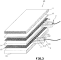
- Said panel also comprises a sixth layer 16 made of electrically insulating material, a second layer 12 made of electrically insulating material, a third layer 13 made of electrically conductive material, a fourth layer 14 made of electrically insulating material and a fifth layer 15 made of electrically conductive material.
- the electrically insulating material used to make the layers 12, 14 and 16 is a material which does not deform into a cone when it is stitched, unlike a sheet of cardboard for example.
- Said material can be a polyurethane or polystyrene foam.
- the material can also be of the wool type, for example glass wool or compressed rock wool.
- the material can also be fibrous, such as wood, especially balsa, or be a foam made from wood.
- Said material can also be a textile.
- the material is a so-called soft material whose density is less than 300 Kg / m3.
- the use of such a material makes it possible to easily insert, for example by hand, each power connector in the edge of the layers 12 and 14 or in the edge of the layers 14 and 16 of the panel.
- such a choice of materials makes it possible to insert each connector laterally in the panel in the manner of a thumbtack, without having to provide for a specific clearance within the panel and without risking damaging the connectors.
- the two electrically conductive layers 13, 15 are capable of forming two positive and negative (or phase and neutral) power supply tracks of a device electrical which includes two electrical contacts for its power supply.
- the two electrical contacts can be carried by the same pin 30 ( figure 2 ) or distributed over two pins 31, 32 ( figure 1 ). As detailed below, the or each pin is intended to be inserted into the panel 10 to bring one of the electrical contacts against the electrically conductive layer 13, and the other against the electrically conductive layer 15.
- the panel comprises at least one additional electrically conductive layer, which can be used to transmit a signal or be connected to earth.
- the tracks are intended to be connected by connectors 2 (detailed below) to an electrical supply, preferably a TBT or TBTS mains supply, for example a 12V supply.
- an electrical supply preferably a TBT or TBTS mains supply, for example a 12V supply.
- the SELV continuous supply can be carried out using a transformer connected to the SELV sector.
- the thickness of the electrically conductive layers 13 and 15 is less than the thickness of the other layers.
- the electrically conductive layers have in particular a thickness of less than 300 microns, and preferably have a thickness of the order of 100 to 200 microns.
- Said layers of the panel are bonded together.
- the layers 13 and 14, and 15 and 16 are bonded together by depositing lines of glue with a regular amount of glue along each line, to prevent an electrical contact area from a device pin electric crosses an area of excess adhesive and is thus electrically insulated from the electrically conductive layer with which said pin is intended to be in contact.
- a zone of excess adhesive thickness could form an insulation cone between the corresponding electrically conductive layer and the pin.
- Said lines of glue can be made in a straight and / or parallel manner, for example in a sinuous manner, without any point of inflection which would risk causing a larger local deposit of glue.
- Bonding is preferably carried out by a bonding process under hot pressure of the “hot melt” or hot-melt type, or cold bonding of the polyurethane adhesive type.
- the second layer 12 which isolates and separates the plate 11 from the electrically conductive layer 13 has a thickness less than that of each of the other layers 14, 16.
- the second layer 12 of electrically insulating material is of thickness at least equal to the diameter of the or each pin 30; 31, 32 of the electrical device 3 stitched into the panel to allow the cardboard sheet 112 to be maintained, which is deformed into a cone by the pin which passes through it, spaced from the electrically conductive layer 13.
- each of the electrically conductive layers 13, 15 comprises two metal sheets, preferably of aluminum, and a sheet of elastic material trapped between said metal sheets.
- each of the layers 13, 15 forms an elastic complex resembling the upper aluminum sheet against the pin which the cross member and thus promotes electrical contact between the corresponding contact carried by the pin and said electrically conductive layer.
- an electrical device preferably a lighting device 3, for example LED, is stitched on said sandwich panel 10.
- the electrical device comprises a pin 30 or two connection pins 31, 32 intended to be stitched into the panel 10.
- said pin carries two contacts 303, 305 at different heights being isolated from one another.
- the contacts 303, 305 are coaxial.
- the two contacts 303, 305 are intended to come respectively against the layers 13, 15 without touching the other layer 15, 13.
- the first pin 31 comprises a conductive portion 315 capable of coming into contact with the conductive layer 15 without being in electrical contact with the layer 13.
- the second pin 32 is capable of coming into contact contact with the conductive layer 13 without coming into electrical contact with the conductive layer 15.
- the absence of electrical contact between a pin and a given conductive layer can be achieved by designing the length of the pin so that in the pitted state, it crosses the other conductive layer but without reaching said given conductive layer (see the pin 32 of the figure 1 ) or so that the part of the pin which passes through said given conductive layer is electrically insulated (the part 313 of the pin 31 at the figure 1 is isolated from runway 13).
- the part of a pin intended to be insulated is provided with a coating which can be formed by a paint or insulating sheath, for example of rigid material.
- the sandwich panel 10 is further equipped with two connectors 2.
- One of the connectors 2 is able to connect one of the layers 13, 15 to one terminal of an electrical supply, and the other of the connectors is able to connect the other of the layers 13, 15 to the other terminal of the power supply.
- Each connector 2 has a U-shape.
- the free end of each branch 21, 22 is pointed and each branch 21, 22 of the U is split longitudinally from its free end to the connection zone between said branch 21, 22 and the bottom 20 of the U.
- Each layer 12, 14 and 16 has a sufficient thickness so that the branch of a connector can enter the thickness of said layer.
- Each connector can be equipped with a domino element to connect an electric wire at the level of the part forming the bottom of the U of the connector.
- the other end of the wire is connected to the power supply.
- said electrical wire can be soldered or crimped directly to the connector.
- Each branch 21, 22 of connector 2 is stitched on a edge of the sandwich panel 10 so that the branch portions which extend on either side of the slot 210, 220 of said branch are inserted respectively in the fourth and sixth layers 14, 16, or respectively in the second 12 and fourth 14 layers, which sandwich the third or fifth layer 13, 15 electrically conductive that the operator wishes to connect by said connector to the power supply.
- Each electrically conductive layer 13, 15 is taken in the slots 210, 220 of the corresponding connector 2 and in electrical contact with the corresponding slot edges.
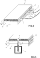
- the branches 21, 22 and the bottom 20 of the U of each connector are flat to allow it to be pushed in until the edge is pressed as illustrated in the figure 4 , and thus limit the size of the panel.
- said sandwich panel 10 can be fixed to a support 9, for example a metal rail or a wooden support such as a joist, using self-drilling screws 4.
- said screw 4 has a screw head and a metal body 40 which comprises a threaded end portion 42, and between said head and the threaded end portion, a smooth portion 41.
- the metal body 40 is preferably made of steel having undergone a heat treatment to make it self-drilling.
- Said smooth portion 41 has an electrically insulating coating, for example made of teflon or epoxy, preferably of a color different from that of the screw body 4 thus coated.
- Said coating is preferably in the form of a baked paint to prevent it from flaking. The color can be chosen white so as to allow visualization of a possible scratch which could degrade the electrical insulation of the smooth portion.
- the screw 4 has a diameter less than the thickness of the fourth layer 14, which makes it possible to prevent the fifth layer 15 from coming into contact by cone deformation with the third layer 13 during screwing.
- Said smooth portion 41 isolated from the screw 4 is of suitable length so as to pass through the third and fifth layers 13, 15 electrically conductive, while leaving part of the thread of the screw engaged in the sixth layer 16 to hold the sandwich panel 10 in abutment against the support 9 in which the screw 4 is taken.
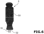
- the punching tool 5 comprises a gripping body 50 intended to be gripped by the hand of an operator, and one or two punches 51, 52 pointed at their free end and of elongated shape.
- the length of each punch is adapted to pass through the thickness of the plasterboard, in particular the rigid material caught between the sheets of cardboard.
- the gripping body 50 is elongated and of generally cylindrical shape.
- said punches are of the same length and extending parallel to one another from the face of the gripping body intended to be directed towards the panel.
- the axis of the grip body is parallel to the axis of each punch.
- the diameter of the punches 51, 52 is greater than or equal to the diameter of the pin or pins of the electrical device.
- the punching tool can thus be used to pre-drill the panel from the plate and subsequently insert the pin or pins of the electrical device into the panel, which is particularly advantageous when the two pins are not of the same length. Indeed, a stitching without pre-drilling with such an electrical device would risk bending the pins.
Landscapes
- Engineering & Computer Science (AREA)
- Architecture (AREA)
- Structural Engineering (AREA)
- Civil Engineering (AREA)
- Life Sciences & Earth Sciences (AREA)
- Wood Science & Technology (AREA)
- General Engineering & Computer Science (AREA)
- Coupling Device And Connection With Printed Circuit (AREA)
- Laminated Bodies (AREA)
- Installation Of Indoor Wiring (AREA)
- Mechanical Engineering (AREA)
Description
La présente invention concerne de manière générale les panneaux sandwich électriquement conducteurs auxquels sont destinés à être connectés électriquement des dispositifs électriques.The present invention relates generally to electrically conductive sandwich panels to which electrical devices are intended to be electrically connected.
On connaît de l'état de la technique des panneaux sandwich électriquement conducteur qui comprennent une première couche de mousse polyuréthane, une deuxième couche métallique, une troisième couche de mousse polyuréthane, une quatrième couche métallique et une cinquième couche de mousse polyuréthane. Lesdites couches métalliques forment des pistes d'alimentation électrique dans lesquelles peuvent être piquées des broches de dispositif d'éclairage à LED pour permettre d'alimenter lesdits dispositifs d'éclairage à LED.It is known from the state of the art electrically conductive sandwich panels which comprise a first layer of polyurethane foam, a second metal layer, a third layer of polyurethane foam, a fourth metal layer and a fifth layer of polyurethane foam. Said metal layers form electrical supply tracks into which LED lighting device pins can be stitched in order to power said LED lighting devices.
Ledit panneau peut être fixé sur un support au mur ou au plafond. La première couche en mousse polyuréthane, qui est orientée du côté intérieur de la pièce, est destinée à être habillée. Cependant, la demanderesse a constaté que ces panneaux sont fragiles et que les artisans ne savent généralement pas comment travailler ladite première couche pour l'habiller. En outre, la protection anti-feu qu'offre un tel panneau est faible.Said panel can be fixed on a support on the wall or on the ceiling. The first layer of polyurethane foam, which is oriented on the inside of the room, is intended to be dressed. However, the Applicant has found that these panels are fragile and that artisans generally do not know how to work said first layer to dress it. In addition, the fire protection offered by such a panel is weak.
La demanderesse a ainsi tenté dans un premier temps de remplacer la première couche en mousse de polyuréthane du panneau par une plaque de plâtre. Cependant, après avoir piqué les broches de dispositifs à LED à travers le panneau, la demanderesse a constaté que les dispositifs à LED ne fonctionnaient pas alors que les couches métalliques du panneau étaient bien alimentées.The Applicant thus first tried to replace the first layer of polyurethane foam in the panel with a plasterboard. However, after having stitched the pins of LED devices through the panel, the Applicant has found that the LED devices do not work while the metal layers of the panel are well supplied.
Le document
Le document
La présente invention a pour but de proposer un nouveau panneau permettant de palier à tout ou partie des problèmes exposés ci-dessus.The present invention aims to provide a new panel for overcoming all or part of the problems described above.
En particulier, un but de l'invention est de fournir un panneau résistant, dont la face d'exposition est facile à travailler, offrant une meilleure protection anti-feu et pour lequel le risque de dysfonctionnement des dispositifs électriques piqués dans le panneau est réduit.In particular, an object of the invention is to provide a resistant panel, the exposure face of which is easy to work, offering better fire protection and for which the risk of malfunction of the electrical devices stitched into the panel is reduced. .
A cet effet, l'invention a pour objet un panneau sandwich électriquement conducteur, caractérisé en ce que ledit panneau sandwich comprend dans l'ordre suivant :
- une première couche formée d'une plaque qui comprend deux feuilles de carton emprisonnant un matériau électriquement isolant, tel que du plâtre ;
- une deuxième couche en matériau électriquement isolant ;
- une troisième couche en matériau électriquement conducteur ;
- une quatrième couche en matériau électriquement isolant ;
- une cinquième couche en matériau électriquement conducteur ;
- une sixième couche en matériau électriquement isolant.
- a first layer formed of a plate which comprises two sheets of cardboard trapping an electrically insulating material, such as plaster;
- a second layer of electrically insulating material;
- a third layer of electrically conductive material;
- a fourth layer of electrically insulating material;
- a fifth layer of electrically conductive material;
- a sixth layer of electrically insulating material.
Lors du piquage d'une broche de dispositif électrique dans le panneau, la présence de la deuxième couche en matériau électriquement isolant entre la plaque et la piste d'alimentation formée par la troisième couche en matériau électriquement conducteur, permet à la deuxième feuille de carton de la plaque, de se déformer en cône contre cette deuxième couche, tandis que la deuxième couche laisse passer la broche sans venir s'interposer entre la broche et la piste d'alimentation au cours du piquage de la broche.When stitching an electrical device pin into the panel, the presence of the second layer of electrically insulating material between the plate and the feed track formed by the third layer of electrically conductive material, allows the second sheet of cardboard of the plate to deform into a cone against this second layer, while the second layer lets the pin pass without coming s '' Interpose between the spindle and the feed track during the spindle tapping.
Au contraire, dans la solution tentée par la demanderesse où le panneau était formé d'une plaque appliquée directement contre une piste d'alimentation formée par une couche métallique, le piquage de la broche dans le panneau provoquait la déformation en cône de la deuxième feuille de carton qui venait s'interposer entre la piste d'alimentation et la broche. Ainsi, la broche n'était plus suffisamment en contact électrique avec la piste d'alimentation car au moins partiellement isolée de la piste par la feuille de carton déformée. Il est fait remarquer que, si dans la solution tentée par la demanderesse décrite ci-avant, ladite plaque était une plaque de plâtre, le même problème de contact électrique se pose avec n'importe quelle autre plaque qui comprend deux feuilles de carton emprisonnant un matériau électriquement isolant, lorsque cette plaque est appliquée directement contre une piste d'alimentation formée par une couche métallique.On the contrary, in the solution attempted by the applicant where the panel was formed from a plate applied directly against a supply track formed by a metallic layer, the stitching of the pin in the panel caused the cone of the second sheet to be deformed of cardboard which came between the feed track and the spindle. Thus, the spindle was no longer sufficiently in electrical contact with the supply track because at least partially isolated from the track by the deformed cardboard sheet. It is pointed out that, if in the solution attempted by the applicant described above, said plate was a plasterboard, the same problem of electrical contact arises with any other plate which comprises two sheets of cardboard trapping a electrically insulating material, when this plate is applied directly against a supply track formed by a metallic layer.
La présence de la deuxième couche en matériau électriquement isolant, distincte d'une feuille de carton, permet de maintenir écartée la deuxième feuille de carton, même à l'état déformé en cône, par rapport à la piste d'alimentation formée par la troisième couche en matériau électriquement conducteur.The presence of the second layer of electrically insulating material, distinct from a sheet of cardboard, makes it possible to keep apart the second sheet of cardboard, even in the deformed cone state, relative to the supply track formed by the third layer of electrically conductive material.
Selon une caractéristique avantageuse de l'invention, les deuxième et troisième couches, ainsi que les quatrième et cinquième couches, sont collées entre elles par dépôt de lignes de colle avec une quantité régulière de colle le long de chaque ligne.According to an advantageous characteristic of the invention, the second and third layers, as well as the fourth and fifth layers, are bonded together by depositing lines of glue with a regular amount of glue along each line.
En particulier, la colle est déposée sous forme de cordons dont le diamètre est inférieur au diamètre de la ou chaque broche du dispositif piqué dans le panneau.In particular, the adhesive is deposited in the form of beads, the diameter of which is less than the diameter of the or each pin of the device stitched into the panel.
Selon une caractéristique avantageuse de l'invention, la deuxième couche présente une épaisseur inférieure à celle de chacune des quatrième et sixième couches.According to an advantageous characteristic of the invention, the second layer has a thickness less than that of each of the fourth and sixth layers.
Selon une caractéristique avantageuse de l'invention, au moins l'une, de préférence chacune, des couches électriquement conductrices comprend deux feuilles métalliques, de préférence en aluminium, et une feuille en matériau élastique emprisonnée entre lesdites feuilles métalliques.According to an advantageous characteristic of the invention, at least one, preferably each, of the electrically conductive layers comprises two metal sheets, preferably aluminum, and a sheet of elastic material trapped between said metal sheets.
Selon une caractéristique avantageuse de l'invention, ledit panneau sandwich est en outre équipé d'au moins un dispositif électrique, de préférence un dispositif d'éclairage, par exemple à LED, qui comprend une ou deux broches de connexion destinées à être piquées dans le panneau et portant deux contacts électriques, les deux contacts électriques étant répartis sur la ou chacune desdites broches de manière à ce que, à l'état piqué de la ou des broches dans le panneau, l'un des contacts électriques touche l'une des couches électriquement conductrice, sans toucher l'autre couche qui est touchée par l'autre contact électrique.According to an advantageous characteristic of the invention, said sandwich panel is also equipped with at least one electrical device, preferably a lighting device, for example LED, which comprises one or two connection pins intended to be poked in the panel and carrying two electrical contacts, the two electrical contacts being distributed over the or each of said pins so that, in the stitched state of the pin or pins in the panel, one of the electrical contacts touches one electrically conductive layers, without touching the other layer which is touched by the other electrical contact.
Selon un aspect particulier, la deuxième couche en matériau électriquement isolant est d'épaisseur au moins égale au diamètre de la ou de chaque broche du dispositif électrique piquée dans le panneau.According to a particular aspect, the second layer of electrically insulating material is of thickness at least equal to the diameter of the or each pin of the electrical device stitched into the panel.
L'invention concerne aussi un dispositif électrique, de préférence un dispositif d'éclairage, par exemple à LED, qui comprend une ou deux broches de connexion destinées à être piquées dans un panneau sandwich électriquement conducteur et portant deux contacts électriques, les deux contacts électriques étant répartis sur la ou chacune desdites broches de manière à ce que, à l'état piqué de la ou des broches dans le panneau, l'un des contacts électriques touche l'une des couches électriquement conductrice, sans toucher l'autre couche qui est touchée par l'autre contact électrique.The invention also relates to an electrical device, preferably a lighting device, for example an LED, which comprises one or two connection pins intended to be inserted into an electrically conductive sandwich panel and carrying two electrical contacts, the two electrical contacts. being distributed over the or each of said pins so that, in the stitched state of the pin or pins in the panel, one of the electrical contacts touches one of the electrically conductive layers, without touching the other layer which is affected by the other electrical contact.
Selon une caractéristique avantageuse de l'invention, ledit panneau sandwich est en outre équipé de deux connecteurs, l'un des connecteurs étant apte à connecter l'une des couches électriquement conductrices à une borne d'une alimentation électrique, et l'autre des connecteurs étant apte à connecter l'autre des couches électriquement conductrices à l'autre borne de l'alimentation électrique. Chaque connecteur présente une forme en U, l'extrémité libre de chaque branche étant pointue et chaque branche du U étant fendue longitudinalement depuis son extrémité libre jusqu'à la zone de liaison entre ladite branche et le fond du U.According to an advantageous characteristic of the invention, said sandwich panel is also equipped with two connectors, one of the connectors being able to connect one of the electrically conductive layers to a terminal of an electrical supply, and the other of the connectors being able to connect the other of the electrically conductive layers to the other terminal of the power supply. Each connector has a U shape, the free end of each branch being pointed and each branch of the U being split longitudinally from its free end to the connection zone between said branch and the bottom of the U.
Selon une caractéristique avantageuse de l'invention, chaque branche de connecteur est piquée sur une tranche du panneau sandwich de sorte que les portions de branche qui s'étendent de part et d'autre de la fente de ladite branche sont enfoncées respectivement dans les quatrième et sixième couches, ou respectivement dans les deuxième et quatrième couches, qui prennent en sandwich la troisième, ou respectivement cinquième, couche électriquement conductrice, ladite troisième, ou respectivement cinquième couche électriquement conductrice étant prise dans la fente et en contact électrique avec les bords de fente correspondant.According to an advantageous characteristic of the invention, each connector branch is pricked on a slice of the sandwich panel so that the branch portions which extend on either side of the slot in said branch are inserted respectively in the fourth and sixth layers, or respectively in the second and fourth layers, which sandwich the third, or respectively fifth, electrically conductive layer, said third, or respectively fifth electrically conductive layer being taken in the slot and in electrical contact with the edges of corresponding slot.
Selon une caractéristique avantageuse de l'invention, le matériau des deuxième, quatrième et sixième couches est de densité inférieure à 300 Kg/m3.According to an advantageous characteristic of the invention, the material of the second, fourth and sixth layers has a density of less than 300 Kg / m3.
L'invention concerne aussi un connecteur apte à connecter l'une des couches électriquement conductrices d'un panneau sandwich électriquement conducteur à une borne d'une alimentation électrique, le connecteur présentant une forme en U, l'extrémité libre de chaque branche étant pointue et chaque branche du U étant fendue longitudinalement depuis son extrémité libre jusqu'à la zone de liaison entre ladite branche et le fond du U.The invention also relates to a connector capable of connecting one of the electrically conductive layers of an electrically conductive sandwich panel to a terminal of an electrical supply, the connector having a U-shape, the free end of each branch being pointed. and each branch of the U being split longitudinally from its free end to the connection zone between said branch and the bottom of the U.
Selon une caractéristique avantageuse de l'invention, les branches et le fond du U formant chaque connecteur sont plats.According to an advantageous characteristic of the invention, the branches and the bottom of the U forming each connector are flat.
Selon une caractéristique avantageuse de l'invention, ledit panneau sandwich est en outre équipé de moyens de fixation dudit panneau sandwich sur un support, lesdits moyens de fixation comprenant une vis auto-foreuse qui présente une tête de vis et un corps métallique comprenant une portion d'extrémité filetée, et entre ladite tête et la portion d'extrémité filetée, une portion lisse, ladite portion lisse présentant un revêtement électriquement isolant, par exemple en téflon ou époxy, de préférence de couleur différente de celle du corps de vis ainsi revêtu.According to an advantageous characteristic of the invention, said sandwich panel is further equipped with means for fixing said sandwich panel to a support, said fixing means comprising a self-drilling screw which has a screw head and a metal body comprising a portion of threaded end, and between said head and the threaded end portion, a smooth portion, said smooth portion having an electrically insulating coating, for example of teflon or epoxy, preferably of a color different from that of the body of the screw thus coated .
L'invention concerne aussi une vis auto-foreuse pour la fixation d'un panneau sandwich électriquement conducteur, ladite vis présentant une tête de vis et un corps métallique comprenant une portion d'extrémité filetée, et entre ladite tête et la portion d'extrémité filetée, une portion lisse, ladite portion lisse présentant un revêtement électriquement isolant, par exemple en téflon ou époxy, de préférence de couleur différente de celle du corps de vis ainsi revêtu.The invention also relates to a self-drilling screw for fixing an electrically conductive sandwich panel, said screw having a screw head and a metal body comprising a threaded end portion, and between said head and the end portion threaded, a smooth portion, said smooth portion having an electrically insulating coating, for example made of teflon or epoxy, preferably of a different color from that of the screw body thus coated.
Selon une caractéristique avantageuse de l'invention, la vis présente un diamètre inférieur à l'épaisseur de la quatrième couche, c'est-à-dire de la couche interposée entre les deux pistes d'alimentation électrique formées par les troisième et cinquième couches.According to an advantageous characteristic of the invention, the screw has a diameter less than the thickness of the fourth layer, that is to say of the layer interposed between the two electrical supply tracks formed by the third and fifth layers .
Selon une caractéristique avantageuse de l'invention, ladite portion lisse est de longueur adaptée de manière à traverser les couches électriquement conductrices, tout en laissant une partie du filetage de la vis en prise dans la sixième couche pour maintenir le panneau sandwich en appui contre le support dans lequel est pris la vis.According to an advantageous characteristic of the invention, said smooth portion is of a length adapted so as to pass through the electrically conductive layers, while leaving part of the thread of the screw engaged in the sixth layer to hold the sandwich panel in abutment against the support in which the screw is taken.
L'invention concerne aussi un ensemble comprenant un panneau sandwich , au moins un dispositif électrique, qui comprend une ou deux broches de connexion destinée(s) à être piquée(s) dans le panneau sandwich, et un outil de poinçonnage comprenant un corps de saisie destiné à être saisi par la main d'un opérateur, et un ou deux poinçons de même longueur pointus à leur extrémité libre et de forme allongée.The invention also relates to an assembly comprising a sandwich panel, at least one electrical device, which comprises one or two connection pins intended to be inserted into the sandwich panel, and a punching tool comprising a body of gripping intended to be gripped by the hand of an operator, and one or two punches of the same length, pointed at their free end and of elongated shape.
Selon une caractéristique avantageuse de l'invention, le diamètre des poinçons est supérieur ou égal au diamètre de la ou des broches du dispositif électrique.According to an advantageous characteristic of the invention, the diameter of the punches is greater than or equal to the diameter of the pin or pins of the electrical device.
D'autres caractéristiques et avantages de l'invention ressortiront encore de la description qui suit, laquelle est purement illustrative et non limitative et doit être lue en regard des dessins annexés, sur lesquels :
- la
figure 1 est une vue en coupe d'un panneau sandwich et de deux broches de longueurs différentes d'un dispositif électrique piqué dans ledit panneau, conformément à un mode de réalisation de l'invention ; - la
figure 2 est une vue similaire à celle de lafigure 1 pour un mode de réalisation conforme à l'invention selon lequel le dispositif électrique comprend une seule broche ; - la
figure 3 est une vue éclatée en perspective d'un panneau sandwich et de deux connecteurs en U faisant apparaitre les fentes des branches du U conformément à un mode de réalisation de l'invention ; - la
figure 4 est une vue de lafigure 3 à l'état assemblé du panneau sandwich et à l'état inséré d'un des connecteurs sur une tranche du panneau, à cheval des couches électriquement conductrices correspondantes ; - la
figure 5 est une vue en perspective d'un panneau sandwich et d'une vis en prise dans un rail, conformément à un mode de réalisation de l'invention ; - la
figure 6 est une vue de face d'un outil de poinçonnage, conformément à un mode de réalisation de l'invention.
- the
figure 1 is a sectional view of a sandwich panel and two pins of different lengths of an electrical device stitched into said panel, in accordance with an embodiment of the invention; - the
figure 2 is a view similar to that of thefigure 1 for an embodiment according to the invention according to which the electrical device comprises a single pin; - the
figure 3 is an exploded perspective view of a sandwich panel and two U-shaped connectors showing the slots of the branches of the U in accordance with one embodiment of the invention; - the
figure 4 is a view of thefigure 3 in the assembled state of the sandwich panel and in the inserted state of one of the connectors on a side of the panel, straddling the corresponding electrically conductive layers; - the
figure 5 is a perspective view of a sandwich panel and a screw engaged in a rail, in accordance with an embodiment of the invention; - the
figure 6 is a front view of a punching tool, in accordance with an embodiment of the invention.
En référence aux figures et comme rappelé ci-dessus, l'invention concerne un panneau sandwich 10 électriquement conducteur auquel sont destinés à être connectés électriquement des dispositifs électriques. On entend par dispositif électrique tout dispositif ou appareil destinés à être alimentés électriquement tels qu'un dispositif d'éclairage, une prise de courant ou un capteur.With reference to the figures and as recalled above, the invention relates to an electrically
Le panneau sandwich 10 comprend une première couche 11 formée d'une plaque qui comprend deux feuilles 111, 112 de carton emprisonnant un matériau électriquement isolant, tel que du plâtre.The
En variante, le matériau de ladite plaque peut être du ciment ou un autre matériau. Ledit panneau comprend aussi une sixième couche 16 en matériau électriquement isolant, une deuxième couche 12 en matériau électriquement isolant, une troisième couche 13 en matériau électriquement conducteur, une quatrième couche 14 en matériau électriquement isolant et une cinquième couche 15 en matériau électriquement conducteur.As a variant, the material of said plate can be cement or another material. Said panel also comprises a
D'autres couches peuvent être ajoutées et/ou être interposées entre lesdites couches.Other layers can be added and / or be interposed between said layers.
Le matériau électriquement isolant utilisé pour réaliser les couches 12, 14 et 16 est un matériau qui ne se déforme pas en cône lorsqu'il est piqué, à la différence d'une feuille de carton par exemple. Ledit matériau peut être une mousse de polyuréthane ou polystyrène. Le matériau peut aussi être du type laine, par exemple de la laine de verre ou de roche compressée. Le matériau peut aussi être fibreux, tel que du bois, notamment du balsa, ou être une mousse faite à partir de bois. Ledit matériau peut aussi être un textile.The electrically insulating material used to make the
Préférentiellement, le matériau est un matériau dit tendre dont la densité est inférieure à 300 Kg/m3. L'utilisation d'un tel matériau permet d'enfoncer aisément, par exemple à la main, chaque connecteur d'alimentation dans la tranche des couches 12 et 14 ou dans la tranche des couches 14 et 16 du panneau. Autrement dit, un tel choix de matériaux permet d'insérer latéralement chaque connecteur dans le panneau à la manière d'une punaise, sans avoir à prévoir un dégagement spécifique au sein du panneau et sans risquer de détériorer les connecteurs.
Les deux couches électriquement conductrices 13, 15 sont aptes à former deux pistes d'alimentation positive et négative (ou phase et neutre) d'un dispositif électrique qui comprend deux contacts électriques pour son alimentation. Les deux contacts électriques peuvent être portés par une même broche 30 (
The two electrically
On peut aussi prévoir que le panneau comporte au moins une couche électriquement conductrice supplémentaire, qui peut être utilisée pour transmettre un signal ou être raccordée à la terre.It can also be provided that the panel comprises at least one additional electrically conductive layer, which can be used to transmit a signal or be connected to earth.
Les pistes sont destinées à être raccordées par des connecteurs 2 (détaillés ci-après) à une alimentation électrique, de préférence une alimentation secteur TBT ou TBTS, par exemple une alimentation de 12V. L'alimentation continue TBTS peut être réalisée à l'aide d'un transformateur raccordé au secteur TBT.The tracks are intended to be connected by connectors 2 (detailed below) to an electrical supply, preferably a TBT or TBTS mains supply, for example a 12V supply. The SELV continuous supply can be carried out using a transformer connected to the SELV sector.
L'épaisseur des couches électriquement conductrices 13 et 15 est inférieure à l'épaisseur des autres couches. Les couches électriquement conductrices présentent en particulier une épaisseur inférieure à 300 microns, et de préférence présentent une épaisseur de l'ordre de 100 à 200 microns.The thickness of the electrically
Lesdites couches du panneau sont collées entre elles. En particulier, les couches 13 et 14, et 15 et 16 sont collées entre elles par dépôt de lignes de colle avec une quantité régulière de colle le long de chaque ligne, pour éviter qu'une zone de contact électrique d'une broche de dispositif électrique traverse une zone de surépaisseur de colle et soit ainsi isolée électriquement de la couche électriquement conductrice avec laquelle ladite broche est destinée à être en contact. En effet une zone de surépaisseur de colle pourrait former un cône d'isolation entre la couche électriquement conductrice correspondante et la broche.Said layers of the panel are bonded together. In particular, the
Lesdites lignes de colle peuvent être réalisées de manière droite et/ou parallèle, par exemple de façon sinueuse, sans point d'inflexion qui risquerait d'entrainer un dépôt local plus important de colle.Said lines of glue can be made in a straight and / or parallel manner, for example in a sinuous manner, without any point of inflection which would risk causing a larger local deposit of glue.
Le collage est réalisé de préférence par un procédé de collage sous pression à chaud de type « hot melt» ou thermofusible, ou à froid de type colle polyuréthane.Bonding is preferably carried out by a bonding process under hot pressure of the “hot melt” or hot-melt type, or cold bonding of the polyurethane adhesive type.
Selon un mode de réalisation, la deuxième couche 12 qui isole et écarte la plaque 11 de la couche électriquement conductrice 13 présente une épaisseur inférieure à celle de chacune des autres couches 14, 16.According to one embodiment, the
Selon un aspect particulier, la deuxième couche 12 en matériau électriquement isolant est d'épaisseur au moins égale au diamètre de la ou de chaque broche 30 ; 31, 32 du dispositif électrique 3 piquée dans le panneau pour permettre de maintenir la feuille de carton 112, qui est déformée en cône par la broche qui la traverse, écartée de la couche électriquement conductrice 13.According to a particular aspect, the
Avantageusement, chacune des couches 13, 15 électriquement conductrices comprend deux feuilles métalliques, de préférence en aluminium, et une feuille en matériau élastique emprisonnée entre lesdites feuilles métalliques. Ainsi, lorsqu'un dispositif électrique muni d'une ou de deux broches portant les contacts électriques, est piqué dans le panneau depuis la plaque, chacune des couches 13, 15 forme un complexe élastique rappelant la feuille d'aluminium supérieure contre la broche qui la traverse et ainsi favorise le contact électrique entre le contact correspondant porté par la broche et ladite couche électriquement conductrice.Advantageously, each of the electrically
Selon un mode de réalisation, un dispositif électrique, de préférence un dispositif d'éclairage 3 par exemple à LED, est piqué sur ledit panneau sandwich 10. A cet effet, le dispositif électrique comprend une broche 30 ou deux broches 31, 32 de connexion destinées à être piquées dans le panneau 10. Dans le cas d'un dispositif à une broche, ladite broche porte deux contacts 303, 305 à des hauteurs différentes en étant isolés l'un de l'autre. Dans le cas illustré à la
Dans l'exemple illustré à la
L'absence de contact électrique entre une broche et une couche conductrice donnée peut être réalisée en concevant la longueur de la broche de sorte que à l'état piqué, elle traverse l'autre couche conductrice mais sans atteindre ladite couche conductrice donnée (voir la broche 32 de la
La partie d'une broche destinée à être isolée est munie d'un revêtement qui peut être formé par une peinture ou gaine isolante par exemple en matériau rigide.The part of a pin intended to be insulated is provided with a coating which can be formed by a paint or insulating sheath, for example of rigid material.
Le panneau sandwich 10 est en outre équipé de deux connecteurs 2.The
L'un des connecteurs 2 est apte à connecter l'une des couches 13, 15 à une borne d'une alimentation électrique, et l'autre des connecteurs est apte à connecter l'autre des couches 13, 15 à l'autre borne de l'alimentation électrique.One of the
Chaque connecteur 2 présente une forme en U. L'extrémité libre de chaque branche 21, 22 est pointue et chaque branche 21, 22 du U est fendue longitudinalement depuis son extrémité libre jusqu'à la zone de liaison entre ladite branche 21, 22 et le fond 20 du U.Each
Chaque couche 12, 14 et 16 présente une épaisseur suffisante pour que la branche d'un connecteur puisse rentrer dans l'épaisseur de ladite couche.Each
Chaque connecteur peut être équipé d'un élément formant domino pour raccorder un fil électrique au niveau de la partie formant le fond du U du connecteur. L'autre extrémité du fil électrique est raccordée à l'alimentation électrique. En variante, ledit fil électrique peut être soudé ou serti directement au connecteur.Each connector can be equipped with a domino element to connect an electric wire at the level of the part forming the bottom of the U of the connector. The other end of the wire is connected to the power supply. Alternatively, said electrical wire can be soldered or crimped directly to the connector.
Chaque branche 21, 22 de connecteur 2 est piquée sur une tranche du panneau sandwich 10 de sorte que les portions de branche qui s'étendent de part et d'autre de la fente 210, 220 de ladite branche sont enfoncées respectivement dans les quatrième et sixième couches 14, 16, ou respectivement dans les deuxième 12 et quatrième 14 couches, qui prennent en sandwich la troisième ou cinquième couche 13, 15 électriquement conductrice que l'opérateur souhaite raccorder par ledit connecteur à l'alimentation électrique.Each
Chaque couche 13, 15 électriquement conductrice est prise dans les fentes 210, 220 du connecteur 2 correspondant et en contact électrique avec les bords de fente correspondant.Each electrically
Les branches 21, 22 et le fond 20 du U de chaque connecteur sont plats pour permettre de l'enfoncer jusqu'en appui de la tranche comme illustré à la
Comme illustré à la
Selon un mode de réalisation, ladite vis 4 présente une tête de vis et un corps 40 métallique qui comprend une portion d'extrémité 42 filetée, et entre ladite tête et la portion d'extrémité filetée, une portion lisse 41. Le corps 40 métallique est de préférence en acier ayant subi un traitement thermique pour le rendre autoforant.According to one embodiment, said
Ladite portion lisse 41 présente un revêtement électriquement isolant, par exemple en téflon ou en époxy, de préférence de couleur différente de celle du corps de vis 4 ainsi revêtu. Ledit revêtement se présente de préférence sous forme d'une peinture cuite pour éviter qu'elle ne s'écaille. La couleur peut être choisie blanche de manière à permettre de visualiser une éventuelle rayure qui pourrait dégrader l'isolation électrique de la portion lisse.Said
La vis 4 présente un diamètre inférieur à l'épaisseur de la quatrième couche 14, ce qui permet d'éviter que la cinquième couche 15 ne vienne en contact par déformation en cône avec la troisième couche 13 au cours du vissage.The
Ladite portion lisse 41 isolée de la vis 4 est de longueur adaptée de manière à traverser les troisième et cinquième couches 13, 15 électriquement conductrices, tout en laissant une partie du filetage de la vis en prise dans la sixième couche 16 pour maintenir le panneau sandwich 10 en appui contre le support 9 dans lequel est pris la vis 4.Said
Selon un mode de réalisation, il est prévu de faciliter le piquage, dans le panneau sandwich, d'un dispositif électrique à une ou deux broches de connexion, par exemple conforme à celui présenté en
L'outil de poinçonnage 5 comprend un corps 50 de saisie destiné à être saisi par la main d'un opérateur, et un ou deux poinçons 51, 52 pointus à leur extrémité libre et de forme allongée. La longueur de chaque poinçon est adaptée pour traverser l'épaisseur de la plaque de plâtre, en particulier le matériau rigide pris entre les feuilles de carton. Le corps 50 de saisie est allongé et de forme générale cylindrique.The
Selon un mode de réalisation et dans le cas d'un outil de poinçonnage 5 à deux poinçons 51, 52, lesdits poinçons sont de même longueur et s'étendant parallèlement l'un par rapport à l'autre depuis la face du corps de saisie destinée à être dirigée vers le panneau. L'axe du corps de saisie est parallèle à l'axe de chaque poinçon.According to one embodiment and in the case of a
On peut prévoir que le diamètre des poinçons 51, 52 est supérieur ou égal au diamètre de la ou des broches du dispositif électrique.It can be provided that the diameter of the
L'outil de poinçonnage peut ainsi être utilisé pour pré-percer le panneau depuis la plaque et insérer par la suite la ou les broches du dispositif électrique dans le panneau, ce qui est particulièrement avantageux lorsque les deux broches ne sont pas de même longueur. En effet, un piquage sans pré-perçage avec un tel dispositif électrique risquerait de tordre les broches.The punching tool can thus be used to pre-drill the panel from the plate and subsequently insert the pin or pins of the electrical device into the panel, which is particularly advantageous when the two pins are not of the same length. Indeed, a stitching without pre-drilling with such an electrical device would risk bending the pins.
L'invention n'est pas limitée aux modes de réalisation illustrés dans les dessins. En conséquence, il doit être entendu que, lorsque les caractéristiques mentionnées dans les revendications annexées sont suivies par des signes de référence, ces signes sont inclus uniquement dans le but d'améliorer l'intelligibilité des revendications et ne sont nullement limitatifs de la portée des revendications.The invention is not limited to the embodiments illustrated in the drawings. Consequently, it should be understood that, when the features mentioned in the appended claims are followed by reference signs, these signs are included only for the purpose of improving the intelligibility of the claims and are in no way limitative of the scope of the claims.
De plus, le terme « comprenant » n'exclut pas d'autres éléments ou étapes. En outre, des caractéristiques ou étapes qui ont été décrites en référence à l'un des modes de réalisation exposés ci-dessus peuvent également être utilisées en combinaison avec d'autres caractéristiques ou étapes d'autres modes de réalisation exposés ci-dessus.In addition, the term "comprising" does not exclude other elements or steps. In addition, features or steps which have been described with reference to one of the embodiments set out above can also be used in combination with other features or steps of other embodiments set out above.
Claims (14)
- An electrically conductive sandwich panel (10), characterized in that said sandwich panel (10) comprises, in the following order:- a first layer (11) formed by a plate that comprises two sheets (111, 112) of cardboard capturing an electrically insulating material, such as plaster;- a second layer (12) made from electrically insulating material;- a third layer (13) made from electrically conductive material;- a fourth layer (14) made from electrically insulating material;- a fifth layer (15) made from electrically conductive material;- a sixth layer (16) made from electrically insulating material.
- The sandwich panel (10) according to claim 1, characterized in that the second and third layers (12, 13), as well as the fourth and fifth layers (14, 15), are glued to one another by depositing lines of glue with a regular quantity of glue along each line.
- The sandwich panel (10) according to one of the preceding claims, characterized in that at least one, preferably each, of the electrically conductive layers (13, 15) comprises two metallic sheets, preferably made from aluminum, and one sheet of resilient material captured between said metallic sheets.
- The sandwich panel (10) according to one of the preceding claims, characterized in that said sandwich panel (10) is further equipped with at least one electrical device, preferably a lighting device (3), for example by LED, that comprises one or two connection pins (31, 32) intended to be stuck in the panel (10) and bearing two electrical contacts, the two electrical contacts being distributed on the or each of said pins (31, 32) such that, in the state of the pin(s) stuck in the panel (10), one of the electrical contacts touches one of the electrically conductive layers (13, 15), without touching the other layer (15, 13) that is touched by the other electrical contact.
- The sandwich panel (10) according to claim 4, characterized in that the second layer (12) made from electrically insulating material has a thickness at least equal to the diameter of the or each pin (30; 31, 32) of the electrical device (3) stuck in the panel.
- The sandwich panel (10) according to one of the preceding claims, characterized in that said sandwich panel (10) is further equipped with two connectors (2), one of the connectors being suitable for connecting one of the electrically conductive layers (13, 15) to a terminal of an electrical power source, and the other of the connectors being able to connect the other of the electrically conductive layers (13, 15) to the other terminal of the electrical power source,
and in that each connector (2) is U-shaped, the free end of each branch (21, 22) being pointed and each branch (21, 22) of the U being longitudinally slotted (210, 220) from its free end to the connecting zone between said branch (21, 22) and the bottom (20) of the U. - The sandwich panel (10) according to claim 6, characterized in that each connector (2) branch (21, 22) is stuck on an edge of the sandwich panel (10) such that the branch portions that extend on either side of the slot of said branch are respectively pushed into the fourth and sixth layers (14, 16), or respectively into the second (12) and fourth (14) layers, which sandwich the electrically conductive third or fifth layer (13, 15), said electrically conductive third or fifth layer (13, 15) being engaged in the slot and electrically in contact with the corresponding slot edges.
- The sandwich panel (10) according to claim 7, characterized in that the material of the second (12), fourth (14) and sixth (16) layers has a density below 300 kg/m3.
- The sandwich panel (10) according to claim 8, characterized in that the branches (21, 22) and the bottom (20) of the U forming each connector (2) are flat.
- The sandwich panel (10) according to one of the preceding claims, characterized in that said sandwich panel (10) is further equipped with means for fastening said sandwich panel (10) on a support (9), said fastening means comprising a self-tapping screw (4) that has a screw head and a metallic body (40) comprising a threaded end portion (42), and between said head and the threaded end portion, a smooth portion (41), said smooth portion (41) having an electrically insulating coating, for example made from Teflon or epoxy, preferably with a color different from that of the screw body (4) thus coated.
- The sandwich panel (10) according to claim 10, characterized in that the screw (4) has a diameter smaller than the thickness of the fourth layer (14).
- The sandwich panel (10) according to claim 10 or 11, characterized in that said smooth portion (41) has a length suitable for passing through the electrically conductive layers (13, 15), while leaving part of the thread of the screw engaged in the sixth layer (16) to keep the sandwich panel (10) bearing against the support (9) in which the screw (4) is engaged.
- An assembly comprising:- a sandwich panel (10) according to one of the preceding claims,- at least one electrical device (3) that comprises one or two connection pins (31, 32) suitable for being stuck in the sandwich panel (10), and- a punching tool (5) comprising a grasping body (50) suitable for being grasped by the hand of an operator, and one or two punches (51, 52) of equal length, pointed at their free ends and of elongated shape.
- The assembly according to claim 13, characterized in that the diameter of the punches (51, 52) is greater than or equal to the diameter of the pin(s) (31, 32) of the electrical device (3).
Applications Claiming Priority (2)
| Application Number | Priority Date | Filing Date | Title |
|---|---|---|---|
| FR1554618A FR3036309B1 (en) | 2015-05-22 | 2015-05-22 | ELECTRICALLY CONDUCTIVE SANDWICH PANEL |
| PCT/FR2016/051199 WO2016189236A1 (en) | 2015-05-22 | 2016-05-20 | Electrically conducting sandwich panel |
Publications (2)
| Publication Number | Publication Date |
|---|---|
| EP3297828A1 EP3297828A1 (en) | 2018-03-28 |
| EP3297828B1 true EP3297828B1 (en) | 2020-03-18 |
Family
ID=53496869
Family Applications (1)
| Application Number | Title | Priority Date | Filing Date |
|---|---|---|---|
| EP16731218.0A Active EP3297828B1 (en) | 2015-05-22 | 2016-05-20 | Electrically conducting sandwich panel |
Country Status (4)
| Country | Link |
|---|---|
| US (1) | US10502405B2 (en) |
| EP (1) | EP3297828B1 (en) |
| FR (1) | FR3036309B1 (en) |
| WO (1) | WO2016189236A1 (en) |
Family Cites Families (5)
| Publication number | Priority date | Publication date | Assignee | Title |
|---|---|---|---|---|
| DE10300857A1 (en) * | 2003-01-10 | 2004-07-29 | Vossloh-Wustlich Opto Gmbh & Co.Kg | Panel-like clothing element, in particular for walls, ceilings or floors of buildings, and clothing made therefrom |
| DE202004011454U1 (en) * | 2004-07-21 | 2004-09-23 | Hutzenlaub, Jens | Electrical ceiling lighting has laminated panels into which modified LED elements are inserted |
| WO2007006147A1 (en) | 2005-07-14 | 2007-01-18 | Tir Systems Ltd. | Power board and plug-in lighting module |
| DE102012013831B4 (en) * | 2012-07-13 | 2019-08-22 | Lohmann Gmbh & Co. Kg | LED board |
| US9332632B2 (en) * | 2014-08-20 | 2016-05-03 | Stablcor Technology, Inc. | Graphene-based thermal management cores and systems and methods for constructing printed wiring boards |
-
2015
- 2015-05-22 FR FR1554618A patent/FR3036309B1/en not_active Expired - Fee Related
-
2016
- 2016-05-20 WO PCT/FR2016/051199 patent/WO2016189236A1/en not_active Ceased
- 2016-05-20 US US15/574,725 patent/US10502405B2/en active Active
- 2016-05-20 EP EP16731218.0A patent/EP3297828B1/en active Active
Non-Patent Citations (1)
| Title |
|---|
| None * |
Also Published As
| Publication number | Publication date |
|---|---|
| US10502405B2 (en) | 2019-12-10 |
| FR3036309A1 (en) | 2016-11-25 |
| WO2016189236A1 (en) | 2016-12-01 |
| US20180135844A1 (en) | 2018-05-17 |
| FR3036309B1 (en) | 2017-06-16 |
| EP3297828A1 (en) | 2018-03-28 |
Similar Documents
| Publication | Publication Date | Title |
|---|---|---|
| WO2012010662A3 (en) | Process for direct bonding two elements comprising copper portions and dielectric materials | |
| FR2953677A1 (en) | ULTRASOUND INTEGRATED CONDUCTIVE WIRE GLAZING | |
| EP3297828B1 (en) | Electrically conducting sandwich panel | |
| EP0262022A1 (en) | Pipe works for a centralized suction-cleaning plant, and method of realizing a pipe usable in such a pipe works | |
| EP3227966B1 (en) | Electrical connection element penetrating an electrical wire insulation sheath | |
| CA2993755A1 (en) | Expandable room comprising a partition electrically connectable to a wall or a ceiling | |
| EP2554893B1 (en) | LED lamp device and automated method for manufacturing said device | |
| EP3162980B1 (en) | Bracing device for lining a structure | |
| EP3286497B1 (en) | Illuminating planar mounting device | |
| FR2942083A1 (en) | Flexible elements i.e. electric cables/wires, fixing device for e.g. motor-controller unit of motor vehicle, has support comprising units to maintain ends of elements to be fixed to case, and holes to position support in relation to case | |
| EP0181362B1 (en) | Female elements for electric connector, and method for making them | |
| FR2792041A1 (en) | WOOD PANEL ASSEMBLY SYSTEM | |
| AU2003246641A1 (en) | Method for joining lacquered wires in an electrically conducting manner | |
| EP3349305B1 (en) | Improved electrical connection kit | |
| FR3054403A1 (en) | GLAZING WITH ELECTRICALLY CONDUCTIVE ELEMENT AND ELECTRICAL CONNECTION | |
| EP2439815A1 (en) | Electrical connection device, intended in particular for a cable raceway | |
| EP3099148B1 (en) | Printed circuit including a hinge | |
| EP0708493B1 (en) | Connection terminal with self-stripping connection device with screw drive | |
| FR3053168A1 (en) | CONNECTOR CONNECTION | |
| EP3336967A1 (en) | Electrical connection element | |
| FR3029675A1 (en) | LUMINOUS DISPLAY PANEL | |
| CN101311434A (en) | Jointing construction for stone | |
| EP3089171B1 (en) | Flat power supply line, associated supply network and manufacturing method | |
| WO2015086650A1 (en) | Device for holding a press against an object | |
| FR3028675A1 (en) | ARRANGEMENT FOR PREVENTING THE ROTATION OF AN ELECTRICAL TERMINAL AND METHOD OF MANUFACTURING THE SAME. |
Legal Events
| Date | Code | Title | Description |
|---|---|---|---|
| STAA | Information on the status of an ep patent application or granted ep patent |
Free format text: STATUS: THE INTERNATIONAL PUBLICATION HAS BEEN MADE |
|
| PUAI | Public reference made under article 153(3) epc to a published international application that has entered the european phase |
Free format text: ORIGINAL CODE: 0009012 |
|
| STAA | Information on the status of an ep patent application or granted ep patent |
Free format text: STATUS: REQUEST FOR EXAMINATION WAS MADE |
|
| 17P | Request for examination filed |
Effective date: 20171115 |
|
| AK | Designated contracting states |
Kind code of ref document: A1 Designated state(s): AL AT BE BG CH CY CZ DE DK EE ES FI FR GB GR HR HU IE IS IT LI LT LU LV MC MK MT NL NO PL PT RO RS SE SI SK SM TR |
|
| AX | Request for extension of the european patent |
Extension state: BA ME |
|
| DAV | Request for validation of the european patent (deleted) | ||
| DAX | Request for extension of the european patent (deleted) | ||
| STAA | Information on the status of an ep patent application or granted ep patent |
Free format text: STATUS: EXAMINATION IS IN PROGRESS |
|
| 17Q | First examination report despatched |
Effective date: 20181114 |
|
| GRAP | Despatch of communication of intention to grant a patent |
Free format text: ORIGINAL CODE: EPIDOSNIGR1 |
|
| STAA | Information on the status of an ep patent application or granted ep patent |
Free format text: STATUS: GRANT OF PATENT IS INTENDED |
|
| INTG | Intention to grant announced |
Effective date: 20191010 |
|
| GRAS | Grant fee paid |
Free format text: ORIGINAL CODE: EPIDOSNIGR3 |
|
| GRAA | (expected) grant |
Free format text: ORIGINAL CODE: 0009210 |
|
| STAA | Information on the status of an ep patent application or granted ep patent |
Free format text: STATUS: THE PATENT HAS BEEN GRANTED |
|
| AK | Designated contracting states |
Kind code of ref document: B1 Designated state(s): AL AT BE BG CH CY CZ DE DK EE ES FI FR GB GR HR HU IE IS IT LI LT LU LV MC MK MT NL NO PL PT RO RS SE SI SK SM TR |
|
| REG | Reference to a national code |
Ref country code: GB Ref legal event code: FG4D Free format text: NOT ENGLISH |
|
| REG | Reference to a national code |
Ref country code: DE Ref legal event code: R096 Ref document number: 602016032030 Country of ref document: DE |
|
| REG | Reference to a national code |
Ref country code: AT Ref legal event code: REF Ref document number: 1245461 Country of ref document: AT Kind code of ref document: T Effective date: 20200415 Ref country code: IE Ref legal event code: FG4D Free format text: LANGUAGE OF EP DOCUMENT: FRENCH |
|
| PG25 | Lapsed in a contracting state [announced via postgrant information from national office to epo] |
Ref country code: NO Free format text: LAPSE BECAUSE OF FAILURE TO SUBMIT A TRANSLATION OF THE DESCRIPTION OR TO PAY THE FEE WITHIN THE PRESCRIBED TIME-LIMIT Effective date: 20200618 Ref country code: FI Free format text: LAPSE BECAUSE OF FAILURE TO SUBMIT A TRANSLATION OF THE DESCRIPTION OR TO PAY THE FEE WITHIN THE PRESCRIBED TIME-LIMIT Effective date: 20200318 Ref country code: RS Free format text: LAPSE BECAUSE OF FAILURE TO SUBMIT A TRANSLATION OF THE DESCRIPTION OR TO PAY THE FEE WITHIN THE PRESCRIBED TIME-LIMIT Effective date: 20200318 |
|
| REG | Reference to a national code |
Ref country code: NL Ref legal event code: MP Effective date: 20200318 |
|
| PG25 | Lapsed in a contracting state [announced via postgrant information from national office to epo] |
Ref country code: BG Free format text: LAPSE BECAUSE OF FAILURE TO SUBMIT A TRANSLATION OF THE DESCRIPTION OR TO PAY THE FEE WITHIN THE PRESCRIBED TIME-LIMIT Effective date: 20200618 Ref country code: GR Free format text: LAPSE BECAUSE OF FAILURE TO SUBMIT A TRANSLATION OF THE DESCRIPTION OR TO PAY THE FEE WITHIN THE PRESCRIBED TIME-LIMIT Effective date: 20200619 Ref country code: LV Free format text: LAPSE BECAUSE OF FAILURE TO SUBMIT A TRANSLATION OF THE DESCRIPTION OR TO PAY THE FEE WITHIN THE PRESCRIBED TIME-LIMIT Effective date: 20200318 Ref country code: SE Free format text: LAPSE BECAUSE OF FAILURE TO SUBMIT A TRANSLATION OF THE DESCRIPTION OR TO PAY THE FEE WITHIN THE PRESCRIBED TIME-LIMIT Effective date: 20200318 Ref country code: HR Free format text: LAPSE BECAUSE OF FAILURE TO SUBMIT A TRANSLATION OF THE DESCRIPTION OR TO PAY THE FEE WITHIN THE PRESCRIBED TIME-LIMIT Effective date: 20200318 |
|
| REG | Reference to a national code |
Ref country code: LT Ref legal event code: MG4D |
|
| PG25 | Lapsed in a contracting state [announced via postgrant information from national office to epo] |
Ref country code: NL Free format text: LAPSE BECAUSE OF FAILURE TO SUBMIT A TRANSLATION OF THE DESCRIPTION OR TO PAY THE FEE WITHIN THE PRESCRIBED TIME-LIMIT Effective date: 20200318 |
|
| PG25 | Lapsed in a contracting state [announced via postgrant information from national office to epo] |
Ref country code: LT Free format text: LAPSE BECAUSE OF FAILURE TO SUBMIT A TRANSLATION OF THE DESCRIPTION OR TO PAY THE FEE WITHIN THE PRESCRIBED TIME-LIMIT Effective date: 20200318 Ref country code: RO Free format text: LAPSE BECAUSE OF FAILURE TO SUBMIT A TRANSLATION OF THE DESCRIPTION OR TO PAY THE FEE WITHIN THE PRESCRIBED TIME-LIMIT Effective date: 20200318 Ref country code: IS Free format text: LAPSE BECAUSE OF FAILURE TO SUBMIT A TRANSLATION OF THE DESCRIPTION OR TO PAY THE FEE WITHIN THE PRESCRIBED TIME-LIMIT Effective date: 20200718 Ref country code: SK Free format text: LAPSE BECAUSE OF FAILURE TO SUBMIT A TRANSLATION OF THE DESCRIPTION OR TO PAY THE FEE WITHIN THE PRESCRIBED TIME-LIMIT Effective date: 20200318 Ref country code: CZ Free format text: LAPSE BECAUSE OF FAILURE TO SUBMIT A TRANSLATION OF THE DESCRIPTION OR TO PAY THE FEE WITHIN THE PRESCRIBED TIME-LIMIT Effective date: 20200318 Ref country code: PT Free format text: LAPSE BECAUSE OF FAILURE TO SUBMIT A TRANSLATION OF THE DESCRIPTION OR TO PAY THE FEE WITHIN THE PRESCRIBED TIME-LIMIT Effective date: 20200812 Ref country code: EE Free format text: LAPSE BECAUSE OF FAILURE TO SUBMIT A TRANSLATION OF THE DESCRIPTION OR TO PAY THE FEE WITHIN THE PRESCRIBED TIME-LIMIT Effective date: 20200318 Ref country code: SM Free format text: LAPSE BECAUSE OF FAILURE TO SUBMIT A TRANSLATION OF THE DESCRIPTION OR TO PAY THE FEE WITHIN THE PRESCRIBED TIME-LIMIT Effective date: 20200318 |
|
| REG | Reference to a national code |
Ref country code: AT Ref legal event code: MK05 Ref document number: 1245461 Country of ref document: AT Kind code of ref document: T Effective date: 20200318 |
|
| REG | Reference to a national code |
Ref country code: DE Ref legal event code: R097 Ref document number: 602016032030 Country of ref document: DE |
|
| PLBE | No opposition filed within time limit |
Free format text: ORIGINAL CODE: 0009261 |
|
| STAA | Information on the status of an ep patent application or granted ep patent |
Free format text: STATUS: NO OPPOSITION FILED WITHIN TIME LIMIT |
|
| PG25 | Lapsed in a contracting state [announced via postgrant information from national office to epo] |
Ref country code: IT Free format text: LAPSE BECAUSE OF FAILURE TO SUBMIT A TRANSLATION OF THE DESCRIPTION OR TO PAY THE FEE WITHIN THE PRESCRIBED TIME-LIMIT Effective date: 20200318 Ref country code: MC Free format text: LAPSE BECAUSE OF FAILURE TO SUBMIT A TRANSLATION OF THE DESCRIPTION OR TO PAY THE FEE WITHIN THE PRESCRIBED TIME-LIMIT Effective date: 20200318 Ref country code: AT Free format text: LAPSE BECAUSE OF FAILURE TO SUBMIT A TRANSLATION OF THE DESCRIPTION OR TO PAY THE FEE WITHIN THE PRESCRIBED TIME-LIMIT Effective date: 20200318 Ref country code: DK Free format text: LAPSE BECAUSE OF FAILURE TO SUBMIT A TRANSLATION OF THE DESCRIPTION OR TO PAY THE FEE WITHIN THE PRESCRIBED TIME-LIMIT Effective date: 20200318 Ref country code: ES Free format text: LAPSE BECAUSE OF FAILURE TO SUBMIT A TRANSLATION OF THE DESCRIPTION OR TO PAY THE FEE WITHIN THE PRESCRIBED TIME-LIMIT Effective date: 20200318 |
|
| 26N | No opposition filed |
Effective date: 20201221 |
|
| PG25 | Lapsed in a contracting state [announced via postgrant information from national office to epo] |
Ref country code: PL Free format text: LAPSE BECAUSE OF FAILURE TO SUBMIT A TRANSLATION OF THE DESCRIPTION OR TO PAY THE FEE WITHIN THE PRESCRIBED TIME-LIMIT Effective date: 20200318 |
|
| PG25 | Lapsed in a contracting state [announced via postgrant information from national office to epo] |
Ref country code: LU Free format text: LAPSE BECAUSE OF NON-PAYMENT OF DUE FEES Effective date: 20200520 |
|
| PG25 | Lapsed in a contracting state [announced via postgrant information from national office to epo] |
Ref country code: IE Free format text: LAPSE BECAUSE OF NON-PAYMENT OF DUE FEES Effective date: 20200520 |
|
| PG25 | Lapsed in a contracting state [announced via postgrant information from national office to epo] |
Ref country code: SI Free format text: LAPSE BECAUSE OF FAILURE TO SUBMIT A TRANSLATION OF THE DESCRIPTION OR TO PAY THE FEE WITHIN THE PRESCRIBED TIME-LIMIT Effective date: 20200318 |
|
| PG25 | Lapsed in a contracting state [announced via postgrant information from national office to epo] |
Ref country code: TR Free format text: LAPSE BECAUSE OF FAILURE TO SUBMIT A TRANSLATION OF THE DESCRIPTION OR TO PAY THE FEE WITHIN THE PRESCRIBED TIME-LIMIT Effective date: 20200318 Ref country code: MT Free format text: LAPSE BECAUSE OF FAILURE TO SUBMIT A TRANSLATION OF THE DESCRIPTION OR TO PAY THE FEE WITHIN THE PRESCRIBED TIME-LIMIT Effective date: 20200318 Ref country code: CY Free format text: LAPSE BECAUSE OF FAILURE TO SUBMIT A TRANSLATION OF THE DESCRIPTION OR TO PAY THE FEE WITHIN THE PRESCRIBED TIME-LIMIT Effective date: 20200318 |
|
| PG25 | Lapsed in a contracting state [announced via postgrant information from national office to epo] |
Ref country code: MK Free format text: LAPSE BECAUSE OF FAILURE TO SUBMIT A TRANSLATION OF THE DESCRIPTION OR TO PAY THE FEE WITHIN THE PRESCRIBED TIME-LIMIT Effective date: 20200318 Ref country code: AL Free format text: LAPSE BECAUSE OF FAILURE TO SUBMIT A TRANSLATION OF THE DESCRIPTION OR TO PAY THE FEE WITHIN THE PRESCRIBED TIME-LIMIT Effective date: 20200318 |
|
| PGFP | Annual fee paid to national office [announced via postgrant information from national office to epo] |
Ref country code: DE Payment date: 20250530 Year of fee payment: 10 |
|
| PGFP | Annual fee paid to national office [announced via postgrant information from national office to epo] |
Ref country code: GB Payment date: 20250530 Year of fee payment: 10 |
|
| PGFP | Annual fee paid to national office [announced via postgrant information from national office to epo] |
Ref country code: BE Payment date: 20250530 Year of fee payment: 10 |
|
| PGFP | Annual fee paid to national office [announced via postgrant information from national office to epo] |
Ref country code: FR Payment date: 20250530 Year of fee payment: 10 |
|
| PGFP | Annual fee paid to national office [announced via postgrant information from national office to epo] |
Ref country code: CH Payment date: 20250606 Year of fee payment: 10 |