EP3297828B1 - Elektrisch leitende sandwichplatte - Google Patents
Elektrisch leitende sandwichplatte Download PDFInfo
- Publication number
- EP3297828B1 EP3297828B1 EP16731218.0A EP16731218A EP3297828B1 EP 3297828 B1 EP3297828 B1 EP 3297828B1 EP 16731218 A EP16731218 A EP 16731218A EP 3297828 B1 EP3297828 B1 EP 3297828B1
- Authority
- EP
- European Patent Office
- Prior art keywords
- sandwich panel
- layer
- electrically conductive
- panel
- layers
- Prior art date
- Legal status (The legal status is an assumption and is not a legal conclusion. Google has not performed a legal analysis and makes no representation as to the accuracy of the status listed.)
- Active
Links
Images

Classifications
-
- F—MECHANICAL ENGINEERING; LIGHTING; HEATING; WEAPONS; BLASTING
- F21—LIGHTING
- F21V—FUNCTIONAL FEATURES OR DETAILS OF LIGHTING DEVICES OR SYSTEMS THEREOF; STRUCTURAL COMBINATIONS OF LIGHTING DEVICES WITH OTHER ARTICLES, NOT OTHERWISE PROVIDED FOR
- F21V23/00—Arrangement of electric circuit elements in or on lighting devices
- F21V23/06—Arrangement of electric circuit elements in or on lighting devices the elements being coupling devices, e.g. connectors
-
- B—PERFORMING OPERATIONS; TRANSPORTING
- B32—LAYERED PRODUCTS
- B32B—LAYERED PRODUCTS, i.e. PRODUCTS BUILT-UP OF STRATA OF FLAT OR NON-FLAT, e.g. CELLULAR OR HONEYCOMB, FORM
- B32B7/00—Layered products characterised by the relation between layers; Layered products characterised by the relative orientation of features between layers, or by the relative values of a measurable parameter between layers, i.e. products comprising layers having different physical, chemical or physicochemical properties; Layered products characterised by the interconnection of layers
- B32B7/02—Physical, chemical or physicochemical properties
- B32B7/025—Electric or magnetic properties
-
- B—PERFORMING OPERATIONS; TRANSPORTING
- B32—LAYERED PRODUCTS
- B32B—LAYERED PRODUCTS, i.e. PRODUCTS BUILT-UP OF STRATA OF FLAT OR NON-FLAT, e.g. CELLULAR OR HONEYCOMB, FORM
- B32B13/00—Layered products comprising a a layer of water-setting substance, e.g. concrete, plaster, asbestos cement, or like builders' material
- B32B13/04—Layered products comprising a a layer of water-setting substance, e.g. concrete, plaster, asbestos cement, or like builders' material comprising such water setting substance as the main or only constituent of a layer, which is next to another layer of the same or of a different material
- B32B13/08—Layered products comprising a a layer of water-setting substance, e.g. concrete, plaster, asbestos cement, or like builders' material comprising such water setting substance as the main or only constituent of a layer, which is next to another layer of the same or of a different material of paper or cardboard
-
- B—PERFORMING OPERATIONS; TRANSPORTING
- B32—LAYERED PRODUCTS
- B32B—LAYERED PRODUCTS, i.e. PRODUCTS BUILT-UP OF STRATA OF FLAT OR NON-FLAT, e.g. CELLULAR OR HONEYCOMB, FORM
- B32B15/00—Layered products comprising a layer of metal
- B32B15/04—Layered products comprising a layer of metal comprising metal as the main or only constituent of a layer, which is next to another layer of the same or of a different material
- B32B15/046—Layered products comprising a layer of metal comprising metal as the main or only constituent of a layer, which is next to another layer of the same or of a different material of foam
-
- B—PERFORMING OPERATIONS; TRANSPORTING
- B32—LAYERED PRODUCTS
- B32B—LAYERED PRODUCTS, i.e. PRODUCTS BUILT-UP OF STRATA OF FLAT OR NON-FLAT, e.g. CELLULAR OR HONEYCOMB, FORM
- B32B15/00—Layered products comprising a layer of metal
- B32B15/04—Layered products comprising a layer of metal comprising metal as the main or only constituent of a layer, which is next to another layer of the same or of a different material
- B32B15/10—Layered products comprising a layer of metal comprising metal as the main or only constituent of a layer, which is next to another layer of the same or of a different material of wood
-
- B—PERFORMING OPERATIONS; TRANSPORTING
- B32—LAYERED PRODUCTS
- B32B—LAYERED PRODUCTS, i.e. PRODUCTS BUILT-UP OF STRATA OF FLAT OR NON-FLAT, e.g. CELLULAR OR HONEYCOMB, FORM
- B32B15/00—Layered products comprising a layer of metal
- B32B15/14—Layered products comprising a layer of metal next to a fibrous or filamentary layer
-
- B—PERFORMING OPERATIONS; TRANSPORTING
- B32—LAYERED PRODUCTS
- B32B—LAYERED PRODUCTS, i.e. PRODUCTS BUILT-UP OF STRATA OF FLAT OR NON-FLAT, e.g. CELLULAR OR HONEYCOMB, FORM
- B32B15/00—Layered products comprising a layer of metal
- B32B15/20—Layered products comprising a layer of metal comprising aluminium or copper
-
- B—PERFORMING OPERATIONS; TRANSPORTING
- B32—LAYERED PRODUCTS
- B32B—LAYERED PRODUCTS, i.e. PRODUCTS BUILT-UP OF STRATA OF FLAT OR NON-FLAT, e.g. CELLULAR OR HONEYCOMB, FORM
- B32B21/00—Layered products comprising a layer of wood, e.g. wood board, veneer, wood particle board
- B32B21/02—Layered products comprising a layer of wood, e.g. wood board, veneer, wood particle board the layer being formed of fibres, chips, or particles, e.g. MDF, HDF, OSB, chipboard, particle board, hardboard
-
- B—PERFORMING OPERATIONS; TRANSPORTING
- B32—LAYERED PRODUCTS
- B32B—LAYERED PRODUCTS, i.e. PRODUCTS BUILT-UP OF STRATA OF FLAT OR NON-FLAT, e.g. CELLULAR OR HONEYCOMB, FORM
- B32B21/00—Layered products comprising a layer of wood, e.g. wood board, veneer, wood particle board
- B32B21/04—Layered products comprising a layer of wood, e.g. wood board, veneer, wood particle board comprising wood as the main or only constituent of a layer, which is next to another layer of the same or of a different material
- B32B21/06—Layered products comprising a layer of wood, e.g. wood board, veneer, wood particle board comprising wood as the main or only constituent of a layer, which is next to another layer of the same or of a different material of paper or cardboard
-
- B—PERFORMING OPERATIONS; TRANSPORTING
- B32—LAYERED PRODUCTS
- B32B—LAYERED PRODUCTS, i.e. PRODUCTS BUILT-UP OF STRATA OF FLAT OR NON-FLAT, e.g. CELLULAR OR HONEYCOMB, FORM
- B32B29/00—Layered products comprising a layer of paper or cardboard
- B32B29/002—Layered products comprising a layer of paper or cardboard as the main or only constituent of a layer, which is next to another layer of the same or of a different material
- B32B29/007—Layered products comprising a layer of paper or cardboard as the main or only constituent of a layer, which is next to another layer of the same or of a different material next to a foam layer
-
- B—PERFORMING OPERATIONS; TRANSPORTING
- B32—LAYERED PRODUCTS
- B32B—LAYERED PRODUCTS, i.e. PRODUCTS BUILT-UP OF STRATA OF FLAT OR NON-FLAT, e.g. CELLULAR OR HONEYCOMB, FORM
- B32B29/00—Layered products comprising a layer of paper or cardboard
- B32B29/02—Layered products comprising a layer of paper or cardboard next to a fibrous or filamentary layer
-
- B—PERFORMING OPERATIONS; TRANSPORTING
- B32—LAYERED PRODUCTS
- B32B—LAYERED PRODUCTS, i.e. PRODUCTS BUILT-UP OF STRATA OF FLAT OR NON-FLAT, e.g. CELLULAR OR HONEYCOMB, FORM
- B32B3/00—Layered products comprising a layer with external or internal discontinuities or unevennesses, or a layer of non-planar shape; Layered products comprising a layer having particular features of form
- B32B3/02—Layered products comprising a layer with external or internal discontinuities or unevennesses, or a layer of non-planar shape; Layered products comprising a layer having particular features of form characterised by features of form at particular places, e.g. in edge regions
- B32B3/08—Layered products comprising a layer with external or internal discontinuities or unevennesses, or a layer of non-planar shape; Layered products comprising a layer having particular features of form characterised by features of form at particular places, e.g. in edge regions characterised by added members at particular parts
-
- B—PERFORMING OPERATIONS; TRANSPORTING
- B32—LAYERED PRODUCTS
- B32B—LAYERED PRODUCTS, i.e. PRODUCTS BUILT-UP OF STRATA OF FLAT OR NON-FLAT, e.g. CELLULAR OR HONEYCOMB, FORM
- B32B3/00—Layered products comprising a layer with external or internal discontinuities or unevennesses, or a layer of non-planar shape; Layered products comprising a layer having particular features of form
- B32B3/26—Layered products comprising a layer with external or internal discontinuities or unevennesses, or a layer of non-planar shape; Layered products comprising a layer having particular features of form characterised by a particular shape of the outline of the cross-section of a continuous layer; characterised by a layer with cavities or internal voids ; characterised by an apertured layer
- B32B3/266—Layered products comprising a layer with external or internal discontinuities or unevennesses, or a layer of non-planar shape; Layered products comprising a layer having particular features of form characterised by a particular shape of the outline of the cross-section of a continuous layer; characterised by a layer with cavities or internal voids ; characterised by an apertured layer characterised by an apertured layer, the apertures going through the whole thickness of the layer, e.g. expanded metal, perforated layer, slit layer regular cells B32B3/12
-
- B—PERFORMING OPERATIONS; TRANSPORTING
- B32—LAYERED PRODUCTS
- B32B—LAYERED PRODUCTS, i.e. PRODUCTS BUILT-UP OF STRATA OF FLAT OR NON-FLAT, e.g. CELLULAR OR HONEYCOMB, FORM
- B32B33/00—Layered products characterised by particular properties or particular surface features, e.g. particular surface coatings; Layered products designed for particular purposes not covered by another single class
-
- B—PERFORMING OPERATIONS; TRANSPORTING
- B32—LAYERED PRODUCTS
- B32B—LAYERED PRODUCTS, i.e. PRODUCTS BUILT-UP OF STRATA OF FLAT OR NON-FLAT, e.g. CELLULAR OR HONEYCOMB, FORM
- B32B37/00—Methods or apparatus for laminating, e.g. by curing or by ultrasonic bonding
- B32B37/12—Methods or apparatus for laminating, e.g. by curing or by ultrasonic bonding characterised by using adhesives
- B32B37/1284—Application of adhesive
- B32B37/1292—Application of adhesive selectively, e.g. in stripes, in patterns
-
- B—PERFORMING OPERATIONS; TRANSPORTING
- B32—LAYERED PRODUCTS
- B32B—LAYERED PRODUCTS, i.e. PRODUCTS BUILT-UP OF STRATA OF FLAT OR NON-FLAT, e.g. CELLULAR OR HONEYCOMB, FORM
- B32B5/00—Layered products characterised by the non- homogeneity or physical structure, i.e. comprising a fibrous, filamentary, particulate or foam layer; Layered products characterised by having a layer differing constitutionally or physically in different parts
- B32B5/02—Layered products characterised by the non- homogeneity or physical structure, i.e. comprising a fibrous, filamentary, particulate or foam layer; Layered products characterised by having a layer differing constitutionally or physically in different parts characterised by structural features of a fibrous or filamentary layer
-
- B—PERFORMING OPERATIONS; TRANSPORTING
- B32—LAYERED PRODUCTS
- B32B—LAYERED PRODUCTS, i.e. PRODUCTS BUILT-UP OF STRATA OF FLAT OR NON-FLAT, e.g. CELLULAR OR HONEYCOMB, FORM
- B32B5/00—Layered products characterised by the non- homogeneity or physical structure, i.e. comprising a fibrous, filamentary, particulate or foam layer; Layered products characterised by having a layer differing constitutionally or physically in different parts
- B32B5/18—Layered products characterised by the non- homogeneity or physical structure, i.e. comprising a fibrous, filamentary, particulate or foam layer; Layered products characterised by having a layer differing constitutionally or physically in different parts characterised by features of a layer of foamed material
-
- B—PERFORMING OPERATIONS; TRANSPORTING
- B32—LAYERED PRODUCTS
- B32B—LAYERED PRODUCTS, i.e. PRODUCTS BUILT-UP OF STRATA OF FLAT OR NON-FLAT, e.g. CELLULAR OR HONEYCOMB, FORM
- B32B7/00—Layered products characterised by the relation between layers; Layered products characterised by the relative orientation of features between layers, or by the relative values of a measurable parameter between layers, i.e. products comprising layers having different physical, chemical or physicochemical properties; Layered products characterised by the interconnection of layers
- B32B7/04—Interconnection of layers
- B32B7/12—Interconnection of layers using interposed adhesives or interposed materials with bonding properties
- B32B7/14—Interconnection of layers using interposed adhesives or interposed materials with bonding properties applied in spaced arrangements, e.g. in stripes
-
- E—FIXED CONSTRUCTIONS
- E04—BUILDING
- E04C—STRUCTURAL ELEMENTS; BUILDING MATERIALS
- E04C2/00—Building elements of relatively thin form for the construction of parts of buildings, e.g. sheet materials, slabs, or panels
- E04C2/02—Building elements of relatively thin form for the construction of parts of buildings, e.g. sheet materials, slabs, or panels characterised by specified materials
- E04C2/04—Building elements of relatively thin form for the construction of parts of buildings, e.g. sheet materials, slabs, or panels characterised by specified materials of concrete or other stone-like material; of asbestos cement; of cement and other mineral fibres
- E04C2/043—Building elements of relatively thin form for the construction of parts of buildings, e.g. sheet materials, slabs, or panels characterised by specified materials of concrete or other stone-like material; of asbestos cement; of cement and other mineral fibres of plaster
-
- E—FIXED CONSTRUCTIONS
- E04—BUILDING
- E04C—STRUCTURAL ELEMENTS; BUILDING MATERIALS
- E04C2/00—Building elements of relatively thin form for the construction of parts of buildings, e.g. sheet materials, slabs, or panels
- E04C2/02—Building elements of relatively thin form for the construction of parts of buildings, e.g. sheet materials, slabs, or panels characterised by specified materials
- E04C2/26—Building elements of relatively thin form for the construction of parts of buildings, e.g. sheet materials, slabs, or panels characterised by specified materials composed of materials covered by two or more of groups E04C2/04, E04C2/08, E04C2/10 or of materials covered by one of these groups with a material not specified in one of the groups
- E04C2/284—Building elements of relatively thin form for the construction of parts of buildings, e.g. sheet materials, slabs, or panels characterised by specified materials composed of materials covered by two or more of groups E04C2/04, E04C2/08, E04C2/10 or of materials covered by one of these groups with a material not specified in one of the groups at least one of the materials being insulating
- E04C2/292—Building elements of relatively thin form for the construction of parts of buildings, e.g. sheet materials, slabs, or panels characterised by specified materials composed of materials covered by two or more of groups E04C2/04, E04C2/08, E04C2/10 or of materials covered by one of these groups with a material not specified in one of the groups at least one of the materials being insulating composed of insulating material and sheet metal
-
- F—MECHANICAL ENGINEERING; LIGHTING; HEATING; WEAPONS; BLASTING
- F21—LIGHTING
- F21V—FUNCTIONAL FEATURES OR DETAILS OF LIGHTING DEVICES OR SYSTEMS THEREOF; STRUCTURAL COMBINATIONS OF LIGHTING DEVICES WITH OTHER ARTICLES, NOT OTHERWISE PROVIDED FOR
- F21V19/00—Fastening of light sources or lamp holders
- F21V19/001—Fastening of light sources or lamp holders the light sources being semiconductors devices, e.g. LEDs
- F21V19/0015—Fastening arrangements intended to retain light sources
- F21V19/0025—Fastening arrangements intended to retain light sources the fastening means engaging the conductors of the light source, i.e. providing simultaneous fastening of the light sources and their electric connections
-
- F—MECHANICAL ENGINEERING; LIGHTING; HEATING; WEAPONS; BLASTING
- F21—LIGHTING
- F21V—FUNCTIONAL FEATURES OR DETAILS OF LIGHTING DEVICES OR SYSTEMS THEREOF; STRUCTURAL COMBINATIONS OF LIGHTING DEVICES WITH OTHER ARTICLES, NOT OTHERWISE PROVIDED FOR
- F21V21/00—Supporting, suspending, or attaching arrangements for lighting devices; Hand grips
- F21V21/002—Supporting, suspending, or attaching arrangements for lighting devices; Hand grips making direct electrical contact, e.g. by piercing
-
- B—PERFORMING OPERATIONS; TRANSPORTING
- B32—LAYERED PRODUCTS
- B32B—LAYERED PRODUCTS, i.e. PRODUCTS BUILT-UP OF STRATA OF FLAT OR NON-FLAT, e.g. CELLULAR OR HONEYCOMB, FORM
- B32B2250/00—Layers arrangement
- B32B2250/05—5 or more layers
-
- B—PERFORMING OPERATIONS; TRANSPORTING
- B32—LAYERED PRODUCTS
- B32B—LAYERED PRODUCTS, i.e. PRODUCTS BUILT-UP OF STRATA OF FLAT OR NON-FLAT, e.g. CELLULAR OR HONEYCOMB, FORM
- B32B2250/00—Layers arrangement
- B32B2250/40—Symmetrical or sandwich layers, e.g. ABA, ABCBA, ABCCBA
-
- B—PERFORMING OPERATIONS; TRANSPORTING
- B32—LAYERED PRODUCTS
- B32B—LAYERED PRODUCTS, i.e. PRODUCTS BUILT-UP OF STRATA OF FLAT OR NON-FLAT, e.g. CELLULAR OR HONEYCOMB, FORM
- B32B2262/00—Composition or structural features of fibres which form a fibrous or filamentary layer or are present as additives
- B32B2262/06—Vegetal fibres
- B32B2262/062—Cellulose fibres, e.g. cotton
- B32B2262/067—Wood fibres
-
- B—PERFORMING OPERATIONS; TRANSPORTING
- B32—LAYERED PRODUCTS
- B32B—LAYERED PRODUCTS, i.e. PRODUCTS BUILT-UP OF STRATA OF FLAT OR NON-FLAT, e.g. CELLULAR OR HONEYCOMB, FORM
- B32B2262/00—Composition or structural features of fibres which form a fibrous or filamentary layer or are present as additives
- B32B2262/10—Inorganic fibres
- B32B2262/101—Glass fibres
-
- B—PERFORMING OPERATIONS; TRANSPORTING
- B32—LAYERED PRODUCTS
- B32B—LAYERED PRODUCTS, i.e. PRODUCTS BUILT-UP OF STRATA OF FLAT OR NON-FLAT, e.g. CELLULAR OR HONEYCOMB, FORM
- B32B2262/00—Composition or structural features of fibres which form a fibrous or filamentary layer or are present as additives
- B32B2262/10—Inorganic fibres
- B32B2262/108—Rockwool fibres
-
- B—PERFORMING OPERATIONS; TRANSPORTING
- B32—LAYERED PRODUCTS
- B32B—LAYERED PRODUCTS, i.e. PRODUCTS BUILT-UP OF STRATA OF FLAT OR NON-FLAT, e.g. CELLULAR OR HONEYCOMB, FORM
- B32B2266/00—Composition of foam
- B32B2266/02—Organic
-
- B—PERFORMING OPERATIONS; TRANSPORTING
- B32—LAYERED PRODUCTS
- B32B—LAYERED PRODUCTS, i.e. PRODUCTS BUILT-UP OF STRATA OF FLAT OR NON-FLAT, e.g. CELLULAR OR HONEYCOMB, FORM
- B32B2266/00—Composition of foam
- B32B2266/02—Organic
- B32B2266/0214—Materials belonging to B32B27/00
- B32B2266/0221—Vinyl resin
- B32B2266/0228—Aromatic vinyl resin, e.g. styrenic (co)polymers
-
- B—PERFORMING OPERATIONS; TRANSPORTING
- B32—LAYERED PRODUCTS
- B32B—LAYERED PRODUCTS, i.e. PRODUCTS BUILT-UP OF STRATA OF FLAT OR NON-FLAT, e.g. CELLULAR OR HONEYCOMB, FORM
- B32B2266/00—Composition of foam
- B32B2266/02—Organic
- B32B2266/0214—Materials belonging to B32B27/00
- B32B2266/0278—Polyurethane
-
- B—PERFORMING OPERATIONS; TRANSPORTING
- B32—LAYERED PRODUCTS
- B32B—LAYERED PRODUCTS, i.e. PRODUCTS BUILT-UP OF STRATA OF FLAT OR NON-FLAT, e.g. CELLULAR OR HONEYCOMB, FORM
- B32B2307/00—Properties of the layers or laminate
- B32B2307/20—Properties of the layers or laminate having particular electrical or magnetic properties, e.g. piezoelectric
- B32B2307/202—Conductive
-
- B—PERFORMING OPERATIONS; TRANSPORTING
- B32—LAYERED PRODUCTS
- B32B—LAYERED PRODUCTS, i.e. PRODUCTS BUILT-UP OF STRATA OF FLAT OR NON-FLAT, e.g. CELLULAR OR HONEYCOMB, FORM
- B32B2307/00—Properties of the layers or laminate
- B32B2307/20—Properties of the layers or laminate having particular electrical or magnetic properties, e.g. piezoelectric
- B32B2307/206—Insulating
-
- B—PERFORMING OPERATIONS; TRANSPORTING
- B32—LAYERED PRODUCTS
- B32B—LAYERED PRODUCTS, i.e. PRODUCTS BUILT-UP OF STRATA OF FLAT OR NON-FLAT, e.g. CELLULAR OR HONEYCOMB, FORM
- B32B2307/00—Properties of the layers or laminate
- B32B2307/70—Other properties
- B32B2307/72—Density
-
- B—PERFORMING OPERATIONS; TRANSPORTING
- B32—LAYERED PRODUCTS
- B32B—LAYERED PRODUCTS, i.e. PRODUCTS BUILT-UP OF STRATA OF FLAT OR NON-FLAT, e.g. CELLULAR OR HONEYCOMB, FORM
- B32B2307/00—Properties of the layers or laminate
- B32B2307/70—Other properties
- B32B2307/732—Dimensional properties
-
- B—PERFORMING OPERATIONS; TRANSPORTING
- B32—LAYERED PRODUCTS
- B32B—LAYERED PRODUCTS, i.e. PRODUCTS BUILT-UP OF STRATA OF FLAT OR NON-FLAT, e.g. CELLULAR OR HONEYCOMB, FORM
- B32B2311/00—Metals, their alloys or their compounds
- B32B2311/24—Aluminium
-
- B—PERFORMING OPERATIONS; TRANSPORTING
- B32—LAYERED PRODUCTS
- B32B—LAYERED PRODUCTS, i.e. PRODUCTS BUILT-UP OF STRATA OF FLAT OR NON-FLAT, e.g. CELLULAR OR HONEYCOMB, FORM
- B32B2315/00—Other materials containing non-metallic inorganic compounds not provided for in groups B32B2311/00 - B32B2313/04
- B32B2315/18—Plaster
-
- B—PERFORMING OPERATIONS; TRANSPORTING
- B32—LAYERED PRODUCTS
- B32B—LAYERED PRODUCTS, i.e. PRODUCTS BUILT-UP OF STRATA OF FLAT OR NON-FLAT, e.g. CELLULAR OR HONEYCOMB, FORM
- B32B2457/00—Electrical equipment
-
- B—PERFORMING OPERATIONS; TRANSPORTING
- B32—LAYERED PRODUCTS
- B32B—LAYERED PRODUCTS, i.e. PRODUCTS BUILT-UP OF STRATA OF FLAT OR NON-FLAT, e.g. CELLULAR OR HONEYCOMB, FORM
- B32B2607/00—Walls, panels
-
- F—MECHANICAL ENGINEERING; LIGHTING; HEATING; WEAPONS; BLASTING
- F21—LIGHTING
- F21Y—INDEXING SCHEME ASSOCIATED WITH SUBCLASSES F21K, F21L, F21S and F21V, RELATING TO THE FORM OR THE KIND OF THE LIGHT SOURCES OR OF THE COLOUR OF THE LIGHT EMITTED
- F21Y2115/00—Light-generating elements of semiconductor light sources
- F21Y2115/10—Light-emitting diodes [LED]
Definitions
- the present invention relates generally to electrically conductive sandwich panels to which electrical devices are intended to be electrically connected.
- electrically conductive sandwich panels which comprise a first layer of polyurethane foam, a second metal layer, a third layer of polyurethane foam, a fourth metal layer and a fifth layer of polyurethane foam. Said metal layers form electrical supply tracks into which LED lighting device pins can be stitched in order to power said LED lighting devices.
- Said panel can be fixed on a support on the wall or on the ceiling.
- the first layer of polyurethane foam which is oriented on the inside of the room, is intended to be dressed.
- these panels are fragile and that artisans generally do not know how to work said first layer to dress it.
- the fire protection offered by such a panel is weak.
- the Applicant thus first tried to replace the first layer of polyurethane foam in the panel with a plasterboard. However, after having stitched the pins of LED devices through the panel, the Applicant has found that the LED devices do not work while the metal layers of the panel are well supplied.
- the document WO2007 / 006147 A1 describes a modular panel lighting apparatus comprising a multilayer power card and one or more lighting modules.
- WO2004063484 A1 describes a plate-like covering element which has an electrically conductive surface and an electrically conductive layer remote from said surface and separated from the latter by an insulating layer.
- the present invention aims to provide a new panel for overcoming all or part of the problems described above.
- an object of the invention is to provide a resistant panel, the exposure face of which is easy to work, offering better fire protection and for which the risk of malfunction of the electrical devices stitched into the panel is reduced.
- the presence of the second layer of electrically insulating material between the plate and the feed track formed by the third layer of electrically conductive material allows the second sheet of cardboard of the plate to deform into a cone against this second layer, while the second layer lets the pin pass without coming s '' Interpose between the spindle and the feed track during the spindle tapping.
- the presence of the second layer of electrically insulating material, distinct from a sheet of cardboard, makes it possible to keep apart the second sheet of cardboard, even in the deformed cone state, relative to the supply track formed by the third layer of electrically conductive material.
- the second and third layers, as well as the fourth and fifth layers are bonded together by depositing lines of glue with a regular amount of glue along each line.
- the adhesive is deposited in the form of beads, the diameter of which is less than the diameter of the or each pin of the device stitched into the panel.
- the second layer has a thickness less than that of each of the fourth and sixth layers.
- At least one, preferably each, of the electrically conductive layers comprises two metal sheets, preferably aluminum, and a sheet of elastic material trapped between said metal sheets.
- said sandwich panel is also equipped with at least one electrical device, preferably a lighting device, for example LED, which comprises one or two connection pins intended to be poked in the panel and carrying two electrical contacts, the two electrical contacts being distributed over the or each of said pins so that, in the stitched state of the pin or pins in the panel, one of the electrical contacts touches one electrically conductive layers, without touching the other layer which is touched by the other electrical contact.
- a lighting device for example LED
- the second layer of electrically insulating material is of thickness at least equal to the diameter of the or each pin of the electrical device stitched into the panel.
- the invention also relates to an electrical device, preferably a lighting device, for example an LED, which comprises one or two connection pins intended to be inserted into an electrically conductive sandwich panel and carrying two electrical contacts, the two electrical contacts. being distributed over the or each of said pins so that, in the stitched state of the pin or pins in the panel, one of the electrical contacts touches one of the electrically conductive layers, without touching the other layer which is affected by the other electrical contact.
- a lighting device for example an LED
- connection pins intended to be inserted into an electrically conductive sandwich panel and carrying two electrical contacts, the two electrical contacts. being distributed over the or each of said pins so that, in the stitched state of the pin or pins in the panel, one of the electrical contacts touches one of the electrically conductive layers, without touching the other layer which is affected by the other electrical contact.
- said sandwich panel is also equipped with two connectors, one of the connectors being able to connect one of the electrically conductive layers to a terminal of an electrical supply, and the other of the connectors being able to connect the other of the electrically conductive layers to the other terminal of the power supply.
- Each connector has a U shape, the free end of each branch being pointed and each branch of the U being split longitudinally from its free end to the connection zone between said branch and the bottom of the U.
- each connector branch is pricked on a slice of the sandwich panel so that the branch portions which extend on either side of the slot in said branch are inserted respectively in the fourth and sixth layers, or respectively in the second and fourth layers, which sandwich the third, or respectively fifth, electrically conductive layer, said third, or respectively fifth electrically conductive layer being taken in the slot and in electrical contact with the edges of corresponding slot.
- the material of the second, fourth and sixth layers has a density of less than 300 Kg / m3.
- the invention also relates to a connector capable of connecting one of the electrically conductive layers of an electrically conductive sandwich panel to a terminal of an electrical supply, the connector having a U-shape, the free end of each branch being pointed. and each branch of the U being split longitudinally from its free end to the connection zone between said branch and the bottom of the U.
- the branches and the bottom of the U forming each connector are flat.
- said sandwich panel is further equipped with means for fixing said sandwich panel to a support, said fixing means comprising a self-drilling screw which has a screw head and a metal body comprising a portion of threaded end, and between said head and the threaded end portion, a smooth portion, said smooth portion having an electrically insulating coating, for example of teflon or epoxy, preferably of a color different from that of the body of the screw thus coated .
- said fixing means comprising a self-drilling screw which has a screw head and a metal body comprising a portion of threaded end, and between said head and the threaded end portion, a smooth portion, said smooth portion having an electrically insulating coating, for example of teflon or epoxy, preferably of a color different from that of the body of the screw thus coated .
- the invention also relates to a self-drilling screw for fixing an electrically conductive sandwich panel, said screw having a screw head and a metal body comprising a threaded end portion, and between said head and the end portion threaded, a smooth portion, said smooth portion having an electrically insulating coating, for example made of teflon or epoxy, preferably of a different color from that of the screw body thus coated.
- the screw has a diameter less than the thickness of the fourth layer, that is to say of the layer interposed between the two electrical supply tracks formed by the third and fifth layers .
- said smooth portion is of a length adapted so as to pass through the electrically conductive layers, while leaving part of the thread of the screw engaged in the sixth layer to hold the sandwich panel in abutment against the support in which the screw is taken.
- the invention also relates to an assembly comprising a sandwich panel, at least one electrical device, which comprises one or two connection pins intended to be inserted into the sandwich panel, and a punching tool comprising a body of gripping intended to be gripped by the hand of an operator, and one or two punches of the same length, pointed at their free end and of elongated shape.
- the diameter of the punches is greater than or equal to the diameter of the pin or pins of the electrical device.
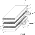
- the invention relates to an electrically conductive sandwich panel 10 to which electrical devices are intended to be electrically connected.
- electrical device means any device or apparatus intended to be supplied electrically such as a lighting device, an electrical outlet or a sensor.
- the sandwich panel 10 comprises a first layer 11 formed of a plate which comprises two sheets 111, 112 of cardboard trapping an electrically insulating material, such as plaster.
- the material of said plate can be cement or another material.
- Said panel also comprises a sixth layer 16 made of electrically insulating material, a second layer 12 made of electrically insulating material, a third layer 13 made of electrically conductive material, a fourth layer 14 made of electrically insulating material and a fifth layer 15 made of electrically conductive material.
- the electrically insulating material used to make the layers 12, 14 and 16 is a material which does not deform into a cone when it is stitched, unlike a sheet of cardboard for example.
- Said material can be a polyurethane or polystyrene foam.
- the material can also be of the wool type, for example glass wool or compressed rock wool.
- the material can also be fibrous, such as wood, especially balsa, or be a foam made from wood.
- Said material can also be a textile.
- the material is a so-called soft material whose density is less than 300 Kg / m3.
- the use of such a material makes it possible to easily insert, for example by hand, each power connector in the edge of the layers 12 and 14 or in the edge of the layers 14 and 16 of the panel.
- such a choice of materials makes it possible to insert each connector laterally in the panel in the manner of a thumbtack, without having to provide for a specific clearance within the panel and without risking damaging the connectors.
- the two electrically conductive layers 13, 15 are capable of forming two positive and negative (or phase and neutral) power supply tracks of a device electrical which includes two electrical contacts for its power supply.
- the two electrical contacts can be carried by the same pin 30 ( figure 2 ) or distributed over two pins 31, 32 ( figure 1 ). As detailed below, the or each pin is intended to be inserted into the panel 10 to bring one of the electrical contacts against the electrically conductive layer 13, and the other against the electrically conductive layer 15.
- the panel comprises at least one additional electrically conductive layer, which can be used to transmit a signal or be connected to earth.
- the tracks are intended to be connected by connectors 2 (detailed below) to an electrical supply, preferably a TBT or TBTS mains supply, for example a 12V supply.
- an electrical supply preferably a TBT or TBTS mains supply, for example a 12V supply.
- the SELV continuous supply can be carried out using a transformer connected to the SELV sector.
- the thickness of the electrically conductive layers 13 and 15 is less than the thickness of the other layers.
- the electrically conductive layers have in particular a thickness of less than 300 microns, and preferably have a thickness of the order of 100 to 200 microns.
- Said layers of the panel are bonded together.
- the layers 13 and 14, and 15 and 16 are bonded together by depositing lines of glue with a regular amount of glue along each line, to prevent an electrical contact area from a device pin electric crosses an area of excess adhesive and is thus electrically insulated from the electrically conductive layer with which said pin is intended to be in contact.
- a zone of excess adhesive thickness could form an insulation cone between the corresponding electrically conductive layer and the pin.
- Said lines of glue can be made in a straight and / or parallel manner, for example in a sinuous manner, without any point of inflection which would risk causing a larger local deposit of glue.
- Bonding is preferably carried out by a bonding process under hot pressure of the “hot melt” or hot-melt type, or cold bonding of the polyurethane adhesive type.
- the second layer 12 which isolates and separates the plate 11 from the electrically conductive layer 13 has a thickness less than that of each of the other layers 14, 16.
- the second layer 12 of electrically insulating material is of thickness at least equal to the diameter of the or each pin 30; 31, 32 of the electrical device 3 stitched into the panel to allow the cardboard sheet 112 to be maintained, which is deformed into a cone by the pin which passes through it, spaced from the electrically conductive layer 13.
- each of the electrically conductive layers 13, 15 comprises two metal sheets, preferably of aluminum, and a sheet of elastic material trapped between said metal sheets.
- each of the layers 13, 15 forms an elastic complex resembling the upper aluminum sheet against the pin which the cross member and thus promotes electrical contact between the corresponding contact carried by the pin and said electrically conductive layer.
- an electrical device preferably a lighting device 3, for example LED, is stitched on said sandwich panel 10.
- the electrical device comprises a pin 30 or two connection pins 31, 32 intended to be stitched into the panel 10.
- said pin carries two contacts 303, 305 at different heights being isolated from one another.
- the contacts 303, 305 are coaxial.
- the two contacts 303, 305 are intended to come respectively against the layers 13, 15 without touching the other layer 15, 13.
- the first pin 31 comprises a conductive portion 315 capable of coming into contact with the conductive layer 15 without being in electrical contact with the layer 13.
- the second pin 32 is capable of coming into contact contact with the conductive layer 13 without coming into electrical contact with the conductive layer 15.
- the absence of electrical contact between a pin and a given conductive layer can be achieved by designing the length of the pin so that in the pitted state, it crosses the other conductive layer but without reaching said given conductive layer (see the pin 32 of the figure 1 ) or so that the part of the pin which passes through said given conductive layer is electrically insulated (the part 313 of the pin 31 at the figure 1 is isolated from runway 13).
- the part of a pin intended to be insulated is provided with a coating which can be formed by a paint or insulating sheath, for example of rigid material.
- the sandwich panel 10 is further equipped with two connectors 2.
- One of the connectors 2 is able to connect one of the layers 13, 15 to one terminal of an electrical supply, and the other of the connectors is able to connect the other of the layers 13, 15 to the other terminal of the power supply.
- Each connector 2 has a U-shape.
- the free end of each branch 21, 22 is pointed and each branch 21, 22 of the U is split longitudinally from its free end to the connection zone between said branch 21, 22 and the bottom 20 of the U.
- Each layer 12, 14 and 16 has a sufficient thickness so that the branch of a connector can enter the thickness of said layer.
- Each connector can be equipped with a domino element to connect an electric wire at the level of the part forming the bottom of the U of the connector.
- the other end of the wire is connected to the power supply.
- said electrical wire can be soldered or crimped directly to the connector.
- Each branch 21, 22 of connector 2 is stitched on a edge of the sandwich panel 10 so that the branch portions which extend on either side of the slot 210, 220 of said branch are inserted respectively in the fourth and sixth layers 14, 16, or respectively in the second 12 and fourth 14 layers, which sandwich the third or fifth layer 13, 15 electrically conductive that the operator wishes to connect by said connector to the power supply.
- Each electrically conductive layer 13, 15 is taken in the slots 210, 220 of the corresponding connector 2 and in electrical contact with the corresponding slot edges.
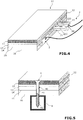
- the branches 21, 22 and the bottom 20 of the U of each connector are flat to allow it to be pushed in until the edge is pressed as illustrated in the figure 4 , and thus limit the size of the panel.
- said sandwich panel 10 can be fixed to a support 9, for example a metal rail or a wooden support such as a joist, using self-drilling screws 4.
- said screw 4 has a screw head and a metal body 40 which comprises a threaded end portion 42, and between said head and the threaded end portion, a smooth portion 41.
- the metal body 40 is preferably made of steel having undergone a heat treatment to make it self-drilling.
- Said smooth portion 41 has an electrically insulating coating, for example made of teflon or epoxy, preferably of a color different from that of the screw body 4 thus coated.
- Said coating is preferably in the form of a baked paint to prevent it from flaking. The color can be chosen white so as to allow visualization of a possible scratch which could degrade the electrical insulation of the smooth portion.
- the screw 4 has a diameter less than the thickness of the fourth layer 14, which makes it possible to prevent the fifth layer 15 from coming into contact by cone deformation with the third layer 13 during screwing.
- Said smooth portion 41 isolated from the screw 4 is of suitable length so as to pass through the third and fifth layers 13, 15 electrically conductive, while leaving part of the thread of the screw engaged in the sixth layer 16 to hold the sandwich panel 10 in abutment against the support 9 in which the screw 4 is taken.
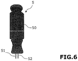
- the punching tool 5 comprises a gripping body 50 intended to be gripped by the hand of an operator, and one or two punches 51, 52 pointed at their free end and of elongated shape.
- the length of each punch is adapted to pass through the thickness of the plasterboard, in particular the rigid material caught between the sheets of cardboard.
- the gripping body 50 is elongated and of generally cylindrical shape.
- said punches are of the same length and extending parallel to one another from the face of the gripping body intended to be directed towards the panel.
- the axis of the grip body is parallel to the axis of each punch.
- the diameter of the punches 51, 52 is greater than or equal to the diameter of the pin or pins of the electrical device.
- the punching tool can thus be used to pre-drill the panel from the plate and subsequently insert the pin or pins of the electrical device into the panel, which is particularly advantageous when the two pins are not of the same length. Indeed, a stitching without pre-drilling with such an electrical device would risk bending the pins.
Landscapes
- Engineering & Computer Science (AREA)
- Architecture (AREA)
- Structural Engineering (AREA)
- Civil Engineering (AREA)
- Life Sciences & Earth Sciences (AREA)
- Wood Science & Technology (AREA)
- General Engineering & Computer Science (AREA)
- Coupling Device And Connection With Printed Circuit (AREA)
- Laminated Bodies (AREA)
- Installation Of Indoor Wiring (AREA)
- Mechanical Engineering (AREA)
Claims (14)
- Elektrisch leitende Sandwichplatte (10), dadurch gekennzeichnet, dass die Sandwichplatte (10) in der folgenden Reihenfolge umfasst:- eine erste Schicht (11), gebildet von einer Tafel, die zwei Kartonbögen (111, 112) umfasst, die ein elektrisch isolierendes Material wie Gips einschließen;- eine zweite Schicht (12) aus elektrisch isolierendem Material;- eine dritte Schicht (13) aus elektrisch leitendem Material;- eine vierte Schicht (14) aus elektrisch isolierendem Material;- eine fünfte Schicht (15) aus elektrisch leitendem Material;- eine sechste Schicht (16) aus elektrisch isolierendem Material.
- Sandwichplatte (10) nach Anspruch 1, dadurch gekennzeichnet, dass die zweite und dritte Schicht (12, 13) sowie die vierte und fünfte Schicht (14, 15) durch Aufbringen von Klebelinien mit einer gleichmäßigen Menge Klebstoff entlang jeder Linie untereinander verklebt sind.
- Sandwichplatte (10) nach einem der vorangehenden Ansprüche, dadurch gekennzeichnet, dass mindestens eine, vorzugsweise jede der elektrisch leitenden Schichten (13, 15) zwei Metallbögen, vorzugsweise aus Aluminium, und einen Bogen aus elastischem Material, der zwischen den Metallbögen eingeschlossen ist, umfasst.
- Sandwichplatte (10) nach einem der vorangehenden Ansprüche, dadurch gekennzeichnet, dass die Sandwichplatte (10) mit mindestens einer elektrischen Vorrichtung, vorzugsweise einer Beleuchtungsvorrichtung (3), beispielsweise mit LED, ausgestattet ist, die einen oder zwei Kontaktstifte (31, 32) umfasst, der/die dazu vorgesehen ist/sind, in die Platte (10) gesteckt zu sein und zwei elektrische Kontakte trägt/tragen, wobei die zwei elektrischen Kontakte über den oder jeden der Stifte (31, 32) derart verteilt sind, dass im gesteckten Zustand des oder der Stifte in die Platte (10) einer der elektrischen Kontakte eine der elektrisch leitenden Schichten (13, 15) berührt, ohne die andere Schicht (15, 13) zu berühren, die von dem anderen elektrischen Kontakt berührt wird.
- Sandwichplatte (10) nach Anspruch 4, dadurch gekennzeichnet, dass die zweite Schicht (12) aus elektrisch isolierendem Material eine Stärke hat, die mindestens gleich dem Durchmesser des oder jedes in die Platte gesteckten Stifts (30; 31, 32) der elektrischen Vorrichtung (3) ist.
- Sandwichplatte (10) nach einem der vorangehenden Ansprüche, dadurch gekennzeichnet, dass die Sandwichplatte (10) ferner mit zwei Verbindern (2) ausgestattet ist, wobei einer der Verbinder imstande ist, eine der elektrisch leitenden Schichten (13, 15) mit einer Klemme einer elektrischen Versorgung zu verbinden, und der andere der Verbinder imstande ist, die andere der elektrisch leitenden Schichten (13, 15) mit der anderen Klemme der elektrischen Versorgung zu verbinden,
und dass jeder Verbinder (2) eine U-Form aufweist, wobei das freie Ende jedes Schenkels (21, 22) spitz ist und jeder Schenkel (21, 22) des U ab seinem freien Ende bis zu einer Verbindungszone zwischen dem Schenkel (21, 22) und dem Boden (20) des U längs (210, 220) geschlitzt ist. - Sandwichplatte (10) nach Anspruch 6, dadurch gekennzeichnet, dass jeder Schenkel (21, 22) eines Verbinders (2) derart auf eine Kante der Sandwichplatte (10) gesteckt ist, dass die Schenkelabschnitte, die sich auf der einen und der anderen Seite der Kante erstrecken, jeweils in die vierte und sechste Schicht (14, 16) oder jeweils in die zweite (12) und vierte (14) Schicht eingedrückt sind, welche die dritte oder fünfte elektrisch leitende Schicht (13, 15) sandwichartig umschließen, wobei die dritte oder fünfte elektrisch leitende Schicht (13, 15) in dem Schlitz aufgenommen und in elektrischem Kontakt mit den entsprechenden Schlitzrändern ist.
- Sandwichplatte (10) nach Anspruch 7, dadurch gekennzeichnet, dass das Material der zweiten (12), vierten (14) und sechsten Schicht (16) eine Dichte unter 300 kg/m3 hat.
- Sandwichplatte (10) nach Anspruch 8, dadurch gekennzeichnet, dass die Schenkel (21, 22) und der Boden (20) des U, das jeder Verbinder (2) bildet, flach sind.
- Sandwichplatte (10) nach einem der vorangehenden Ansprüche, dadurch gekennzeichnet, dass die Sandwichplatte (10) ferner mit Befestigungsmitteln der Sandwichplatte (10) auf einem Träger (9) ausgestattet ist, wobei die Befestigungsmittel eine selbstschneidende Schraube (4) umfassen, die einen Schraubenkopf und einen metallischen Körper (40), umfassend einen gewindeten Endabschnitt (42), aufweist, und zwischen dem Kopf und dem gewindeten Endabschnitt einen glatten Abschnitt (41), wobei der glatte Abschnitt (41) eine elektrisch isolierende Beschichtung, beispielsweise aus Teflon oder Epoxy, vorzugsweise in unterschiedlicher Farbe als die des so beschichteten Schraubenkörpers (4), umfasst.
- Sandwichplatte (10) nach Anspruch 10, dadurch gekennzeichnet, dass die Schraube (4) einen Durchmesser aufweist, der kleiner als die Stärke der vierten Schicht (14) ist.
- Sandwichplatte (10) nach Anspruch 10 oder 11, dadurch gekennzeichnet, dass der glatte Abschnitt (41) eine Länge hat, die geeignet ist, die elektrisch leitenden Schichten (13, 15) zu durchqueren, wobei ein Teil des Gewindes der Schraube in der sechsten Schicht (16) verbleibt, um die Sandwichplatte (10) abgestützt auf dem Träger (9) zu halten, in welchem die Schraube (4) aufgenommen ist.
- Einheit, umfassend:- eine Sandwichplatte (10) nach einem der vorangehenden Ansprüche,- mindestens eine elektrische Vorrichtung (3), die einen oder zwei Kontaktstifte (31, 32) umfasst, der/die bestimmt ist/sind, in die Sandwichplatte (10) gesteckt zu sein, und- ein Lochwerkzeug (5), umfassend einen Griffkörper (50), der bestimmt ist, von der Hand eines Bedieners ergriffen zu sein, und eine oder zwei Ahlen (51, 52) derselben Länge, die an ihrem freien Ende spitz und länglich geformt sind.
- Einheit nach Anspruch 13, dadurch gekennzeichnet, dass der Durchmesser der Ahlen (51, 52) größer oder gleich dem Durchmesser des oder der Stifte (31, 32) der elektrischen Vorrichtung (3) ist.
Applications Claiming Priority (2)
| Application Number | Priority Date | Filing Date | Title |
|---|---|---|---|
| FR1554618A FR3036309B1 (fr) | 2015-05-22 | 2015-05-22 | Panneau sandwich electriquement conducteur |
| PCT/FR2016/051199 WO2016189236A1 (fr) | 2015-05-22 | 2016-05-20 | Panneau sandwich electriquement conducteur |
Publications (2)
| Publication Number | Publication Date |
|---|---|
| EP3297828A1 EP3297828A1 (de) | 2018-03-28 |
| EP3297828B1 true EP3297828B1 (de) | 2020-03-18 |
Family
ID=53496869
Family Applications (1)
| Application Number | Title | Priority Date | Filing Date |
|---|---|---|---|
| EP16731218.0A Active EP3297828B1 (de) | 2015-05-22 | 2016-05-20 | Elektrisch leitende sandwichplatte |
Country Status (4)
| Country | Link |
|---|---|
| US (1) | US10502405B2 (de) |
| EP (1) | EP3297828B1 (de) |
| FR (1) | FR3036309B1 (de) |
| WO (1) | WO2016189236A1 (de) |
Family Cites Families (5)
| Publication number | Priority date | Publication date | Assignee | Title |
|---|---|---|---|---|
| DE10300857A1 (de) * | 2003-01-10 | 2004-07-29 | Vossloh-Wustlich Opto Gmbh & Co.Kg | Plattenartiges Bekleidungselement, insbesondere für Wände, Decken oder Böden von Gebäuden, und daraus hergestellte Bekleidung |
| DE202004011454U1 (de) * | 2004-07-21 | 2004-09-23 | Hutzenlaub, Jens | Flächiges Bauelement zur einfachen Montage von Leuchtdioden |
| WO2007006147A1 (en) | 2005-07-14 | 2007-01-18 | Tir Systems Ltd. | Power board and plug-in lighting module |
| DE102012013831B4 (de) * | 2012-07-13 | 2019-08-22 | Lohmann Gmbh & Co. Kg | LED-Board |
| US9332632B2 (en) * | 2014-08-20 | 2016-05-03 | Stablcor Technology, Inc. | Graphene-based thermal management cores and systems and methods for constructing printed wiring boards |
-
2015
- 2015-05-22 FR FR1554618A patent/FR3036309B1/fr not_active Expired - Fee Related
-
2016
- 2016-05-20 WO PCT/FR2016/051199 patent/WO2016189236A1/fr not_active Ceased
- 2016-05-20 US US15/574,725 patent/US10502405B2/en active Active
- 2016-05-20 EP EP16731218.0A patent/EP3297828B1/de active Active
Non-Patent Citations (1)
| Title |
|---|
| None * |
Also Published As
| Publication number | Publication date |
|---|---|
| US10502405B2 (en) | 2019-12-10 |
| FR3036309A1 (fr) | 2016-11-25 |
| WO2016189236A1 (fr) | 2016-12-01 |
| US20180135844A1 (en) | 2018-05-17 |
| FR3036309B1 (fr) | 2017-06-16 |
| EP3297828A1 (de) | 2018-03-28 |
Similar Documents
| Publication | Publication Date | Title |
|---|---|---|
| WO2012010662A3 (fr) | Procede d'assemblage par collage direct entre deux elements comprenant des portions de cuivre et de materiaux dielectriques | |
| FR2953677A1 (fr) | Vitrage a fils conducteurs integres par ultrasons | |
| EP3297828B1 (de) | Elektrisch leitende sandwichplatte | |
| EP0262022A1 (de) | Rohrleitungen für eine zentrale Absaug-Säuberungsanlage und Verfahren zur Herstellung eines Rohres in derartigen Rohrleitungen | |
| EP3227966B1 (de) | Elektrisches verbindungselement, das einen stromdrahtisolierungsmantel penetriert | |
| CA2993755A1 (fr) | Piece evolutive comprenant une cloison connectable electriquement a un mur ou a un plafond | |
| EP2554893B1 (de) | LED-Lampenvorrichtung und automatisiertes Herstellungsverfahren dieser Vorrichtung | |
| EP3162980B1 (de) | Verstrebungsvorrichtung für die verkleidung einer struktur | |
| EP3286497B1 (de) | Planare montagevorrichtung mit beleuchtung | |
| FR2942083A1 (fr) | Dispositif pour la fixation d'elements souples dans un milieu peu accessible | |
| EP0181362B1 (de) | Elektrische steckdosenverbindungselemente und deren herstellungsverfahren | |
| FR2792041A1 (fr) | Systeme d'assemblage de panneaux de bois | |
| AU2003246641A1 (en) | Method for joining lacquered wires in an electrically conducting manner | |
| EP3349305B1 (de) | Verbessertes elektrisches anschlusskit | |
| FR3054403A1 (fr) | Vitrage avec element electriquement conducteur et sa connexion electrique | |
| EP2439815A1 (de) | Elektrische Verbindungsvorrichtung, insbesondere für einen Kabelkanal bestimmt | |
| EP3099148B1 (de) | Gedruckter schaltkreis, der ein gelenk umfasst | |
| EP0708493B1 (de) | Anschlussklemme mit selbstabisolierender, mittels einer Schraube betätigbarer Verbindungsvorrichtung | |
| FR3053168A1 (fr) | Connecteur de raccordement | |
| EP3336967A1 (de) | Elektrisches anschlusselement | |
| FR3029675A1 (fr) | Panneau d'affichage lumineux | |
| CN101311434A (zh) | 石材连接结构 | |
| EP3089171B1 (de) | Flache stromversorgungsleitung, entsprechendes versorgungsnetz und entsprechendes herstellungsverfahren | |
| WO2015086650A1 (fr) | Dispositif de maintien d'une presse contre un objet | |
| FR3028675A1 (fr) | Agencement pour empecher la rotation d'une cosse electrique et procede de fabrication correspondant. |
Legal Events
| Date | Code | Title | Description |
|---|---|---|---|
| STAA | Information on the status of an ep patent application or granted ep patent |
Free format text: STATUS: THE INTERNATIONAL PUBLICATION HAS BEEN MADE |
|
| PUAI | Public reference made under article 153(3) epc to a published international application that has entered the european phase |
Free format text: ORIGINAL CODE: 0009012 |
|
| STAA | Information on the status of an ep patent application or granted ep patent |
Free format text: STATUS: REQUEST FOR EXAMINATION WAS MADE |
|
| 17P | Request for examination filed |
Effective date: 20171115 |
|
| AK | Designated contracting states |
Kind code of ref document: A1 Designated state(s): AL AT BE BG CH CY CZ DE DK EE ES FI FR GB GR HR HU IE IS IT LI LT LU LV MC MK MT NL NO PL PT RO RS SE SI SK SM TR |
|
| AX | Request for extension of the european patent |
Extension state: BA ME |
|
| DAV | Request for validation of the european patent (deleted) | ||
| DAX | Request for extension of the european patent (deleted) | ||
| STAA | Information on the status of an ep patent application or granted ep patent |
Free format text: STATUS: EXAMINATION IS IN PROGRESS |
|
| 17Q | First examination report despatched |
Effective date: 20181114 |
|
| GRAP | Despatch of communication of intention to grant a patent |
Free format text: ORIGINAL CODE: EPIDOSNIGR1 |
|
| STAA | Information on the status of an ep patent application or granted ep patent |
Free format text: STATUS: GRANT OF PATENT IS INTENDED |
|
| INTG | Intention to grant announced |
Effective date: 20191010 |
|
| GRAS | Grant fee paid |
Free format text: ORIGINAL CODE: EPIDOSNIGR3 |
|
| GRAA | (expected) grant |
Free format text: ORIGINAL CODE: 0009210 |
|
| STAA | Information on the status of an ep patent application or granted ep patent |
Free format text: STATUS: THE PATENT HAS BEEN GRANTED |
|
| AK | Designated contracting states |
Kind code of ref document: B1 Designated state(s): AL AT BE BG CH CY CZ DE DK EE ES FI FR GB GR HR HU IE IS IT LI LT LU LV MC MK MT NL NO PL PT RO RS SE SI SK SM TR |
|
| REG | Reference to a national code |
Ref country code: GB Ref legal event code: FG4D Free format text: NOT ENGLISH |
|
| REG | Reference to a national code |
Ref country code: DE Ref legal event code: R096 Ref document number: 602016032030 Country of ref document: DE |
|
| REG | Reference to a national code |
Ref country code: AT Ref legal event code: REF Ref document number: 1245461 Country of ref document: AT Kind code of ref document: T Effective date: 20200415 Ref country code: IE Ref legal event code: FG4D Free format text: LANGUAGE OF EP DOCUMENT: FRENCH |
|
| PG25 | Lapsed in a contracting state [announced via postgrant information from national office to epo] |
Ref country code: NO Free format text: LAPSE BECAUSE OF FAILURE TO SUBMIT A TRANSLATION OF THE DESCRIPTION OR TO PAY THE FEE WITHIN THE PRESCRIBED TIME-LIMIT Effective date: 20200618 Ref country code: FI Free format text: LAPSE BECAUSE OF FAILURE TO SUBMIT A TRANSLATION OF THE DESCRIPTION OR TO PAY THE FEE WITHIN THE PRESCRIBED TIME-LIMIT Effective date: 20200318 Ref country code: RS Free format text: LAPSE BECAUSE OF FAILURE TO SUBMIT A TRANSLATION OF THE DESCRIPTION OR TO PAY THE FEE WITHIN THE PRESCRIBED TIME-LIMIT Effective date: 20200318 |
|
| REG | Reference to a national code |
Ref country code: NL Ref legal event code: MP Effective date: 20200318 |
|
| PG25 | Lapsed in a contracting state [announced via postgrant information from national office to epo] |
Ref country code: BG Free format text: LAPSE BECAUSE OF FAILURE TO SUBMIT A TRANSLATION OF THE DESCRIPTION OR TO PAY THE FEE WITHIN THE PRESCRIBED TIME-LIMIT Effective date: 20200618 Ref country code: GR Free format text: LAPSE BECAUSE OF FAILURE TO SUBMIT A TRANSLATION OF THE DESCRIPTION OR TO PAY THE FEE WITHIN THE PRESCRIBED TIME-LIMIT Effective date: 20200619 Ref country code: LV Free format text: LAPSE BECAUSE OF FAILURE TO SUBMIT A TRANSLATION OF THE DESCRIPTION OR TO PAY THE FEE WITHIN THE PRESCRIBED TIME-LIMIT Effective date: 20200318 Ref country code: SE Free format text: LAPSE BECAUSE OF FAILURE TO SUBMIT A TRANSLATION OF THE DESCRIPTION OR TO PAY THE FEE WITHIN THE PRESCRIBED TIME-LIMIT Effective date: 20200318 Ref country code: HR Free format text: LAPSE BECAUSE OF FAILURE TO SUBMIT A TRANSLATION OF THE DESCRIPTION OR TO PAY THE FEE WITHIN THE PRESCRIBED TIME-LIMIT Effective date: 20200318 |
|
| REG | Reference to a national code |
Ref country code: LT Ref legal event code: MG4D |
|
| PG25 | Lapsed in a contracting state [announced via postgrant information from national office to epo] |
Ref country code: NL Free format text: LAPSE BECAUSE OF FAILURE TO SUBMIT A TRANSLATION OF THE DESCRIPTION OR TO PAY THE FEE WITHIN THE PRESCRIBED TIME-LIMIT Effective date: 20200318 |
|
| PG25 | Lapsed in a contracting state [announced via postgrant information from national office to epo] |
Ref country code: LT Free format text: LAPSE BECAUSE OF FAILURE TO SUBMIT A TRANSLATION OF THE DESCRIPTION OR TO PAY THE FEE WITHIN THE PRESCRIBED TIME-LIMIT Effective date: 20200318 Ref country code: RO Free format text: LAPSE BECAUSE OF FAILURE TO SUBMIT A TRANSLATION OF THE DESCRIPTION OR TO PAY THE FEE WITHIN THE PRESCRIBED TIME-LIMIT Effective date: 20200318 Ref country code: IS Free format text: LAPSE BECAUSE OF FAILURE TO SUBMIT A TRANSLATION OF THE DESCRIPTION OR TO PAY THE FEE WITHIN THE PRESCRIBED TIME-LIMIT Effective date: 20200718 Ref country code: SK Free format text: LAPSE BECAUSE OF FAILURE TO SUBMIT A TRANSLATION OF THE DESCRIPTION OR TO PAY THE FEE WITHIN THE PRESCRIBED TIME-LIMIT Effective date: 20200318 Ref country code: CZ Free format text: LAPSE BECAUSE OF FAILURE TO SUBMIT A TRANSLATION OF THE DESCRIPTION OR TO PAY THE FEE WITHIN THE PRESCRIBED TIME-LIMIT Effective date: 20200318 Ref country code: PT Free format text: LAPSE BECAUSE OF FAILURE TO SUBMIT A TRANSLATION OF THE DESCRIPTION OR TO PAY THE FEE WITHIN THE PRESCRIBED TIME-LIMIT Effective date: 20200812 Ref country code: EE Free format text: LAPSE BECAUSE OF FAILURE TO SUBMIT A TRANSLATION OF THE DESCRIPTION OR TO PAY THE FEE WITHIN THE PRESCRIBED TIME-LIMIT Effective date: 20200318 Ref country code: SM Free format text: LAPSE BECAUSE OF FAILURE TO SUBMIT A TRANSLATION OF THE DESCRIPTION OR TO PAY THE FEE WITHIN THE PRESCRIBED TIME-LIMIT Effective date: 20200318 |
|
| REG | Reference to a national code |
Ref country code: AT Ref legal event code: MK05 Ref document number: 1245461 Country of ref document: AT Kind code of ref document: T Effective date: 20200318 |
|
| REG | Reference to a national code |
Ref country code: DE Ref legal event code: R097 Ref document number: 602016032030 Country of ref document: DE |
|
| PLBE | No opposition filed within time limit |
Free format text: ORIGINAL CODE: 0009261 |
|
| STAA | Information on the status of an ep patent application or granted ep patent |
Free format text: STATUS: NO OPPOSITION FILED WITHIN TIME LIMIT |
|
| PG25 | Lapsed in a contracting state [announced via postgrant information from national office to epo] |
Ref country code: IT Free format text: LAPSE BECAUSE OF FAILURE TO SUBMIT A TRANSLATION OF THE DESCRIPTION OR TO PAY THE FEE WITHIN THE PRESCRIBED TIME-LIMIT Effective date: 20200318 Ref country code: MC Free format text: LAPSE BECAUSE OF FAILURE TO SUBMIT A TRANSLATION OF THE DESCRIPTION OR TO PAY THE FEE WITHIN THE PRESCRIBED TIME-LIMIT Effective date: 20200318 Ref country code: AT Free format text: LAPSE BECAUSE OF FAILURE TO SUBMIT A TRANSLATION OF THE DESCRIPTION OR TO PAY THE FEE WITHIN THE PRESCRIBED TIME-LIMIT Effective date: 20200318 Ref country code: DK Free format text: LAPSE BECAUSE OF FAILURE TO SUBMIT A TRANSLATION OF THE DESCRIPTION OR TO PAY THE FEE WITHIN THE PRESCRIBED TIME-LIMIT Effective date: 20200318 Ref country code: ES Free format text: LAPSE BECAUSE OF FAILURE TO SUBMIT A TRANSLATION OF THE DESCRIPTION OR TO PAY THE FEE WITHIN THE PRESCRIBED TIME-LIMIT Effective date: 20200318 |
|
| 26N | No opposition filed |
Effective date: 20201221 |
|
| PG25 | Lapsed in a contracting state [announced via postgrant information from national office to epo] |
Ref country code: PL Free format text: LAPSE BECAUSE OF FAILURE TO SUBMIT A TRANSLATION OF THE DESCRIPTION OR TO PAY THE FEE WITHIN THE PRESCRIBED TIME-LIMIT Effective date: 20200318 |
|
| PG25 | Lapsed in a contracting state [announced via postgrant information from national office to epo] |
Ref country code: LU Free format text: LAPSE BECAUSE OF NON-PAYMENT OF DUE FEES Effective date: 20200520 |
|
| PG25 | Lapsed in a contracting state [announced via postgrant information from national office to epo] |
Ref country code: IE Free format text: LAPSE BECAUSE OF NON-PAYMENT OF DUE FEES Effective date: 20200520 |
|
| PG25 | Lapsed in a contracting state [announced via postgrant information from national office to epo] |
Ref country code: SI Free format text: LAPSE BECAUSE OF FAILURE TO SUBMIT A TRANSLATION OF THE DESCRIPTION OR TO PAY THE FEE WITHIN THE PRESCRIBED TIME-LIMIT Effective date: 20200318 |
|
| PG25 | Lapsed in a contracting state [announced via postgrant information from national office to epo] |
Ref country code: TR Free format text: LAPSE BECAUSE OF FAILURE TO SUBMIT A TRANSLATION OF THE DESCRIPTION OR TO PAY THE FEE WITHIN THE PRESCRIBED TIME-LIMIT Effective date: 20200318 Ref country code: MT Free format text: LAPSE BECAUSE OF FAILURE TO SUBMIT A TRANSLATION OF THE DESCRIPTION OR TO PAY THE FEE WITHIN THE PRESCRIBED TIME-LIMIT Effective date: 20200318 Ref country code: CY Free format text: LAPSE BECAUSE OF FAILURE TO SUBMIT A TRANSLATION OF THE DESCRIPTION OR TO PAY THE FEE WITHIN THE PRESCRIBED TIME-LIMIT Effective date: 20200318 |
|
| PG25 | Lapsed in a contracting state [announced via postgrant information from national office to epo] |
Ref country code: MK Free format text: LAPSE BECAUSE OF FAILURE TO SUBMIT A TRANSLATION OF THE DESCRIPTION OR TO PAY THE FEE WITHIN THE PRESCRIBED TIME-LIMIT Effective date: 20200318 Ref country code: AL Free format text: LAPSE BECAUSE OF FAILURE TO SUBMIT A TRANSLATION OF THE DESCRIPTION OR TO PAY THE FEE WITHIN THE PRESCRIBED TIME-LIMIT Effective date: 20200318 |
|
| PGFP | Annual fee paid to national office [announced via postgrant information from national office to epo] |
Ref country code: DE Payment date: 20250530 Year of fee payment: 10 |
|
| PGFP | Annual fee paid to national office [announced via postgrant information from national office to epo] |
Ref country code: GB Payment date: 20250530 Year of fee payment: 10 |
|
| PGFP | Annual fee paid to national office [announced via postgrant information from national office to epo] |
Ref country code: BE Payment date: 20250530 Year of fee payment: 10 |
|
| PGFP | Annual fee paid to national office [announced via postgrant information from national office to epo] |
Ref country code: FR Payment date: 20250530 Year of fee payment: 10 |
|
| PGFP | Annual fee paid to national office [announced via postgrant information from national office to epo] |
Ref country code: CH Payment date: 20250606 Year of fee payment: 10 |