EP3297397B1 - Procédé de fonctionnement d'une plaque de cuisson dotée d'une pluralité de dispositifs de chauffage - Google Patents
Procédé de fonctionnement d'une plaque de cuisson dotée d'une pluralité de dispositifs de chauffage Download PDFInfo
- Publication number
- EP3297397B1 EP3297397B1 EP17190630.8A EP17190630A EP3297397B1 EP 3297397 B1 EP3297397 B1 EP 3297397B1 EP 17190630 A EP17190630 A EP 17190630A EP 3297397 B1 EP3297397 B1 EP 3297397B1
- Authority
- EP
- European Patent Office
- Prior art keywords
- power density
- area power
- cooking vessel
- heating
- cooktop
- Prior art date
- Legal status (The legal status is an assumption and is not a legal conclusion. Google has not performed a legal analysis and makes no representation as to the accuracy of the status listed.)
- Active
Links
- 238000010438 heat treatment Methods 0.000 title claims description 80
- 238000010411 cooking Methods 0.000 title claims description 74
- 238000000034 method Methods 0.000 title claims description 23
- 238000006073 displacement reaction Methods 0.000 claims description 26
- 238000001514 detection method Methods 0.000 claims description 4
- 230000011664 signaling Effects 0.000 claims description 3
- 230000003287 optical effect Effects 0.000 claims 1
- 230000006698 induction Effects 0.000 description 13
- XLYOFNOQVPJJNP-UHFFFAOYSA-N water Substances O XLYOFNOQVPJJNP-UHFFFAOYSA-N 0.000 description 4
- 230000000694 effects Effects 0.000 description 2
- 235000015927 pasta Nutrition 0.000 description 2
- 238000009835 boiling Methods 0.000 description 1
- 238000006243 chemical reaction Methods 0.000 description 1
- 238000009998 heat setting Methods 0.000 description 1
- 230000000717 retained effect Effects 0.000 description 1
Images
Classifications
-
- H—ELECTRICITY
- H05—ELECTRIC TECHNIQUES NOT OTHERWISE PROVIDED FOR
- H05B—ELECTRIC HEATING; ELECTRIC LIGHT SOURCES NOT OTHERWISE PROVIDED FOR; CIRCUIT ARRANGEMENTS FOR ELECTRIC LIGHT SOURCES, IN GENERAL
- H05B6/00—Heating by electric, magnetic or electromagnetic fields
- H05B6/02—Induction heating
- H05B6/06—Control, e.g. of temperature, of power
- H05B6/062—Control, e.g. of temperature, of power for cooking plates or the like
-
- H—ELECTRICITY
- H05—ELECTRIC TECHNIQUES NOT OTHERWISE PROVIDED FOR
- H05B—ELECTRIC HEATING; ELECTRIC LIGHT SOURCES NOT OTHERWISE PROVIDED FOR; CIRCUIT ARRANGEMENTS FOR ELECTRIC LIGHT SOURCES, IN GENERAL
- H05B2213/00—Aspects relating both to resistive heating and to induction heating, covered by H05B3/00 and H05B6/00
- H05B2213/03—Heating plates made out of a matrix of heating elements that can define heating areas adapted to cookware randomly placed on the heating plate
-
- H—ELECTRICITY
- H05—ELECTRIC TECHNIQUES NOT OTHERWISE PROVIDED FOR
- H05B—ELECTRIC HEATING; ELECTRIC LIGHT SOURCES NOT OTHERWISE PROVIDED FOR; CIRCUIT ARRANGEMENTS FOR ELECTRIC LIGHT SOURCES, IN GENERAL
- H05B2213/00—Aspects relating both to resistive heating and to induction heating, covered by H05B3/00 and H05B6/00
- H05B2213/05—Heating plates with pan detection means
Definitions
- the invention relates to a method for operating a hob, this hob having a plurality of heating devices under a hob plate.
- the invention is based on the object of creating a method mentioned at the beginning with which a hob with a hob plate and several or with a plurality of heating devices can advantageously be operated, in particular in the event that a cooking vessel is to be moved on the hob plate and should continue to be heated.
- This object is achieved by a method having the features of claim 1.
- Advantageous and preferred embodiments of the invention are the subject matter of the further claims and are explained in more detail below. The wording of the claims is made part of the content of the description by express reference.
- the hob which is to be operated with the method according to the invention has a hob plate and a large number of heating devices are arranged underneath.
- the heating devices advantageously adjoin one another and / or are provided in a regular arrangement so that they cover a substantial part of the area under the hob plate, in particular a so-called heating area.
- Such hobs are for example from the aforementioned EP 2211591 A1 or the DE 102014224051 A1 known.
- a cooking vessel is placed on the hob plate in a first position, the cooking vessel covering at least one heating device. It advantageously covers at least two heating devices in such a way that both heating devices are operated.
- this at least one heating device is operated with a certain predetermined first surface power density in order to heat the cooking vessel or its contents.
- This predetermined first surface power density is usually entered as a power level when entered manually by an operator on an operating device of the hob, alternatively by means of a remote control for the hob.
- a first surface power density could also be specified by an automatic cooking program.
- the cooking vessel is moved on the hob plate, for example deliberately by an operator, because the current position may be perceived as disturbing or unnecessary.
- a displacement of the cooking vessel must take place by a certain minimum displacement path so that the method runs or makes sense. This can be at least 5 cm, for example.
- the cooking vessel is then in a second position which differs from the first position in terms of this minimum displacement.
- the future surface power density with which the cooking vessel is heated is then determined as a function of the previously described, predetermined and currently or previously used first surface power density for the at least one heating device. It is therefore determined with which future surface power density the cooking vessel is heated in the second position. There are at least two cases.
- the previous heating of the cooking vessel took place with a so-called small area power density as the first area power density.
- a small area power density is advantageously equal to and less than 3.5 W / cm 2 , under certain circumstances even less than 3 W / cm 2 or 2.5 W / cm 2 .
- 3.5 W / cm 2 usually correspond to level 7 as the power level or level on an induction hob.
- the cooking vessel is also heated at the second position with the previous first surface power density, so it is retained.
- the heating of the cooking vessel does not change or changes only insignificantly, namely possibly depending on negligible parameters such as the coverage of one or more heating devices. In principle, this should also be independent of whether the cooking vessel is heated by one or more heating devices in the first position or in the second position, because it covers these differently.
- the aim of the invention is to ensure that in this first case, i.e. when the cooking vessel is previously heated with a small surface power density in the first position, this heating with a small surface power density is also continued in the new second position, in particular is continued permanently.
- the cooking vessel was heated with a high surface power density as the first surface power density after it was set up, and this is then reduced, in particular permanently reduced, after the cooking vessel has been moved into the second position.
- the second area power density here is therefore less than the specified first and large area power density.
- Such a large area power density can advantageously be greater than the previously mentioned 3.5 W / cm 2 or greater than 45% of the maximum area power density as a distinguishing value or limit value. It can also only be present at even higher values, for example at 4 W / cm 2 or even only at 5 W / cm 2 , that is to say at 50% to 60% of the maximum surface power density.
- the heating power or the surface power density or the power or cooking level is reduced after the shift.
- the invention has found that, in practice, when the cooking vessel is heated to such a large or very large or even only at the maximum surface power density, a cooking vessel is then moved if an undesired or critical condition is present: for example, water for pasta or water with pasta boiled over in it, or a steak is seared too much in a pan or threatens to burn.
- an undesired or critical condition for example, water for pasta or water with pasta boiled over in it, or a steak is seared too much in a pan or threatens to burn.
- moving the cooking vessel away from the complete covering of the heating device can result in a clear or complete Reduction of the heating power can be effected.
- the cooking vessel is, so to speak, removed from the hotplate. In the second case of the invention, this behavior is to be simulated or reproduced, so to speak, which is why in this second case the surface power density is reduced.
- a reduction in the area power density in the aforementioned second case i.e. if a large predetermined first area power density was used at the beginning, to a new or future area power density between 0.5 W / cm 2 and 4 W / cm 2 or 1.0 W / cm 2 and 4 W / cm 2 , particularly advantageously between 1.5 W / cm 2 and 2.5 W / cm 2 .
- the area power density can be reduced to or below the limit value described above, from which a distinction is made between either a small area power density or a large area power density.
- a reduction in the surface power density takes place even more in this second case, in particular even below the mentioned first surface power density or below the limit value. As a result, a previously described critical or undesired state can be eliminated in any case.
- the aforementioned small surface power density is even below 3.5 W / cm 2 . It can also be only 1.5 W / cm 2 or 2.5 W / cm 2 , corresponding to a level 5 or 6 as the power level or cooking level.
- the minimum displacement path mentioned can advantageously be greater than 5 cm, particularly advantageously greater than 10 cm.
- a shift direction can generally be neglected. This means that it can be taken into account that several cooking vessels can stand on the hob when in use and that it is not always possible to move them backwards, which is probably the most common and simplest case, but may also have to be done at an angle to the rear, possibly even afterwards front. In one embodiment of the invention, however, it could also be provided that the direction of displacement affects the amount and / or duration of the power reduction.
- the small surface power density and the large surface power density directly adjoin one another without a further power range for a surface power density in between, that is to say are only separated by a single fixed limit value.
- a very small surface power density or a very large surface power density can possibly be provided below or even above it.
- a signal is particularly advantageously given to an operator by the hob when the displacement of the cooking vessel by at least the aforementioned minimum displacement has been determined.
- Such signaling can take place optically and / or acoustically.
- a signaling can take place in a similar form if, depending on the distinction in the first or the second case, the area power density has been maintained or has been reduced.
- an operator is offered an option of the area power density determine, especially about the takeover or not.
- This option can be offered for a certain offer time, in particular 1 sec to 10 sec.
- an operator input in particular on an aforementioned operator control device of the hob, can confirm or prevent a power takeover of the previous first surface power density or the setting of a new second surface power density.
- an operator can receive a request, advantageously optically and / or acoustically, to accept or reject a future area power density shown by the hob on a display in the form of a cooking level as suggested by the hob.
- a request advantageously optically and / or acoustically, to accept or reject a future area power density shown by the hob on a display in the form of a cooking level as suggested by the hob.
- the cooking vessel in the second position is first heated with the above-described reduced surface power density.
- account can be taken of the fact that in the above-described urgent case or, so to speak, an emergency, a power reduction takes place immediately, as an operator is used to with normal conventional hobs with individual heating devices.
- the displacement of the cooking vessel is not based on such an undesired or dangerous state, but has taken place for other reasons, which above all also mean that the cooking vessel should continue to be heated with the large or even a very large surface power density, so can possibly with a single operating process or a one-time triggering of an operating element, for example by operating an operating element, the previous first high surface power density again during the offer time can be set. The assumption of the reduced performance would therefore be prevented. In this case, the interruption of the heating of the cooking vessel with the high surface area would be limited to a few seconds, and the effort or loss of comfort for an operator would also be acceptable.
- the area power density is determined and set in accordance with the previously described distinction in the first case or the second case.
- a minimum displacement can not only be specified in centimeters or as an absolute dimension, but also in relation to the size or a diameter of the cooking vessel set up or one of the heating devices of the hob.
- a minimum displacement should be greater than 50%, advantageously greater than 65%, of a diameter of the cooking vessel or one of the heating devices.
- the minimum displacement path can be determined in that it is so large that at least one heating device previously covered by the cooking vessel in the first position sufficiently for heating operation, which was advantageously completely covered before, is in the second position of the Cooking vessel is no longer covered.
- this definition for the minimum displacement path this means that the operating state of at least one heating device has changed.
- the specific surface power density with which the cooking vessel is heated in the first position after it has been placed on the hob plate is specified by an operator. This can take place by a manual input on an operating device of the hob. Alternatively, an automatic cooking program or the like could also be used. determine this surface power density in the hob itself.
- the detection of an overlapping of at least one heating device by the cooking vessel can either be carried out by the heating device itself, in particular if there are induction heating coils. These can determine their degree of coverage by a cooking vessel relatively reliably. The expert knows this. Alternatively, other sensors could also be provided be able to determine the overlaps or positions of cooking vessels on a hob.
- a hob with which the above-described method can advantageously be carried out should have more than the usual four heating devices for four discrete hotplates. For example, three or two times four heating devices can be provided, in particular three times four heating devices. Their arrangement should be regular so that good coverage can be achieved. In particular, the heating devices should also be arranged relatively close to one another in order to be able to achieve the most complete possible heating of the cooking vessel at any position.
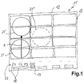
- FIG. 1 a top view of an induction hob with a large number of induction heating coils and two possible displacement paths of a pot.
- FIG. 1 A hob is shown in a plan view from above with a hob plate 12, under which a plurality of induction heating coils 15 are arranged in a heating area 13.
- a plurality of induction heating coils 15 are arranged in a heating area 13.
- heating devices are shown which essentially cover the area of the heating area 13.
- the induction heating coils 15 are advantageously made the same size, particularly advantageously identical.
- the hob 11 has a control device 17, advantageously by means of touch switches under the same hob plate 12.
- the control device has control elements 18, which can be formed, for example, by the mentioned touch switches, and at least one display 19.
- the display 19 is designed as a 7-segment display known per se. Here it shows a performance level "8".
- a pot 21 is set up in the front area on the left on the hob plate 12 or the heating area 13 and covers two induction heating coils 15 in such a way that they jointly serve to heat this pot 21.
- the setting up of the pot 21 may have been recognized by the induction heating coils themselves.
- further sensors can have detected it or an operator can enter the information on the operating device 17 by means of the operating elements 18 that the pot 21 is to be heated at the front left.
- a power level is selected by means of further control elements 18, namely power level “8”, which is then shown in the display 19.
- This power level 8 corresponds to a surface power density of about 5 W / cm 2 for the pot 21. It is therefore a large surface power density.
- the pot 21 is pushed backwards by the operator. This is intended to serve as a quick reaction to the fact that the water in the pot 21 threatens to boil over, which is not desired by the operator. Moving the pot 21 is then at least subjectively faster and more direct and more reliable for many operators than reducing the power by means of the operating device.
- the pot 21 with a reduced area power density can be used as a second new area power density operate.
- the power is reduced, namely at least to the limit value between small area power density and high area power density or a value between 3 W / cm 2 and 4 W / cm 2 , here 3.5 W / cm 2 . If the distance d were less than the minimum displacement, no action would take place.
- the specified first surface power density were set to be less than 3.5 W / cm 2 or less than 3 W / cm 2 or a power level of "7" or "6" or below, no change and in particular no reduction in the surface power density or . of the performance level in the new second position.
- the reduction of the power, otherwise the shifting and detection of the shifting of the pot, can be indicated optically and / or acoustically in a known manner.
- the option of a power takeover after the move can be offered to confirm or prevent or undo.
- an operator can effect that the surface power density or the power level is not permanently reduced by actuating a special control element, which is for example optically displayed.
- a special control element which is for example optically displayed.
- the area power density has been reduced at least temporarily immediately after the shift, it is then increased again to the original first area power density. If the operator lets more than the specified 10 seconds pass without valid actuation of the special operating element provided for this purpose, the reduced second area power density remains.
- This time of 10 seconds can generally also be varied and, for example, only be 3 seconds to 5 seconds or up to 20 seconds.
Landscapes
- Physics & Mathematics (AREA)
- Electromagnetism (AREA)
- Electric Stoves And Ranges (AREA)
Claims (14)
- Procédé pour faire fonctionner une table de cuisson (11) dotée de plusieurs dispositifs de chauffage (15), la table de cuisson présentant une plaque de cuisson (12) dotée d'une pluralité de dispositifs de chauffage (15) disposés au-dessous de celle-ci, comprenant les étapes consistant à :- poser un récipient de cuisson (21) sur la plaque de cuisson (12) dans une première position en recouvrant au moins un dispositif de chauffage (15),- faire fonctionner ledit au moins un dispositif de chauffage (15) avec une première densité de puissance surfacique prédéfinie déterminée pour chauffer le récipient de cuisson (21) ou son contenu,
caractérisé par l'étape consistant à- déplacer le récipient de cuisson (21) sur la plaque de cuisson (12) par un opérateur sur au moins un chemin de déplacement minimal déterminé vers une deuxième position, dans lequel, dans une étape avec différentiation de cas en fonction de la première densité de puissance surfacique prédéfinie déterminée pour ledit au moins un dispositif de chauffage (15) ou qui chauffe le récipient de cuisson (21'), une densité de puissance surfacique future est déterminée pour chauffer le récipient de cuisson dans la deuxième position,- dans lequel, dans un premier cas d'un chauffage précédent du récipient de cuisson (21) avec une petite densité de puissance surfacique, le récipient de cuisson (21') est aussi toujours chauffé dans la deuxième position avec la première densité de puissance surfacique précédente,- dans lequel, dans un deuxième cas d'un chauffage précédent du récipient de cuisson (21) avec une grande densité de puissance surfacique, la densité de puissance surfacique future qui chauffe le récipient de cuisson (21') dans la deuxième position est réduite. - Procédé selon la revendication 1, caractérisé en ce que les dispositifs de chauffage (15) sont adjacents et/ou recouvrent la majeure partie de la surface sous la plaque de cuisson dans un agencement régulier.
- Procédé selon la revendication 1 ou 2, caractérisé en ce que dans un deuxième cas d'un chauffage précédent du récipient de cuisson (21) avec une grande densité de puissance surfacique, la densité de puissance surfacique future est réduite au moins à une densité de puissance surfacique comprise entre 0,5 W/cm2 et 4 W/cm2 ou à une densité de puissance surfacique comprise entre une petite et une grande densité de puissance surfacique.
- Procédé selon la revendication 3, caractérisé en ce que la densité de puissance surfacique future est réduite encore plus qu'à une densité de puissance surfacique comprise entre 0,5 W/cm2 et 4 W/cm2 ou à une densité de puissance surfacique qui est comprise entre une petite et une grande densité de puissance surfacique.
- Procédé selon l'une quelconque des revendications précédentes, caractérisé en ce que la petite densité de puissance surfacique est inférieure à 3,5 W/cm2 et/ou la grande densité de puissance surfacique est supérieure à 3,5 W/cm2 ou supérieure à 45 % de la densité de puissance surfacique maximale.
- Procédé selon l'une quelconque des revendications précédentes, caractérisé en ce que, lorsqu'un déplacement du récipient de cuisson (21') a été constaté, un avertissement destiné à un opérateur est effectué, en particulier de manière optique et/ou acoustique.
- Procédé selon l'une quelconque des revendications précédentes, caractérisé en ce que, lorsqu'il a été constaté que le récipient de cuisson (21') se trouve dans la deuxième position sur la table de cuisson (11), pendant un délai de proposition déterminé, en particulier 1 s à 10 s, l'opérateur se voit proposer l'option de confirmer ou d'empêcher par une entrée de commande un transfert de puissance de la première densité de puissance surfacique précédente ou de la nouvelle deuxième densité de puissance surfacique.
- Procédé selon la revendication 7, caractérisé en ce qu'après expiration de ce délai de proposition, la densité de puissance surfacique est déterminée selon la différentiation de cas en premier cas ou en deuxième cas.
- Procédé selon l'une quelconque des revendications précédentes, caractérisé en ce que le chemin de déplacement minimal est supérieur à 5 cm, de préférence supérieur à 10 cm.
- Procédé selon l'une quelconque des revendications précédentes, caractérisé en ce que le chemin de déplacement minimal est supérieur à 50 % d'un diamètre du récipient de cuisson (21) posé, de préférence supérieur à 65 %.
- Procédé selon l'une quelconque des revendications précédentes, caractérisé en ce que le chemin de déplacement minimal est dimensionné de telle sorte qu'au moins un dispositif de chauffage (15) recouvert suffisamment pour un mode chauffage dans la première position, de préférence complètement recouvert, n'est plus recouvert dans sa deuxième position par le récipient de cuisson (21').
- Procédé selon l'une quelconque des revendications précédentes, caractérisé en ce qu'un chemin de déplacement minimal est dimensionné de telle sorte qu'un dispositif de chauffage (15) qui n'est pas suffisamment, de préférence pas du tout, recouvert pour un mode chauffage dans la première position est recouvert par le récipient de cuisson (21') dans la deuxième position à tel point qu'il fonctionne en mode chauffage.
- Procédé selon l'une quelconque des revendications précédentes, caractérisé en ce qu'une densité de puissance surfacique déterminée est prédéfinie par un opérateur par une entrée au niveau d'un dispositif de commande de la table de cuisson (11).
- Procédé selon l'une quelconque des revendications précédentes, caractérisé en ce que la table de cuisson (11) présente sous la plaque de cuisson (12) au moins deux fois quatre dispositifs de chauffage (15), en particulier trois fois quatre dispositifs de chauffage.
Priority Applications (1)
| Application Number | Priority Date | Filing Date | Title |
|---|---|---|---|
| PL17190630T PL3297397T3 (pl) | 2016-09-16 | 2017-09-12 | Sposób działania płyty kuchennej z kilkoma urządzeniami grzewczymi |
Applications Claiming Priority (1)
| Application Number | Priority Date | Filing Date | Title |
|---|---|---|---|
| DE102016217783.4A DE102016217783A1 (de) | 2016-09-16 | 2016-09-16 | Verfahren zum Betrieb eines Kochfeldes mit mehreren Heizeinrichtungen |
Publications (2)
| Publication Number | Publication Date |
|---|---|
| EP3297397A1 EP3297397A1 (fr) | 2018-03-21 |
| EP3297397B1 true EP3297397B1 (fr) | 2020-11-04 |
Family
ID=59858582
Family Applications (1)
| Application Number | Title | Priority Date | Filing Date |
|---|---|---|---|
| EP17190630.8A Active EP3297397B1 (fr) | 2016-09-16 | 2017-09-12 | Procédé de fonctionnement d'une plaque de cuisson dotée d'une pluralité de dispositifs de chauffage |
Country Status (4)
| Country | Link |
|---|---|
| EP (1) | EP3297397B1 (fr) |
| DE (1) | DE102016217783A1 (fr) |
| ES (1) | ES2845753T3 (fr) |
| PL (1) | PL3297397T3 (fr) |
Families Citing this family (4)
| Publication number | Priority date | Publication date | Assignee | Title |
|---|---|---|---|---|
| DE102018213655A1 (de) * | 2018-08-14 | 2020-02-20 | E.G.O. Elektro-Gerätebau GmbH | Verfahren zur Ansteuerung einer Heizeinrichtung eines Kochfelds und Kochfeld |
| DE102019219808A1 (de) | 2019-12-17 | 2021-06-17 | E.G.O. Elektro-Gerätebau GmbH | Verfahren zum Betrieb eines Kochgeräts und Kochgerät |
| KR20210083568A (ko) * | 2019-12-27 | 2021-07-07 | 엘지전자 주식회사 | 피가열체의 속성에 기초하여 화력이 조절되는 전기 레인지 |
| DE102020209648A1 (de) * | 2020-07-30 | 2022-02-03 | E.G.O. Elektro-Gerätebau GmbH | Verfahren zum Betrieb eines Kochfelds und Kochfeld |
Citations (10)
| Publication number | Priority date | Publication date | Assignee | Title |
|---|---|---|---|---|
| EP1610590A1 (fr) | 2004-06-25 | 2005-12-28 | Brandt Industries | Table de cuisson à plusieurs zones de cuisson |
| EP2211591A1 (fr) | 2009-01-22 | 2010-07-28 | BSH Bosch und Siemens Hausgeräte GmbH | Procédé de fonctionnement d'un champ de cuisson doté d'une multitude d'éléments de chauffage |
| DE102009020905A1 (de) | 2009-05-12 | 2010-12-09 | Diehl Ako Stiftung & Co. Kg | Kochfeld |
| DE102011102394A1 (de) | 2011-05-24 | 2012-11-29 | Diehl Ako Stiftung & Co. Kg | Vorrichtung und Verfahren zur Bedienung eines Kochfeldes |
| EP2800453A1 (fr) | 2013-04-30 | 2014-11-05 | Electrolux Appliances Aktiebolag | Table de cuisson et procédés pour faire fonctionner une telle plaque de cuisson |
| EP2833697A1 (fr) | 2013-07-31 | 2015-02-04 | BSH Bosch und Siemens Hausgeräte GmbH | Dispositif de plaque de cuisson |
| WO2015015361A1 (fr) | 2013-07-31 | 2015-02-05 | BSH Bosch und Siemens Hausgeräte GmbH | Système de table de cuisson |
| WO2015015360A1 (fr) | 2013-07-31 | 2015-02-05 | BSH Bosch und Siemens Hausgeräte GmbH | Système de table de cuisson |
| WO2015128759A1 (fr) | 2014-02-28 | 2015-09-03 | BSH Hausgeräte GmbH | Table de cuisson comprenant une multitude d'éléments chauffants |
| EP3001772A1 (fr) | 2014-09-24 | 2016-03-30 | BSH Hausgeräte GmbH | Plaque de cuisson |
Family Cites Families (2)
| Publication number | Priority date | Publication date | Assignee | Title |
|---|---|---|---|---|
| DE102013218715A1 (de) * | 2012-10-19 | 2014-04-24 | BSH Bosch und Siemens Hausgeräte GmbH | Kochfeldvorrichtung |
| DE102014224051A1 (de) | 2014-11-25 | 2016-05-25 | E.G.O. Elektro-Gerätebau GmbH | Induktionskochfeld und Verfahren zur Steuerung eines Induktionskochfelds |
-
2016
- 2016-09-16 DE DE102016217783.4A patent/DE102016217783A1/de active Pending
-
2017
- 2017-09-12 EP EP17190630.8A patent/EP3297397B1/fr active Active
- 2017-09-12 PL PL17190630T patent/PL3297397T3/pl unknown
- 2017-09-12 ES ES17190630T patent/ES2845753T3/es active Active
Patent Citations (10)
| Publication number | Priority date | Publication date | Assignee | Title |
|---|---|---|---|---|
| EP1610590A1 (fr) | 2004-06-25 | 2005-12-28 | Brandt Industries | Table de cuisson à plusieurs zones de cuisson |
| EP2211591A1 (fr) | 2009-01-22 | 2010-07-28 | BSH Bosch und Siemens Hausgeräte GmbH | Procédé de fonctionnement d'un champ de cuisson doté d'une multitude d'éléments de chauffage |
| DE102009020905A1 (de) | 2009-05-12 | 2010-12-09 | Diehl Ako Stiftung & Co. Kg | Kochfeld |
| DE102011102394A1 (de) | 2011-05-24 | 2012-11-29 | Diehl Ako Stiftung & Co. Kg | Vorrichtung und Verfahren zur Bedienung eines Kochfeldes |
| EP2800453A1 (fr) | 2013-04-30 | 2014-11-05 | Electrolux Appliances Aktiebolag | Table de cuisson et procédés pour faire fonctionner une telle plaque de cuisson |
| EP2833697A1 (fr) | 2013-07-31 | 2015-02-04 | BSH Bosch und Siemens Hausgeräte GmbH | Dispositif de plaque de cuisson |
| WO2015015361A1 (fr) | 2013-07-31 | 2015-02-05 | BSH Bosch und Siemens Hausgeräte GmbH | Système de table de cuisson |
| WO2015015360A1 (fr) | 2013-07-31 | 2015-02-05 | BSH Bosch und Siemens Hausgeräte GmbH | Système de table de cuisson |
| WO2015128759A1 (fr) | 2014-02-28 | 2015-09-03 | BSH Hausgeräte GmbH | Table de cuisson comprenant une multitude d'éléments chauffants |
| EP3001772A1 (fr) | 2014-09-24 | 2016-03-30 | BSH Hausgeräte GmbH | Plaque de cuisson |
Also Published As
| Publication number | Publication date |
|---|---|
| ES2845753T3 (es) | 2021-07-27 |
| EP3297397A1 (fr) | 2018-03-21 |
| DE102016217783A1 (de) | 2018-03-22 |
| PL3297397T3 (pl) | 2021-05-17 |
Similar Documents
| Publication | Publication Date | Title |
|---|---|---|
| EP3297397B1 (fr) | Procédé de fonctionnement d'une plaque de cuisson dotée d'une pluralité de dispositifs de chauffage | |
| EP1908333B1 (fr) | Procede de commande d un dispositif chauffant d'un appareil electrique chauffant a plusieurs dispositifs chauffants | |
| EP1580487A1 (fr) | Plaque de cuisson controlé de manière électronique avec plusieurs plaques électriques et procédé pour son opération | |
| EP2751490B1 (fr) | Appareil ménager à élément de commande et procédé de fonctionnement d'un appareil ménager | |
| EP3612002B1 (fr) | Procédé de commande d'un dispositif de chauffage d'un champ de cuisson et champ de cuisson | |
| EP1758431B1 (fr) | Plaque de cuisson commandée électroniquement comportant plusieurs feux et le procédé de commande de tels feux | |
| EP3330617B1 (fr) | Plaque de cuisson et procédé de fonctionnement d'une telle plaque de cuisson | |
| DE10211047A1 (de) | Anordnung zur Steuerung eines Kochfeldes | |
| DE20221600U1 (de) | Vorrichtung zum Steuern eines Gargerätes, insbesondere Haushaltsgargerätes | |
| EP3361827B1 (fr) | Procédé de fonctionnement d'une plaque de cuisson et plaque de cuisson | |
| EP3606285B1 (fr) | Procédé de commande de bobines de chauffage par induction d'une plaque de cuisson par induction | |
| DE102004016631A1 (de) | Vorrichtung und Verfahren zur Überwachung der Temperatur eines Kochgeschirrs auf einer Abdeckung eines Kochfeldes sowie von weiteren Vorgängen auf der Abdeckung | |
| EP3307019A1 (fr) | Procédé de fonctionnement d'un champ de cuisson à induction et champ de cuisson à induction | |
| DE102021214821B3 (de) | Verfahren zum Betrieb eines Kochfelds und Kochfeld | |
| EP3432684B1 (fr) | Procédé de fonctionnement d'une plaque de cuisson | |
| DE102005057083B4 (de) | Verfahren zum Zuschalten einer zweiten Kochstelle bei einem Kochfeld und Kochfeld | |
| EP3945749B1 (fr) | Procédé de fonctionnement d'une plaque de cuisson et plaque de cuisson | |
| DE102020200694B4 (de) | Verfahren zum Betrieb einer Kochfeldvorrichtung und Kochfeldvorrichtung | |
| DE2758465C2 (fr) | ||
| EP4306854A1 (fr) | Procédé de fonctionnement d'une plaque de cuisson et plaque de cuisson conçue à cet effet | |
| EP0982972B1 (fr) | Dispositif de commutation dans un chauffage électrique | |
| EP3330616B1 (fr) | Plaque de cuisson et procédé de fonctionnement d'une telle plaque de cuisson | |
| DE202010004437U1 (de) | Backofen zum Niedertemperaturgaren | |
| DE102004038826A1 (de) | Verfahren und Vorrichtung zur Steuerung eines Elektrogeräts mit mehreren elektrischen Verbrauchern | |
| DE102018204009B4 (de) | Verfahren zur Bedienung eines Elektrokochgeräts und Elektrokochgerät |
Legal Events
| Date | Code | Title | Description |
|---|---|---|---|
| PUAI | Public reference made under article 153(3) epc to a published international application that has entered the european phase |
Free format text: ORIGINAL CODE: 0009012 |
|
| STAA | Information on the status of an ep patent application or granted ep patent |
Free format text: STATUS: THE APPLICATION HAS BEEN PUBLISHED |
|
| AK | Designated contracting states |
Kind code of ref document: A1 Designated state(s): AL AT BE BG CH CY CZ DE DK EE ES FI FR GB GR HR HU IE IS IT LI LT LU LV MC MK MT NL NO PL PT RO RS SE SI SK SM TR |
|
| AX | Request for extension of the european patent |
Extension state: BA ME |
|
| STAA | Information on the status of an ep patent application or granted ep patent |
Free format text: STATUS: REQUEST FOR EXAMINATION WAS MADE |
|
| 17P | Request for examination filed |
Effective date: 20180919 |
|
| RBV | Designated contracting states (corrected) |
Designated state(s): AL AT BE BG CH CY CZ DE DK EE ES FI FR GB GR HR HU IE IS IT LI LT LU LV MC MK MT NL NO PL PT RO RS SE SI SK SM TR |
|
| GRAP | Despatch of communication of intention to grant a patent |
Free format text: ORIGINAL CODE: EPIDOSNIGR1 |
|
| STAA | Information on the status of an ep patent application or granted ep patent |
Free format text: STATUS: GRANT OF PATENT IS INTENDED |
|
| INTG | Intention to grant announced |
Effective date: 20200526 |
|
| GRAS | Grant fee paid |
Free format text: ORIGINAL CODE: EPIDOSNIGR3 |
|
| RAP1 | Party data changed (applicant data changed or rights of an application transferred) |
Owner name: E.G.O. ELEKTRO-GERAETEBAU GMBH |
|
| GRAA | (expected) grant |
Free format text: ORIGINAL CODE: 0009210 |
|
| STAA | Information on the status of an ep patent application or granted ep patent |
Free format text: STATUS: THE PATENT HAS BEEN GRANTED |
|
| AK | Designated contracting states |
Kind code of ref document: B1 Designated state(s): AL AT BE BG CH CY CZ DE DK EE ES FI FR GB GR HR HU IE IS IT LI LT LU LV MC MK MT NL NO PL PT RO RS SE SI SK SM TR |
|
| REG | Reference to a national code |
Ref country code: GB Ref legal event code: FG4D Free format text: NOT ENGLISH |
|
| REG | Reference to a national code |
Ref country code: CH Ref legal event code: EP |
|
| REG | Reference to a national code |
Ref country code: AT Ref legal event code: REF Ref document number: 1332511 Country of ref document: AT Kind code of ref document: T Effective date: 20201115 |
|
| REG | Reference to a national code |
Ref country code: DE Ref legal event code: R096 Ref document number: 502017008005 Country of ref document: DE |
|
| REG | Reference to a national code |
Ref country code: IE Ref legal event code: FG4D Free format text: LANGUAGE OF EP DOCUMENT: GERMAN |
|
| REG | Reference to a national code |
Ref country code: NL Ref legal event code: MP Effective date: 20201104 |
|
| PG25 | Lapsed in a contracting state [announced via postgrant information from national office to epo] |
Ref country code: FI Free format text: LAPSE BECAUSE OF FAILURE TO SUBMIT A TRANSLATION OF THE DESCRIPTION OR TO PAY THE FEE WITHIN THE PRESCRIBED TIME-LIMIT Effective date: 20201104 Ref country code: GR Free format text: LAPSE BECAUSE OF FAILURE TO SUBMIT A TRANSLATION OF THE DESCRIPTION OR TO PAY THE FEE WITHIN THE PRESCRIBED TIME-LIMIT Effective date: 20210205 Ref country code: PT Free format text: LAPSE BECAUSE OF FAILURE TO SUBMIT A TRANSLATION OF THE DESCRIPTION OR TO PAY THE FEE WITHIN THE PRESCRIBED TIME-LIMIT Effective date: 20210304 Ref country code: RS Free format text: LAPSE BECAUSE OF FAILURE TO SUBMIT A TRANSLATION OF THE DESCRIPTION OR TO PAY THE FEE WITHIN THE PRESCRIBED TIME-LIMIT Effective date: 20201104 Ref country code: NO Free format text: LAPSE BECAUSE OF FAILURE TO SUBMIT A TRANSLATION OF THE DESCRIPTION OR TO PAY THE FEE WITHIN THE PRESCRIBED TIME-LIMIT Effective date: 20210204 |
|
| PG25 | Lapsed in a contracting state [announced via postgrant information from national office to epo] |
Ref country code: SE Free format text: LAPSE BECAUSE OF FAILURE TO SUBMIT A TRANSLATION OF THE DESCRIPTION OR TO PAY THE FEE WITHIN THE PRESCRIBED TIME-LIMIT Effective date: 20201104 Ref country code: IS Free format text: LAPSE BECAUSE OF FAILURE TO SUBMIT A TRANSLATION OF THE DESCRIPTION OR TO PAY THE FEE WITHIN THE PRESCRIBED TIME-LIMIT Effective date: 20210304 Ref country code: LV Free format text: LAPSE BECAUSE OF FAILURE TO SUBMIT A TRANSLATION OF THE DESCRIPTION OR TO PAY THE FEE WITHIN THE PRESCRIBED TIME-LIMIT Effective date: 20201104 Ref country code: BG Free format text: LAPSE BECAUSE OF FAILURE TO SUBMIT A TRANSLATION OF THE DESCRIPTION OR TO PAY THE FEE WITHIN THE PRESCRIBED TIME-LIMIT Effective date: 20210204 |
|
| REG | Reference to a national code |
Ref country code: LT Ref legal event code: MG9D |
|
| PG25 | Lapsed in a contracting state [announced via postgrant information from national office to epo] |
Ref country code: HR Free format text: LAPSE BECAUSE OF FAILURE TO SUBMIT A TRANSLATION OF THE DESCRIPTION OR TO PAY THE FEE WITHIN THE PRESCRIBED TIME-LIMIT Effective date: 20201104 |
|
| REG | Reference to a national code |
Ref country code: ES Ref legal event code: FG2A Ref document number: 2845753 Country of ref document: ES Kind code of ref document: T3 Effective date: 20210727 |
|
| REG | Reference to a national code |
Ref country code: DE Ref legal event code: R026 Ref document number: 502017008005 Country of ref document: DE |
|
| PG25 | Lapsed in a contracting state [announced via postgrant information from national office to epo] |
Ref country code: SK Free format text: LAPSE BECAUSE OF FAILURE TO SUBMIT A TRANSLATION OF THE DESCRIPTION OR TO PAY THE FEE WITHIN THE PRESCRIBED TIME-LIMIT Effective date: 20201104 Ref country code: RO Free format text: LAPSE BECAUSE OF FAILURE TO SUBMIT A TRANSLATION OF THE DESCRIPTION OR TO PAY THE FEE WITHIN THE PRESCRIBED TIME-LIMIT Effective date: 20201104 Ref country code: CZ Free format text: LAPSE BECAUSE OF FAILURE TO SUBMIT A TRANSLATION OF THE DESCRIPTION OR TO PAY THE FEE WITHIN THE PRESCRIBED TIME-LIMIT Effective date: 20201104 Ref country code: EE Free format text: LAPSE BECAUSE OF FAILURE TO SUBMIT A TRANSLATION OF THE DESCRIPTION OR TO PAY THE FEE WITHIN THE PRESCRIBED TIME-LIMIT Effective date: 20201104 Ref country code: LT Free format text: LAPSE BECAUSE OF FAILURE TO SUBMIT A TRANSLATION OF THE DESCRIPTION OR TO PAY THE FEE WITHIN THE PRESCRIBED TIME-LIMIT Effective date: 20201104 Ref country code: SM Free format text: LAPSE BECAUSE OF FAILURE TO SUBMIT A TRANSLATION OF THE DESCRIPTION OR TO PAY THE FEE WITHIN THE PRESCRIBED TIME-LIMIT Effective date: 20201104 |
|
| PLBI | Opposition filed |
Free format text: ORIGINAL CODE: 0009260 |
|
| PLAX | Notice of opposition and request to file observation + time limit sent |
Free format text: ORIGINAL CODE: EPIDOSNOBS2 |
|
| PG25 | Lapsed in a contracting state [announced via postgrant information from national office to epo] |
Ref country code: DK Free format text: LAPSE BECAUSE OF FAILURE TO SUBMIT A TRANSLATION OF THE DESCRIPTION OR TO PAY THE FEE WITHIN THE PRESCRIBED TIME-LIMIT Effective date: 20201104 |
|
| 26 | Opposition filed |
Opponent name: BSH HAUSGERAETE GMBH Effective date: 20210728 |
|
| PG25 | Lapsed in a contracting state [announced via postgrant information from national office to epo] |
Ref country code: NL Free format text: LAPSE BECAUSE OF FAILURE TO SUBMIT A TRANSLATION OF THE DESCRIPTION OR TO PAY THE FEE WITHIN THE PRESCRIBED TIME-LIMIT Effective date: 20201104 Ref country code: AL Free format text: LAPSE BECAUSE OF FAILURE TO SUBMIT A TRANSLATION OF THE DESCRIPTION OR TO PAY THE FEE WITHIN THE PRESCRIBED TIME-LIMIT Effective date: 20201104 |
|
| PG25 | Lapsed in a contracting state [announced via postgrant information from national office to epo] |
Ref country code: SI Free format text: LAPSE BECAUSE OF FAILURE TO SUBMIT A TRANSLATION OF THE DESCRIPTION OR TO PAY THE FEE WITHIN THE PRESCRIBED TIME-LIMIT Effective date: 20201104 |
|
| PLBB | Reply of patent proprietor to notice(s) of opposition received |
Free format text: ORIGINAL CODE: EPIDOSNOBS3 |
|
| REG | Reference to a national code |
Ref country code: CH Ref legal event code: PL |
|
| REG | Reference to a national code |
Ref country code: BE Ref legal event code: MM Effective date: 20210930 |
|
| PG25 | Lapsed in a contracting state [announced via postgrant information from national office to epo] |
Ref country code: IS Free format text: LAPSE BECAUSE OF FAILURE TO SUBMIT A TRANSLATION OF THE DESCRIPTION OR TO PAY THE FEE WITHIN THE PRESCRIBED TIME-LIMIT Effective date: 20210304 Ref country code: MC Free format text: LAPSE BECAUSE OF FAILURE TO SUBMIT A TRANSLATION OF THE DESCRIPTION OR TO PAY THE FEE WITHIN THE PRESCRIBED TIME-LIMIT Effective date: 20201104 |
|
| PG25 | Lapsed in a contracting state [announced via postgrant information from national office to epo] |
Ref country code: LU Free format text: LAPSE BECAUSE OF NON-PAYMENT OF DUE FEES Effective date: 20210912 Ref country code: IE Free format text: LAPSE BECAUSE OF NON-PAYMENT OF DUE FEES Effective date: 20210912 Ref country code: BE Free format text: LAPSE BECAUSE OF NON-PAYMENT OF DUE FEES Effective date: 20210930 |
|
| PG25 | Lapsed in a contracting state [announced via postgrant information from national office to epo] |
Ref country code: LI Free format text: LAPSE BECAUSE OF NON-PAYMENT OF DUE FEES Effective date: 20210930 Ref country code: CH Free format text: LAPSE BECAUSE OF NON-PAYMENT OF DUE FEES Effective date: 20210930 |
|
| PLCK | Communication despatched that opposition was rejected |
Free format text: ORIGINAL CODE: EPIDOSNREJ1 |
|
| APBM | Appeal reference recorded |
Free format text: ORIGINAL CODE: EPIDOSNREFNO |
|
| APBP | Date of receipt of notice of appeal recorded |
Free format text: ORIGINAL CODE: EPIDOSNNOA2O |
|
| APAH | Appeal reference modified |
Free format text: ORIGINAL CODE: EPIDOSCREFNO |
|
| PG25 | Lapsed in a contracting state [announced via postgrant information from national office to epo] |
Ref country code: HU Free format text: LAPSE BECAUSE OF FAILURE TO SUBMIT A TRANSLATION OF THE DESCRIPTION OR TO PAY THE FEE WITHIN THE PRESCRIBED TIME-LIMIT; INVALID AB INITIO Effective date: 20170912 |
|
| PG25 | Lapsed in a contracting state [announced via postgrant information from national office to epo] |
Ref country code: CY Free format text: LAPSE BECAUSE OF FAILURE TO SUBMIT A TRANSLATION OF THE DESCRIPTION OR TO PAY THE FEE WITHIN THE PRESCRIBED TIME-LIMIT Effective date: 20201104 |
|
| APBQ | Date of receipt of statement of grounds of appeal recorded |
Free format text: ORIGINAL CODE: EPIDOSNNOA3O |
|
| PGFP | Annual fee paid to national office [announced via postgrant information from national office to epo] |
Ref country code: GB Payment date: 20230921 Year of fee payment: 7 |
|
| REG | Reference to a national code |
Ref country code: AT Ref legal event code: MM01 Ref document number: 1332511 Country of ref document: AT Kind code of ref document: T Effective date: 20220912 |
|
| PGFP | Annual fee paid to national office [announced via postgrant information from national office to epo] |
Ref country code: PL Payment date: 20230811 Year of fee payment: 7 Ref country code: FR Payment date: 20230918 Year of fee payment: 7 Ref country code: DE Payment date: 20230921 Year of fee payment: 7 |
|
| PGFP | Annual fee paid to national office [announced via postgrant information from national office to epo] |
Ref country code: ES Payment date: 20231019 Year of fee payment: 7 |
|
| PG25 | Lapsed in a contracting state [announced via postgrant information from national office to epo] |
Ref country code: AT Free format text: LAPSE BECAUSE OF NON-PAYMENT OF DUE FEES Effective date: 20220912 |
|
| PGFP | Annual fee paid to national office [announced via postgrant information from national office to epo] |
Ref country code: IT Payment date: 20230929 Year of fee payment: 7 |
|
| PG25 | Lapsed in a contracting state [announced via postgrant information from national office to epo] |
Ref country code: MK Free format text: LAPSE BECAUSE OF FAILURE TO SUBMIT A TRANSLATION OF THE DESCRIPTION OR TO PAY THE FEE WITHIN THE PRESCRIBED TIME-LIMIT Effective date: 20201104 |