EP3297053A1 - Gaserzeugerzelle mit aussenliegender widerstandsfolie - Google Patents
Gaserzeugerzelle mit aussenliegender widerstandsfolie Download PDFInfo
- Publication number
- EP3297053A1 EP3297053A1 EP16189534.7A EP16189534A EP3297053A1 EP 3297053 A1 EP3297053 A1 EP 3297053A1 EP 16189534 A EP16189534 A EP 16189534A EP 3297053 A1 EP3297053 A1 EP 3297053A1
- Authority
- EP
- European Patent Office
- Prior art keywords
- cell
- resistance foil
- resistance
- cathode
- foil
- Prior art date
- Legal status (The legal status is an assumption and is not a legal conclusion. Google has not performed a legal analysis and makes no representation as to the accuracy of the status listed.)
- Granted
Links
Images
Classifications
-
- C—CHEMISTRY; METALLURGY
- C25—ELECTROLYTIC OR ELECTROPHORETIC PROCESSES; APPARATUS THEREFOR
- C25B—ELECTROLYTIC OR ELECTROPHORETIC PROCESSES FOR THE PRODUCTION OF COMPOUNDS OR NON-METALS; APPARATUS THEREFOR
- C25B9/00—Cells or assemblies of cells; Constructional parts of cells; Assemblies of constructional parts, e.g. electrode-diaphragm assemblies; Process-related cell features
- C25B9/17—Cells comprising dimensionally-stable non-movable electrodes; Assemblies of constructional parts thereof
- C25B9/19—Cells comprising dimensionally-stable non-movable electrodes; Assemblies of constructional parts thereof with diaphragms
-
- C—CHEMISTRY; METALLURGY
- C25—ELECTROLYTIC OR ELECTROPHORETIC PROCESSES; APPARATUS THEREFOR
- C25B—ELECTROLYTIC OR ELECTROPHORETIC PROCESSES FOR THE PRODUCTION OF COMPOUNDS OR NON-METALS; APPARATUS THEREFOR
- C25B15/00—Operating or servicing cells
- C25B15/04—Regulation of the inter-electrode distance
-
- C—CHEMISTRY; METALLURGY
- C25—ELECTROLYTIC OR ELECTROPHORETIC PROCESSES; APPARATUS THEREFOR
- C25B—ELECTROLYTIC OR ELECTROPHORETIC PROCESSES FOR THE PRODUCTION OF COMPOUNDS OR NON-METALS; APPARATUS THEREFOR
- C25B1/00—Electrolytic production of inorganic compounds or non-metals
- C25B1/01—Products
- C25B1/02—Hydrogen or oxygen
- C25B1/04—Hydrogen or oxygen by electrolysis of water
-
- C—CHEMISTRY; METALLURGY
- C25—ELECTROLYTIC OR ELECTROPHORETIC PROCESSES; APPARATUS THEREFOR
- C25B—ELECTROLYTIC OR ELECTROPHORETIC PROCESSES FOR THE PRODUCTION OF COMPOUNDS OR NON-METALS; APPARATUS THEREFOR
- C25B15/00—Operating or servicing cells
- C25B15/02—Process control or regulation
-
- C—CHEMISTRY; METALLURGY
- C25—ELECTROLYTIC OR ELECTROPHORETIC PROCESSES; APPARATUS THEREFOR
- C25B—ELECTROLYTIC OR ELECTROPHORETIC PROCESSES FOR THE PRODUCTION OF COMPOUNDS OR NON-METALS; APPARATUS THEREFOR
- C25B9/00—Cells or assemblies of cells; Constructional parts of cells; Assemblies of constructional parts, e.g. electrode-diaphragm assemblies; Process-related cell features
- C25B9/01—Electrolytic cells characterised by shape or form
- C25B9/015—Cylindrical cells
-
- C—CHEMISTRY; METALLURGY
- C25—ELECTROLYTIC OR ELECTROPHORETIC PROCESSES; APPARATUS THEREFOR
- C25B—ELECTROLYTIC OR ELECTROPHORETIC PROCESSES FOR THE PRODUCTION OF COMPOUNDS OR NON-METALS; APPARATUS THEREFOR
- C25B9/00—Cells or assemblies of cells; Constructional parts of cells; Assemblies of constructional parts, e.g. electrode-diaphragm assemblies; Process-related cell features
- C25B9/60—Constructional parts of cells
- C25B9/65—Means for supplying current; Electrode connections; Electric inter-cell connections
-
- C—CHEMISTRY; METALLURGY
- C25—ELECTROLYTIC OR ELECTROPHORETIC PROCESSES; APPARATUS THEREFOR
- C25B—ELECTROLYTIC OR ELECTROPHORETIC PROCESSES FOR THE PRODUCTION OF COMPOUNDS OR NON-METALS; APPARATUS THEREFOR
- C25B9/00—Cells or assemblies of cells; Constructional parts of cells; Assemblies of constructional parts, e.g. electrode-diaphragm assemblies; Process-related cell features
- C25B9/70—Assemblies comprising two or more cells
- C25B9/73—Assemblies comprising two or more cells of the filter-press type
-
- Y—GENERAL TAGGING OF NEW TECHNOLOGICAL DEVELOPMENTS; GENERAL TAGGING OF CROSS-SECTIONAL TECHNOLOGIES SPANNING OVER SEVERAL SECTIONS OF THE IPC; TECHNICAL SUBJECTS COVERED BY FORMER USPC CROSS-REFERENCE ART COLLECTIONS [XRACs] AND DIGESTS
- Y02—TECHNOLOGIES OR APPLICATIONS FOR MITIGATION OR ADAPTATION AGAINST CLIMATE CHANGE
- Y02E—REDUCTION OF GREENHOUSE GAS [GHG] EMISSIONS, RELATED TO ENERGY GENERATION, TRANSMISSION OR DISTRIBUTION
- Y02E60/00—Enabling technologies; Technologies with a potential or indirect contribution to GHG emissions mitigation
- Y02E60/30—Hydrogen technology
- Y02E60/36—Hydrogen production from non-carbon containing sources, e.g. by water electrolysis
Definitions
- the present invention relates to an electrochemical cell for generating hydrogen, which will also be referred to below as a hydrogen evolution cell.
- Electrochemical cells for the production of hydrogen are known in various designs. In particular, such cells are often constructed as button cells. An exemplary structure of such cells is in DE 3532335 A1 described.
- the production of hydrogen is based on cells such as those in the DE 3532335 A1 described on an electrochemical reaction.
- a current flows through a cell which comprises as anode an metal such as zinc, ie an electrochemically oxidizable substance, and as cathode a catalyst electrode capable of decomposing water, hydrogen is formed.
- electrolyte such cell types contain an aqueous alkaline electrolyte.
- the known hydrogen evolution cells always comprise a housing which has at least one opening as a gas outlet opening, through which generated hydrogen can escape from the interior of the housing.
- the breakthrough is imperative for the operation of the cells, with prolonged storage substances such as carbon dioxide or atmospheric oxygen can penetrate into the housing interior and lead there to undesirable chemical reactions.
- the at least one opening is usually covered with a removable sticker in the form of a label with a small grip tab.
- Such protected cells are for example in Fig. 1 of the EP 1325876 B1 shown.
- this removable label must be removed in many applications. Namely, hydrogen generated in the cell should be able to escape from the inside of the case as easily as possible. This is not only useful for the proper operation of the cells but may even be necessary for safety reasons.
- known hydrogen evolution cells can form in an unintentional blockage of the gas outlet opening pressures that are large enough to burst the cells.
- the present invention has for its object to provide a technical solution for the provision of hydrogen, which allows to adjust the hydrogen evolution rate in existing devices such as the aforementioned fragrance dispensers without having to be adapted or exchanged for a built-in devices load resistance.
- the cell according to the invention serves to generate hydrogen. It has an anode comprising an electrochemically oxidisable substance (for example zinc or magnesium or an alloy of these metals) and a hydrogen generating electrode as the cathode (for example one of the electrodes shown in US Pat DE 3532335 A1 described catalyst electrodes).
- the catalyst electrodes are in this case preferably designed as gas diffusion electrodes with a thin active layer, in which a suitable catalyst is embedded.
- DE 3532335 A1 is hereby incorporated by reference.
- the electrochemical cell preferably contains an aqueous alkaline electrolyte, for example potassium hydroxide solution.
- an aqueous alkaline electrolyte for example potassium hydroxide solution.
- hydrogen evolution is voluntary when the anode is electrically connected to the cathode.
- the anode and the cathode are formed such that the hydrogen production begins at the cathode as soon as the anode and the cathode are electrically connected to each other.
- the cell according to the invention further comprises a housing which encloses an inner space in which the anode and the cathode are arranged separated from one another by a separator.
- This housing has an opening through which hydrogen generated at the electrode for generating hydrogen can escape from the interior.
- the cell of the invention is characterized in that at least one outer side of the housing at least one resistor foil is adhered, which, when it is connected as a load resistor between the anode and the cathode, the current flow between the anode and the cathode and thus also the gas generation rate decreases.
- the resistance foil is preferably selected so that the gas generation rate is lowered by at least 1% and by a maximum of 99%, particularly preferably by at least 10% and by a maximum of 90%.
- the resistance foil of a cell according to the invention particularly preferably has a sheet resistance in the range from 1 m ⁇ / ⁇ to 100 k ⁇ / ⁇ , preferably in the range from 1 m ⁇ / ⁇ to 50 k ⁇ / ⁇ , particularly preferably in the range from 5 m ⁇ / ⁇ to 50 k ⁇ / ⁇ , in particular in the range of 5 m ⁇ / ⁇ to 100 ⁇ / ⁇ .
- the metal layer is preferably made of copper, of aluminum, of nickel, of cobalt, of precious metals such as gold, silver and platinum or of an alloy of one of these metals.
- the resistance layer is based for example on a polymer with a defined electrical conductivity, a resistance alloy or a carbon-based material.
- the adhesive layer is preferably formed from an acrylate adhesive or an epoxy adhesive.
- adhesive layers are used which themselves have a limited electrical conductivity and which can take over the function of a resistive layer.
- electrically conductive particles or polymer constituents are silver particles, nickel particles, cobalt particles, brass particles or bronze particles.
- a resistance foil with the sequence adhesive layer / metal layer / adhesive layer can, if both adhesive layers are formed conductive, stick on at least one outer side of the housing of a cell according to the invention.
- a further layer of adhesive is then available to bond the cell, for example, to an electrical contact or an electronic component.
- the resistance foil preferably has a thickness in the range from 40 ⁇ m to 2000 ⁇ m. Within this range, a range of 50 microns to 500 microns, in particular from 50 microns to 250 microns, more preferred.
- An adhesive layer within the composite generally has a thickness of between 10 .mu.m and 100 .mu.m.
- the cell according to the invention is designed as a button cell and comprises a cylindrical housing whose outer side comprises a flat upper side, a flat lower side and a circumferential lateral surface.
- the housing preferably consists of a cell cup, a cell lid and a seal, wherein the cell lid is inserted into the cell cup and the seal separates the cell cup and the cell lid from each other. In this state, the bottom of the cell cup forms the flat bottom of the case while the bottom of the cell lid forms the flat top of the case.
- the at least one aperture is introduced into the bottom of the cell cup or the cell lid. It is particularly preferably introduced into the bottom of the cell cup.
- a cell designed as a button cell according to the present invention comprises at least one resistance foil, more preferably exactly one resistance foil, which is glued onto the flat upper side of its housing.
- a cell formed as a button cell according to the present invention comprises at least one resistance foil, more preferably exactly one resistance foil, which is glued to the flat underside of its housing.
- a cell formed as a button cell according to the present invention comprises at least one resistance foil, more preferably exactly one resistance foil, which is adhesively bonded to the circumferential surface of its housing.
- the cell according to the invention is effectively protected against the ingress of substances such as carbon dioxide or atmospheric oxygen before it is put into operation.
- the resistance foil therefore serves to improve the storage stability.
- the at least one predetermined crack site and the at least one passage in the form of the hole or slot also ensure that hydrogen formed in the cell can escape from the interior without it being necessary to remove the resistance foil from the outside of the housing.
- a pressure inside the cell it leads in the presence of the resistance foil with the at least one predetermined crack point to a tearing of the resistance foil along at least one Sollrissstelle.
- hydrogen formed in the cell can escape through this passage from the cell.
- the pressure generated in the cell interior initially leads to a slight lifting of the resistance foil until hydrogen from the cell interior has made its way through the opening to the at least one passage.
- the resistance foil covers the bottom of the cell cup or the cell lid completely or almost completely.
- predetermined crack point In the context of the present invention, this is to be understood as meaning a point at which the resistance foil of a cell according to the invention preferably tears when the resistance foil is exposed to pressure due to hydrogen escaping from the cell.
- the setpoint crack is realized by targeted weakening of the resistance foil at this point. See more below.
- the housing of a cell according to the invention has more than one opening. If this is the case, it is preferred according to the present invention that each of the openings is covered with the resistance foil having the at least one predetermined crack location and / or the at least one passage in the form of a hole or a slot.
- the cell has 2 to 4 openings.
- the aperture (s) are typically simple holes that have been inserted into the housing by a drilling or punching operation or by a laser. They may have both a round and an angular shape, this is not critical in the context of the present invention.
- the aperture (s) preferably have a minimum diameter of not less than 0.1 mm, more preferably not less than 0.5 mm, preferably not less than 1.0 mm. It is further preferred that the openings / openings have a diameter of not more than 1.5 mm.
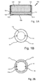
- Fig. 1A schematically shows the cross section of a preferred embodiment of an electrochemical cell 100 according to the invention.
- the preferred embodiment is a button cell. Shown are the cell cup 101 and the inserted therein cell cover 102, from which the housing of the button cell is formed.
- the housing has a cylindrical shape. On the front side, the housing is delimited by the bottoms of the cell cup 101 and the cell lid 102, on the shell side by the wall of the cell cup 101.
- the hydrogen-generating catalyst electrode 104 is contained in the cell 100 in the form of a flat layer.
- the flat separator 105 rests directly on the catalyst electrode 104. It separates the catalyst electrode 104 from the anode 106. This contains as a electrochemically oxidizable substance, a metal powder, namely zinc.
- the openings 107a and 107b are incorporated.
- the bottom of the cell cup 101 (corresponding to the flat underside of the housing) is taped to the film 108. This completely covers the openings 107a and 107b and thus protects the interior of the cell 100 from penetration of, for example, carbon dioxide.
- the foil 108 is a resistance foil consisting of a copper layer and an adhesive layer.
- the copper layer has a thickness of approximately 35 ⁇ m.
- the adhesive layer has a thickness of about 30 microns. It is made from an acrylate-based adhesive and has electrical conductivity.
- the sheet resistance of the resistance foil is 5 m ⁇ / ⁇ /.
- Fig. 1B schematically shows a plan view of the bottom of the cell cup 101 of FIG Fig. 1A
- the film 108 has the perforated line 112 as a predetermined crack point.
- hydrogen is generated inside the housing.
- the film 108 tears at at least one of the predetermined crack locations 108a and 108b. Thereafter, the generated hydrogen can escape from the cell unhindered.
- FIG. 1C illustrates a top view of the bottom of a cell cup 101 of a cell that is exactly identical to the one in FIG Fig. 1 shown cell, except for the film 108.
- a film 111 is shown, which has the passageways 108a and 108b in the form of arcuately arranged slots instead of a predetermined tear point.
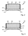
- FIG. 2 illustrated embodiment of an inventive electrochemical cell 200 is substantially identical to the in Fig. 1 represented cell. Shown are the cell cup 201, the cell lid 202 inserted therein, the plastic gasket 203, the catalyst electrode 204, the sheet separator 205, the anode 206, the apertures 207a and 207b, and a resistive foil 208. All of these cell components do not differ from the corresponding components of FIG Cell 100.
- the cell 208 is on the flat top of the cell housing (corresponding to the bottom of the cell lid 202).
- FIG. 3 illustrated embodiment of an inventive electrochemical cell 300 is also substantially identical to the in Fig. 1 represented cell. Shown are the cell cup 301, the cell lid 302 inserted therein, the plastic gasket 303, the catalyst electrode 304, the sheet separator 305, the anode 306, the openings 307a and 307b, and a resistance foil 308. All of these cell components do not differ from the corresponding components of the cell 100th
Landscapes
- Chemical & Material Sciences (AREA)
- Engineering & Computer Science (AREA)
- Chemical Kinetics & Catalysis (AREA)
- Electrochemistry (AREA)
- Materials Engineering (AREA)
- Metallurgy (AREA)
- Organic Chemistry (AREA)
- Automation & Control Theory (AREA)
- Inorganic Chemistry (AREA)
- Electrolytic Production Of Non-Metals, Compounds, Apparatuses Therefor (AREA)
- Sealing Battery Cases Or Jackets (AREA)
Abstract
Description
- Die vorliegende Erfindung betrifft eine elektrochemische Zelle zur Erzeugung von Wasserstoff, die im Folgenden auch kurz als Wasserstoffentwicklungszelle bezeichnet wird.
- Elektrochemische Zellen zur Erzeugung von Wasserstoff sind in diversen Bauformen bekannt. Insbesondere werden solche Zellen häufig als Knopfzellen konstruiert. Ein beispielhafter Aufbau solcher Zellen ist in der
DE 3532335 A1 beschrieben. - Die Erzeugung von Wasserstoff basiert bei Zellen wie den in der
DE 3532335 A1 beschriebenen auf einer elektrochemischen Reaktion. Beim Durchfluss eines Stroms durch eine Zelle, die als Anode ein Metall wie Zink, also eine elektrochemisch oxidierbare Substanz, und als Kathode eine zur Zersetzung von Wasser befähigte Katalysatorelektrode umfasst, kommt es zur Bildung von Wasserstoff. Als Elektrolyt enthalten solche Zelltypen einen wässrigen alkalischen Elektrolyten. - Die bekannten Wasserstoffentwicklungszellen umfassen stets ein Gehäuse, das als Gasaustrittsöffnung mindestens eine Durchbrechung aufweist, durch welche erzeugter Wasserstoff aus dem Inneren des Gehäuses entweichen kann. Die Durchbrechung ist für den Betrieb der Zellen zwingend erforderlich, bei längerer Lagerung können Stoffe wie Kohlendioxid oder Luftsauerstoff ins Gehäuseinnere eindringen und dort zu unerwünschten chemischen Reaktionen führen. Aus diesem Grund ist die mindestens eine Durchbrechung in aller Regel mit einem ablösbaren Aufkleber in Form eines Etiketts mit einer kleinen Grifflasche abgedeckt. Derlei geschützte Zellen sind beispielsweise in
Fig. 1 derEP 1325876 B1 dargestellt. Vor Inbetriebnahme der Zellen muss dieser ablösbare Aufkleber bei vielen Anwendungen allerdings entfernt werden. In der Zelle erzeugter Wasserstoff soll nämlich möglichst problemlos aus dem Gehäuseinneren austreten können. Dies ist nicht nur für den ordnungsgemäßen Betrieb der Zellen zweckmäßig sondern kann aus Sicherheitsgründen sogar erforderlich sein. Bei den aus derDE 3532335 A1 bekannten Wasserstoffentwicklungszellen können sich bei einer unbeabsichtigten Blockade der Gasausaustrittsöffnung Drücke bilden, die groß genug sind, um die Zellen platzen zu lassen. - Es gibt zahlreiche Anwendungen für Wasserstoffentwicklungszellen wie die in der
DE 3532335 A1 beschriebenen. Sehr häufig werden sie im Zusammenhang mit dem Austrag von fließfähigen Medien eingesetzt. So kann der erzeugte Wasserstoff z.B. den Kolben eines Fettspenders antreiben, wie das in derDE 3532335 A1 beschrieben ist. Aus derEP 2674623 A1 ist die Verwendung von Wasserstoff erzeugenden Zellen zum Austrag von Desinfektionsmitteln und von Duftstoffen aus Duftspendern bekannt. - Bei Wasserstoffentwicklungszellen wie den in der
DE 3532335 A1 beschriebenen Zellen mit Zinkanode läuft die Wasserstoffentwicklung in der Regel freiwillig ab, wenn die Anode elektrisch mit der Kathode verbunden wird. Zur Einstellung der Wasserstoffentwicklungsrate wird ein Lastwiderstand zwischen die Anode und die Kathode geschaltet. Dieser Lastwiderstand ist in der Regel immer ein Teil einer größeren Vorrichtung wie z.B. den genannten Duftspendern. Die Wasserstoffentwicklungszelle wird in diese eingesetzt. Im Betrieb kommt es dann zu einer im Wesentlichen konstanten Wasserstoffentwicklung. Eine nachträgliche Anpassung der Wasserstoffentwicklungsrate ist nur sehr aufwendig möglich. Es bedarf hierzu eines Austauschs oder einer Anpassung des Lastwiderstands. - Der vorliegenden Erfindung lag die Aufgabe zugrunde, eine technische Lösung zur Bereitstellung von Wasserstoff bereitzustellen, die es erlaubt, die Wasserstoffentwicklungsrate in bestehenden Vorrichtungen wie den genannten Duftspendern nachträglich anzupassen, ohne dass hierfür ein in die Vorrichtungen integrierter Lastwiderstand angepasst oder ausgetauscht werden muss.
- Diese Aufgabe wird gelöst durch die elektrochemische Zelle mit den Merkmalen des Anspruchs 1. Bevorzugte Ausführungsformen der erfindungsgemäßen Zelle sind in den abhängigen Ansprüche 2 bis 9 angegeben. Der Wortlaut sämtlicher Ansprüche wird hiermit zum Inhalt der vorliegenden Beschreibung gemacht.
- Die erfindungsgemäße Zelle dient zur Erzeugung von Wasserstoff. Sie weist sie eine Anode umfassend eine elektrochemisch oxidierbare Substanz (beispielsweise Zink oder Magnesium oder eine Legierung dieser Metalle) und eine zur Wasserstoff-Erzeugung ausgebildete Elektrode als Kathode (beispielsweise eine der in der
DE 3532335 A1 beschriebenen Katalysatorelektroden) auf. Die Katalysatorelektroden sind hierbei bevorzugt als Gasdiffusionselektroden ausgebildet mit einer dünnen Aktivschicht, in die ein geeigneter Katalysator eingebettet ist. Auf den diesbezüglichen Inhalt derDE 3532335 A1 wird hiermit Bezug genommen. - Als Elektrolyt enthält die elektrochemische Zelle bevorzugt einen wässrigen alkalischen Elektrolyten, beispielsweise Kalilauge.
- Bei der erfindungsgemäßen Zelle läuft die Wasserstoffentwicklung freiwillig ab, wenn die Anode elektrisch mit der Kathode verbunden wird. Zu diesem Zweck sind die Anode und die Kathode derart ausgebildet, dass die Wasserstofferzeugung an der Kathode einsetzt, sobald die Anode und die Kathode elektrisch miteinander verbunden werden.
- Die erfindungsgemäße Zelle umfasst weiterhin ein Gehäuse, das einen Innenraum umschließt, in dem die Anode und die Kathode - voneinander getrennt durch einen Separator - angeordnet sind. Dieses Gehäuse weist eine Durchbrechung auf, durch welche an der zur Wasserstoff-Erzeugung ausgebildeten Elektrode erzeugter Wasserstoff aus dem Innenraum entweichen kann.
- Besonders zeichnet sich die erfindungsgemäße Zelle dadurch aus, dass auf mindestens eine Außenseite des Gehäuses mindestens eine Widerstandsfolie aufgeklebt ist, die, wenn sie als Lastwiderstand zwischen die Anode und die Kathode geschaltet wird, den Stromfluss zwischen der Anode und der Kathode und damit auch die Gaserzeugungsrate herabsetzt.
- Dies erlaubt es, die Wasserstoffentwicklungsrate in Vorrichtungen wie den eingangs genannten Duftspendern nachträglich anzupassen, ohne dass hierfür ein in die Vorrichtungen integrierter Lastwiderstand angepasst oder ausgetauscht werden muss. Stattdessen ist es lediglich erforderlich, die Wasserstoffentwicklungszelle in diesen Vorrichtungen durch eine erfindungsgemäße Zelle zu ersetzen, wobei die Widerstandsfolie so platziert sein sollte, dass sie bei einem Betrieb der Zelle in Serie zu einem der integrierten Lastwiderstände geschaltet ist. Mittels der mindestens einen Widerstandsfolie kann die Gaserzeugungsrate auf einen gewünschten Wert herabgesetzt werden.
- Die Widerstandsfolie wird bevorzugt so gewählt, dass die Gaserzeugungsrate um mindestens 1 % und um maximal 99 %, besonders bevorzugt um mindestens 10 % und um maximal 90 %, abgesenkt wird.
- Besonders bevorzugt weist die Widerstandsfolie einer erfindungsgemäßen Zelle einen Flächenwiderstand im Bereich von 1 mΩ/□ bis 100 kΩ/□, bevorzugt im Bereich von 1 mΩ/□ bis 50 kΩ/□, besonders bevorzugt im Bereich von 5 mΩ/□ bis 50 kΩ/□, insbesondere im Bereich von 5 mΩ/□ bis 100 Ω/□.
- Im Rahmen der Erfindung einsetzbare Widerstandsfolien umfassen in bevorzugten Ausführungsformen mindestens eine der folgenden Komponenten:
- mindestens eine Metallschicht,
- mindestens eine Widerstandsschicht und
- mindestens eine Klebstoffschicht.
- In besonders bevorzugten Ausführungsformen weist die Widerstandsfolie eine der folgenden Schichtabfolgen auf:
- Metallschicht / Klebstoffschicht
- Klebstoffschicht / Metallschicht / Klebstoffschicht
- Metallschicht / Widerstandsschicht / Metallschicht
- Klebstoffschicht / Metallschicht / Widerstandsschicht / Metallschicht
- Klebstoffschicht / Metallschicht / Widerstandsschicht / Metallschicht / Klebstoffschicht
- Die Metallschicht besteht bevorzugt aus Kupfer, aus Aluminium, aus Nickel, aus Kobalt, aus Edelmetallen wie Gold, Silber und Platin oder aus einer Legierung eines dieser Metalle.
- Die Widerstandsschicht basiert beispielsweise auf einem Polymer mit definierter elektrischer Leitfähigkeit, einer Widerstandslegierung oder einem kohlenstoffbasierten Material.
- Die Klebstoffschicht ist bevorzugt aus einem Acrylatkleber oder aus einem Epoxidkleber gebildet.
- In einigen besonders bevorzugten Ausführungsformen werden Klebstoffschichten verwendet, die selbst eine begrenzte elektrische Leitfähigkeit aufweisen und die die Funktion einer Widerstandsschicht übernehmen können. Zur Herstellung solcher Klebstoffschichten können einem Klebstoff beispielsweise elektrisch leitende Partikel oder Polymerbestandteile zugesetzt werden. Geeignet sind beispielsweise Silberpartikel, Nickelpartikel, Kobaltpartikel, Messingpartikel oder Bronzepartikel.
- Eine Widerstandsfolie mit der Sequenz Klebstoffschicht / Metallschicht / Klebstoffschicht lässt sich, wenn beide Klebstoffschichten leitfähig ausgebildet sind, auf mindestens eine Außenseite des Gehäuses einer erfindungsgemäßen Zelle aufkleben. Eine weitere Klebstoffschicht steht dann zur Verfügung, um die Zelle beispielsweise mit einem elektrischen Kontakt oder einem elektronischen Bauelement zu verkleben.
- Bevorzugt weist die Widerstandsfolie - einschließlich aller ihrer Schichten - eine Dicke im Bereich von 40 µm bis 2000 µm auf. Innerhalb dieses Bereiches ist ein Bereich von 50 µm bis 500 µm, insbesondere von 50 µm bis 250 µm, weiter bevorzugt. Eine Klebstoffschicht innerhalb des Verbundes weist dabei in der Regel eine Dicke zwischen 10 µm und 100 µm auf.
- In einer besonders bevorzugten Ausführungsformen ist die erfindungsgemäße Zelle als Knopfzelle ausgebildet und umfasst ein zylindrisches Gehäuse, dessen Außenseite eine flache Oberseite, eine flache Unterseite und eine umlaufende Mantelfläche umfasst. Dabei besteht das Gehäuse bevorzugt aus einem Zellenbecher, einem Zellendeckel und einer Dichtung, wobei der Zellendeckel in den Zellenbecher eingeschoben ist und die Dichtung den Zellenbecher und den Zellendeckel voneinander trennt. In diesem Zustand bildet der Boden des Zellenbechers die flache Unterseite des Gehäuses während der Boden des Zellendeckels die flache Oberseite des Gehäuses bildet.
- Es ist bevorzugt, dass die mindestens eine Durchbrechung in den Boden des Zellenbechers oder des Zellendeckels eingebracht ist. Besonders bevorzugt ist sie in den Boden des Zellenbechers eingebracht.
- In einer möglichen Weiterbildung umfasst eine als Knopfzelle ausgebildete Zelle gemäß der vorliegenden Erfindung mindestens eine Widerstandsfolie, besonders bevorzugt genau eine Widerstandsfolie, die auf die flache Oberseite ihres Gehäuses aufgeklebt ist.
- In einer weiteren möglichen Weiterbildung umfasst eine als Knopfzelle ausgebildete Zelle gemäß der vorliegenden Erfindung mindestens eine Widerstandsfolie, besonders bevorzugt genau eine Widerstandsfolie, die auf die flache Unterseite ihres Gehäuses aufgeklebt ist.
- In einer dritten möglichen Weiterbildung umfasst eine als Knopfzelle ausgebildete Zelle gemäß der vorliegenden Erfindung mindestens eine Widerstandsfolie, besonders bevorzugt genau eine Widerstandsfolie, die auf die umlaufende Mantelfläche ihres Gehäuses aufgeklebt ist.
- In einer bevorzugten Ausführungsform der erfindungsgemäßen Zelle ist die mindestens eine Durchbrechung im Boden des Zellenbechers mittels der Widerstandsfolie auf der flachen Unterseite des Gehäuses verschlossen. Die Widerstandsfolie deckt dabei die mindestens eine Durchbrechung sowie einen die mindestens eine Durchbrechung umgebenden Bereich der Unterseite ab. Die Widerstandsfolie dient in dieser Ausführungsform also dem gleichen Zweck wie der bereits erwähnte, aus dem Stand der Technik bekannte ablösbare Aufkleber in Form eines Etiketts. Im Unterschied zu diesen Etiketten weist die Widerstandsfolie in bevorzugten Ausführungsformen allerdings
- mindestens eine Sollrissstelle auf, die bei der ersten Inbetriebnahme der Zelle durch einen in Folge der einsetzenden Wasserstofferzeugung im Innenraum sich bildenden Druck aufreißt
- sie weist in dem die Durchbrechung umgebenden Bereich mindestens einen Durchlass in Gestalt eines Loches oder eines Schlitzes auf.
- Diese beiden Merkmale bewirken grundsätzlich den gleichen technischen Effekt, sie können daher alternativ zueinander oder aber in Kombination miteinander eingesetzt werden. Sowohl durch eine Widerstandsfolie mit der mindestens einen Sollrissstelle als auch durch eine Widerstandsfolie mit dem mindestens einen Durchlass in Gestalt des Loches oder Schlitzes in dem die Durchbrechung umgebenden Bereich wird die erfindungsgemäße Zelle wirksam vor ihrer Inbetriebnahme vor dem Eindringen von Stoffen wie Kohlendioxid oder Luftsauerstoff geschützt. Die Widerstandsfolie dient daher der Verbesserung der Lagerstabilität. Gleichzeitig gewährleisten die mindestens eine Sollrissstelle und der mindestens eine Durchlass in Gestalt des Loches oder Schlitzes aber auch, dass in der Zelle gebildeter Wasserstoff aus dem Innenraum entweichen kann, ohne dass es zuvor erforderlich ist, die Widerstandsfolie von der Außenseite des Gehäuses abzuziehen.
- Bildet sich bei der Inbetriebnahme der Zelle ein Druck im Inneren der Zelle, so führt dieser bei Anwesenheit der Widerstandsfolie mit der mindestens einen Sollrissstelle zu einem Aufreißen der Widerstandsfolie entlang mindestens einer Sollrissstelle. Bei Anwesenheit der Widerstandsfolie mit dem mindestens einen Durchlass kann in der Zelle gebildeter Wasserstoff durch diesen Durchlass aus der Zelle entweichen. In der Regel führt der im Zellinneren entstehende Druck zunächst zu einem leichten Anheben der Widerstandsfolie bis sich Wasserstoff aus dem Zellinneren seinen Weg durch die Durchbrechung hin zu dem mindestens einen Durchlass gebahnt hat. Es ist nämlich in aller Regel bevorzugt, dass die Durchbrechung und der mindestens eine Durchlass nicht überlappen. Eine Überlappung hätte negative Auswirkungen auf die Lagerstabilität der erfindungsgemäßen Zelle. Aus diesem Grund ist der mindestens eine Durchlass in Gestalt eines Loches oder eines Schlitzes auch in dem die Durchbrechung umgebenden Bereich angeordnet.
- Besonders bevorzugt deckt die Widerstandsfolie den Boden des Zellenbechers oder des Zellendeckels vollständig oder nahezu vollständig ab.
- Zum Begriff "Sollrissstelle": Im Rahmen der vorliegenden Erfindung soll hierunter eine Stelle verstanden werden, an der die Widerstandsfolie einer erfindungsgemäßen Zelle bevorzugt reißt, wenn die Widerstandsfolie einem Druck durch aus der Zelle entweichenden Wasserstoff ausgesetzt wird. Realisiert wird die Sollrissstelle durch gezielte Materialschwächung der Widerstandsfolie an dieser Stelle. Hierzu unten noch mehr.
- In bevorzugten Ausführungsformen weist das Gehäuse einer erfindungsgemäßen Zelle mehr als eine Durchbrechung auf. Sofern dies der Fall ist, so ist es gemäß der vorliegenden Erfindung bevorzugt, dass jede der Durchbrechungen mit der Widerstandsfolie mit der mindestens eine Sollrissstelle und/oder dem mindestens einen Durchlass in Gestalt eines Loches oder eines Schlitzes abgedeckt ist.
- Besonders bevorzugt weist die Zelle 2 bis 4 Durchbrechungen auf.
- Bei der Durchbrechung / den Durchbrechungen handelt es sich in der Regel um einfache Löcher, die durch einen Bohr- oder einen Stanzvorgang oder mittels eines Lasers ins Gehäuse eingebracht wurden. Sie können sowohl eine runde als auch eine eckige Form haben, dies ist im Rahmen der vorliegenden Erfindung unkritisch.
- Die Durchbrechung / Durchbrechungen weisen bevorzugt einen minimalen Durchmesser von nicht weniger als 0,1 mm, besonders bevorzugt von nicht weniger als 0,5 mm, vorzugsweise von nicht weniger als 1,0 mm, auf. Es ist weiterhin bevorzugt, dass die Durchbrechung / Durchbrechungen einen Durchmesser von nicht mehr als 1,5 mm, aufweisen.
- Wie oben bereits ausgeführt, wird die Sollrissstelle bevorzugt durch gezielte Materialschwächung der Widerstandsfolie realisiert. In bevorzugten Ausführungsformen ist die erfindungsgemäße Zelle weiterhin durch mindestens eines der folgenden Merkmale gekennzeichnet:
- In einer bevorzugten Ausführungsform ist die mindestens eine Sollrissstelle als punkt- oder linienförmige Schwächung der Widerstandsfolie realisiert.
- In einer bevorzugten Ausführungsform ist die Schwächung herbeigeführt durch Perforation entlang einer Schwächungslinie. Unter Perforation entlang einer Schwächungslinie ist hierbei die linienförmige Schwächung mittels Durchlochung der Widerstandsfolie in vorzugsweise regelmäßigen Abständen zu verstehen.
- In einer bevorzugten Ausführungsform kann die Schwächung auch kontinuierlich und frei von Löchern entlang einer Schwächungslinie ausgeführt sein. Alternativ zur Perforation kann eine gezielte Materialschwächung entlang einer Schwächungslinie auch durch eine alternative Vorgehensweise, beispielsweise mittels eines Prägevorgangs entlang einer Linie oder durch gezielte Materialschwächung mittels thermischer oder chemischer Behandlung, beispielsweise mittels eines Lasers oder eines Ätzprozesses, herbeigeführt werden.
- In einer bevorzugten Ausführungsform ist die Sollrissstelle als linienförmige Schwächung der Widerstandsfolie mit bogen- oder kreisförmiger Geometrie realisiert.
- In einer bevorzugten Ausführungsform ist die Sollrissstelle als linienförmige Schwächung der Widerstandsfolie entlang einer oder mehrerer Geraden realisiert.
- Wenn die Widerstandsfolie in dem die Durchbrechung umgebenden Bereich den mindestens einen Durchlass in Gestalt eines Loches oder eines Schlitzes aufweist, so ist Folgendes bevorzugt:
- Der mindestens eine Durchlass umfasst mehrere Löcher und/oder Schlitze entlang einer Linie.
- Die Linie ist entlang einer oder mehrerer Geraden oder mit bogen- oder kreisförmiger Geometrie realisiert.
- Weitere Merkmale der Erfindung sowie aus der Erfindung resultierende Vorteile ergeben sich aus den Zeichnungen sowie aus der nachfolgenden Beschreibung der Zeichnungen. Die nachfolgend beschriebenen Ausführungsformen dienen lediglich zur Erläuterung und zum besseren Verständnis der Erfindung und sind in keiner Weise einschränkend zu verstehen.
-
Fig. 1A zeigt schematisch den Querschnitt einer bevorzugten Ausführungsform einer erfindungsgemäßen elektrochemischen Zelle 100. - Bei der bevorzugten Ausführungsform handelt es sich um eine Knopfzelle. Dargestellt sind der Zellenbecher 101 und der darin eingeschobene Zellendeckel 102, aus denen das Gehäuse der Knopfzelle gebildet ist. Das Gehäuse weist eine zylindrische Form auf. Stirnseitig wird das Gehäuse durch die Böden des Zellenbechers 101 und des Zellendeckels 102 begrenzt, mantelseitig durch die Wand des Zellenbechers 101.
- Zwischen dem Zellenbecher 101 und dem Zellendeckel 102 ist die Kunststoffdichtung 103 angeordnet, die den Zellenbecher 101 und den Zellendeckel 102 räumlich und elektrisch voneinander trennt. Die zur Wasserstofferzeugung ausgebildete Katalysatorelektrode 104 ist in der Zelle 100 in Form einer flachen Schicht enthalten. Der flächige Separator 105 liegt unmittelbar auf der Katalysatorelektrode 104 auf. Er trennt die Katalysatorelektrode 104 von der Anode 106. Diese enthält als elektrochemisch oxidierbare Substanz ein Metallpulver, nämlich Zink.
- In den Boden des Zellbechers 101 sind die Durchbrechungen 107a und 107b eingearbeitet. Der Boden des Zellenbechers 101 (entsprechend der flachen Unterseite des Gehäuses) ist mit der Folie 108 abgeklebt. Diese deckt die Durchbrechungen 107a und 107b vollständig ab und schützt somit das Innere der Zelle 100 vor einem Eindringen etwa von Kohlendioxid.
- Bei der Folie 108 handelt es sich um eine Widerstandsfolie bestehend aus einer Kupferschicht und einer Klebstoffschicht. Die Kupferschicht weist eine Dicke von ca. 35 µm auf. Die Klebstoffschicht weist eine Dicke von ca. 30 µm auf. Sie wurde aus einem Klebstoff auf Acrylatbasis gebildet und weist eine elektrische Leitfähigkeit auf. Der Flächenwiderstand der Widerstandsfolie beträgt 5 mΩ/□/.
- Wenn die Widerstandsfolie 108 als Lastwiderstand zwischen die Anode 106 und die Kathode 104 geschaltet wird, so setzt dies den Stromfluss zwischen der Anode 106 und der Kathode 104 und damit auch die Gaserzeugungsrate herab.
-
Fig. 1B zeigt schematisch eine Draufsicht auf den Boden des Zellenbechers 101 der inFig. 1A dargestellten bevorzugten Ausführungsform einer erfindungsgemäßen elektrochemischen Zelle 100. Hier ist zu erkennen, dass die Folie 108 als Sollrissstelle die perforierte Linie 112 aufweist. Wird die Zelle 100 in Betrieb genommen und lässt man einen Strom durch sie fließen, so wird im Inneren des Gehäuses Wasserstoff gebildet. Durch den in der Folge ansteigenden Druck zerreißt die Folie 108 an mindestens einer der Sollrissstellen 108a und 108b. Danach kann der erzeugte Wasserstoff ungehindert aus der Zelle austreten. - Hervorgehoben sind die punktförmigen Bereiche 113 und 114 der Folie 108. In diesen Bereichen überlappt die Folie 108 mit den Durchbrechungen 107a und 107b.
- Fig. 1C illustriert eine Draufsicht auf den Boden eines Zellenbechers 101 einer Zelle, die exakt baugleich zur in
Fig. 1 dargestellten Zelle ist, abgesehen von der Folie 108. An Stelle der Folie 108 ist hier eine Folie 111 dargestellt, die an Stelle einer Sollrissstelle die Durchlässe 108a und 108b jeweils in Form von bogenförmig angeordneten Schlitzen aufweist. - Hervorgehoben sind die punktförmigen Bereiche 113 und 114 der Folie 111. In diesen Bereichen überlappt die Folie 111 mit den Durchbrechungen 107a und 107b.
- Die in
Fig. 2 dargestellte Ausführungsform einer erfindungsgemäßen elektrochemischen Zelle 200 ist im Wesentlichen baugleich zu der inFig. 1 dargestellten Zelle. Dargestellt sind der Zellenbecher 201, der darin eingeschobene Zellendeckel 202, die Kunststoffdichtung 203, die Katalysatorelektrode 204, der flächige Separator 205, die Anode 206, die Durchbrechungen 207a und 207b und eine Widerstandsfolie 208. Alle diese Zellkomponenten unterscheiden sich nicht von den entsprechenden Komponenten der Zelle 100. - Unterschiede betreffen lediglich die Platzierung der Widerstandsfolie 208. An Stelle der Folie 108 auf dem Boden des Zellenbechers 101 weist die in
Fig. 2 dargestellte Zelle die Folie 208 auf der flachen Oberseite des Zellgehäuses (entsprechend dem Boden des Zellendeckels 202) auf. - Die in
Fig. 3 dargestellte Ausführungsform einer erfindungsgemäßen elektrochemischen Zelle 300 ist ebenfalls im Wesentlichen baugleich zu der inFig. 1 dargestellten Zelle. Dargestellt sind der Zellenbecher301, der darin eingeschobene Zellendeckel 302, die Kunststoffdichtung 303, die Katalysatorelektrode 304, der flächige Separator 305, die Anode 306, die Durchbrechungen 307a und 307b und eine Widerstandsfolie 308. Alle diese Zellkomponenten unterscheiden sich nicht von den entsprechenden Komponenten der Zelle 100. - Unterschiede betreffen lediglich die Platzierung der Widerstandsfolie 308. An Stelle der Folie 108 auf dem Boden des Zellenbechers 101 weist die in
Fig. 2 dargestellte Zelle die Folie 308 auf der umlaufende Mantelfläche des Gehäuses der Knopfzelle auf.
Claims (9)
- Elektrochemische Zelle zur Erzeugung von Wasserstoff, mit den Merkmalen(a) die Zelle weist eine Anode umfassend eine elektrochemisch oxidierbare Substanz sowie eine zur Wasserstoff-Erzeugung ausgebildete Elektrode als Kathode sowie einen wässrigen alkalischen Elektrolyten auf,(b) die Anode und die Kathode sind derart ausgebildet, dass die Wasserstofferzeugung an der Kathode einsetzt, sobald die Anode und die Kathode elektrisch miteinander verbunden werden,(c) die Zelle umfasst ein Gehäuse, das einen Innenraum umschließt, in dem die Anode und die Kathode - voneinander getrennt durch einen Separator - angeordnet sind, und(d) das Gehäuse weist mindestens eine Durchbrechung auf, durch welche an der zur Wasserstoff-Erzeugung ausgebildeten Elektrode erzeugter Wasserstoff aus dem Innenraum entweichen kann,sowie dem zusätzlichen Merkmal(e) auf mindestens eine Außenseite des Gehäuses ist mindestens eine Widerstandsfolie aufgeklebt, die, wenn sie als Lastwiderstand zwischen die Anode und die Kathode geschaltet wird, den Stromfluss zwischen der Anode und der Kathode und damit auch die Gaserzeugungsrate herabsetzt.
- Zelle nach Anspruch 1 mit mindestens dem folgenden zusätzlichen Merkmal:(a) Die Widerstandsfolie weist einen Flächenwiderstand im Bereich von 1 mΩ/□ bis 100 kΩ/□ auf.
- Zelle nach Anspruch 1 oder Anspruch 2 mit mindestens einem der folgenden zusätzlichen Merkmale:(a) Die Widerstandsfolie umfasst mindestens eine Metallschicht.(b) Die Widerstandsfolie umfasst mindestens eine Widerstandsschicht.(c) Die Widerstandsfolie umfasst mindestens eine Klebstoffschicht.(d) Die Widerstandsfolie weist die folgende Schichtabfolge auf: Metallschicht / Klebstoffschicht.(e) Die Widerstandsfolie weist die folgende Schichtabfolge auf: Klebstoffschicht / Metallschicht / Klebstoffschicht.(f) Die Widerstandsfolie weist die folgende Schichtabfolge auf: Metallschicht / Widerstandsschicht / Metallschicht.(g) Die Widerstandsfolie weist die folgende Schichtabfolge auf: Klebstoffschicht / Metallschicht / Widerstandsschicht / Metallschicht.(h) Die Widerstandsfolie weist die folgende Schichtabfolge auf: Klebstoffschicht / Metallschicht / Widerstandsschicht / Metallschicht / Klebstoffschicht.
- Zelle nach Anspruch 3 mit mindestens einem der folgenden zusätzlichen Merkmale:(a) Die Metallschicht besteht aus Kupfer, aus Aluminium, aus Nickel, aus Kobalt, aus Edelmetallen wie Gold, Silber und Platin oder einer Legierung eines dieser Metalle.(b) Die Widerstandsschicht basiert auf einem Polymer mit definierter Leitfähigkeit, einer Widerstandslegierung oder einem kohlenstoffbasierten Material.(c) Die Klebstoffschicht ist bevorzugt aus einem Acrylatkleber oder aus einem Epoxidkleber gebildet.
- Zelle nach einem der vorhergehenden Ansprüche mit mindestens einem der folgenden zusätzlichen Merkmale:(a) Die Zelle ist als Knopfzelle ausgebildet und umfasst ein zylindrisches Gehäuse, dessen Außenseite eine flache Oberseite, eine flache Unterseite und eine umlaufende Mantelfläche umfasst.(b) Das Gehäuse besteht aus einem Zellenbecher, einem Zellendeckel und einer Dichtung, wobei der Zellendeckel in den Zellenbecher eingeschoben ist und die Dichtung den Zellenbecher und den Zellendeckel voneinandertrennt.(c) Die mindestens eine Durchbrechung ist in den Boden des Zellenbechers oder des Zellendeckels eingebracht.
- Zelle nach Anspruch 5 mit mindestens einem der folgenden zusätzlichen Merkmale:(a) Die Zelle ist eine Knopfzelle und sie umfasst mindestens eine Widerstandsfolie, die auf die flache Oberseite ihres Gehäuses aufgeklebt ist.(b) Die Zelle ist eine Knopfzelle und sie umfasst mindestens eine Widerstandsfolie, die auf die flache Unterseite ihres Gehäuses aufgeklebt ist.(c) Die Zelle ist eine Knopfzelle und sie umfasst mindestens eine Widerstandsfolie, die auf die umlaufende Mantelfläche ihres Gehäuses der Knopfzelle aufgeklebt ist.
- Zelle nach Anspruch 6 mit mindestens einem der folgenden zusätzlichen Merkmale:(a) Die mindestens eine Durchbrechung im Boden des Zellenbechers ist mittels der Widerstandsfolie auf der flachen Unterseite des Gehäuses verschlossen.(b) Die Widerstandsfolie deckt die mindestens eine Durchbrechung sowie einen die mindestens eine Durchbrechung umgebenden Bereich ab.(c) Die Widerstandsfolie weist mindestens eine Sollrissstelle auf, die bei der ersten Inbetriebnahme der Zelle durch einen in Folge der einsetzenden Wasserstoff- oder Sauerstoff-Erzeugung im Innenraum sich bildenden Druck aufreißt.(d) Die Widerstandsfolie weist in dem die Durchbrechung umgebenden Bereich mindestens einen Durchlass in Gestalt eines Loches oder eines Schlitzes auf.
- Zelle nach Anspruch 7 mit mindestens einem der folgenden zusätzlichen Merkmale:(a) Die mindestens eine Sollrissstelle ist als punkt- oder linienförmige Schwächung der Widerstandsfolie realisiert.(b) Die Schwächung ist herbeigeführt durch Perforation entlang einer Schwächungslinie.(c) Die Schwächung ist kontinuierlich und frei von Löchern entlang einer Schwächungslinie ausgeführt.(d) Die Sollrissstelle ist als linienförmige Schwächung der Widerstandsfolie mit bogen- oder kreisförmiger Geometrie realisiert.(e) Die Sollrissstelle ist als linienförmige Schwächung der Widerstandsfolie entlang einer oder mehrerer Geraden realisiert.
- Zelle nach Anspruch 7 mit mindestens einem der folgenden zusätzlichen Merkmale:(a) Der mindestens eine Durchlass umfasst mehrere Löcher und/oder Schlitze entlang einer Linie.(b) Die Linie ist entlang einer oder mehrerer Geraden oder mit bogen- oder kreisförmiger Geometrie realisiert.
Priority Applications (2)
| Application Number | Priority Date | Filing Date | Title |
|---|---|---|---|
| EP16189534.7A EP3297053B1 (de) | 2016-09-19 | 2016-09-19 | Gaserzeugerzelle mit aussenliegender widerstandsfolie |
| US15/708,666 US10392716B2 (en) | 2016-09-19 | 2017-09-19 | Electrochemical cell that generates hydrogen |
Applications Claiming Priority (1)
| Application Number | Priority Date | Filing Date | Title |
|---|---|---|---|
| EP16189534.7A EP3297053B1 (de) | 2016-09-19 | 2016-09-19 | Gaserzeugerzelle mit aussenliegender widerstandsfolie |
Publications (2)
| Publication Number | Publication Date |
|---|---|
| EP3297053A1 true EP3297053A1 (de) | 2018-03-21 |
| EP3297053B1 EP3297053B1 (de) | 2018-11-07 |
Family
ID=56943442
Family Applications (1)
| Application Number | Title | Priority Date | Filing Date |
|---|---|---|---|
| EP16189534.7A Active EP3297053B1 (de) | 2016-09-19 | 2016-09-19 | Gaserzeugerzelle mit aussenliegender widerstandsfolie |
Country Status (2)
| Country | Link |
|---|---|
| US (1) | US10392716B2 (de) |
| EP (1) | EP3297053B1 (de) |
Cited By (2)
| Publication number | Priority date | Publication date | Assignee | Title |
|---|---|---|---|---|
| CN110129825A (zh) * | 2019-05-23 | 2019-08-16 | 天津市大陆制氢设备有限公司 | 一种高效Ni/Ni(OH)2析氢电极及其制备方法 |
| AT527258A1 (de) * | 2023-05-17 | 2024-12-15 | Andritz Ag Maschf | Elektrolysezelle und Elektrolysevorrichtung mit einer Elektrolysezelle |
Citations (6)
| Publication number | Priority date | Publication date | Assignee | Title |
|---|---|---|---|---|
| DE3532335A1 (de) | 1985-09-11 | 1987-03-12 | Winsel August | Galvanische zelle zur entwicklung von wasserstoff bzw. sauerstoff |
| US5486429A (en) * | 1995-04-24 | 1996-01-23 | Aer Energy Resources, Inc. | Diffusion vent for a rechargeable metal-air cell |
| EP1325876B1 (de) | 2001-12-19 | 2005-02-09 | VARTA Microbattery GmbH | Verkaufs- und Vorratspackung für Zink/Luftzellen |
| US20130143104A1 (en) * | 2007-04-13 | 2013-06-06 | Varta Microbattery Gmbh | Button cell comprising a coated exterior |
| EP2674623A1 (de) | 2012-06-11 | 2013-12-18 | VARTA Microbattery GmbH | Verfahren und Vorrichtung zum dosierten Austrag eines Mediums |
| US20140056327A1 (en) * | 2011-02-25 | 2014-02-27 | Varta Microbattery Gmbh | Status indicator for temperature-sensitive goods |
Family Cites Families (11)
| Publication number | Priority date | Publication date | Assignee | Title |
|---|---|---|---|---|
| US3614670A (en) * | 1969-11-05 | 1971-10-19 | Richard G Wilson | Switchable microwave circulator wherein ground planes are comprised of foils having vertically conductive particles |
| DE2535269C3 (de) * | 1975-08-07 | 1979-01-04 | Varta Batterie Ag, 3000 Hannover | Galvanisches Primärelement mit alkalischem Elektrolyten und einer hydrophoben Luftelektrode |
| US5242565A (en) * | 1989-07-10 | 1993-09-07 | August Winsel | Device for electrochemical generation of gases for the transportation of fluids and similar mediums |
| US5393617A (en) * | 1993-10-08 | 1995-02-28 | Electro Energy, Inc. | Bipolar electrochmeical battery of stacked wafer cells |
| MY120789A (en) * | 1998-01-16 | 2005-11-30 | Toyo Kohan Co Ltd | Closed battery and closing member |
| US6468692B1 (en) * | 1999-06-08 | 2002-10-22 | Ngk Insulators, Ltd. | Lithium secondary battery with sealed casing members |
| US6503658B1 (en) * | 2001-07-11 | 2003-01-07 | Electro Energy, Inc. | Bipolar electrochemical battery of stacked wafer cells |
| US7833647B2 (en) * | 2004-04-28 | 2010-11-16 | Eveready Battery Company, Inc. | Closure vent seal and assembly |
| WO2006049989A1 (en) * | 2004-10-29 | 2006-05-11 | Eveready Battery Company, Inc. | Fluid regulating microvalve assembly for fluid consuming cells |
| WO2009015129A1 (en) * | 2007-07-24 | 2009-01-29 | Rovcal, Inc. | On-demand hydrogen gas generation device |
| US9859531B2 (en) * | 2015-02-06 | 2018-01-02 | Ovonic Battery Company, Inc. | Alkaline and non-aqueous proton-conducting pouch-cell batteries |
-
2016
- 2016-09-19 EP EP16189534.7A patent/EP3297053B1/de active Active
-
2017
- 2017-09-19 US US15/708,666 patent/US10392716B2/en active Active
Patent Citations (6)
| Publication number | Priority date | Publication date | Assignee | Title |
|---|---|---|---|---|
| DE3532335A1 (de) | 1985-09-11 | 1987-03-12 | Winsel August | Galvanische zelle zur entwicklung von wasserstoff bzw. sauerstoff |
| US5486429A (en) * | 1995-04-24 | 1996-01-23 | Aer Energy Resources, Inc. | Diffusion vent for a rechargeable metal-air cell |
| EP1325876B1 (de) | 2001-12-19 | 2005-02-09 | VARTA Microbattery GmbH | Verkaufs- und Vorratspackung für Zink/Luftzellen |
| US20130143104A1 (en) * | 2007-04-13 | 2013-06-06 | Varta Microbattery Gmbh | Button cell comprising a coated exterior |
| US20140056327A1 (en) * | 2011-02-25 | 2014-02-27 | Varta Microbattery Gmbh | Status indicator for temperature-sensitive goods |
| EP2674623A1 (de) | 2012-06-11 | 2013-12-18 | VARTA Microbattery GmbH | Verfahren und Vorrichtung zum dosierten Austrag eines Mediums |
Cited By (3)
| Publication number | Priority date | Publication date | Assignee | Title |
|---|---|---|---|---|
| CN110129825A (zh) * | 2019-05-23 | 2019-08-16 | 天津市大陆制氢设备有限公司 | 一种高效Ni/Ni(OH)2析氢电极及其制备方法 |
| AT527258A1 (de) * | 2023-05-17 | 2024-12-15 | Andritz Ag Maschf | Elektrolysezelle und Elektrolysevorrichtung mit einer Elektrolysezelle |
| AT527258B1 (de) * | 2023-05-17 | 2025-07-15 | Andritz Ag Maschf | Elektrolysezelle und Elektrolysevorrichtung mit einer Elektrolysezelle |
Also Published As
| Publication number | Publication date |
|---|---|
| EP3297053B1 (de) | 2018-11-07 |
| US10392716B2 (en) | 2019-08-27 |
| US20180080132A1 (en) | 2018-03-22 |
Similar Documents
| Publication | Publication Date | Title |
|---|---|---|
| DE19630336B4 (de) | Sicherheitsvorrichtung für eine gekapselte Zelle | |
| DE102012016816B4 (de) | Gassensor | |
| DE3532335C2 (de) | ||
| DE102009048236A1 (de) | Elektrochemische Zelle | |
| DE2848017A1 (de) | Trockenzellenbatterie | |
| EP2851972B1 (de) | Lithium-Ionen-Akkumulator mit verringerter Gefährdung durch Abblasen | |
| DE2843577A1 (de) | Selbstentlueftende batterie | |
| DE2814667A1 (de) | Alkalische primaer-zelle | |
| DE102014117410B4 (de) | Elektrisches Kontaktelement, Einpressstift, Buchse und Leadframe | |
| DE102020129734A1 (de) | Batteriezelle, Gehäuse einer solchen Batteriezelle und Verfahren zu dessen Herstellung | |
| EP3297053B1 (de) | Gaserzeugerzelle mit aussenliegender widerstandsfolie | |
| DE2710760C2 (de) | ||
| WO2019228722A1 (de) | Hybride batteriekomponente und verfahren zum herstellen einer hybriden batteriekomponente | |
| DE2631684A1 (de) | Verfahren und vorrichtung zur gewinnung von zink aus einer alkalischen zinkatloesung | |
| EP3477727B1 (de) | Energiespeichervorrichtung und herstellungsverfahren | |
| EP3297062B1 (de) | Elektrochemische zelle zur erzeugung von wasserstoff oder sauerstoff | |
| DE60013137T2 (de) | Elektrochemische zelle mit niedrigprofil-entlüftungsdichtungsatz | |
| DE202020105202U1 (de) | Knopfbatterie | |
| EP2643868B1 (de) | Gehäuse für quecksilberfreie knopfzellen | |
| EP3131155B1 (de) | Wiederaufladbare energiespeichereinheit | |
| EP1500159B1 (de) | Schmelzkarbonatbrennstoffzelle und verfahren zur herstellung einer solchen | |
| DE2531350A1 (de) | Implantables elektromedizinisches geraet | |
| DE19823463C2 (de) | Vorrichtung zum Abdichten einer Deckplatte und deren Verwendung für eine Elektrolysezelle | |
| WO2014198450A1 (de) | Lagerstabile gaserzeugungszelle | |
| DE1596146B1 (de) | Galvanisches lagerelement bei welchem eine elektrode durch eine isolierschicht vom elektrolyten getrennt ist die bei der aktivierung durch mechanische kraefte zerstoert wird |
Legal Events
| Date | Code | Title | Description |
|---|---|---|---|
| PUAI | Public reference made under article 153(3) epc to a published international application that has entered the european phase |
Free format text: ORIGINAL CODE: 0009012 |
|
| STAA | Information on the status of an ep patent application or granted ep patent |
Free format text: STATUS: THE APPLICATION HAS BEEN PUBLISHED |
|
| AK | Designated contracting states |
Kind code of ref document: A1 Designated state(s): AL AT BE BG CH CY CZ DE DK EE ES FI FR GB GR HR HU IE IS IT LI LT LU LV MC MK MT NL NO PL PT RO RS SE SI SK SM TR |
|
| AX | Request for extension of the european patent |
Extension state: BA ME |
|
| STAA | Information on the status of an ep patent application or granted ep patent |
Free format text: STATUS: REQUEST FOR EXAMINATION WAS MADE |
|
| 17P | Request for examination filed |
Effective date: 20180430 |
|
| RBV | Designated contracting states (corrected) |
Designated state(s): AL AT BE BG CH CY CZ DE DK EE ES FI FR GB GR HR HU IE IS IT LI LT LU LV MC MK MT NL NO PL PT RO RS SE SI SK SM TR |
|
| GRAP | Despatch of communication of intention to grant a patent |
Free format text: ORIGINAL CODE: EPIDOSNIGR1 |
|
| STAA | Information on the status of an ep patent application or granted ep patent |
Free format text: STATUS: GRANT OF PATENT IS INTENDED |
|
| RIC1 | Information provided on ipc code assigned before grant |
Ipc: H01M 12/06 20060101ALI20180703BHEP Ipc: H01M 4/04 20060101ALI20180703BHEP Ipc: C25B 15/02 20060101ALI20180703BHEP Ipc: C25B 9/04 20060101ALI20180703BHEP Ipc: H01M 2/12 20060101ALI20180703BHEP Ipc: H01M 4/42 20060101ALN20180703BHEP Ipc: C25B 1/04 20060101ALI20180703BHEP Ipc: C25B 9/08 20060101ALI20180703BHEP Ipc: H01M 4/46 20060101ALN20180703BHEP Ipc: H01M 2/02 20060101AFI20180703BHEP Ipc: C25B 1/10 20060101ALI20180703BHEP |
|
| GRAS | Grant fee paid |
Free format text: ORIGINAL CODE: EPIDOSNIGR3 |
|
| INTG | Intention to grant announced |
Effective date: 20180717 |
|
| GRAA | (expected) grant |
Free format text: ORIGINAL CODE: 0009210 |
|
| STAA | Information on the status of an ep patent application or granted ep patent |
Free format text: STATUS: THE PATENT HAS BEEN GRANTED |
|
| AK | Designated contracting states |
Kind code of ref document: B1 Designated state(s): AL AT BE BG CH CY CZ DE DK EE ES FI FR GB GR HR HU IE IS IT LI LT LU LV MC MK MT NL NO PL PT RO RS SE SI SK SM TR |
|
| REG | Reference to a national code |
Ref country code: GB Ref legal event code: FG4D Free format text: NOT ENGLISH |
|
| REG | Reference to a national code |
Ref country code: CH Ref legal event code: EP Ref country code: AT Ref legal event code: REF Ref document number: 1063137 Country of ref document: AT Kind code of ref document: T Effective date: 20181115 |
|
| REG | Reference to a national code |
Ref country code: DE Ref legal event code: R096 Ref document number: 502016002421 Country of ref document: DE |
|
| REG | Reference to a national code |
Ref country code: CH Ref legal event code: NV Representative=s name: DR. LUSUARDI AG, CH |
|
| REG | Reference to a national code |
Ref country code: IE Ref legal event code: FG4D Free format text: LANGUAGE OF EP DOCUMENT: GERMAN |
|
| REG | Reference to a national code |
Ref country code: NL Ref legal event code: MP Effective date: 20181107 |
|
| REG | Reference to a national code |
Ref country code: LT Ref legal event code: MG4D |
|
| PG25 | Lapsed in a contracting state [announced via postgrant information from national office to epo] |
Ref country code: LV Free format text: LAPSE BECAUSE OF FAILURE TO SUBMIT A TRANSLATION OF THE DESCRIPTION OR TO PAY THE FEE WITHIN THE PRESCRIBED TIME-LIMIT Effective date: 20181107 Ref country code: HR Free format text: LAPSE BECAUSE OF FAILURE TO SUBMIT A TRANSLATION OF THE DESCRIPTION OR TO PAY THE FEE WITHIN THE PRESCRIBED TIME-LIMIT Effective date: 20181107 Ref country code: BG Free format text: LAPSE BECAUSE OF FAILURE TO SUBMIT A TRANSLATION OF THE DESCRIPTION OR TO PAY THE FEE WITHIN THE PRESCRIBED TIME-LIMIT Effective date: 20190207 Ref country code: LT Free format text: LAPSE BECAUSE OF FAILURE TO SUBMIT A TRANSLATION OF THE DESCRIPTION OR TO PAY THE FEE WITHIN THE PRESCRIBED TIME-LIMIT Effective date: 20181107 Ref country code: ES Free format text: LAPSE BECAUSE OF FAILURE TO SUBMIT A TRANSLATION OF THE DESCRIPTION OR TO PAY THE FEE WITHIN THE PRESCRIBED TIME-LIMIT Effective date: 20181107 Ref country code: NO Free format text: LAPSE BECAUSE OF FAILURE TO SUBMIT A TRANSLATION OF THE DESCRIPTION OR TO PAY THE FEE WITHIN THE PRESCRIBED TIME-LIMIT Effective date: 20190207 Ref country code: IS Free format text: LAPSE BECAUSE OF FAILURE TO SUBMIT A TRANSLATION OF THE DESCRIPTION OR TO PAY THE FEE WITHIN THE PRESCRIBED TIME-LIMIT Effective date: 20190307 Ref country code: FI Free format text: LAPSE BECAUSE OF FAILURE TO SUBMIT A TRANSLATION OF THE DESCRIPTION OR TO PAY THE FEE WITHIN THE PRESCRIBED TIME-LIMIT Effective date: 20181107 |
|
| PG25 | Lapsed in a contracting state [announced via postgrant information from national office to epo] |
Ref country code: GR Free format text: LAPSE BECAUSE OF FAILURE TO SUBMIT A TRANSLATION OF THE DESCRIPTION OR TO PAY THE FEE WITHIN THE PRESCRIBED TIME-LIMIT Effective date: 20190208 Ref country code: RS Free format text: LAPSE BECAUSE OF FAILURE TO SUBMIT A TRANSLATION OF THE DESCRIPTION OR TO PAY THE FEE WITHIN THE PRESCRIBED TIME-LIMIT Effective date: 20181107 Ref country code: AL Free format text: LAPSE BECAUSE OF FAILURE TO SUBMIT A TRANSLATION OF THE DESCRIPTION OR TO PAY THE FEE WITHIN THE PRESCRIBED TIME-LIMIT Effective date: 20181107 Ref country code: SE Free format text: LAPSE BECAUSE OF FAILURE TO SUBMIT A TRANSLATION OF THE DESCRIPTION OR TO PAY THE FEE WITHIN THE PRESCRIBED TIME-LIMIT Effective date: 20181107 Ref country code: NL Free format text: LAPSE BECAUSE OF FAILURE TO SUBMIT A TRANSLATION OF THE DESCRIPTION OR TO PAY THE FEE WITHIN THE PRESCRIBED TIME-LIMIT Effective date: 20181107 Ref country code: PT Free format text: LAPSE BECAUSE OF FAILURE TO SUBMIT A TRANSLATION OF THE DESCRIPTION OR TO PAY THE FEE WITHIN THE PRESCRIBED TIME-LIMIT Effective date: 20190307 |
|
| PG25 | Lapsed in a contracting state [announced via postgrant information from national office to epo] |
Ref country code: DK Free format text: LAPSE BECAUSE OF FAILURE TO SUBMIT A TRANSLATION OF THE DESCRIPTION OR TO PAY THE FEE WITHIN THE PRESCRIBED TIME-LIMIT Effective date: 20181107 Ref country code: PL Free format text: LAPSE BECAUSE OF FAILURE TO SUBMIT A TRANSLATION OF THE DESCRIPTION OR TO PAY THE FEE WITHIN THE PRESCRIBED TIME-LIMIT Effective date: 20181107 Ref country code: CZ Free format text: LAPSE BECAUSE OF FAILURE TO SUBMIT A TRANSLATION OF THE DESCRIPTION OR TO PAY THE FEE WITHIN THE PRESCRIBED TIME-LIMIT Effective date: 20181107 Ref country code: IT Free format text: LAPSE BECAUSE OF FAILURE TO SUBMIT A TRANSLATION OF THE DESCRIPTION OR TO PAY THE FEE WITHIN THE PRESCRIBED TIME-LIMIT Effective date: 20181107 |
|
| REG | Reference to a national code |
Ref country code: DE Ref legal event code: R097 Ref document number: 502016002421 Country of ref document: DE |
|
| PG25 | Lapsed in a contracting state [announced via postgrant information from national office to epo] |
Ref country code: RO Free format text: LAPSE BECAUSE OF FAILURE TO SUBMIT A TRANSLATION OF THE DESCRIPTION OR TO PAY THE FEE WITHIN THE PRESCRIBED TIME-LIMIT Effective date: 20181107 Ref country code: SM Free format text: LAPSE BECAUSE OF FAILURE TO SUBMIT A TRANSLATION OF THE DESCRIPTION OR TO PAY THE FEE WITHIN THE PRESCRIBED TIME-LIMIT Effective date: 20181107 Ref country code: EE Free format text: LAPSE BECAUSE OF FAILURE TO SUBMIT A TRANSLATION OF THE DESCRIPTION OR TO PAY THE FEE WITHIN THE PRESCRIBED TIME-LIMIT Effective date: 20181107 Ref country code: SK Free format text: LAPSE BECAUSE OF FAILURE TO SUBMIT A TRANSLATION OF THE DESCRIPTION OR TO PAY THE FEE WITHIN THE PRESCRIBED TIME-LIMIT Effective date: 20181107 |
|
| PLBE | No opposition filed within time limit |
Free format text: ORIGINAL CODE: 0009261 |
|
| STAA | Information on the status of an ep patent application or granted ep patent |
Free format text: STATUS: NO OPPOSITION FILED WITHIN TIME LIMIT |
|
| 26N | No opposition filed |
Effective date: 20190808 |
|
| PG25 | Lapsed in a contracting state [announced via postgrant information from national office to epo] |
Ref country code: TR Free format text: LAPSE BECAUSE OF FAILURE TO SUBMIT A TRANSLATION OF THE DESCRIPTION OR TO PAY THE FEE WITHIN THE PRESCRIBED TIME-LIMIT Effective date: 20181107 |
|
| PG25 | Lapsed in a contracting state [announced via postgrant information from national office to epo] |
Ref country code: MC Free format text: LAPSE BECAUSE OF FAILURE TO SUBMIT A TRANSLATION OF THE DESCRIPTION OR TO PAY THE FEE WITHIN THE PRESCRIBED TIME-LIMIT Effective date: 20181107 |
|
| PG25 | Lapsed in a contracting state [announced via postgrant information from national office to epo] |
Ref country code: LU Free format text: LAPSE BECAUSE OF NON-PAYMENT OF DUE FEES Effective date: 20190919 Ref country code: IE Free format text: LAPSE BECAUSE OF NON-PAYMENT OF DUE FEES Effective date: 20190919 |
|
| REG | Reference to a national code |
Ref country code: BE Ref legal event code: MM Effective date: 20190930 |
|
| PG25 | Lapsed in a contracting state [announced via postgrant information from national office to epo] |
Ref country code: BE Free format text: LAPSE BECAUSE OF NON-PAYMENT OF DUE FEES Effective date: 20190930 |
|
| REG | Reference to a national code |
Ref country code: DE Ref legal event code: R079 Ref document number: 502016002421 Country of ref document: DE Free format text: PREVIOUS MAIN CLASS: H01M0002020000 Ipc: H01M0050100000 |
|
| PG25 | Lapsed in a contracting state [announced via postgrant information from national office to epo] |
Ref country code: CY Free format text: LAPSE BECAUSE OF FAILURE TO SUBMIT A TRANSLATION OF THE DESCRIPTION OR TO PAY THE FEE WITHIN THE PRESCRIBED TIME-LIMIT Effective date: 20181107 |
|
| PG25 | Lapsed in a contracting state [announced via postgrant information from national office to epo] |
Ref country code: MT Free format text: LAPSE BECAUSE OF FAILURE TO SUBMIT A TRANSLATION OF THE DESCRIPTION OR TO PAY THE FEE WITHIN THE PRESCRIBED TIME-LIMIT Effective date: 20181107 Ref country code: HU Free format text: LAPSE BECAUSE OF FAILURE TO SUBMIT A TRANSLATION OF THE DESCRIPTION OR TO PAY THE FEE WITHIN THE PRESCRIBED TIME-LIMIT; INVALID AB INITIO Effective date: 20160919 |
|
| PG25 | Lapsed in a contracting state [announced via postgrant information from national office to epo] |
Ref country code: SI Free format text: LAPSE BECAUSE OF FAILURE TO SUBMIT A TRANSLATION OF THE DESCRIPTION OR TO PAY THE FEE WITHIN THE PRESCRIBED TIME-LIMIT Effective date: 20181107 |
|
| REG | Reference to a national code |
Ref country code: DE Ref legal event code: R082 Ref document number: 502016002421 Country of ref document: DE Representative=s name: OSTERTAG & PARTNER, PATENTANWAELTE MBB, DE |
|
| PG25 | Lapsed in a contracting state [announced via postgrant information from national office to epo] |
Ref country code: MK Free format text: LAPSE BECAUSE OF FAILURE TO SUBMIT A TRANSLATION OF THE DESCRIPTION OR TO PAY THE FEE WITHIN THE PRESCRIBED TIME-LIMIT Effective date: 20181107 |
|
| REG | Reference to a national code |
Ref country code: AT Ref legal event code: MM01 Ref document number: 1063137 Country of ref document: AT Kind code of ref document: T Effective date: 20210919 |
|
| PG25 | Lapsed in a contracting state [announced via postgrant information from national office to epo] |
Ref country code: AT Free format text: LAPSE BECAUSE OF NON-PAYMENT OF DUE FEES Effective date: 20210919 |
|
| P01 | Opt-out of the competence of the unified patent court (upc) registered |
Effective date: 20230526 |
|
| REG | Reference to a national code |
Ref country code: CH Ref legal event code: U11 Free format text: ST27 STATUS EVENT CODE: U-0-0-U10-U11 (AS PROVIDED BY THE NATIONAL OFFICE) Effective date: 20251001 |
|
| PGFP | Annual fee paid to national office [announced via postgrant information from national office to epo] |
Ref country code: DE Payment date: 20250917 Year of fee payment: 10 |
|
| PGFP | Annual fee paid to national office [announced via postgrant information from national office to epo] |
Ref country code: GB Payment date: 20250923 Year of fee payment: 10 |
|
| PGFP | Annual fee paid to national office [announced via postgrant information from national office to epo] |
Ref country code: FR Payment date: 20250926 Year of fee payment: 10 |
|
| PGFP | Annual fee paid to national office [announced via postgrant information from national office to epo] |
Ref country code: CH Payment date: 20251001 Year of fee payment: 10 |