EP3296275A1 - Insulated glass unit for vehicles - Google Patents
Insulated glass unit for vehicles Download PDFInfo
- Publication number
- EP3296275A1 EP3296275A1 EP16792464.6A EP16792464A EP3296275A1 EP 3296275 A1 EP3296275 A1 EP 3296275A1 EP 16792464 A EP16792464 A EP 16792464A EP 3296275 A1 EP3296275 A1 EP 3296275A1
- Authority
- EP
- European Patent Office
- Prior art keywords
- layer
- heat insulating
- glass unit
- insulating glass
- transparent conductive
- Prior art date
- Legal status (The legal status is an assumption and is not a legal conclusion. Google has not performed a legal analysis and makes no representation as to the accuracy of the status listed.)
- Granted
Links
- 239000011521 glass Substances 0.000 title claims abstract description 173
- AMGQUBHHOARCQH-UHFFFAOYSA-N indium;oxotin Chemical compound [In].[Sn]=O AMGQUBHHOARCQH-UHFFFAOYSA-N 0.000 claims abstract description 6
- VYPSYNLAJGMNEJ-UHFFFAOYSA-N Silicium dioxide Chemical compound O=[Si]=O VYPSYNLAJGMNEJ-UHFFFAOYSA-N 0.000 claims description 110
- 239000000377 silicon dioxide Substances 0.000 claims description 55
- GWEVSGVZZGPLCZ-UHFFFAOYSA-N Titan oxide Chemical compound O=[Ti]=O GWEVSGVZZGPLCZ-UHFFFAOYSA-N 0.000 claims description 33
- MCMNRKCIXSYSNV-UHFFFAOYSA-N Zirconium dioxide Chemical compound O=[Zr]=O MCMNRKCIXSYSNV-UHFFFAOYSA-N 0.000 claims description 19
- 229910052681 coesite Inorganic materials 0.000 claims description 9
- 229910052906 cristobalite Inorganic materials 0.000 claims description 9
- 229910052682 stishovite Inorganic materials 0.000 claims description 9
- 229910052905 tridymite Inorganic materials 0.000 claims description 9
- 229910052725 zinc Inorganic materials 0.000 claims description 7
- 229910052758 niobium Inorganic materials 0.000 claims description 6
- 229910052782 aluminium Inorganic materials 0.000 claims description 5
- 229910052738 indium Inorganic materials 0.000 claims description 5
- 229910052719 titanium Inorganic materials 0.000 claims description 5
- ZKATWMILCYLAPD-UHFFFAOYSA-N niobium pentoxide Chemical compound O=[Nb](=O)O[Nb](=O)=O ZKATWMILCYLAPD-UHFFFAOYSA-N 0.000 claims description 4
- 229910052710 silicon Inorganic materials 0.000 claims description 4
- 229910052715 tantalum Inorganic materials 0.000 claims description 4
- 229910052726 zirconium Inorganic materials 0.000 claims description 4
- PNEYBMLMFCGWSK-UHFFFAOYSA-N aluminium oxide Inorganic materials [O-2].[O-2].[O-2].[Al+3].[Al+3] PNEYBMLMFCGWSK-UHFFFAOYSA-N 0.000 claims description 3
- 229910004541 SiN Inorganic materials 0.000 claims description 2
- 229910052593 corundum Inorganic materials 0.000 claims description 2
- PBCFLUZVCVVTBY-UHFFFAOYSA-N tantalum pentoxide Inorganic materials O=[Ta](=O)O[Ta](=O)=O PBCFLUZVCVVTBY-UHFFFAOYSA-N 0.000 claims description 2
- 229910001845 yogo sapphire Inorganic materials 0.000 claims description 2
- 238000000034 method Methods 0.000 description 37
- 238000010438 heat treatment Methods 0.000 description 26
- 238000004544 sputter deposition Methods 0.000 description 25
- 230000008569 process Effects 0.000 description 19
- 238000005299 abrasion Methods 0.000 description 16
- 238000002834 transmittance Methods 0.000 description 15
- 238000000151 deposition Methods 0.000 description 13
- 239000000463 material Substances 0.000 description 13
- XLOMVQKBTHCTTD-UHFFFAOYSA-N Zinc monoxide Chemical compound [Zn]=O XLOMVQKBTHCTTD-UHFFFAOYSA-N 0.000 description 12
- 239000003086 colorant Substances 0.000 description 11
- 238000004519 manufacturing process Methods 0.000 description 10
- 230000000052 comparative effect Effects 0.000 description 9
- 230000000694 effects Effects 0.000 description 9
- 238000005259 measurement Methods 0.000 description 9
- XOLBLPGZBRYERU-UHFFFAOYSA-N tin dioxide Chemical compound O=[Sn]=O XOLBLPGZBRYERU-UHFFFAOYSA-N 0.000 description 9
- 229910001887 tin oxide Inorganic materials 0.000 description 9
- 238000010586 diagram Methods 0.000 description 8
- 230000008021 deposition Effects 0.000 description 7
- 238000011156 evaluation Methods 0.000 description 7
- 230000001678 irradiating effect Effects 0.000 description 7
- 239000011787 zinc oxide Substances 0.000 description 6
- 238000002425 crystallisation Methods 0.000 description 5
- 230000008025 crystallization Effects 0.000 description 5
- 229910044991 metal oxide Inorganic materials 0.000 description 5
- 239000011701 zinc Substances 0.000 description 5
- 229910000420 cerium oxide Inorganic materials 0.000 description 4
- 238000004299 exfoliation Methods 0.000 description 4
- BMMGVYCKOGBVEV-UHFFFAOYSA-N oxo(oxoceriooxy)cerium Chemical compound [Ce]=O.O=[Ce]=O BMMGVYCKOGBVEV-UHFFFAOYSA-N 0.000 description 4
- 238000012360 testing method Methods 0.000 description 4
- 239000010936 titanium Substances 0.000 description 4
- 238000005452 bending Methods 0.000 description 3
- 230000007423 decrease Effects 0.000 description 3
- 230000003647 oxidation Effects 0.000 description 3
- 238000007254 oxidation reaction Methods 0.000 description 3
- OGIDPMRJRNCKJF-UHFFFAOYSA-N titanium oxide Inorganic materials [Ti]=O OGIDPMRJRNCKJF-UHFFFAOYSA-N 0.000 description 3
- XEEYBQQBJWHFJM-UHFFFAOYSA-N Iron Chemical compound [Fe] XEEYBQQBJWHFJM-UHFFFAOYSA-N 0.000 description 2
- 229910052581 Si3N4 Inorganic materials 0.000 description 2
- 239000000654 additive Substances 0.000 description 2
- 230000000996 additive effect Effects 0.000 description 2
- 239000005388 borosilicate glass Substances 0.000 description 2
- 230000008859 change Effects 0.000 description 2
- 238000005352 clarification Methods 0.000 description 2
- 238000007796 conventional method Methods 0.000 description 2
- 238000013461 design Methods 0.000 description 2
- 239000005357 flat glass Substances 0.000 description 2
- 229910001635 magnesium fluoride Inorganic materials 0.000 description 2
- HQVNEWCFYHHQES-UHFFFAOYSA-N silicon nitride Chemical compound N12[Si]34N5[Si]62N3[Si]51N64 HQVNEWCFYHHQES-UHFFFAOYSA-N 0.000 description 2
- 229910052814 silicon oxide Inorganic materials 0.000 description 2
- 239000005361 soda-lime glass Substances 0.000 description 2
- 229910052684 Cerium Inorganic materials 0.000 description 1
- DGAQECJNVWCQMB-PUAWFVPOSA-M Ilexoside XXIX Chemical compound C[C@@H]1CC[C@@]2(CC[C@@]3(C(=CC[C@H]4[C@]3(CC[C@@H]5[C@@]4(CC[C@@H](C5(C)C)OS(=O)(=O)[O-])C)C)[C@@H]2[C@]1(C)O)C)C(=O)O[C@H]6[C@@H]([C@H]([C@@H]([C@H](O6)CO)O)O)O.[Na+] DGAQECJNVWCQMB-PUAWFVPOSA-M 0.000 description 1
- 230000006750 UV protection Effects 0.000 description 1
- HCHKCACWOHOZIP-UHFFFAOYSA-N Zinc Chemical compound [Zn] HCHKCACWOHOZIP-UHFFFAOYSA-N 0.000 description 1
- 230000002411 adverse Effects 0.000 description 1
- 238000013459 approach Methods 0.000 description 1
- 230000008901 benefit Effects 0.000 description 1
- 230000005540 biological transmission Effects 0.000 description 1
- 229910052810 boron oxide Inorganic materials 0.000 description 1
- GWXLDORMOJMVQZ-UHFFFAOYSA-N cerium Chemical compound [Ce] GWXLDORMOJMVQZ-UHFFFAOYSA-N 0.000 description 1
- 239000011248 coating agent Substances 0.000 description 1
- 238000000576 coating method Methods 0.000 description 1
- 230000007547 defect Effects 0.000 description 1
- 230000002708 enhancing effect Effects 0.000 description 1
- 230000007613 environmental effect Effects 0.000 description 1
- 229910052733 gallium Inorganic materials 0.000 description 1
- 230000003993 interaction Effects 0.000 description 1
- 238000007733 ion plating Methods 0.000 description 1
- 229910052742 iron Inorganic materials 0.000 description 1
- 239000005340 laminated glass Substances 0.000 description 1
- 239000011133 lead Substances 0.000 description 1
- 238000001755 magnetron sputter deposition Methods 0.000 description 1
- 238000000691 measurement method Methods 0.000 description 1
- 150000004706 metal oxides Chemical class 0.000 description 1
- 239000000203 mixture Substances 0.000 description 1
- 239000010955 niobium Substances 0.000 description 1
- BPUBBGLMJRNUCC-UHFFFAOYSA-N oxygen(2-);tantalum(5+) Chemical compound [O-2].[O-2].[O-2].[O-2].[O-2].[Ta+5].[Ta+5] BPUBBGLMJRNUCC-UHFFFAOYSA-N 0.000 description 1
- 230000004224 protection Effects 0.000 description 1
- 230000005855 radiation Effects 0.000 description 1
- 229910052708 sodium Inorganic materials 0.000 description 1
- 239000011734 sodium Substances 0.000 description 1
- 239000000126 substance Substances 0.000 description 1
- 239000000758 substrate Substances 0.000 description 1
- 229910001936 tantalum oxide Inorganic materials 0.000 description 1
- 238000001771 vacuum deposition Methods 0.000 description 1
- 239000012808 vapor phase Substances 0.000 description 1
- 230000000007 visual effect Effects 0.000 description 1
Images


Classifications
-
- C—CHEMISTRY; METALLURGY
- C03—GLASS; MINERAL OR SLAG WOOL
- C03C—CHEMICAL COMPOSITION OF GLASSES, GLAZES OR VITREOUS ENAMELS; SURFACE TREATMENT OF GLASS; SURFACE TREATMENT OF FIBRES OR FILAMENTS MADE FROM GLASS, MINERALS OR SLAGS; JOINING GLASS TO GLASS OR OTHER MATERIALS
- C03C17/00—Surface treatment of glass, not in the form of fibres or filaments, by coating
- C03C17/34—Surface treatment of glass, not in the form of fibres or filaments, by coating with at least two coatings having different compositions
- C03C17/36—Surface treatment of glass, not in the form of fibres or filaments, by coating with at least two coatings having different compositions at least one coating being a metal
- C03C17/3602—Surface treatment of glass, not in the form of fibres or filaments, by coating with at least two coatings having different compositions at least one coating being a metal the metal being present as a layer
- C03C17/3655—Surface treatment of glass, not in the form of fibres or filaments, by coating with at least two coatings having different compositions at least one coating being a metal the metal being present as a layer the multilayer coating containing at least one conducting layer
-
- B—PERFORMING OPERATIONS; TRANSPORTING
- B32—LAYERED PRODUCTS
- B32B—LAYERED PRODUCTS, i.e. PRODUCTS BUILT-UP OF STRATA OF FLAT OR NON-FLAT, e.g. CELLULAR OR HONEYCOMB, FORM
- B32B17/00—Layered products essentially comprising sheet glass, or glass, slag, or like fibres
- B32B17/06—Layered products essentially comprising sheet glass, or glass, slag, or like fibres comprising glass as the main or only constituent of a layer, next to another layer of a specific material
-
- B—PERFORMING OPERATIONS; TRANSPORTING
- B60—VEHICLES IN GENERAL
- B60J—WINDOWS, WINDSCREENS, NON-FIXED ROOFS, DOORS, OR SIMILAR DEVICES FOR VEHICLES; REMOVABLE EXTERNAL PROTECTIVE COVERINGS SPECIALLY ADAPTED FOR VEHICLES
- B60J1/00—Windows; Windscreens; Accessories therefor
-
- C—CHEMISTRY; METALLURGY
- C03—GLASS; MINERAL OR SLAG WOOL
- C03C—CHEMICAL COMPOSITION OF GLASSES, GLAZES OR VITREOUS ENAMELS; SURFACE TREATMENT OF GLASS; SURFACE TREATMENT OF FIBRES OR FILAMENTS MADE FROM GLASS, MINERALS OR SLAGS; JOINING GLASS TO GLASS OR OTHER MATERIALS
- C03C17/00—Surface treatment of glass, not in the form of fibres or filaments, by coating
- C03C17/22—Surface treatment of glass, not in the form of fibres or filaments, by coating with other inorganic material
- C03C17/23—Oxides
- C03C17/245—Oxides by deposition from the vapour phase
- C03C17/2453—Coating containing SnO2
-
- C—CHEMISTRY; METALLURGY
- C03—GLASS; MINERAL OR SLAG WOOL
- C03C—CHEMICAL COMPOSITION OF GLASSES, GLAZES OR VITREOUS ENAMELS; SURFACE TREATMENT OF GLASS; SURFACE TREATMENT OF FIBRES OR FILAMENTS MADE FROM GLASS, MINERALS OR SLAGS; JOINING GLASS TO GLASS OR OTHER MATERIALS
- C03C17/00—Surface treatment of glass, not in the form of fibres or filaments, by coating
- C03C17/22—Surface treatment of glass, not in the form of fibres or filaments, by coating with other inorganic material
- C03C17/23—Oxides
- C03C17/245—Oxides by deposition from the vapour phase
- C03C17/2456—Coating containing TiO2
-
- C—CHEMISTRY; METALLURGY
- C03—GLASS; MINERAL OR SLAG WOOL
- C03C—CHEMICAL COMPOSITION OF GLASSES, GLAZES OR VITREOUS ENAMELS; SURFACE TREATMENT OF GLASS; SURFACE TREATMENT OF FIBRES OR FILAMENTS MADE FROM GLASS, MINERALS OR SLAGS; JOINING GLASS TO GLASS OR OTHER MATERIALS
- C03C17/00—Surface treatment of glass, not in the form of fibres or filaments, by coating
- C03C17/22—Surface treatment of glass, not in the form of fibres or filaments, by coating with other inorganic material
- C03C17/23—Oxides
- C03C17/25—Oxides by deposition from the liquid phase
- C03C17/256—Coating containing TiO2
-
- C—CHEMISTRY; METALLURGY
- C03—GLASS; MINERAL OR SLAG WOOL
- C03C—CHEMICAL COMPOSITION OF GLASSES, GLAZES OR VITREOUS ENAMELS; SURFACE TREATMENT OF GLASS; SURFACE TREATMENT OF FIBRES OR FILAMENTS MADE FROM GLASS, MINERALS OR SLAGS; JOINING GLASS TO GLASS OR OTHER MATERIALS
- C03C17/00—Surface treatment of glass, not in the form of fibres or filaments, by coating
- C03C17/34—Surface treatment of glass, not in the form of fibres or filaments, by coating with at least two coatings having different compositions
- C03C17/3411—Surface treatment of glass, not in the form of fibres or filaments, by coating with at least two coatings having different compositions with at least two coatings of inorganic materials
- C03C17/3417—Surface treatment of glass, not in the form of fibres or filaments, by coating with at least two coatings having different compositions with at least two coatings of inorganic materials all coatings being oxide coatings
-
- C—CHEMISTRY; METALLURGY
- C03—GLASS; MINERAL OR SLAG WOOL
- C03C—CHEMICAL COMPOSITION OF GLASSES, GLAZES OR VITREOUS ENAMELS; SURFACE TREATMENT OF GLASS; SURFACE TREATMENT OF FIBRES OR FILAMENTS MADE FROM GLASS, MINERALS OR SLAGS; JOINING GLASS TO GLASS OR OTHER MATERIALS
- C03C17/00—Surface treatment of glass, not in the form of fibres or filaments, by coating
- C03C17/34—Surface treatment of glass, not in the form of fibres or filaments, by coating with at least two coatings having different compositions
- C03C17/3411—Surface treatment of glass, not in the form of fibres or filaments, by coating with at least two coatings having different compositions with at least two coatings of inorganic materials
- C03C17/3429—Surface treatment of glass, not in the form of fibres or filaments, by coating with at least two coatings having different compositions with at least two coatings of inorganic materials at least one of the coatings being a non-oxide coating
- C03C17/3435—Surface treatment of glass, not in the form of fibres or filaments, by coating with at least two coatings having different compositions with at least two coatings of inorganic materials at least one of the coatings being a non-oxide coating comprising a nitride, oxynitride, boronitride or carbonitride
-
- B—PERFORMING OPERATIONS; TRANSPORTING
- B32—LAYERED PRODUCTS
- B32B—LAYERED PRODUCTS, i.e. PRODUCTS BUILT-UP OF STRATA OF FLAT OR NON-FLAT, e.g. CELLULAR OR HONEYCOMB, FORM
- B32B2307/00—Properties of the layers or laminate
- B32B2307/30—Properties of the layers or laminate having particular thermal properties
- B32B2307/302—Conductive
-
- B—PERFORMING OPERATIONS; TRANSPORTING
- B32—LAYERED PRODUCTS
- B32B—LAYERED PRODUCTS, i.e. PRODUCTS BUILT-UP OF STRATA OF FLAT OR NON-FLAT, e.g. CELLULAR OR HONEYCOMB, FORM
- B32B2307/00—Properties of the layers or laminate
- B32B2307/30—Properties of the layers or laminate having particular thermal properties
- B32B2307/304—Insulating
-
- B—PERFORMING OPERATIONS; TRANSPORTING
- B32—LAYERED PRODUCTS
- B32B—LAYERED PRODUCTS, i.e. PRODUCTS BUILT-UP OF STRATA OF FLAT OR NON-FLAT, e.g. CELLULAR OR HONEYCOMB, FORM
- B32B2307/00—Properties of the layers or laminate
- B32B2307/40—Properties of the layers or laminate having particular optical properties
- B32B2307/412—Transparent
-
- B—PERFORMING OPERATIONS; TRANSPORTING
- B32—LAYERED PRODUCTS
- B32B—LAYERED PRODUCTS, i.e. PRODUCTS BUILT-UP OF STRATA OF FLAT OR NON-FLAT, e.g. CELLULAR OR HONEYCOMB, FORM
- B32B2307/00—Properties of the layers or laminate
- B32B2307/40—Properties of the layers or laminate having particular optical properties
- B32B2307/418—Refractive
-
- B—PERFORMING OPERATIONS; TRANSPORTING
- B32—LAYERED PRODUCTS
- B32B—LAYERED PRODUCTS, i.e. PRODUCTS BUILT-UP OF STRATA OF FLAT OR NON-FLAT, e.g. CELLULAR OR HONEYCOMB, FORM
- B32B2309/00—Parameters for the laminating or treatment process; Apparatus details
- B32B2309/08—Dimensions, e.g. volume
- B32B2309/10—Dimensions, e.g. volume linear, e.g. length, distance, width
- B32B2309/105—Thickness
-
- C—CHEMISTRY; METALLURGY
- C03—GLASS; MINERAL OR SLAG WOOL
- C03C—CHEMICAL COMPOSITION OF GLASSES, GLAZES OR VITREOUS ENAMELS; SURFACE TREATMENT OF GLASS; SURFACE TREATMENT OF FIBRES OR FILAMENTS MADE FROM GLASS, MINERALS OR SLAGS; JOINING GLASS TO GLASS OR OTHER MATERIALS
- C03C2217/00—Coatings on glass
- C03C2217/70—Properties of coatings
- C03C2217/73—Anti-reflective coatings with specific characteristics
- C03C2217/734—Anti-reflective coatings with specific characteristics comprising an alternation of high and low refractive indexes
-
- C—CHEMISTRY; METALLURGY
- C03—GLASS; MINERAL OR SLAG WOOL
- C03C—CHEMICAL COMPOSITION OF GLASSES, GLAZES OR VITREOUS ENAMELS; SURFACE TREATMENT OF GLASS; SURFACE TREATMENT OF FIBRES OR FILAMENTS MADE FROM GLASS, MINERALS OR SLAGS; JOINING GLASS TO GLASS OR OTHER MATERIALS
- C03C2217/00—Coatings on glass
- C03C2217/90—Other aspects of coatings
- C03C2217/94—Transparent conductive oxide layers [TCO] being part of a multilayer coating
- C03C2217/948—Layers comprising indium tin oxide [ITO]
Definitions
- the disclosure herein generally relates to a heat insulating glass unit for vehicle.
- Patent Document 1 Heat insulating glass units that are used for vehicles, such as cars, and that do not lose heat inside vehicles to the outside of the vehicles in winter (Patent Document 1) have been known.
- Patent Document 1 discloses a heat insulating glass unit manufactured by forming a multilayered film configured with an indium tin oxide (ITO) and a silica (SiO 2 ) layer on a glass substrate.
- the heat insulating glass unit disclosed in Patent Document 1 has a feature that a visible light transmittance is high and the heat insulating performance is excellent.
- the above-described heat insulating glass unit has a problem such that color characteristics as viewed exhibit angle dependence. That is, the above-described heat insulating glass unit has a tendency that a color of a reflected light (reflection color) varies by a viewing direction. For example, when the heat insulating glass unit is viewed from a first direction, the heat insulating glass unit appears blue, but when the heat insulating glass unit is viewed from a second direction, the heat insulating glass unit appears yellow. Because the above-described angle dependence of reflection color for the heat insulating glass unit creates a strange impression to a user who views the heat insulating glass unit, it is preferable to control the angle dependence as much as possible.
- the present invention was made in view of such a problem, and it is an object of the present invention to provide a heat insulating glass unit in which the angle dependence of reflection color is improved.
- a heat insulating glass unit for vehicle including a glass plate; a color tone compensation film arranged on at least one surface of the glass plate; a transparent conductive layer arranged on the color tone compensation film, and mainly including an indium tin oxide (ITO); and an upper part layer arranged on the transparent conductive layer, a refraction index for a light with a wavelength of 630 nm being 1.7 or less, the color tone compensation film having at least a first layer and a second layer, the first layer being arranged at a position closer to the glass plate than the second layer, and a refraction index of the first layer for a light with a wavelength of 630 nm being greater than a refraction index of the second layer for a light with a wavelength of 630 nm, is provided.
- ITO indium tin oxide
- a heat insulating glass unit in which angle dependence of reflection color is improved can be provided.
- FIG. 1 schematically illustrates a cross section of a heat insulating glass unit for vehicle according to an embodiment of the present invention.
- the heat insulating glass unit 100 includes a glass plate 110, a color tone compensation film 120, a transparent conductive layer 130, an adhesion improving layer 140, and an upper part layer 150.
- the glass plate 110 has a first surface 112 and a second surface 114. Respective members (layers), which will be described in the following, are arranged on the first surface 112 side.
- the glass plate 110 is configured with a single piece of glass, termed as single glass (single sheet of glass or a glass pane).
- the color tone compensation film 120 is arranged on the first surface 112 of the glass plate 110.
- the color tone compensation film 120 has a role of adjusting angle dependence of reflection color of the heat insulating glass unit 100 by controlling a refraction index of one layer or two or more layers included in the color tone compensation film 120.
- the color tone compensation film 120 is configured with two layers, i.e. a first layer 122 and a second layer 126 from the side adjacent to the glass plate 110.
- the first layer 122 has a refraction index greater than that of the second layer 126 for a light with a wavelength of 630 nm.
- the color tone compensation film 120 may be configured with three layers or more.
- the transparent conductive layer 130 is arranged above the color tone compensation film 120.
- the transparent conductive layer 130 is configured with a material mainly including an indium tin oxide (ITO).
- ITO indium tin oxide
- the phrase "layer 'A' mainly includes material 'B'” means that a layer 'A' includes a material 'B' of 50 mass % or more.
- the refraction index of the transparent conductive layer 130 for a light with wavelength of 630 nm falls, for example, within a range of 1.7 to 1.8.
- the adhesion improving layer 140 is arranged between the transparent conductive layer 130 and the upper part layer 150, and has a role of suppressing an exfoliation at an interface between both layers.
- the adhesion improving layer 140 is configured, for example, by a metal oxide such as a tin oxide, a zinc oxide, a cerium oxide, and the like. Note that the arrangement of the adhesion improving layer 140 is optional, and the adhesion improving layer 140 may be omitted.
- the upper part layer 150 is arranged above the transparent conductive layer 130 (furthermore, when the adhesion improving layer 140 exists, above the adhesion improving layer 140).
- the term "upper part” in the “upper part layer” means being arranged at a far side from the transparent conductive layer 130 with respect to the glass plate 110. Therefore, the expression of the "upper part layer” does not necessarily mean that the upper part layer 150 is oriented as an uppermost layer in the application with respect to the ground.
- the upper part layer 150 has a role of protecting the transparent conductive layer 130 and enhancing durability of the heat insulating glass unit 100.
- the upper part layer 150 is required to be arranged so as not to have adverse effects on color characteristics of the heat insulating glass unit 100 and the angle dependence thereof. Therefore, the upper part layer 150 is configured so that the refraction index for a light with wavelength of 630 nm is 1.7 or less.
- the upper part layer 150 may be configured, for example, by a material mainly including SiO 2 .
- the heat insulating glass unit 100 having the above-described configuration exerts excellent heat insulating properties.
- an emissivity of the heat insulating glass unit 100 is 0.45 or less. Therefore, when the heat insulating glass unit 100 is applied to, for example, a side glass, a rear glass, and/or a roof glass of an automobile (in the following, they will be referred to as "glass members" as a whole), it becomes possible to prevent heat inside a vehicle from being released to the outside of the vehicle in winter. Moreover, because according to the low emissivity film, re-radiation to the indoor side is reduced, it becomes possible to prevent the temperature inside the vehicle from increasing in summer.
- the heat insulating glass unit 100 can significantly control the angle dependence of reflection color according to the color compensation film 120 and further interactions between the color tone compensation film 120, the transparent conductive layer 130, the adhesion improving layer 140, and the upper part layer 150 (arrangement of the adhesion improving layer 140 is optional). Therefore, when the heat insulating glass unit 100 is applied to, for example, glass members of automobiles or the like, it becomes possible to significantly control variation of color characteristics depending on a viewing direction.
- the heat insulating glass unit 100 has the upper part layer 150 that functions as a protection layer, it becomes possible to enhance the durability of the heat insulating glass unit 100. For example, when the heat insulating glass unit 100 is applied to a side glass of an automobile, an occurrence of a scratch when moving the side glass up and down for opening/closing can be reduced significantly.
- the upper part layer 150 is mainly configured with silica (SiO 2 ) in the heat insulating glass unit 100, even if a thinning (wear) occurs in the upper part layer 150, the effect of controlling variation of reflection color depending on a viewing direction continues to be maintained.
- silica SiO 2
- the glass plate 110 of the heat insulating glass unit 100 is not particularly limited, and may be, for example, a soda lime glass, a quartz glass, a borosilicate glass, an alkali-free glass or the like.
- Visible light transmittance, solar radiation transmittance, and transmittance for light with wavelength of 1500 nm are preferably 70% - 90%, 40% - 65%, and 35% - 60%, respectively.
- the glass plate 110 may be an ultraviolet protection glass that can shield ultraviolet light. Note that any of the above-described values are obtained by measuring with a measurement method prescribed in JIS.
- a shape of the glass plate 110 is not necessarily planar.
- the glass plate 110 may be curved.
- the glass plate 110 may be colorless or colored.
- a thickness of the glass plate 110 may fall within a range of 2 mm - 6 mm, for example.
- the color tone compensation film 120 has a role of adjusting an angle dependence of reflection color of the heat insulating glass unit 100.
- the color tone compensation film 120 is configured with a plurality of layers including at least the first layer 122 and the second layer 126.
- the first layer 122 closer to the glass plate 110 has a greater refraction index for a light with a wavelength of 630 nm than the second layer 126.
- the first layer 122 has a refraction index for a light with a wavelength of 630 nm that falls within a range of 1.7 - 2.5.
- the refraction index of the first layer preferably falls within a range of 1.8 - 2.3, and more preferably falls within a range of 1.8 - 2.2.
- the second layer 126 has a refraction index for a light with a wavelength of 630 nm that is 1.6 or less.
- the refraction index of the second layer is preferably 1.55 or less.
- the first layer 122 mainly includes an oxide or an oxynitride including at least one of Ti, Nb, Ta, Zn, Al, In, Si, and Zr, for example. Especially, among these, an oxide or an oxynitride including at least one of Ti, Nb and Zn, and In is preferable.
- the first layer 122 may be, for example, Ti in which silica of 0.1 mass% to 10 mass% is doped.
- the manufacturing process of the heat insulating glass unit 100 includes a heat treatment step, it is not preferable to configure the first layer 122 with tin oxide.
- a thickness of the first layer 122 falls, for example, within a range of 3 nm - 40 nm, and preferably a range of 5 nm - 35 nm.
- the second layer 126 may also be configured with a material mainly including any of SiO 2 , SiON, or MgF 2 , for example.
- a thickness of the second layer 126 falls, for example, within a range of 5 nm - 50 nm, and preferably a range of 10 nm - 45 nm.
- the transparent conductive layer 130 is configured with a material mainly including an indium tin oxide (ITO).
- ITO has a function of reflecting infrared light.
- ITO may include an additive.
- Such an additive may be, for example, Ga, Zn, Al, Nb, and/or the like.
- a mass fraction of tin oxide in the ITO falls within a range of 5% - 12.5% of total mass, and preferably falls within a range of 6.5% - 11% of total mass.
- resistance tends to decrease as amount of tin oxide increases.
- the transparent conductive layer 130 may include, in addition to ITO, another material of less than 50 mass% at maximum.
- a material may be, for example, sodium, lead, iron, and/or the like.
- a thickness of the transparent conductive layer 130 falls, for example, within a range of 100 nm - 200 nm, and preferably a range of 120 nm - 170 nm.
- a refraction index of the transparent conductive layer 130 for a light with a wavelength of 630 nm typically falls within a range of 1.7 - 1.8.
- the transparent conductive layer 130 may be configured by, for example, depositing an amorphous ITO layer on the color tone compensation film 120, and crystallizing the layer. According to the crystallization, a heat treatment temperature falls, for example, within a range of 80 °C - 170 °C. By the above-described method, an ITO layer with a low resistance can be obtained.
- the adhesion improving layer 140 is arranged as necessary. By arranging the adhesion improving layer 140, a peel strength may be enhanced between the transparent conductive layer 130 and the upper part layer 150.
- the adhesion improving layer 140 may be configured with a metallic oxide such as tin oxide, zinc oxide, cerium oxide and/or the like.
- a thickness of the adhesion improving layer 140 falls, for example, within a range of 1 nm - 10 nm.
- the upper part layer 150 is arranged in order to protect a layer existing below the upper part layer 150, e.g. the transparent conductive layer 130 (and/or the adhesion improving layer 140). For example, by arranging the upper part layer 150 above the transparent conductive layer 130 (and/or the adhesion improving layer 140), it becomes possible to enhance an oxidation resistance of the transparent conductive layer 130 (and/or the adhesion improving layer 140). Moreover, by arranging the upper part layer 150, an abrasion resistance is enhanced, and it becomes possible to control an occurrence of a thinning (wear), a crack or the like in the transparent conductive layer 130 (and/or the adhesion improving layer 140).
- the upper part layer 150 when the upper part layer 150 is arranged appropriately, it becomes possible to enhance the transmittance in the visual light range of the heat insulating glass unit 100.
- the upper part layer 150 is preferably configured with a material with a refraction index, for a light with a wavelength of 630 nm, of 1.7 or less, and more preferably a material with a refraction index of 1.55 or less.
- a material includes silica (SiO 2 ), SiON, and MgF 2 .
- the upper part layer 150 may be a layer mainly including, for example, silica. In this case, it is possible to enhance heat resistance of the transparent conductive layer 130.
- the layer mainly including silica even if a thinning (wear) occurs in the upper part layer 150, it is still possible to maintain the same effect of controlling the angle dependence of reflection color as the heat insulating glass unit 100 in the initial period.
- the upper part layer 150 may be, for example, a layer of silica in which zirconia is doped (zirconia-doped silica). A dope amount of zirconia with respect to the entire upper part layer 150 preferably falls within a range of 5 mol% - 40 mol%, for example.
- the upper part layer 150 may have a multilayered configuration.
- the upper part layer 150 can have a multilayered configuration including a first upper part layer outside and a second upper part layer inside.
- the first upper part layer includes preferably at least one selection from a group including ZrBO, ZrO 2 , Ta 2 O 5 , Al 2 O 3 , TiO 2 , Nb 2 O 5 , SiN, and BN.
- the second upper part layer is preferably SiO 2 .
- the multilayered configuration includes an inner layer (second upper part layer) mainly including SiO 2 , and an outer layer (first upper part layer) of ZrBO.
- a thickness of the upper part layer 150 preferably falls, for example, within a range of 20 nm - 100 nm.
- the thickness of the upper part layer 150 more preferably falls, for example, within a range of 20 nm - 60 nm.
- the thickness of the upper part layer 150 is 60 nm or less, as described below, an effect whereby it becomes relatively easier to control reflection color from the heat insulating glass unit 100 can be obtained.
- the heat insulating glass unit 100 preferably has an emissivity that falls within a range of 0.1 - 0.45. In the heat insulating glass unit 100 having such an emissivity, it becomes possible to significantly decrease the heat transmission coefficient for light with wavelengths of infrared and far-infrared.
- reflection color from the heat insulating glass unit 100 is represented by CIE1976 L*a*b color space (Illuminant D65, field of view of 2°) .
- the heat insulating unit 100 has a feature that a color space of a reflected light generated when a light enters with an incident angle within a range of 0° - 80° is included in a region of -5 ⁇ a* ⁇ 0 and -7.5 ⁇ b* ⁇ 4. Therefore, in the heat insulating glass unit 100, it is possible to significantly control the angle dependence of reflection color.
- the heat insulating glass unit 100 can be applied, for example, to a glass member of a vehicle.
- a glass member may be, for example, a front windshield, a rear windshield, a side glass, and a roof glass.
- the heat insulating glass unit 100 When the heat insulating glass unit 100 is used as a front windshield, the heat insulating glass is combined with another glass plate via an intermediate film to prepare a laminated glass.
- the heat insulating glass is arranged on a vehicle interior surface of the intermediate film, and used so that a coating surface such as the transparent conductive layer is directed to the vehicle interior side. Therefore, heat inside the vehicle can be prevented from dissipating to the outside of the vehicle, and heat of solar light absorbed outside the vehicle and by the intermediate film can be prevented from entering the vehicle.
- the heat insulating glass unit of the embodiment can also be applied to a window glass of a building, or a glass member of a refrigerating apparatus, a freezer, a show case, and the like.
- the heat insulating glass unit according to the embodiment When the heat insulating glass unit according to the embodiment is mounted on a vehicle, the heat insulating glass unit is arranged so that a surface on which a film is formed is the vehicle interior side. According to the above-described configuration, the heat insulating glass unit in which the angle dependence is improved can be provided. In addition, the heat insulating glass unit may also be mounted so that the surface on which the film is formed is the vehicle exterior side. According to the above-described configuration, the angle dependence of the heat insulating glass unit is improved, and a heat shield effect can further be obtained.
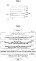
- FIG. 2 an example of a manufacturing method of a heat insulating glass unit for vehicle according to the embodiment of the present invention having the above-described features will be described.
- the heat insulating glass unit 100 illustrated in FIG. 1 is employed and a manufacturing method thereof will be described.
- FIG. 2 schematically illustrates an example of a flow of the manufacturing method of the heat insulating glass unit for vehicle according to the embodiment.
- the manufacturing method includes a step of preparing a glass plate (step S110), a step of arranging a color tone compensation film on a first surface of the glass plate (step S120), a step of arranging a transparent conductive layer above the color tone compensation film (step S130), a step of arranging an adhesion improving layer above the transparent conductive layer (step S140), a step of arranging an upper part layer above the adhesion improving layer (step S150), and a step of performing a post heat treatment (step S160).
- the step S140 i.e. arranging the adhesion improving layer may be omitted.
- the step S160 i.e. the post heat treatment may be omitted.
- a glass plate 110 i.e. a single glass plate is prepared.
- a composition of the glass plate 110 is not particularly limited, and the glass plate 110 may be configured with a soda lime glass, a quartz glass, a borosilicate glass, or an alkali-free glass.
- a color tone compensation film 120 is arranged on a first surface 112 of the glass plate 110.
- the color tone compensation film 120 may be formed of a plurality of layers including a first layer 122 and a second layer 126.
- the first layer 122 that is closer to the glass plate 110 is preferably configured with a material mainly including an oxide or an oxynitride including at least one of Ti, Nb, Ta, Zn, Al, In, Si, and Zr, for example.
- the first layer 122 may be, for example, a layer mainly including a titanium oxide in which silica is doped (silica-doped titania).
- the second layer 126 may be a layer mainly including silica.
- the first layer 122 and the second layer 126 are formed, for example, by a sputtering method, a vacuum evaporation method, an ion plating method, a chemical vapor phase film deposition method, or a wet film deposition method, or the like.
- the first and second layers 122, 126 are preferably formed by using a sputtering method. This is because an environmental burden of the sputtering method is small and a layer obtained by the sputtering method has a relatively uniform thickness.
- the sputtering method includes a DC sputtering method, an AC sputtering method, a DC pulse sputtering method, a high frequency sputtering method, a high frequency superposition DC sputtering method, and the like.
- a magnetron sputtering method may be employed as the sputtering method.
- the first layer 122 is deposited with a thickness of, for example, 3 nm - 40 nm
- the second layer 126 is deposited with a thickness of, for example, 5 nm - 35 nm.
- a transparent conductive layer 130 mainly including ITO is arranged on the color tone compensation film 120.
- the transparent conductive layer 130 may be deposited by using various sputtering methods in the same way as the case of the color tone compensation film 120.
- the transparent conductive layer 130 is an ITO layer
- the glass plate 110 upon depositing the transparent conductive layer 130 by a sputtering method, is not preferably heated during the deposition.
- a temperature of the glass plate 110 during the deposition of the ITO layer by a sputtering method is preferably 100 °C or less.
- the heat treatment temperature for crystallization falls, for example, within a range of 80 °C - 170 °C. According to this method, an ITO layer with low resistance can be obtained.
- step S160 the above-described heat treatment (in the following, referred to as a "crystallization heat treatment”) may be performed after deposition for all layers (See step S160, which will be described later).
- an adhesion improving layer 140 is preferably arranged on the transparent conductive layer 130.
- the adhesion improving layer 140 is configured with, for example, a metallic oxide, such as cerium oxide, zinc oxide or the like.
- the method of forming the adhesion improving layer 140 is not particularly limited.
- the adhesion improving layer 140 may be formed by directly depositing metallic oxide using a conventional method such as various sputtering methods.
- the metallic oxide may be, for example, zinc oxide, or cerium oxide.
- the adhesion improving layer 140 may be formed, for example, by depositing a metallic film using a conventional method such as a sputtering method, and then oxygenizing the metallic film.
- the metallic film may be, for example, zinc or cerium.
- the oxidation treatment for a metallic film may be performed in the same process as for the crystallization heat treatment for ITO in the previous step (step S130).
- the oxidation treatment for the metallic film may be performed after deposition for all layers (See step S160, which will be described later).
- Step S140 may be omitted.
- an upper part layer 150 is arranged.
- the upper part layer 150 is arranged on the adhesion improving layer 140 when the adhesion improving layer 140 is present, and is arranged on the transparent conductive layer 130 when the adhesion improving layer 140 is not present.
- the upper part layer 150 may be configured with a material mainly including silica.
- the upper part layer 150 may be deposited using various sputtering methods in the same way as the case of the other layers, such as the color tone compensation film 120.
- the entire glass plate 110 may be subjected to the heat treatment (referred to as a "post heat treatment"). Accordingly, the transparent conductive layer 130 and the upper part layer 150 can be formed to be of few defects. However, it is optional whether the post heat treatment is performed. For example, in the above-described step S130, when the crystallization heat treatment has already been performed, the post heat treatment can be omitted.
- the post heat treatment is performed, for example, in air at a temperature of 550 °C to 750 °C, for about 1 minute to 30 minutes.
- a bending process is performed for the heat insulating glass unit 100, obtained as above.
- This process is typically performed by means of performing the heat treatment for the heat insulating glass unit 100.
- the temperature of the heat treatment typically falls within a range of 550 °C - 750 °C.
- the heat treatment temperature for the bending process overlaps with the temperature of the above-described post heat treatment. Therefore, the post heat treatment and the heat treatment of the bending process may be performed simultaneously.
- Step S160 When the post heat treatment is performed at Step S160, it is not preferable to configure the first layer 122 of the color tone compensation film 120 with tin oxide. This is because when the first layer 122 is configured with tin oxide, a breakage or a crack is likely to occur in the first layer 122 after the heat treatment.
- the heat insulating glass unit 100 can be manufactured.
- another layer for example, alumina, tantalum oxide, silicon nitride, zircon-boron oxide, and the like
- the manufacturing method of the heat insulating glass unit 100 has been described briefly.
- the above-described manufacturing method is merely an example, and it is obvious for a person skilled in the art that the heat insulating glass unit according to the embodiment of the present invention can be manufactured by another manufacturing method.
- sample 1 A sample of the heat insulating glass unit (referred to as a "sample 1") was manufactured with a method described as follows.
- a glass plate with a thickness of 3.5 mm (UVFL: by Asahi Glass Company, limited) was prepared.
- titanium oxide including silica (amount of silica was 8 mass%)(refraction index for a light with a wavelength of 630 nm was 2.1537) was deposited.
- a silica-doped titania target with the amount of silica of 8 mass% was used, and a targeted film thickness was 10 nm.
- a silica layer (refraction index for a light with a wavelength of 630 nm was 1.4620) was deposited.
- a targeted film thickness was 35 nm.
- an ITO layer was deposited on the color tone compensation film (silica-doped titania layer and silica layer), as the transparent conductive layer.
- the targeted film thickness was 150 nm. Note that upon deposition, the glass plate was not heated. According to the above-described operation, an amorphous ITO layer was obtained. At a later time, an ITO layer that was crystallized by the post heat treatment (refraction index at a wavelength of 630 nm was 1.7606) was formed.
- a silica layer (refraction index at a wavelength of 630 nm was 1.4620) was deposited.
- a targeted film thickness was 55 nm.
- the glass plate was heated at 650 °C for 7 minutes.
- the sample 1 was obtained.
- Example 2 A sample of the heat insulating glass unit (referred to as a "sample 2") was manufactured using the same method as Example 1.
- Example 2 the thickness of the silica layer as the upper part layer was 95 nm.
- the other conditions were the same as in the case of Example 1.
- Example 3 A sample of the heat insulating glass unit (referred to as a "sample 3") was manufactured using the same method as Example 1.
- Example 3 as the upper part layer, a silica layer in which zirconia is doped (zirconia-doped silica layer)(refraction index at a wavelength of 630 nm was 1.6831) was deposited. A dope amount of zirconia was 33 mol% of the upper part layer. A targeted thickness of the upper part layer was 60 nm. The other conditions were the same as in the case of Example 1.
- sample 4 A sample of the heat insulating glass unit (referred to as a "sample 4") was manufactured with a method described as follows.
- a glass plate with a thickness of 3.5 mm (UVFL: by Asahi Glass Company, limited) was prepared.
- an ITO layer was deposited on a surface of the glass plate, as the transparent conductive layer.
- a targeted film thickness was 150 nm. Note that upon deposition the glass plate was not heated. According to the above-described operation, an amorphous ITO layer was obtained.
- a silica layer was deposited on the ITO layer (transparent conductive layer), as the upper part layer.
- a targeted film thickness was 80 nm.
- the glass plate was heated at 650 °C for 7 minutes.
- the sample 4 was obtained.
- sample 5 A sample of the heat insulating glass unit (referred to as a "sample 5") was manufactured using the same method as the comparative example 1.
- a silica layer in which zirconia is doped (zirconia-doped silica layer) was deposited.
- a dope amount of zirconia was 33 mol% with respect to the upper part layer.
- a thickness of the upper part layer was 80 nm.
- the other conditions were the same as in the case of the comparative example 1.
- sample 6 A sample of the heat insulating glass unit (referred to as a "sample 6") was manufactured using the same method as the comparative example 1.
- the thickness of the ITO layer was 135 nm.
- a silicon nitride layer (refraction index at a wavelength of 630 nm was 2.0898) was formed.
- a thickness of the upper part layer was 46 nm. The other conditions were the same as in the case of the comparative example 1.
- Example 7 A sample of the heat insulating glass unit (referred to as a "sample 7") was manufactured using the same method as Example 1.
- the upper part layer had a two-layered configuration including a ZrBO (first upper part layer) and SiO 2 (silica)(second upper part layer).
- a thickness of the ZrBO layer was 30 nm
- a thickness of the silica layer was 30 nm.
- the other conditions were the same as in the case of Example 1.
- the obtained reflection color was indicated in the CIE 1976 L*a*b color space (Illuminant D65, 2° field of view).
- An incident angle (°) is an inclination angle of the incident light from a line normal to the upper part layer of the sample.
- FIG. 3 illustrates reflection color, which is generated upon irradiating with light at the respective incident angles, plotted in color coordinates in the color space for the samples 1 - 3, and 7.
- FIG. 4 illustrates reflection color, which is generated upon irradiating with light at the respective incident angles, plotted in color coordinates in the color space for the samples 4 - 6.
- the region “A” is defined as a range where a* is -5 to 0, and b* is -7.5 to 4.
- the region “A” is defined as a region that does not create a strange impression from the reflection color, based on experiences of the inventors of glass members for vehicles. Typically, in the case of a glass member for vehicle, as the reflection color, colors near white to light blue tend to be preferred to colors of white to pink. Therefore, the region “A” tends to be rather broad on the side of the light blue region (lower left region of the origin.
- a spectrophotometer (U4100: by Hitachi, limited) was used.
- the respective samples are irradiated with light from the upper part layer side.
- a visible light reflectance and a visible light transmittance for the respective samples were measured.
- the measurement was performed in compliance with JIS A5759.
- emissivity for the samples was measured by using an emissivity meter (TSS-5X: by Japan Sensor Corporation).
- any of the visible light reflectance, the visible light transmittance and the emissivity for the samples 1-3 and 7, is within a proper range as a heat insulating glass unit for vehicle. In this way, it is found that the samples 1-3 and 7 can be applied to a glass member for vehicle.
- Example 8 A sample of the heat insulating glass unit (referred to as a "sample 8") was manufactured using the same method as Example 1.
- Example 5 a glass plate with a thickness of 4.0 mm (VFL: by Asahi Glass Company, limited) was used, and an adhesion improving layer of zinc oxide (thickness of 5 nm) was formed between the ITO layer and the upper part layer.
- the adhesion improving layer was formed by a general sputtering method.
- a thickness of the first layer was 8.3 nm
- a thickness of the second layer was 41 nm
- a thickness of the ITO layer (transparent conductive layer) was 154 nm
- a thickness of the upper part layer was 55.5 nm.
- sample 9 A sample of the heat insulating glass unit (referred to as a "sample 9") was manufactured using the same method as the above-described example 3.
- Example 6 a glass plate with a thickness of 4.0 mm (VFL: by Asahi Glass Company, limited) was used. A thickness of the first layer was 9.5 nm, a thickness of the second layer was 38 nm, a thickness of the ITO layer (transparent conductive layer) was 154 nm, and a thickness of the upper part layer was 58 nm.
- VFL by Asahi Glass Company, limited
- Reflection colors were measured by the above-described method using the samples 7 to 9 before and after the Taber's test (incident angle was 5°). Moreover, using a hazemeter (MODEL Hz-2: by Suga Test Instruments Co., Ltd.), a total light transmittance and a haze ratio for the samples 7 to 9 before and after the abrading Taber's test were measured.
- a hazemeter MODEL Hz-2: by Suga Test Instruments Co., Ltd.
- an item of "distance between coordinates" indicates a difference between color coordinates before abrasion process and color coordinates after abrasion process. Therefore, a small distance between coordinates means a small change in the color coordinates before and after the abrasion process.
- FIG. 5 illustrates color coordinates of reflection color before and after the abrasion process for the sample 7.
- FIG. 6 illustrates color coordinates of reflection color before and after the abrasion process for the sample 8.
- FIG. 7 illustrates color coordinates of reflection color before and after the abrasion process for the sample 9.
- arrows indicate directions of change from coordinates before the abrasion process to coordinates after the abrasion process.
- the heat insulating glass unit according to the embodiment is, upon being applied to a member that is subjected to wear due to repeated raising and lowering, such as a side glass member of a vehicle, considered to still have the effect of suppressing the angle dependence of reflection color, even if the upper part layer becomes thinner with time.
- sample 10 A sample of the heat insulating glass unit (referred to as a "sample 10") was manufactured using the same method as the above-described example 1.
- Example 7 the first layer was a non-doped titania (titanium oxide)(refraction index at a wavelength of 630 nm was 2.4347). A thickness of the first layer was 6 nm. Moreover, a thickness of the second layer was 39 nm. The other conditions were the same as in the case of Example 1.
- Example 11 A sample of the heat insulating glass unit (referred to as a "sample 11") was manufactured using the same method as Example 7. In Example 8, a thickness of an upper part layer was 95 nm. The other conditions were the same as in Example 7.
- TABLE 15 shows the layer configurations of the samples 10 and 11 as a whole: [TABLE 15] sample layer configuration glass plate color tone compensation film transparent conductive layer exfoliation preventing layer upper part layer first layer second layer 10 UVFL (3.5 titania (6 nm) silica (39 nm) ITO (150 nm) - silica (55 nm) mm) 11 UVFL (3.5 mm) titania (6 nm) silica (39 nm) ITO (150 nm) - silica (55 nm)
- FIG. 8 illustrates reflection color, which is generated upon irradiating with light at the respective incident angles, plotted in color coordinates in the color space for the samples 10 and 11.
- reflection color of the heat insulating glass unit is preferably white to a color close to pale blue (the origin to a slight lower left region). In terms of such reflection color, it can be said that the sample 10 is preferred to the sample 11.
- the reflection color tends to approach border lines that define the region "A" (specifically, a lower limit line of the a* value and an upper limit line of the b* value).
- the thickness of the upper part layer in the heat insulating glass unit is preferably 60 nm or less.
- the present invention can be used for a glass member for vehicle, a window glass member of a building, and the like.
Landscapes
- Chemical & Material Sciences (AREA)
- Engineering & Computer Science (AREA)
- Life Sciences & Earth Sciences (AREA)
- Chemical Kinetics & Catalysis (AREA)
- General Chemical & Material Sciences (AREA)
- Geochemistry & Mineralogy (AREA)
- Materials Engineering (AREA)
- Organic Chemistry (AREA)
- Mechanical Engineering (AREA)
- Surface Treatment Of Glass (AREA)
- Laminated Bodies (AREA)
Abstract
Description
- The disclosure herein generally relates to a heat insulating glass unit for vehicle.
- Heat insulating glass units that are used for vehicles, such as cars, and that do not lose heat inside vehicles to the outside of the vehicles in winter (Patent Document 1) have been known.
-
Patent Document 1 discloses a heat insulating glass unit manufactured by forming a multilayered film configured with an indium tin oxide (ITO) and a silica (SiO2) layer on a glass substrate. The heat insulating glass unit disclosed inPatent Document 1 has a feature that a visible light transmittance is high and the heat insulating performance is excellent. - [PTL 1] Japanese Unexamined Patent Application Publication No.
2004-149400 - However, the above-described heat insulating glass unit has a problem such that color characteristics as viewed exhibit angle dependence. That is, the above-described heat insulating glass unit has a tendency that a color of a reflected light (reflection color) varies by a viewing direction. For example, when the heat insulating glass unit is viewed from a first direction, the heat insulating glass unit appears blue, but when the heat insulating glass unit is viewed from a second direction, the heat insulating glass unit appears yellow. Because the above-described angle dependence of reflection color for the heat insulating glass unit creates a strange impression to a user who views the heat insulating glass unit, it is preferable to control the angle dependence as much as possible.
- The present invention was made in view of such a problem, and it is an object of the present invention to provide a heat insulating glass unit in which the angle dependence of reflection color is improved.
- In the present invention, a heat insulating glass unit for vehicle including a glass plate; a color tone compensation film arranged on at least one surface of the glass plate; a transparent conductive layer arranged on the color tone compensation film, and mainly including an indium tin oxide (ITO); and an upper part layer arranged on the transparent conductive layer, a refraction index for a light with a wavelength of 630 nm being 1.7 or less, the color tone compensation film having at least a first layer and a second layer, the first layer being arranged at a position closer to the glass plate than the second layer, and a refraction index of the first layer for a light with a wavelength of 630 nm being greater than a refraction index of the second layer for a light with a wavelength of 630 nm, is provided.
- According to an aspect of the present invention, a heat insulating glass unit in which angle dependence of reflection color is improved can be provided.
- Other objects and further features of embodiments will become apparent from the following detailed description when read in conjunction with the accompanying drawings, in which:
- [
FIGURE 1 ]
FIG. 1 is a cross sectional diagram schematically depicting a configuration of a heat insulating glass unit for vehicle according to an embodiment of the present invention. - [
FIGURE 2 ]
FIG. 2 is a diagram schematically illustrating an example of a flowchart of a manufacturing method for the heat insulating glass unit for vehicle according to the embodiment of the present invention. - [
FIGURE 3 ]
FIG. 3 is a diagram in which reflection colors occurring when irradiating with a light at respective incident angles are plotted in color coordinates in a color space for Samples 1 - 3 and 7. - [
FIGURE 4 ]
FIG. 4 is a diagram in which reflection colors occurring when irradiating with a light at respective incident angles are plotted in color coordinates in the color space for Samples 4 - 6. - [
FIGURE 5 ]
FIG. 5 is a diagram in which reflection colors before and after an abrasion process for the upper part layer are plotted in color coordinates in the color space forSample 7. - [
FIGURE 6 ]
FIG. 6 is a diagram in which reflection colors before and after the abrasion process for the upper part layer are plotted in color coordinates in the color space forSample 8. - [
FIGURE 7 ]
FIG. 7 is a diagram in which reflection colors before and after the abrasion process for the upper part layer are plotted in color coordinates in the color space for Sample 9. - [
FIGURE 8 ]
FIG. 8 is a diagram in which reflection colors occurring when irradiating with a light at respective incident angles are plotted in color coordinates in the color space forSamples - In the following, with reference to drawings, an embodiment of the present invention will be described.
-
FIG. 1 schematically illustrates a cross section of a heat insulating glass unit for vehicle according to an embodiment of the present invention. - As illustrated in
FIG. 1 , the heatinsulating glass unit 100 includes aglass plate 110, a colortone compensation film 120, a transparentconductive layer 130, anadhesion improving layer 140, and anupper part layer 150. - The
glass plate 110 has afirst surface 112 and a second surface 114. Respective members (layers), which will be described in the following, are arranged on thefirst surface 112 side. Theglass plate 110 is configured with a single piece of glass, termed as single glass (single sheet of glass or a glass pane). - The color
tone compensation film 120 is arranged on thefirst surface 112 of theglass plate 110. The colortone compensation film 120 has a role of adjusting angle dependence of reflection color of the heatinsulating glass unit 100 by controlling a refraction index of one layer or two or more layers included in the colortone compensation film 120. - In Example illustrated in
FIG. 1 , the colortone compensation film 120 is configured with two layers, i.e. afirst layer 122 and asecond layer 126 from the side adjacent to theglass plate 110. In the above-described configuration, thefirst layer 122 has a refraction index greater than that of thesecond layer 126 for a light with a wavelength of 630 nm. - However, this is merely an example, and the color
tone compensation film 120 may be configured with three layers or more. - The transparent
conductive layer 130 is arranged above the colortone compensation film 120. The transparentconductive layer 130 is configured with a material mainly including an indium tin oxide (ITO). In the present application, the phrase "layer 'A' mainly includes material 'B'" means that a layer 'A' includes a material 'B' of 50 mass % or more. - The refraction index of the transparent
conductive layer 130 for a light with wavelength of 630 nm falls, for example, within a range of 1.7 to 1.8. - The
adhesion improving layer 140 is arranged between the transparentconductive layer 130 and theupper part layer 150, and has a role of suppressing an exfoliation at an interface between both layers. Theadhesion improving layer 140 is configured, for example, by a metal oxide such as a tin oxide, a zinc oxide, a cerium oxide, and the like. Note that the arrangement of theadhesion improving layer 140 is optional, and theadhesion improving layer 140 may be omitted. - The
upper part layer 150 is arranged above the transparent conductive layer 130 (furthermore, when theadhesion improving layer 140 exists, above the adhesion improving layer 140). In the present application, the term "upper part" in the "upper part layer" means being arranged at a far side from the transparentconductive layer 130 with respect to theglass plate 110. Therefore, the expression of the "upper part layer" does not necessarily mean that theupper part layer 150 is oriented as an uppermost layer in the application with respect to the ground. - The
upper part layer 150 has a role of protecting the transparentconductive layer 130 and enhancing durability of the heatinsulating glass unit 100. - However, the
upper part layer 150 is required to be arranged so as not to have adverse effects on color characteristics of the heatinsulating glass unit 100 and the angle dependence thereof. Therefore, theupper part layer 150 is configured so that the refraction index for a light with wavelength of 630 nm is 1.7 or less. Theupper part layer 150 may be configured, for example, by a material mainly including SiO2. - The heat insulating
glass unit 100 having the above-described configuration exerts excellent heat insulating properties. For example, an emissivity of the heat insulatingglass unit 100 is 0.45 or less. Therefore, when the heat insulatingglass unit 100 is applied to, for example, a side glass, a rear glass, and/or a roof glass of an automobile (in the following, they will be referred to as "glass members" as a whole), it becomes possible to prevent heat inside a vehicle from being released to the outside of the vehicle in winter. Moreover, because according to the low emissivity film, re-radiation to the indoor side is reduced, it becomes possible to prevent the temperature inside the vehicle from increasing in summer. - Moreover, the heat insulating
glass unit 100 can significantly control the angle dependence of reflection color according to thecolor compensation film 120 and further interactions between the colortone compensation film 120, the transparentconductive layer 130, theadhesion improving layer 140, and the upper part layer 150 (arrangement of theadhesion improving layer 140 is optional). Therefore, when the heat insulatingglass unit 100 is applied to, for example, glass members of automobiles or the like, it becomes possible to significantly control variation of color characteristics depending on a viewing direction. - Furthermore, because the heat insulating
glass unit 100 has theupper part layer 150 that functions as a protection layer, it becomes possible to enhance the durability of the heat insulatingglass unit 100. For example, when the heat insulatingglass unit 100 is applied to a side glass of an automobile, an occurrence of a scratch when moving the side glass up and down for opening/closing can be reduced significantly. - Especially, when the
upper part layer 150 is mainly configured with silica (SiO2) in the heat insulatingglass unit 100, even if a thinning (wear) occurs in theupper part layer 150, the effect of controlling variation of reflection color depending on a viewing direction continues to be maintained. - Next, respective members configuring the heat insulating glass unit for vehicle according to the embodiment will be described in detail. In the following description, when indicating the respective members, for clarification, the reference numerals used in
FIG. 1 will be used. - The
glass plate 110 of the heat insulatingglass unit 100 is not particularly limited, and may be, for example, a soda lime glass, a quartz glass, a borosilicate glass, an alkali-free glass or the like. - Visible light transmittance, solar radiation transmittance, and transmittance for light with wavelength of 1500 nm are preferably 70% - 90%, 40% - 65%, and 35% - 60%, respectively. Moreover, the
glass plate 110 may be an ultraviolet protection glass that can shield ultraviolet light. Note that any of the above-described values are obtained by measuring with a measurement method prescribed in JIS. - A shape of the
glass plate 110 is not necessarily planar. Theglass plate 110 may be curved. Moreover, theglass plate 110 may be colorless or colored. Moreover, a thickness of theglass plate 110 may fall within a range of 2 mm - 6 mm, for example. - The color
tone compensation film 120 has a role of adjusting an angle dependence of reflection color of the heat insulatingglass unit 100. - As described above, the color
tone compensation film 120 is configured with a plurality of layers including at least thefirst layer 122 and thesecond layer 126. - In this case, the
first layer 122 closer to theglass plate 110 has a greater refraction index for a light with a wavelength of 630 nm than thesecond layer 126. For example, thefirst layer 122 has a refraction index for a light with a wavelength of 630 nm that falls within a range of 1.7 - 2.5. The refraction index of the first layer preferably falls within a range of 1.8 - 2.3, and more preferably falls within a range of 1.8 - 2.2. - The
second layer 126 has a refraction index for a light with a wavelength of 630 nm that is 1.6 or less. The refraction index of the second layer is preferably 1.55 or less. - The
first layer 122 mainly includes an oxide or an oxynitride including at least one of Ti, Nb, Ta, Zn, Al, In, Si, and Zr, for example. Especially, among these, an oxide or an oxynitride including at least one of Ti, Nb and Zn, and In is preferable. Thefirst layer 122 may be, for example, Ti in which silica of 0.1 mass% to 10 mass% is doped. - When the
first layer 122 is configured with tin oxide, a crack is likely to occur in thefirst layer 122 during a subsequent heating process. Therefore, when the manufacturing process of the heat insulatingglass unit 100 includes a heat treatment step, it is not preferable to configure thefirst layer 122 with tin oxide. - A thickness of the
first layer 122 falls, for example, within a range of 3 nm - 40 nm, and preferably a range of 5 nm - 35 nm. - The
second layer 126 may also be configured with a material mainly including any of SiO2, SiON, or MgF2, for example. - A thickness of the
second layer 126 falls, for example, within a range of 5 nm - 50 nm, and preferably a range of 10 nm - 45 nm. - The transparent
conductive layer 130 is configured with a material mainly including an indium tin oxide (ITO). ITO has a function of reflecting infrared light. - ITO may include an additive. Such an additive may be, for example, Ga, Zn, Al, Nb, and/or the like.
- A mass fraction of tin oxide in the ITO falls within a range of 5% - 12.5% of total mass, and preferably falls within a range of 6.5% - 11% of total mass. For tin oxide mass fractions of 12.5% or less, resistance tends to decrease as amount of tin oxide increases.
- Moreover, the transparent
conductive layer 130 may include, in addition to ITO, another material of less than 50 mass% at maximum. Such a material may be, for example, sodium, lead, iron, and/or the like. - A thickness of the transparent
conductive layer 130 falls, for example, within a range of 100 nm - 200 nm, and preferably a range of 120 nm - 170 nm. - A refraction index of the transparent
conductive layer 130 for a light with a wavelength of 630 nm typically falls within a range of 1.7 - 1.8. - The transparent
conductive layer 130 may be configured by, for example, depositing an amorphous ITO layer on the colortone compensation film 120, and crystallizing the layer. According to the crystallization, a heat treatment temperature falls, for example, within a range of 80 °C - 170 °C. By the above-described method, an ITO layer with a low resistance can be obtained. - The
adhesion improving layer 140 is arranged as necessary. By arranging theadhesion improving layer 140, a peel strength may be enhanced between the transparentconductive layer 130 and theupper part layer 150. - The
adhesion improving layer 140 may be configured with a metallic oxide such as tin oxide, zinc oxide, cerium oxide and/or the like. - A thickness of the
adhesion improving layer 140 falls, for example, within a range of 1 nm - 10 nm. - The
upper part layer 150 is arranged in order to protect a layer existing below theupper part layer 150, e.g. the transparent conductive layer 130 (and/or the adhesion improving layer 140). For example, by arranging theupper part layer 150 above the transparent conductive layer 130 (and/or the adhesion improving layer 140), it becomes possible to enhance an oxidation resistance of the transparent conductive layer 130 (and/or the adhesion improving layer 140). Moreover, by arranging theupper part layer 150, an abrasion resistance is enhanced, and it becomes possible to control an occurrence of a thinning (wear), a crack or the like in the transparent conductive layer 130 (and/or the adhesion improving layer 140). - Moreover, when the
upper part layer 150 is arranged appropriately, it becomes possible to enhance the transmittance in the visual light range of the heat insulatingglass unit 100. - The
upper part layer 150 is preferably configured with a material with a refraction index, for a light with a wavelength of 630 nm, of 1.7 or less, and more preferably a material with a refraction index of 1.55 or less. Such a material includes silica (SiO2), SiON, and MgF2. Theupper part layer 150 may be a layer mainly including, for example, silica. In this case, it is possible to enhance heat resistance of the transparentconductive layer 130. Moreover, in the case of the layer mainly including silica, even if a thinning (wear) occurs in theupper part layer 150, it is still possible to maintain the same effect of controlling the angle dependence of reflection color as the heat insulatingglass unit 100 in the initial period. - The
upper part layer 150 may be, for example, a layer of silica in which zirconia is doped (zirconia-doped silica). A dope amount of zirconia with respect to the entireupper part layer 150 preferably falls within a range of 5 mol% - 40 mol%, for example. Moreover, theupper part layer 150 may have a multilayered configuration. Typically, theupper part layer 150 can have a multilayered configuration including a first upper part layer outside and a second upper part layer inside. The first upper part layer includes preferably at least one selection from a group including ZrBO, ZrO2, Ta2O5, Al2O3, TiO2, Nb2O5, SiN, and BN. The second upper part layer is preferably SiO2. For example, preferably, the multilayered configuration includes an inner layer (second upper part layer) mainly including SiO2, and an outer layer (first upper part layer) of ZrBO. - A thickness of the
upper part layer 150 preferably falls, for example, within a range of 20 nm - 100 nm. The thickness of theupper part layer 150 more preferably falls, for example, within a range of 20 nm - 60 nm. When the thickness of theupper part layer 150 is 60 nm or less, as described below, an effect whereby it becomes relatively easier to control reflection color from the heat insulatingglass unit 100 can be obtained. - The heat insulating
glass unit 100 preferably has an emissivity that falls within a range of 0.1 - 0.45. In the heat insulatingglass unit 100 having such an emissivity, it becomes possible to significantly decrease the heat transmission coefficient for light with wavelengths of infrared and far-infrared. - Note that, in the embodiment, reflection color from the heat insulating
glass unit 100 is represented by CIE1976 L*a*b color space (Illuminant D65, field of view of 2°) . - Especially, the
heat insulating unit 100 according to the embodiment has a feature that a color space of a reflected light generated when a light enters with an incident angle within a range of 0° - 80° is included in a region of -5 ≤ a* ≤ 0 and -7.5 ≤ b* ≤ 4. Therefore, in the heat insulatingglass unit 100, it is possible to significantly control the angle dependence of reflection color. - The heat insulating
glass unit 100 can be applied, for example, to a glass member of a vehicle. Such a glass member may be, for example, a front windshield, a rear windshield, a side glass, and a roof glass. - When the heat insulating
glass unit 100 is used as a front windshield, the heat insulating glass is combined with another glass plate via an intermediate film to prepare a laminated glass. In such a case, the heat insulating glass is arranged on a vehicle interior surface of the intermediate film, and used so that a coating surface such as the transparent conductive layer is directed to the vehicle interior side. Therefore, heat inside the vehicle can be prevented from dissipating to the outside of the vehicle, and heat of solar light absorbed outside the vehicle and by the intermediate film can be prevented from entering the vehicle. - Furthermore, the heat insulating glass unit of the embodiment can also be applied to a window glass of a building, or a glass member of a refrigerating apparatus, a freezer, a show case, and the like.
- When the heat insulating glass unit according to the embodiment is mounted on a vehicle, the heat insulating glass unit is arranged so that a surface on which a film is formed is the vehicle interior side. According to the above-described configuration, the heat insulating glass unit in which the angle dependence is improved can be provided. In addition, the heat insulating glass unit may also be mounted so that the surface on which the film is formed is the vehicle exterior side. According to the above-described configuration, the angle dependence of the heat insulating glass unit is improved, and a heat shield effect can further be obtained.
- Next, with reference to
FIG. 2 , an example of a manufacturing method of a heat insulating glass unit for vehicle according to the embodiment of the present invention having the above-described features will be described. In the following, as an example, the heat insulatingglass unit 100 illustrated inFIG. 1 is employed and a manufacturing method thereof will be described. -
FIG. 2 schematically illustrates an example of a flow of the manufacturing method of the heat insulating glass unit for vehicle according to the embodiment. - As illustrated in
FIG. 2 , the manufacturing method includes a step of preparing a glass plate (step S110), a step of arranging a color tone compensation film on a first surface of the glass plate (step S120), a step of arranging a transparent conductive layer above the color tone compensation film (step S130), a step of arranging an adhesion improving layer above the transparent conductive layer (step S140), a step of arranging an upper part layer above the adhesion improving layer (step S150), and a step of performing a post heat treatment (step S160). The step S140, i.e. arranging the adhesion improving layer may be omitted. Similarly, the step S160, i.e. the post heat treatment may be omitted. - In the following, the respective steps will be described in detail. Note that in the following description, when indicating the respective members, for clarification, the reference numerals used in
FIG. 1 will be used. - First, a
glass plate 110, i.e. a single glass plate is prepared. - As described above, a composition of the
glass plate 110 is not particularly limited, and theglass plate 110 may be configured with a soda lime glass, a quartz glass, a borosilicate glass, or an alkali-free glass. - Next, a color
tone compensation film 120 is arranged on afirst surface 112 of theglass plate 110. - As described above, the color
tone compensation film 120 may be formed of a plurality of layers including afirst layer 122 and asecond layer 126. Among them, thefirst layer 122 that is closer to theglass plate 110 is preferably configured with a material mainly including an oxide or an oxynitride including at least one of Ti, Nb, Ta, Zn, Al, In, Si, and Zr, for example. Thefirst layer 122 may be, for example, a layer mainly including a titanium oxide in which silica is doped (silica-doped titania). Thesecond layer 126 may be a layer mainly including silica. - The
first layer 122 and thesecond layer 126 are formed, for example, by a sputtering method, a vacuum evaporation method, an ion plating method, a chemical vapor phase film deposition method, or a wet film deposition method, or the like. The first andsecond layers - The sputtering method includes a DC sputtering method, an AC sputtering method, a DC pulse sputtering method, a high frequency sputtering method, a high frequency superposition DC sputtering method, and the like. As the sputtering method, a magnetron sputtering method may be employed.
- The
first layer 122 is deposited with a thickness of, for example, 3 nm - 40 nm, and thesecond layer 126 is deposited with a thickness of, for example, 5 nm - 35 nm. - Next, a transparent
conductive layer 130 mainly including ITO is arranged on the colortone compensation film 120. - The transparent
conductive layer 130 may be deposited by using various sputtering methods in the same way as the case of the colortone compensation film 120. When the transparentconductive layer 130 is an ITO layer, upon depositing the transparentconductive layer 130 by a sputtering method, theglass plate 110 is not preferably heated during the deposition. For example, a temperature of theglass plate 110 during the deposition of the ITO layer by a sputtering method is preferably 100 °C or less. - The heat treatment temperature for crystallization falls, for example, within a range of 80 °C - 170 °C. According to this method, an ITO layer with low resistance can be obtained.
- Note that the above-described heat treatment (in the following, referred to as a "crystallization heat treatment") may be performed after deposition for all layers (See step S160, which will be described later).
- Next, an
adhesion improving layer 140 is preferably arranged on the transparentconductive layer 130. Theadhesion improving layer 140 is configured with, for example, a metallic oxide, such as cerium oxide, zinc oxide or the like. - The method of forming the
adhesion improving layer 140 is not particularly limited. - The
adhesion improving layer 140 may be formed by directly depositing metallic oxide using a conventional method such as various sputtering methods. The metallic oxide may be, for example, zinc oxide, or cerium oxide. - Alternatively, the
adhesion improving layer 140 may be formed, for example, by depositing a metallic film using a conventional method such as a sputtering method, and then oxygenizing the metallic film. The metallic film may be, for example, zinc or cerium. - In the latter case, the oxidation treatment for a metallic film may be performed in the same process as for the crystallization heat treatment for ITO in the previous step (step S130). Alternatively, the oxidation treatment for the metallic film may be performed after deposition for all layers (See step S160, which will be described later).
- Note that Step S140 may be omitted.
- Next, an
upper part layer 150 is arranged. Theupper part layer 150 is arranged on theadhesion improving layer 140 when theadhesion improving layer 140 is present, and is arranged on the transparentconductive layer 130 when theadhesion improving layer 140 is not present. Theupper part layer 150 may be configured with a material mainly including silica. - The
upper part layer 150 may be deposited using various sputtering methods in the same way as the case of the other layers, such as the colortone compensation film 120. - After forming the
upper part layer 150, theentire glass plate 110 may be subjected to the heat treatment (referred to as a "post heat treatment"). Accordingly, the transparentconductive layer 130 and theupper part layer 150 can be formed to be of few defects. However, it is optional whether the post heat treatment is performed. For example, in the above-described step S130, when the crystallization heat treatment has already been performed, the post heat treatment can be omitted. - The post heat treatment is performed, for example, in air at a temperature of 550 °C to 750 °C, for about 1 minute to 30 minutes.
- When the heat insulating
glass unit 100 is applied to a front windshield for vehicle or the like, a bending process is performed for the heat insulatingglass unit 100, obtained as above. This process is typically performed by means of performing the heat treatment for the heat insulatingglass unit 100. The temperature of the heat treatment typically falls within a range of 550 °C - 750 °C. - The heat treatment temperature for the bending process overlaps with the temperature of the above-described post heat treatment. Therefore, the post heat treatment and the heat treatment of the bending process may be performed simultaneously.
- When the post heat treatment is performed at Step S160, it is not preferable to configure the
first layer 122 of the colortone compensation film 120 with tin oxide. This is because when thefirst layer 122 is configured with tin oxide, a breakage or a crack is likely to occur in thefirst layer 122 after the heat treatment. - According to the above-described processes, the heat insulating
glass unit 100 can be manufactured. Note that on theupper part layer 150, another layer (for example, alumina, tantalum oxide, silicon nitride, zircon-boron oxide, and the like) may be formed. - As described above, the manufacturing method of the heat insulating
glass unit 100 has been described briefly. However, the above-described manufacturing method is merely an example, and it is obvious for a person skilled in the art that the heat insulating glass unit according to the embodiment of the present invention can be manufactured by another manufacturing method. - Next, examples of the present invention will be described.
- A sample of the heat insulating glass unit (referred to as a "
sample 1") was manufactured with a method described as follows. - First, a glass plate with a thickness of 3.5 mm (UVFL: by Asahi Glass Company, limited) was prepared. Next, by a sputtering method, on a surface of the glass plate, as the first layer of the color tone compensation film, titanium oxide including silica (amount of silica was 8 mass%)(refraction index for a light with a wavelength of 630 nm was 2.1537) was deposited. For the deposition, a silica-doped titania target with the amount of silica of 8 mass% was used, and a targeted film thickness was 10 nm.
- Next, by a sputtering method, on the first layer (silica-doped titania layer), as the second layer of the color tone compensation film, a silica layer (refraction index for a light with a wavelength of 630 nm was 1.4620) was deposited. A targeted film thickness was 35 nm.
- Next, by a sputtering method, on the color tone compensation film (silica-doped titania layer and silica layer), as the transparent conductive layer, an ITO layer was deposited. The targeted film thickness was 150 nm. Note that upon deposition, the glass plate was not heated. According to the above-described operation, an amorphous ITO layer was obtained. At a later time, an ITO layer that was crystallized by the post heat treatment (refraction index at a wavelength of 630 nm was 1.7606) was formed.
- Next, by a sputtering method, on the ITO layer (transparent conductive layer), as the upper part layer, a silica layer (refraction index at a wavelength of 630 nm was 1.4620) was deposited. A targeted film thickness was 55 nm.
- Afterwards, as the post heat treatment, the glass plate was heated at 650 °C for 7 minutes.
- According to the above-described processes, the
sample 1 was obtained. - A sample of the heat insulating glass unit (referred to as a "
sample 2") was manufactured using the same method as Example 1. - In Example 2, the thickness of the silica layer as the upper part layer was 95 nm. The other conditions were the same as in the case of Example 1.
- A sample of the heat insulating glass unit (referred to as a "
sample 3") was manufactured using the same method as Example 1. - In Example 3, as the upper part layer, a silica layer in which zirconia is doped (zirconia-doped silica layer)(refraction index at a wavelength of 630 nm was 1.6831) was deposited. A dope amount of zirconia was 33 mol% of the upper part layer. A targeted thickness of the upper part layer was 60 nm. The other conditions were the same as in the case of Example 1.
- A sample of the heat insulating glass unit (referred to as a "
sample 4") was manufactured with a method described as follows. - First, a glass plate with a thickness of 3.5 mm (UVFL: by Asahi Glass Company, limited) was prepared. Next, by a sputtering method, on a surface of the glass plate, as the transparent conductive layer, an ITO layer was deposited. A targeted film thickness was 150 nm. Note that upon deposition the glass plate was not heated. According to the above-described operation, an amorphous ITO layer was obtained.
- Next, by a sputtering method, on the ITO layer (transparent conductive layer), as the upper part layer, a silica layer was deposited. A targeted film thickness was 80 nm.
- Afterwards, as the post heat treatment, the glass plate was heated at 650 °C for 7 minutes.
- According to the above-described processes, the
sample 4 was obtained. - A sample of the heat insulating glass unit (referred to as a "
sample 5") was manufactured using the same method as the comparative example 1. - In the comparative example 2, as the upper part layer, a silica layer in which zirconia is doped (zirconia-doped silica layer) was deposited. A dope amount of zirconia was 33 mol% with respect to the upper part layer. A thickness of the upper part layer was 80 nm. The other conditions were the same as in the case of the comparative example 1.
- A sample of the heat insulating glass unit (referred to as a "
sample 6") was manufactured using the same method as the comparative example 1. - In the comparative example 3, the thickness of the ITO layer (transparent conductive layer) was 135 nm. Moreover, as the upper part layer, by a sputtering method, a silicon nitride layer (refraction index at a wavelength of 630 nm was 2.0898) was formed. A thickness of the upper part layer was 46 nm. The other conditions were the same as in the case of the comparative example 1.
- A sample of the heat insulating glass unit (referred to as a "
sample 7") was manufactured using the same method as Example 1. - In Example 4, the upper part layer had a two-layered configuration including a ZrBO (first upper part layer) and SiO2 (silica)(second upper part layer). A thickness of the ZrBO layer was 30 nm, and a thickness of the silica layer was 30 nm. The other conditions were the same as in the case of Example 1.
- TABLE 1, in the following, shows the layer configurations of the
samples 1 to 7 as a whole.[TABLE 1] sample layer configuration glass plate color tone compensation film transparent conductive layer exfoliation preventing layer upper part layer first layer second layer 1 UVFL (3.5 mm) silica doped titania (10 nm) silica (35 nm) ITO (150 nm) - silica (55 nm) 2 UVFL (3.5 mm) silica doped titania (10 nm) silica (35 nm) ITO (150 nm) - silica (95 nm) 3 UVFL (3.5 mm) silica doped titania (10 nm) silica (35 nm) ITO (150 nm) - zirconia doped silica (60 nm) 4 UVFL (3.5 mm) - - ITO (150 nm) - silica (80 nm) 5 UVFL (3.5 mm) - - ITO (150 nm) - zirconia doped silica (80 nm) 6 UVFL (3.5 mm) - - ITO (135 nm) - SiN (80 nm) 7 UVFL (3.5 mm) silica doped titania (10 nm) silica (35 nm) ITO (150 nm) - ZrBO (30 nm) and silica (30 nm) - Next, using the
respective samples 1 to 7, the following characteristic evaluation was performed. - Using the respective samples, by the following method, the angle dependence of reflection color was evaluated.
- Using a spectrometer (V570ARM-500N by JASCO Corporation), irradiating with a visible light (wavelength of 300 nm to 800 nm) at a predetermined angle (5° to 80°) from the upper part layer side, an obtained reflection color was measured.
- The obtained reflection color was indicated in the CIE 1976 L*a*b color space (Illuminant D65, 2° field of view).
- Results of measurements for the
samples 1 to 7 are shown in the following TABLEs 2 to 8. An incident angle (°) is an inclination angle of the incident light from a line normal to the upper part layer of the sample.[TABLE 2] incident angle (°) reflection color L* a* b* 5 29.4104 -0.2838 0.4924 10 29.5065 -0.4782 0.6940 20 29.8473 -1.0733 1.2237 30 30.6226 -2.0198 1.8058 40 32.2829 -3.0349 1.9549 50 35.7801 -3.6026 1.3318 60 42.7509 -3.4406 0.3346 70 55.1763 -3.0007 -0.0799 80 74.2192 -2.5774 0.2089 [TABLE 3] incident angle (°) reflection color L* a* b* 5 23.0132 -3.8486 -0.8822 10 22.9372 -3.4854 -0.9276 20 22.8461 -2.5119 -0.9308 30 23.2005 -1.4169 -0.4883 40 24.8881 -1.0786 0.7672 50 29.2543 -1.9809 2.3162 60 37.8924 -3.3718 2.8467 70 52.2314 -4.1470 2.1860 80 72.8599 -3.6967 1.3260 [TABLE 4] incident angle (°) reflection color L* a* b* 5 34.2601 -0.7842 -0.4275 10 34.2691 -0.7771 -0.3620 20 34.3626 -0.8659 -0.1052 30 34.7633 -1.2903 0.4082 40 35.9419 -2.1549 0.9889 50 38.8159 -3.1337 1.1193 60 44.9727 -3.5994 0.5264 70 52.4892 -3.4076 -0.1439 80 74.7779 -2.8291 -0.1215 [TABLE 5] incident angle (°) reflection color L* a* b* 5 27.3255 -12.2460 7.1272 10 27.2673 -12.4006 6.6553 20 27.1343 -12.6015 5.0701 30 27.1347 -12.1423 2.1664 40 27.9165 -10.2384 -1.6169 50 30.9563 -6.9386 -4.7776 60 38.4900 -3.9022 -5.5075 70 52.3888 -2.7444 -3.6606 80 72.9586 -2.5889 -1.2039 [TABLE 6] incident angle (°) reflection color L* a* b* 5 38.5657 -11.9248 19.4326 10 38.5527 -12.4030 19.1721 20 38.5193 -13.6114 18.0436 30 38.5383 -14.8826 15.3076 40 38.9440 -15.1993 10.6412 50 40.7040 -13.5868 4.9450 60 45.7857 -10.1409 0.3657 70 56.7360 -6.6476 -1.2071 80 74.9056 -4.2210 -0.4363 [TABLE 7] incident angle (°) reflection color L* a* b* 5 50.0499 -8.5970 -8.0217 10 49.8595 -8.3277 -8.5218 20 49.3200 -7.4922 -9.9067 30 48.5652 -6.0497 -11.8062 40 47.9539 -4.0798 -13.5334 50 48.3068 -1.9870 -14.0281 60 51.2493 -0.6308 -12.0047 70 59.3700 -0.8873 -6.9663 80 75.2344 -2.0748 -1.2982 [TABLE 8] incident angle (°) reflection color L* a* b* 5 31.4478 -1.3521 -0.8262 10 31.4427 -1.2724 -0.7724 20 31.5064 -1.1625 -0.5236 30 31.9025 -1.3373 0.0636 40 33.1758 -2.0370 0.8784 50 36.3390 -3.0404 1.3684 60 43.0296 -3.6623 1.0894 70 55.2322 -3.5664 0.5395 80 74.1712 -2.9066 0.4168 -
FIG. 3 illustrates reflection color, which is generated upon irradiating with light at the respective incident angles, plotted in color coordinates in the color space for the samples 1 - 3, and 7. Similarly,FIG. 4 illustrates reflection color, which is generated upon irradiating with light at the respective incident angles, plotted in color coordinates in the color space for the samples 4 - 6. - In
FIG. 3 andFIG. 4 , for the respective samples, variations in the reflection color occurring when the light incident angle changes from 5° to 70° can be grasped quantitatively. Especially, in the case where irrespective of the incident angle, any colors of the reflection light reflected at a heat insulating glass unit are included in a region "A", it can be said that in the heat insulating glass unit the angle dependence of reflection color is significantly controlled. - The region "A" is defined as a range where a* is -5 to 0, and b* is -7.5 to 4. The region "A" is defined as a region that does not create a strange impression from the reflection color, based on experiences of the inventors of glass members for vehicles. Typically, in the case of a glass member for vehicle, as the reflection color, colors near white to light blue tend to be preferred to colors of white to pink. Therefore, the region "A" tends to be rather broad on the side of the light blue region (lower left region of the origin.
- From
FIG. 3 , is was found that for the samples 1-3, and thesample 7, even if the incident angle changes from 5° to 70°, the color coordinates of the reflection color remain inside the region "A". Therefore, it was confirmed that for the samples 1-3, the angle dependence of reflection color from samples was significantly controlled. - In
FIG. 4 , it is found that for the samples 4-6, when the incident angle changes from 5 to 70, the color coordinates of reflected light greatly deviate from the region "A", and tend to be distributed in an upper left region greatly deviated from the origin (region of strong yellow to yellow-green). Therefore, it was confirmed that for the samples 4-6, the angle dependence of reflection color from samples was great, and there was a problem of a strange impression created upon being viewed. - Next, using the samples 1-3, and the
sample 7, a visible light reflectance, a visible light transmittance, and emissivity were measured. - For the measurement, a spectrophotometer (U4100: by Hitachi, limited) was used. The respective samples are irradiated with light from the upper part layer side. Within a range of wavelength of light of 300 nm to 2500 nm, a visible light reflectance and a visible light transmittance for the respective samples were measured. The measurement was performed in compliance with JIS A5759.
- An emissivity for the samples (hemispheric emissivity) was measured by using an emissivity meter (TSS-5X: by Japan Sensor Corporation).
- Results of measurement obtained for the
sample 1 are shown in TABLE 9 as a whole:[TABLE 9] incident angle (°) visible light reflectance (%) visible light transmittance (%) hemispheric emissivity 0 6.3 75.4 0.16 - Results of measurement obtained for the
sample 2 are shown in TABLE 10 as a whole:[TABLE 10] incident angle (°) visible light reflectance (%) visible light transmittance (%) hemispheric emissivity 0 4.9 77.2 0.17 - Results of measurement obtained for the
sample 3 are shown in TABLE 11 as a whole:[TABLE 11] incident angle (°) visible light reflectance (%) visible light transmittance (%) hemispheric emissivity 0 7.7 73.7 0.16 - Results of measurement obtained for the
sample 7 are shown in TABLE 12 as a whole:[TABLE 12] incident angle (°) visible light reflectance (%) visible light transmittance (%) hemispheric emissivity 0 6.8 74.8 0.17 - From the above-described results, it is found that any of the visible light reflectance, the visible light transmittance and the emissivity for the samples 1-3 and 7, is within a proper range as a heat insulating glass unit for vehicle. In this way, it is found that the samples 1-3 and 7 can be applied to a glass member for vehicle.
- A sample of the heat insulating glass unit (referred to as a "
sample 8") was manufactured using the same method as Example 1. - In Example 5, a glass plate with a thickness of 4.0 mm (VFL: by Asahi Glass Company, limited) was used, and an adhesion improving layer of zinc oxide (thickness of 5 nm) was formed between the ITO layer and the upper part layer. The adhesion improving layer was formed by a general sputtering method.
- Moreover, a thickness of the first layer was 8.3 nm, a thickness of the second layer was 41 nm, a thickness of the ITO layer (transparent conductive layer) was 154 nm, and a thickness of the upper part layer was 55.5 nm.
- A sample of the heat insulating glass unit (referred to as a "sample 9") was manufactured using the same method as the above-described example 3.
- In Example 6, a glass plate with a thickness of 4.0 mm (VFL: by Asahi Glass Company, limited) was used. A thickness of the first layer was 9.5 nm, a thickness of the second layer was 38 nm, a thickness of the ITO layer (transparent conductive layer) was 154 nm, and a thickness of the upper part layer was 58 nm.
- TABLE 13, in the following, shows the layer configurations of the
samples 8 and 9 as a whole:[TABLE 13] sample layer configuration glass plate color tone compensation film transparent conductive layer exfoliation preventing layer upper part layer first layer second layer 8 UVFL (3.5 mm) silica doped titania (8.3 nm) silica (41 nm) ITO (154 nm) zinc oxide (5 nm) silica (55.5 nm) 9 UVFL (3.5 mm) silica doped titania silica (38 nm) ITO (154 nm) - zirconia doped silica (9.5 nm) (60 nm) - Next, using the
samples 7 to 9, the following characteristic evaluation was performed. - An effect on reflection color from changes (decreases) of the abrasion resistance of samples or the thickness of the upper part layer was evaluated.
- First, using a Taber's abrasion test apparatus, an upper part layer of samples was abraded. A sample was arranged horizontally on an apparatus table, so that the upper part layer of the sample was directed upward. Then, with a load of 4.9 N from above, an abraded surface of the apparatus (abrasion wheel: C1800XF) was pressed against the sample. In this state, the sample was abraded by rotating the abrading surface of the apparatus at 1000 rotations.
- Reflection colors were measured by the above-described method using the
samples 7 to 9 before and after the Taber's test (incident angle was 5°). Moreover, using a hazemeter (MODEL Hz-2: by Suga Test Instruments Co., Ltd.), a total light transmittance and a haze ratio for thesamples 7 to 9 before and after the abrading Taber's test were measured. - TABLE 14, in the following, shows results of evaluation for the
samples 7 to 9 as a whole.[TABLE 14] sample Total light transmit tance (%) chromaticity coordinate Haze value L* a* b* distance between coordinates sample 7 before abrading 76.37 31.61 -0.09 -2.92 0.10 after abrading 74.16 33.74 0.41 -2.20 1.17 difference -2.21 2.13 0.50 0.72 2.30 1.06 sample 8before abrading 78.1 31.24 -1.26 -4.47 0.06 after abrading 76.5 32.47 -1.26 -4.23 0.98 difference -1.6 1.23 0.00 0.24 1.25 0.92 sample 9 before abrading 75.0 35.84 -2.62 0.65 0.10 after abrading 72.9 37.09 -2.01 -0.35 1.32 difference -2.1 1.25 0.62 -1.00 1.71 1.22 - In TABLE 14, an item of "distance between coordinates" indicates a difference between color coordinates before abrasion process and color coordinates after abrasion process. Therefore, a small distance between coordinates means a small change in the color coordinates before and after the abrasion process.
- Moreover,
FIG. 5 illustrates color coordinates of reflection color before and after the abrasion process for thesample 7.FIG. 6 illustrates color coordinates of reflection color before and after the abrasion process for thesample 8.FIG. 7 illustrates color coordinates of reflection color before and after the abrasion process for the sample 9. InFIGs. 5 - 7 , arrows indicate directions of change from coordinates before the abrasion process to coordinates after the abrasion process. - From the above-described results, it was found that for the
samples 7 to 9, even if the upper part layer became thinner, there was almost no effect on reflection color. - Therefore, the heat insulating glass unit according to the embodiment is, upon being applied to a member that is subjected to wear due to repeated raising and lowering, such as a side glass member of a vehicle, considered to still have the effect of suppressing the angle dependence of reflection color, even if the upper part layer becomes thinner with time.
- A sample of the heat insulating glass unit (referred to as a "
sample 10") was manufactured using the same method as the above-described example 1. - In Example 7, the first layer was a non-doped titania (titanium oxide)(refraction index at a wavelength of 630 nm was 2.4347). A thickness of the first layer was 6 nm. Moreover, a thickness of the second layer was 39 nm. The other conditions were the same as in the case of Example 1.
- A sample of the heat insulating glass unit (referred to as a "
sample 11") was manufactured using the same method as Example 7. In Example 8, a thickness of an upper part layer was 95 nm. The other conditions were the same as in Example 7. - TABLE 15, in the following, shows the layer configurations of the
samples [TABLE 15] sample layer configuration glass plate color tone compensation film transparent conductive layer exfoliation preventing layer upper part layer first layer second layer 10 UVFL (3.5 titania (6 nm) silica (39 nm) ITO (150 nm) - silica (55 nm) mm) 11 UVFL (3.5 mm) titania (6 nm) silica (39 nm) ITO (150 nm) - silica (55 nm) - Next, using the
samples 10 to 11, using the above-described method, the angle dependence of reflection color was evaluated. - Results of measurements for the
samples [TABLE 16] incident angle (°) reflection color L* a* b* 5 29.0071 -0.0417 -2.5307 10 29.0746 -0.1149 -2.4252 20 29.3377 -0.3648 -2.1251 30 30.0157 -0.8204 -1.7159 40 31.6179 -1.3836 -1.3714 50 35.1755 -1.8323 -1.1828 60 42.3594 -2.0971 -0.9123 70 55.0522 -2.4187 -0.2514 80 74.2457 -2.5345 0.4542 [TABLE 17] incident angle (°) reflection color L* a* b* 5 23.5186 -4.8379 1.8537 10 23.4632 -4.7772 1.9588 20 23.4081 -4.5978 2.2444 30 23.7383 -4.3783 2.6517 40 25.2600 -4.3081 3.0423 50 29.3479 -4.4411 3.0547 60 37.7794 -4.5386 2.4706 70 52.1057 -4.4285 1.7178 80 72.8166 -3.7096 1.1729 -
FIG. 8 illustrates reflection color, which is generated upon irradiating with light at the respective incident angles, plotted in color coordinates in the color space for thesamples - From
FIG. 8 , it was found that for any of thesamples samples - In
FIG. 8 , it is found that for thesample 10, any of the reflection colors at the respective incident angles exist near the origin of the color coordinates. However, for thesample 11, the color coordinates at the respective incident angles tend to be biased to the upper left part with respect to the region "A", i.e. a region of thin yellow-green to thin yellow. - As described above, taking into account applying the heat insulating glass unit according to the present invention to a glass member for vehicle, reflection color of the heat insulating glass unit is preferably white to a color close to pale blue (the origin to a slight lower left region). In terms of such reflection color, it can be said that the
sample 10 is preferred to thesample 11. - Moreover, in the
sample 11, the reflection color tends to approach border lines that define the region "A" (specifically, a lower limit line of the a* value and an upper limit line of the b* value). According to the above-described property, when the thickness of the upper part layer is greater than 60 nm, as in thesample 10, it may be difficult to design the reflection color within a desired range. Therefore, it can be said that taking into account the ease of design of reflection color, the thickness of the upper part layer in the heat insulating glass unit is preferably 60 nm or less. - The present invention can be used for a glass member for vehicle, a window glass member of a building, and the like.
- The present application is based on and claims the benefit of priority of Japanese Priority Application No.
2015-096245 filed on May 11, 2015 -
- 100
- heat insulating glass unit
- 110
- glass plate
- 112
- first surface
- 114
- second surface
- 120
- color tone compensation film
- 122
- first layer
- 126
- second layer
- 130
- transparent conductive layer
- 140
- adhesion improving layer
- 150
- upper part layer
Claims (12)
- A heat insulating glass unit for vehicle comprising:a glass plate;a color tone compensation film arranged on at least one surface of the glass plate;a transparent conductive layer arranged on the color tone compensation film, and mainly including an indium tin oxide (ITO); andan upper part layer arranged on the transparent conductive layer, a refraction index for a light with a wavelength of 630 nm being 1.7 or less,wherein the color tone compensation film has at least a first layer and a second layer,wherein the first layer is arranged at a position closer to the glass plate than the second layer, andwherein a refraction index of the first layer for a light with a wavelength of 630 nm is greater than a refraction index of the second layer for a light with a wavelength of 630 nm.
- The heat insulating glass unit for vehicle according to claim 1,
wherein the transparent conductive layer has a thickness in a range of 100 nm to 200 nm. - The heat insulating glass unit for vehicle according to claim 1 or 2,
wherein the upper part layer has a thickness of 60 nm or less. - The heat insulating glass unit for vehicle according to any one of claims 1 to 3 further comprising:an adhesion improving layer between the transparent conductive layer and the upper part layer.
- The heat insulating glass unit for vehicle according to any one of claims 1 to 4,
wherein the upper part layer mainly includes SiO2. - The heat insulating glass unit for vehicle according to any one of claims 1 to 4;
wherein the upper part layer includes at least
a first upper part layer arranged on an uppermost layer, a refraction index being greater than 1.7; and
a second upper part layer arranged below the first upper part layer, a refraction index being 1.7 or less. - The heat insulating glass unit for vehicle according to claim 6,
wherein the first upper part layer includes at least one selection from a group including ZrBO, ZrO2, Ta2O5, Al2O3, TiO2, Nb2O5, SiN, and BN. - The heat insulating glass unit for vehicle according to claim 6,
wherein the second upper part layer mainly includes SiO2. - The heat insulating glass unit for vehicle according to any one of claims 1 to 8,
wherein the first layer includes an oxide or an oxynitride including at least one of Ti, Nb, Ta, Zn, Al, In, Si, and Zr. - The heat insulating glass unit for vehicle according to any one of claims 1 to 8,
wherein the second layer mainly includes SiO2. - The heat insulating glass unit for vehicle according to any one of claims 1 to 8,
wherein the first layer includes an oxide or an oxynitride including at least one of Ti, Nb, Ta, Zn, Al, In, Si, and Zr, and
wherein the second layer mainly includes SiO2. - The heat insulating glass unit for vehicle according to any one of claims 1 to 11,
wherein an emissivity is 0.45 or less.
Applications Claiming Priority (2)
| Application Number | Priority Date | Filing Date | Title |
|---|---|---|---|
| JP2015096245 | 2015-05-11 | ||
| PCT/JP2016/061738 WO2016181739A1 (en) | 2015-05-11 | 2016-04-11 | Insulated glass unit for vehicles |
Publications (3)
| Publication Number | Publication Date |
|---|---|
| EP3296275A1 true EP3296275A1 (en) | 2018-03-21 |
| EP3296275A4 EP3296275A4 (en) | 2019-02-06 |
| EP3296275B1 EP3296275B1 (en) | 2021-03-17 |
Family
ID=57247961
Family Applications (1)
| Application Number | Title | Priority Date | Filing Date |
|---|---|---|---|
| EP16792464.6A Active EP3296275B1 (en) | 2015-05-11 | 2016-04-11 | Insulated glass unit for vehicles |
Country Status (5)
| Country | Link |
|---|---|
| US (1) | US10618838B2 (en) |
| EP (1) | EP3296275B1 (en) |
| JP (1) | JP6760273B2 (en) |
| CN (1) | CN107531561A (en) |
| WO (1) | WO2016181739A1 (en) |
Cited By (1)
| Publication number | Priority date | Publication date | Assignee | Title |
|---|---|---|---|---|
| CN109397790A (en) * | 2018-11-27 | 2019-03-01 | 宁波全亮照明科技有限公司 | Chinese herbaceous peony the gear multi-functional composite glass structure of lifting and its manufacturing method |
Families Citing this family (2)
| Publication number | Priority date | Publication date | Assignee | Title |
|---|---|---|---|---|
| JP2019199877A (en) * | 2017-04-20 | 2019-11-21 | Agc株式会社 | Heat insulating structure |
| KR102381911B1 (en) | 2021-05-18 | 2022-04-01 | (주)인터코닉스 | Protective film for preventing splash marks on the exterior of a car's windshield which can be constructed easily |
Family Cites Families (58)
| Publication number | Priority date | Publication date | Assignee | Title |
|---|---|---|---|---|
| US3881043A (en) | 1971-06-21 | 1975-04-29 | Ppg Industries Inc | Laminated safety windshields |
| AU616736B2 (en) | 1988-03-03 | 1991-11-07 | Asahi Glass Company Limited | Amorphous oxide film and article having such film thereon |
| EP0486475B1 (en) * | 1988-03-03 | 1997-12-03 | Asahi Glass Company Ltd. | Amorphous oxide film and article having such film thereon |
| JPH03187736A (en) | 1989-03-07 | 1991-08-15 | Asahi Glass Co Ltd | Heat rays barrier glass |
| US5318830A (en) * | 1991-05-29 | 1994-06-07 | Central Glass Company, Limited | Glass pane with reflectance reducing coating |
| US5667880A (en) * | 1992-07-20 | 1997-09-16 | Fuji Photo Optical Co., Ltd. | Electroconductive antireflection film |
| JPH07210085A (en) | 1994-01-18 | 1995-08-11 | Toppan Printing Co Ltd | Seal |
| JPH09188547A (en) * | 1996-01-05 | 1997-07-22 | Sekisui Chem Co Ltd | Laminated glass and interlayer therefor |
| GB2324098A (en) * | 1997-04-08 | 1998-10-14 | Pilkington Plc | Solar control coated glass |
| JP4013329B2 (en) * | 1997-05-21 | 2007-11-28 | 旭硝子株式会社 | Laminate and glass laminate for window |
| US6165598A (en) * | 1998-08-14 | 2000-12-26 | Libbey-Owens-Ford Co. | Color suppressed anti-reflective glass |
| US6309753B1 (en) * | 1998-08-31 | 2001-10-30 | Corning Incorporated | Coated ultraviolet absorbing glass |
| FR2787440B1 (en) | 1998-12-21 | 2001-12-07 | Saint Gobain Vitrage | TRANSPARENT SUBSTRATE HAVING AN ANTI-REFLECTIVE COATING |
| US6797388B1 (en) * | 1999-03-18 | 2004-09-28 | Ppg Industries Ohio, Inc. | Methods of making low haze coatings and the coatings and coated articles made thereby |
| FR2800998B1 (en) * | 1999-11-17 | 2002-04-26 | Saint Gobain Vitrage | TRANSPARENT SUBSTRATE HAVING AN ANTI-REFLECTIVE COATING |
| US20040005482A1 (en) * | 2001-04-17 | 2004-01-08 | Tomio Kobayashi | Antireflection film and antireflection layer-affixed plastic substrate |
| US20030035939A1 (en) * | 2001-08-06 | 2003-02-20 | Nippon Sheet Glass Co., Ltd. | Windowpane for head up display and method for manufacturing the same |
| JP2004013081A (en) | 2002-06-11 | 2004-01-15 | Nikon Corp | Composite optical element, method for manufacturing the same, and optical apparatus |
| GB0216787D0 (en) | 2002-07-19 | 2002-08-28 | Pilkington Plc | Laminated glazing panel |
| JP2004149400A (en) | 2002-09-02 | 2004-05-27 | Asahi Glass Co Ltd | Heat insulating glass and method for manufacture the same |
| US20050196623A1 (en) * | 2004-03-03 | 2005-09-08 | Mckown Clem S.Jr. | Solar control coated glass composition |
| WO2005114271A1 (en) | 2004-05-20 | 2005-12-01 | Fujifilm Corporation | Polarization plate with antireflection function, process for producing the same, and image display unit utilizing the same |
| US8679302B2 (en) * | 2005-11-14 | 2014-03-25 | Guardian Industries Corp. | Silicon titanium oxide coating, coated article including silicon titanium oxide coating, and method of making the same |
| US20070108043A1 (en) * | 2005-11-14 | 2007-05-17 | Guardian Industries Corp. | Sputtering target including titanium silicon oxide and method of making coated article using the same |
| US20070113881A1 (en) * | 2005-11-22 | 2007-05-24 | Guardian Industries Corp. | Method of making solar cell with antireflective coating using combustion chemical vapor deposition (CCVD) and corresponding product |
| FR2898295B1 (en) * | 2006-03-10 | 2013-08-09 | Saint Gobain | TRANSPARENT ANTIREFLECTION SUBSTRATE WITH NEUTRAL COLOR IN REFLECTION |
| WO2008123553A1 (en) | 2007-04-04 | 2008-10-16 | Asahi Glass Company, Limited | Antifouling member and laminated glass using the same |
| US8630040B2 (en) * | 2007-10-30 | 2014-01-14 | 3M Innovative Properties Company | Multi-component films for optical display filters |
| US8350451B2 (en) * | 2008-06-05 | 2013-01-08 | 3M Innovative Properties Company | Ultrathin transparent EMI shielding film comprising a polymer basecoat and crosslinked polymer transparent dielectric layer |
| US7998586B2 (en) * | 2008-11-19 | 2011-08-16 | Ppg Industries Ohio, Inc. | Undercoating layers providing improved topcoat functionality |
| US9366783B2 (en) * | 2009-12-21 | 2016-06-14 | Ppg Industries Ohio, Inc. | Silicon thin film solar cell having improved underlayer coating |
| US20110146768A1 (en) * | 2009-12-21 | 2011-06-23 | Ppg Industries Ohio, Inc. | Silicon thin film solar cell having improved underlayer coating |
| FR2956659B1 (en) * | 2010-02-22 | 2014-10-10 | Saint Gobain | LAYER COATED VERTICAL SUBSTRATE WITH IMPROVED MECHANICAL STRENGTH |
| JP2011191338A (en) | 2010-03-11 | 2011-09-29 | Etsumi Kogaku:Kk | Transparent coloring article |
| FR2963343B1 (en) * | 2010-07-28 | 2012-07-27 | Saint Gobain | GLAZING WITH COATING AGAINST CONDENSATION |
| FR2968774B1 (en) * | 2010-12-10 | 2013-02-08 | Essilor Int | OPTICAL ARTICLE COMPRISING A LOW REFLECTIVE ANTIREFLECTION COATING IN THE ULTRAVIOLET DOMAIN AND THE VISIBLE DOMAIN |
| FR2973023B1 (en) * | 2011-03-25 | 2019-08-02 | Saint-Gobain Glass France | MULTIPLE INSULATION GLAZING COMPRISING TWO LOW EMISSIVE STACKS |
| WO2012133832A1 (en) * | 2011-03-31 | 2012-10-04 | 旭硝子株式会社 | Organic led element, light-transmitting substrate, and method for producing light-transmitting substrate |
| BE1019988A3 (en) * | 2011-05-24 | 2013-03-05 | Agc Glass Europe | TRANSPARENT VERRIER SUBSTRATE CARRYING A COATING OF SUCCESSIVE LAYERS. |
| BE1020051A3 (en) | 2011-07-04 | 2013-04-02 | Agc Glass Europe | AUTOMOBILE GLAZING. |
| CN202643562U (en) * | 2011-12-13 | 2013-01-02 | 信义超薄玻璃(东莞)有限公司 | Heat-protecting low-emissivity glass |
| FR2987618B1 (en) * | 2012-03-05 | 2014-02-28 | Saint Gobain | ANTICONDENSATION GLAZING |
| MX358614B (en) * | 2012-03-05 | 2018-08-29 | Saint Gobain | Sheet with coating which reflects thermal radiation. |
| JP6307062B2 (en) * | 2012-03-30 | 2018-04-04 | アプライド マテリアルズ インコーポレイテッドApplied Materials,Incorporated | Transparent body used in touch panel and manufacturing method and apparatus thereof |
| JP5885595B2 (en) * | 2012-06-12 | 2016-03-15 | キヤノン株式会社 | Antireflection film, and optical element, optical system, and optical apparatus having the same |
| BR112015001314B1 (en) | 2012-08-01 | 2021-12-21 | Saint-Gobain Glass France | COMPOSITE PANEL WITH ELECTRICAL CONTACT MEANS AND METHOD TO PRODUCE COMPOSITE PANEL |
| US20140113120A1 (en) * | 2012-10-19 | 2014-04-24 | Ppg Industries Ohio, Inc. | Anti-color banding topcoat for coated articles |
| KR101820219B1 (en) * | 2013-02-20 | 2018-01-18 | 쌩-고벵 글래스 프랑스 | Panel with a coating which reflects thermal radiation |
| FR3002534B1 (en) * | 2013-02-27 | 2018-04-13 | Saint-Gobain Glass France | SUBSTRATE COATED WITH A LOW EMISSIVE STACK. |
| US9110230B2 (en) * | 2013-05-07 | 2015-08-18 | Corning Incorporated | Scratch-resistant articles with retained optical properties |
| US9703011B2 (en) * | 2013-05-07 | 2017-07-11 | Corning Incorporated | Scratch-resistant articles with a gradient layer |
| US9359261B2 (en) * | 2013-05-07 | 2016-06-07 | Corning Incorporated | Low-color scratch-resistant articles with a multilayer optical film |
| JP6470274B2 (en) * | 2013-07-05 | 2019-02-13 | エシロール アンテルナショナルEssilor International | Optical article comprising an antireflective coating having very low reflection in the visible region |
| FR3010074B1 (en) * | 2013-09-05 | 2019-08-02 | Saint-Gobain Glass France | METHOD FOR MANUFACTURING A MATERIAL COMPRISING A SUBSTRATE HAVING A FUNCTIONAL LAYER BASED ON TIN OXIDE AND INDIUM |
| FR3012133B1 (en) * | 2013-10-17 | 2021-01-01 | Saint Gobain | PROCESS FOR OBTAINING A SUBSTRATE COATED BY A STACK CONTAINING A TRANSPARENT CONDUCTIVE OXIDE LAYER |
| FR3019173B1 (en) * | 2014-03-28 | 2016-03-25 | Saint Gobain | GLAZING PROVIDED WITH A STACK OF THIN LAYERS FOR SOLAR PROTECTION |
| EP3156580B1 (en) * | 2014-06-11 | 2019-07-10 | Nippon Sheet Glass Company, Limited | Multi-layered glass unit and glass plate for multi-layered glass unit |
| EP3541762B1 (en) * | 2016-11-17 | 2022-03-02 | Cardinal CG Company | Static-dissipative coating technology |
-
2016
- 2016-04-11 EP EP16792464.6A patent/EP3296275B1/en active Active
- 2016-04-11 JP JP2017517830A patent/JP6760273B2/en active Active
- 2016-04-11 CN CN201680025368.0A patent/CN107531561A/en active Pending
- 2016-04-11 WO PCT/JP2016/061738 patent/WO2016181739A1/en active Application Filing
-
2017
- 2017-10-09 US US15/727,818 patent/US10618838B2/en active Active
Cited By (1)
| Publication number | Priority date | Publication date | Assignee | Title |
|---|---|---|---|---|
| CN109397790A (en) * | 2018-11-27 | 2019-03-01 | 宁波全亮照明科技有限公司 | Chinese herbaceous peony the gear multi-functional composite glass structure of lifting and its manufacturing method |
Also Published As
| Publication number | Publication date |
|---|---|
| CN107531561A (en) | 2018-01-02 |
| US20180043661A1 (en) | 2018-02-15 |
| EP3296275A4 (en) | 2019-02-06 |
| JP6760273B2 (en) | 2020-09-23 |
| WO2016181739A1 (en) | 2016-11-17 |
| US10618838B2 (en) | 2020-04-14 |
| EP3296275B1 (en) | 2021-03-17 |
| JPWO2016181739A1 (en) | 2018-03-01 |
Similar Documents
| Publication | Publication Date | Title |
|---|---|---|
| EP3296277B1 (en) | Heat insulating glass unit for vehicle and manufacturing method thereof | |
| EP3676652B1 (en) | Heads-up display and coating therefor | |
| KR101728620B1 (en) | Pane having a coating that reflects thermal radiation | |
| EP3870548B1 (en) | Glazing and method of its production | |
| JP5395065B2 (en) | Transparency for instruments | |
| CZ304663B6 (en) | Transparent substrate, glazing part, process of its manufacture and use | |
| CN111601779B (en) | Solar control glass panel comprising two titanium nitride based layers | |
| CN104203856A (en) | Solar control glazing | |
| EA025674B1 (en) | Solar control glazing with low solar factor | |
| EA030714B1 (en) | Pane with coating which reflects thermal radiation | |
| RU2690459C1 (en) | Heated multilayer glass with thin inner glass and thin outer glass | |
| US11319245B2 (en) | Coated protective glazing | |
| KR20210145225A (en) | Articles having high visible light reflectance and neutral color | |
| CN104619668A (en) | Substrate provided with a stack having thermal properties and an absorbent layer | |
| CN109564305A (en) | Substrate with hot property lamination comprising at least one layer is rich in silicon-zirconium nitride of zirconium, purposes and its preparation | |
| US10618838B2 (en) | Heat insulating glass unit for vehicle | |
| KR20170016891A (en) | Glazing for solar protection provided with thin-film coatings | |
| KR102042587B1 (en) | Insulating glazing having a high light-transmission coefficient | |
| US20220204397A1 (en) | Method of reducing the emissivity of a coated glass article | |
| US20240150232A1 (en) | Vehicle window with an ir-reflective coating with a discontinuous metallic layer of metal nanocrystals |
Legal Events
| Date | Code | Title | Description |
|---|---|---|---|
| STAA | Information on the status of an ep patent application or granted ep patent |
Free format text: STATUS: THE INTERNATIONAL PUBLICATION HAS BEEN MADE |
|
| PUAI | Public reference made under article 153(3) epc to a published international application that has entered the european phase |
Free format text: ORIGINAL CODE: 0009012 |
|
| STAA | Information on the status of an ep patent application or granted ep patent |
Free format text: STATUS: REQUEST FOR EXAMINATION WAS MADE |
|
| 17P | Request for examination filed |
Effective date: 20170905 |
|
| AK | Designated contracting states |
Kind code of ref document: A1 Designated state(s): AL AT BE BG CH CY CZ DE DK EE ES FI FR GB GR HR HU IE IS IT LI LT LU LV MC MK MT NL NO PL PT RO RS SE SI SK SM TR |
|
| AX | Request for extension of the european patent |
Extension state: BA ME |
|
| DAV | Request for validation of the european patent (deleted) | ||
| DAX | Request for extension of the european patent (deleted) | ||
| RAP1 | Party data changed (applicant data changed or rights of an application transferred) |
Owner name: AGC INC. |
|
| A4 | Supplementary search report drawn up and despatched |
Effective date: 20190108 |
|
| RIC1 | Information provided on ipc code assigned before grant |
Ipc: B32B 7/02 20190101ALI20190102BHEP Ipc: B32B 9/00 20060101ALI20190102BHEP Ipc: C03C 17/34 20060101AFI20190102BHEP Ipc: B32B 17/08 20060101ALI20190102BHEP Ipc: B60J 1/00 20060101ALI20190102BHEP |
|
| STAA | Information on the status of an ep patent application or granted ep patent |
Free format text: STATUS: EXAMINATION IS IN PROGRESS |
|
| 17Q | First examination report despatched |
Effective date: 20200624 |
|
| GRAP | Despatch of communication of intention to grant a patent |
Free format text: ORIGINAL CODE: EPIDOSNIGR1 |
|
| STAA | Information on the status of an ep patent application or granted ep patent |
Free format text: STATUS: GRANT OF PATENT IS INTENDED |
|
| INTG | Intention to grant announced |
Effective date: 20200929 |
|
| GRAS | Grant fee paid |
Free format text: ORIGINAL CODE: EPIDOSNIGR3 |
|
| GRAA | (expected) grant |
Free format text: ORIGINAL CODE: 0009210 |
|
| STAA | Information on the status of an ep patent application or granted ep patent |
Free format text: STATUS: THE PATENT HAS BEEN GRANTED |
|
| AK | Designated contracting states |
Kind code of ref document: B1 Designated state(s): AL AT BE BG CH CY CZ DE DK EE ES FI FR GB GR HR HU IE IS IT LI LT LU LV MC MK MT NL NO PL PT RO RS SE SI SK SM TR |
|
| REG | Reference to a national code |
Ref country code: GB Ref legal event code: FG4D |
|
| REG | Reference to a national code |
Ref country code: CH Ref legal event code: EP |
|
| REG | Reference to a national code |
Ref country code: DE Ref legal event code: R096 Ref document number: 602016054495 Country of ref document: DE |
|
| REG | Reference to a national code |
Ref country code: IE Ref legal event code: FG4D |
|
| REG | Reference to a national code |
Ref country code: AT Ref legal event code: REF Ref document number: 1372101 Country of ref document: AT Kind code of ref document: T Effective date: 20210415 |
|
| REG | Reference to a national code |
Ref country code: LT Ref legal event code: MG9D |
|
| PG25 | Lapsed in a contracting state [announced via postgrant information from national office to epo] |
Ref country code: NO Free format text: LAPSE BECAUSE OF FAILURE TO SUBMIT A TRANSLATION OF THE DESCRIPTION OR TO PAY THE FEE WITHIN THE PRESCRIBED TIME-LIMIT Effective date: 20210617 Ref country code: GR Free format text: LAPSE BECAUSE OF FAILURE TO SUBMIT A TRANSLATION OF THE DESCRIPTION OR TO PAY THE FEE WITHIN THE PRESCRIBED TIME-LIMIT Effective date: 20210618 Ref country code: FI Free format text: LAPSE BECAUSE OF FAILURE TO SUBMIT A TRANSLATION OF THE DESCRIPTION OR TO PAY THE FEE WITHIN THE PRESCRIBED TIME-LIMIT Effective date: 20210317 Ref country code: HR Free format text: LAPSE BECAUSE OF FAILURE TO SUBMIT A TRANSLATION OF THE DESCRIPTION OR TO PAY THE FEE WITHIN THE PRESCRIBED TIME-LIMIT Effective date: 20210317 Ref country code: BG Free format text: LAPSE BECAUSE OF FAILURE TO SUBMIT A TRANSLATION OF THE DESCRIPTION OR TO PAY THE FEE WITHIN THE PRESCRIBED TIME-LIMIT Effective date: 20210617 |
|
| REG | Reference to a national code |
Ref country code: AT Ref legal event code: MK05 Ref document number: 1372101 Country of ref document: AT Kind code of ref document: T Effective date: 20210317 |
|
| REG | Reference to a national code |
Ref country code: NL Ref legal event code: MP Effective date: 20210317 |
|
| PG25 | Lapsed in a contracting state [announced via postgrant information from national office to epo] |
Ref country code: RS Free format text: LAPSE BECAUSE OF FAILURE TO SUBMIT A TRANSLATION OF THE DESCRIPTION OR TO PAY THE FEE WITHIN THE PRESCRIBED TIME-LIMIT Effective date: 20210317 Ref country code: LV Free format text: LAPSE BECAUSE OF FAILURE TO SUBMIT A TRANSLATION OF THE DESCRIPTION OR TO PAY THE FEE WITHIN THE PRESCRIBED TIME-LIMIT Effective date: 20210317 Ref country code: SE Free format text: LAPSE BECAUSE OF FAILURE TO SUBMIT A TRANSLATION OF THE DESCRIPTION OR TO PAY THE FEE WITHIN THE PRESCRIBED TIME-LIMIT Effective date: 20210317 |
|
| PG25 | Lapsed in a contracting state [announced via postgrant information from national office to epo] |
Ref country code: NL Free format text: LAPSE BECAUSE OF FAILURE TO SUBMIT A TRANSLATION OF THE DESCRIPTION OR TO PAY THE FEE WITHIN THE PRESCRIBED TIME-LIMIT Effective date: 20210317 |
|
| PG25 | Lapsed in a contracting state [announced via postgrant information from national office to epo] |
Ref country code: AT Free format text: LAPSE BECAUSE OF FAILURE TO SUBMIT A TRANSLATION OF THE DESCRIPTION OR TO PAY THE FEE WITHIN THE PRESCRIBED TIME-LIMIT Effective date: 20210317 Ref country code: SM Free format text: LAPSE BECAUSE OF FAILURE TO SUBMIT A TRANSLATION OF THE DESCRIPTION OR TO PAY THE FEE WITHIN THE PRESCRIBED TIME-LIMIT Effective date: 20210317 Ref country code: CZ Free format text: LAPSE BECAUSE OF FAILURE TO SUBMIT A TRANSLATION OF THE DESCRIPTION OR TO PAY THE FEE WITHIN THE PRESCRIBED TIME-LIMIT Effective date: 20210317 Ref country code: EE Free format text: LAPSE BECAUSE OF FAILURE TO SUBMIT A TRANSLATION OF THE DESCRIPTION OR TO PAY THE FEE WITHIN THE PRESCRIBED TIME-LIMIT Effective date: 20210317 Ref country code: LT Free format text: LAPSE BECAUSE OF FAILURE TO SUBMIT A TRANSLATION OF THE DESCRIPTION OR TO PAY THE FEE WITHIN THE PRESCRIBED TIME-LIMIT Effective date: 20210317 |
|
| PG25 | Lapsed in a contracting state [announced via postgrant information from national office to epo] |
Ref country code: IS Free format text: LAPSE BECAUSE OF FAILURE TO SUBMIT A TRANSLATION OF THE DESCRIPTION OR TO PAY THE FEE WITHIN THE PRESCRIBED TIME-LIMIT Effective date: 20210717 Ref country code: RO Free format text: LAPSE BECAUSE OF FAILURE TO SUBMIT A TRANSLATION OF THE DESCRIPTION OR TO PAY THE FEE WITHIN THE PRESCRIBED TIME-LIMIT Effective date: 20210317 Ref country code: SK Free format text: LAPSE BECAUSE OF FAILURE TO SUBMIT A TRANSLATION OF THE DESCRIPTION OR TO PAY THE FEE WITHIN THE PRESCRIBED TIME-LIMIT Effective date: 20210317 Ref country code: PT Free format text: LAPSE BECAUSE OF FAILURE TO SUBMIT A TRANSLATION OF THE DESCRIPTION OR TO PAY THE FEE WITHIN THE PRESCRIBED TIME-LIMIT Effective date: 20210719 Ref country code: PL Free format text: LAPSE BECAUSE OF FAILURE TO SUBMIT A TRANSLATION OF THE DESCRIPTION OR TO PAY THE FEE WITHIN THE PRESCRIBED TIME-LIMIT Effective date: 20210317 |
|
| REG | Reference to a national code |
Ref country code: DE Ref legal event code: R097 Ref document number: 602016054495 Country of ref document: DE |
|
| PG25 | Lapsed in a contracting state [announced via postgrant information from national office to epo] |
Ref country code: LU Free format text: LAPSE BECAUSE OF NON-PAYMENT OF DUE FEES Effective date: 20210411 |
|
| REG | Reference to a national code |
Ref country code: BE Ref legal event code: MM Effective date: 20210430 |
|
| PLBE | No opposition filed within time limit |
Free format text: ORIGINAL CODE: 0009261 |
|
| STAA | Information on the status of an ep patent application or granted ep patent |
Free format text: STATUS: NO OPPOSITION FILED WITHIN TIME LIMIT |
|
| PG25 | Lapsed in a contracting state [announced via postgrant information from national office to epo] |
Ref country code: DK Free format text: LAPSE BECAUSE OF FAILURE TO SUBMIT A TRANSLATION OF THE DESCRIPTION OR TO PAY THE FEE WITHIN THE PRESCRIBED TIME-LIMIT Effective date: 20210317 Ref country code: ES Free format text: LAPSE BECAUSE OF FAILURE TO SUBMIT A TRANSLATION OF THE DESCRIPTION OR TO PAY THE FEE WITHIN THE PRESCRIBED TIME-LIMIT Effective date: 20210317 Ref country code: LI Free format text: LAPSE BECAUSE OF NON-PAYMENT OF DUE FEES Effective date: 20210430 Ref country code: MC Free format text: LAPSE BECAUSE OF FAILURE TO SUBMIT A TRANSLATION OF THE DESCRIPTION OR TO PAY THE FEE WITHIN THE PRESCRIBED TIME-LIMIT Effective date: 20210317 Ref country code: CH Free format text: LAPSE BECAUSE OF NON-PAYMENT OF DUE FEES Effective date: 20210430 Ref country code: AL Free format text: LAPSE BECAUSE OF FAILURE TO SUBMIT A TRANSLATION OF THE DESCRIPTION OR TO PAY THE FEE WITHIN THE PRESCRIBED TIME-LIMIT Effective date: 20210317 |
|
| 26N | No opposition filed |
Effective date: 20211220 |
|
| GBPC | Gb: european patent ceased through non-payment of renewal fee |
Effective date: 20210617 |
|
| PG25 | Lapsed in a contracting state [announced via postgrant information from national office to epo] |
Ref country code: SI Free format text: LAPSE BECAUSE OF FAILURE TO SUBMIT A TRANSLATION OF THE DESCRIPTION OR TO PAY THE FEE WITHIN THE PRESCRIBED TIME-LIMIT Effective date: 20210317 |
|
| PG25 | Lapsed in a contracting state [announced via postgrant information from national office to epo] |
Ref country code: IT Free format text: LAPSE BECAUSE OF FAILURE TO SUBMIT A TRANSLATION OF THE DESCRIPTION OR TO PAY THE FEE WITHIN THE PRESCRIBED TIME-LIMIT Effective date: 20210317 Ref country code: IE Free format text: LAPSE BECAUSE OF NON-PAYMENT OF DUE FEES Effective date: 20210411 Ref country code: GB Free format text: LAPSE BECAUSE OF NON-PAYMENT OF DUE FEES Effective date: 20210617 |
|
| PG25 | Lapsed in a contracting state [announced via postgrant information from national office to epo] |
Ref country code: IS Free format text: LAPSE BECAUSE OF FAILURE TO SUBMIT A TRANSLATION OF THE DESCRIPTION OR TO PAY THE FEE WITHIN THE PRESCRIBED TIME-LIMIT Effective date: 20210717 Ref country code: FR Free format text: LAPSE BECAUSE OF NON-PAYMENT OF DUE FEES Effective date: 20210517 |
|
| PG25 | Lapsed in a contracting state [announced via postgrant information from national office to epo] |
Ref country code: BE Free format text: LAPSE BECAUSE OF NON-PAYMENT OF DUE FEES Effective date: 20210430 |
|
| PG25 | Lapsed in a contracting state [announced via postgrant information from national office to epo] |
Ref country code: HU Free format text: LAPSE BECAUSE OF FAILURE TO SUBMIT A TRANSLATION OF THE DESCRIPTION OR TO PAY THE FEE WITHIN THE PRESCRIBED TIME-LIMIT; INVALID AB INITIO Effective date: 20160411 |
|
| PG25 | Lapsed in a contracting state [announced via postgrant information from national office to epo] |
Ref country code: CY Free format text: LAPSE BECAUSE OF FAILURE TO SUBMIT A TRANSLATION OF THE DESCRIPTION OR TO PAY THE FEE WITHIN THE PRESCRIBED TIME-LIMIT Effective date: 20210317 |
|
| PG25 | Lapsed in a contracting state [announced via postgrant information from national office to epo] |
Ref country code: MK Free format text: LAPSE BECAUSE OF FAILURE TO SUBMIT A TRANSLATION OF THE DESCRIPTION OR TO PAY THE FEE WITHIN THE PRESCRIBED TIME-LIMIT Effective date: 20210317 |
|
| PGFP | Annual fee paid to national office [announced via postgrant information from national office to epo] |
Ref country code: DE Payment date: 20240418 Year of fee payment: 9 |