EP3296183A1 - Zerstörungsfreie prüfung von eisenbahnschienen, -rädern und -achsen - Google Patents
Zerstörungsfreie prüfung von eisenbahnschienen, -rädern und -achsen Download PDFInfo
- Publication number
- EP3296183A1 EP3296183A1 EP17178642.9A EP17178642A EP3296183A1 EP 3296183 A1 EP3296183 A1 EP 3296183A1 EP 17178642 A EP17178642 A EP 17178642A EP 3296183 A1 EP3296183 A1 EP 3296183A1
- Authority
- EP
- European Patent Office
- Prior art keywords
- rails
- wheels
- test regions
- carriage
- infrared detector
- Prior art date
- Legal status (The legal status is an assumption and is not a legal conclusion. Google has not performed a legal analysis and makes no representation as to the accuracy of the status listed.)
- Granted
Links
Images


Classifications
-
- B—PERFORMING OPERATIONS; TRANSPORTING
- B61—RAILWAYS
- B61K—AUXILIARY EQUIPMENT SPECIALLY ADAPTED FOR RAILWAYS, NOT OTHERWISE PROVIDED FOR
- B61K9/00—Railway vehicle profile gauges; Detecting or indicating overheating of components; Apparatus on locomotives or cars to indicate bad track sections; General design of track recording vehicles
- B61K9/04—Detectors for indicating the overheating of axle bearings and the like, e.g. associated with the brake system for applying the brakes in case of a fault
- B61K9/06—Detectors for indicating the overheating of axle bearings and the like, e.g. associated with the brake system for applying the brakes in case of a fault by detecting or indicating heat radiation from overheated axles
-
- B—PERFORMING OPERATIONS; TRANSPORTING
- B61—RAILWAYS
- B61L—GUIDING RAILWAY TRAFFIC; ENSURING THE SAFETY OF RAILWAY TRAFFIC
- B61L23/00—Control, warning or like safety means along the route or between vehicles or trains
- B61L23/04—Control, warning or like safety means along the route or between vehicles or trains for monitoring the mechanical state of the route
- B61L23/042—Track changes detection
- B61L23/045—Rail wear
-
- B—PERFORMING OPERATIONS; TRANSPORTING
- B61—RAILWAYS
- B61K—AUXILIARY EQUIPMENT SPECIALLY ADAPTED FOR RAILWAYS, NOT OTHERWISE PROVIDED FOR
- B61K9/00—Railway vehicle profile gauges; Detecting or indicating overheating of components; Apparatus on locomotives or cars to indicate bad track sections; General design of track recording vehicles
- B61K9/08—Measuring installations for surveying permanent way
- B61K9/10—Measuring installations for surveying permanent way for detecting cracks in rails or welds thereof
-
- B—PERFORMING OPERATIONS; TRANSPORTING
- B61—RAILWAYS
- B61K—AUXILIARY EQUIPMENT SPECIALLY ADAPTED FOR RAILWAYS, NOT OTHERWISE PROVIDED FOR
- B61K9/00—Railway vehicle profile gauges; Detecting or indicating overheating of components; Apparatus on locomotives or cars to indicate bad track sections; General design of track recording vehicles
- B61K9/12—Measuring or surveying wheel-rims
-
- B—PERFORMING OPERATIONS; TRANSPORTING
- B61—RAILWAYS
- B61L—GUIDING RAILWAY TRAFFIC; ENSURING THE SAFETY OF RAILWAY TRAFFIC
- B61L23/00—Control, warning or like safety means along the route or between vehicles or trains
- B61L23/04—Control, warning or like safety means along the route or between vehicles or trains for monitoring the mechanical state of the route
- B61L23/042—Track changes detection
- B61L23/044—Broken rails
-
- G—PHYSICS
- G01—MEASURING; TESTING
- G01M—TESTING STATIC OR DYNAMIC BALANCE OF MACHINES OR STRUCTURES; TESTING OF STRUCTURES OR APPARATUS, NOT OTHERWISE PROVIDED FOR
- G01M17/00—Testing of vehicles
- G01M17/08—Railway vehicles
- G01M17/10—Suspensions, axles or wheels
-
- G—PHYSICS
- G01—MEASURING; TESTING
- G01M—TESTING STATIC OR DYNAMIC BALANCE OF MACHINES OR STRUCTURES; TESTING OF STRUCTURES OR APPARATUS, NOT OTHERWISE PROVIDED FOR
- G01M5/00—Investigating the elasticity of structures, e.g. deflection of bridges or air-craft wings
- G01M5/0025—Investigating the elasticity of structures, e.g. deflection of bridges or air-craft wings of elongated objects, e.g. pipes, masts, towers or railways
-
- G—PHYSICS
- G01—MEASURING; TESTING
- G01M—TESTING STATIC OR DYNAMIC BALANCE OF MACHINES OR STRUCTURES; TESTING OF STRUCTURES OR APPARATUS, NOT OTHERWISE PROVIDED FOR
- G01M5/00—Investigating the elasticity of structures, e.g. deflection of bridges or air-craft wings
- G01M5/0033—Investigating the elasticity of structures, e.g. deflection of bridges or air-craft wings by determining damage, crack or wear
-
- G—PHYSICS
- G01—MEASURING; TESTING
- G01M—TESTING STATIC OR DYNAMIC BALANCE OF MACHINES OR STRUCTURES; TESTING OF STRUCTURES OR APPARATUS, NOT OTHERWISE PROVIDED FOR
- G01M5/00—Investigating the elasticity of structures, e.g. deflection of bridges or air-craft wings
- G01M5/0066—Investigating the elasticity of structures, e.g. deflection of bridges or air-craft wings by exciting or detecting vibration or acceleration
-
- G—PHYSICS
- G01—MEASURING; TESTING
- G01M—TESTING STATIC OR DYNAMIC BALANCE OF MACHINES OR STRUCTURES; TESTING OF STRUCTURES OR APPARATUS, NOT OTHERWISE PROVIDED FOR
- G01M5/00—Investigating the elasticity of structures, e.g. deflection of bridges or air-craft wings
- G01M5/0075—Investigating the elasticity of structures, e.g. deflection of bridges or air-craft wings by means of external apparatus, e.g. test benches or portable test systems
-
- G—PHYSICS
- G01—MEASURING; TESTING
- G01M—TESTING STATIC OR DYNAMIC BALANCE OF MACHINES OR STRUCTURES; TESTING OF STRUCTURES OR APPARATUS, NOT OTHERWISE PROVIDED FOR
- G01M5/00—Investigating the elasticity of structures, e.g. deflection of bridges or air-craft wings
- G01M5/0091—Investigating the elasticity of structures, e.g. deflection of bridges or air-craft wings by using electromagnetic excitation or detection
-
- G—PHYSICS
- G01—MEASURING; TESTING
- G01M—TESTING STATIC OR DYNAMIC BALANCE OF MACHINES OR STRUCTURES; TESTING OF STRUCTURES OR APPARATUS, NOT OTHERWISE PROVIDED FOR
- G01M7/00—Vibration-testing of structures; Shock-testing of structures
- G01M7/02—Vibration-testing by means of a shake table
- G01M7/025—Measuring arrangements
-
- G—PHYSICS
- G01—MEASURING; TESTING
- G01N—INVESTIGATING OR ANALYSING MATERIALS BY DETERMINING THEIR CHEMICAL OR PHYSICAL PROPERTIES
- G01N25/00—Investigating or analyzing materials by the use of thermal means
- G01N25/72—Investigating presence of flaws
Definitions
- the disclosure relates to nondestructive evaluation systems and methods, and more particularly, to systems and methods for the nondestructive evaluation of railroad rails, wheels, and axles.
- test object is very large and/or is integrated into a larger structure in a manner that makes its removal difficult if not impossible to remove for remote testing in a laboratory.
- NDE tests nondestructive evaluation tests
- An advantage of NDE tests is that they do not permanently alter an object in an undesirable manner, which may render the test object useless for its intended purpose. Consequently, there is a need to develop methods and systems for NDE tests on objects without having to remove the objects from their location and environment of use.
- Nondestructive evaluation systems and methods have been developed to provide non-contact inspection of components and structures in the field to detect flaws and otherwise determine the integrity of such structures and components.
- One form of NDE is thermographic inspection, in which a thermal pattern at the test object's surface is created and differences in the surface temperature are interpreted to determine the existence of flaws.
- One type of active thermographic inspection is infrared thermography.
- a form of infrared thermography is vibrothermography, which uses amplitude modulated or pulses of ultrasonic waves to excite internal features of the test object.
- a source or mechanical vibration transmits ultrasonic vibrations in the test object, which cause the surfaces defining the flaw or defect to vibrate at different frequencies relative to each other creating heat.
- the heat generated at the location of the flaw raises the temperature of the test object at the flaw above that of the remainder of the test object. This area of greater temperature is apparent on a thermal image of the test object taken by an infrared camera. The locations of the defects are thus detected by infrared cameras through the process of mapping temperature distribution on the surface of the object.
- a disadvantage with such systems is that they are static. That is, they require structure that places them in close proximity with the object to be tested, and that object must not be moving to enable the system and method to be performed on a specific test area.
- Such systems may be appropriate for non-moving objects, such as parked vehicles and aircraft.
- the disclosed system for nondestructive evaluation may be utilized for NDE of the rails of rail systems, as well as for the NDE of the wheels and axles of railcars.
- the test system may be mounted on a movable vehicle so that the railroad rails may be tested on a continuous basis. This greatly reduces the time and expense required for nondestructive evaluation of long, elongate objects such as railroad rails.
- a system for nondestructive evaluation of railroad rails includes a carriage having a plurality of wheels movably supporting the carriage on the rails, a source of vibration mounted on the carriage and connected to transmit vibrations of a preselected frequency to test regions on the rails through the wheels to cause an increase in temperature of the rails at locations of flaws in the test regions, an infrared detector for recording thermal images of the test regions to detect the increase in temperature at the locations of the flaws, and a controller connected to actuate the infrared detector to record the thermal images of the vibrations impacting the test regions, and store the thermal images recorded by the infrared detector.
- a system for nondestructive evaluation of a wheel assembly on a railcar includes a pair of rails, each having an excitation segment with a source of vibration connected to transmit vibrations of a preselected frequency to test regions on the wheel assembly to cause an increase in temperature of the wheel assembly at locations of flaws in the test regions, an infrared detector for recording thermal images of the test regions to detect the increase in temperature at the locations of the flaws, and a controller connected to actuate the infrared detector to record the thermal images of the vibrations impacting test regions, and store the thermal images recorded by the infrared detector.
- a method for nondestructive evaluation of railroad rails includes moving a carriage having a plurality of wheels on the rails, transmitting vibrations of a preselected frequency to test regions on the rails through the wheels by a source of vibration mounted on the carriage, the vibrations causing an increase in temperature of the rails at locations of flaws in the test regions, recording thermal images by an infrared detector of the test regions to detect the increase in temperature at the locations of flaws, and actuating the infrared detector by a controller to record the thermal images of the vibrations impacting the test regions, and storing the thermal images recorded by the infrared detector.
- a method for nondestructive evaluation of a wheel assembly on a railcar includes moving a carriage over excitation segments of a pair of rails, transmitting vibrations of a preselected frequency by a source of vibration to test regions on the wheel assembly to cause an increase in temperature of the wheel assembly at locations of the flaws in the test regions, recording by an infrared detector thermal images of the test regions to detect the increase in temperature of the locations of the flaws, and actuating by a controller the infrared detector to record the thermal images of the vibrations impacting test regions, and storing the thermal images recorded by the infrared detector.
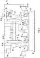
- a system may be utilized for the nondestructive evaluation (NDE) of railroad rails 12, 14.
- Rails 12, 14 each may have flat bottoms 16, 18, heads 20, 22 and webs 24, 26, respectively, joining the heads with the bottoms.
- the rails 12, 14 may be mounted on ties 28 (only one of which is shown in FIG. 1 ) that, in turn, may be mounted on ballast 30.
- the system 10 may include a carriage, generally designated 32, that may include a plurality of wheels, which may include wheels 36, 38 shown in FIG. 1 , and wheels 38, 40 in FIG. 2 .
- the wheels 36, 38 may be mounted on an axle 42 that may be attached to the carriage 32 by a truck 44 ( FIG. 2 ).
- a source of vibration 46 may be mounted on the carriage 32 and connected to transmit vibrations of a preselected frequency to test regions 48, 50 on the rails 12, 14 through the wheels 36, 38 to cause an increase in temperature of the rails at locations of flaws 52.
- the source of vibration 46 may take the form of an ultrasonic welder, such as an ultrasonic welder operating at a minimum of 400 watts.
- the frequency of the vibration may be selected from between 10 kHz and 40 kHz, dependent on the structure and material of the railroad rails 12, 14.
- the selected frequency may take the form of swept frequencies, for example vibrations at frequencies sweeping between 10 kHz and 40 kHz, which may be likely to cause a resonance in the railroad rails 12, 14.
- test regions 48, 50 for rail 14 are shown in FIG. 2 , it being understood that corresponding test regions, not shown, exist directly across on rail 12. Although two test regions 48, 50 are shown in FIG. 2 , test regions may be designated all along the lengths of rails 12, 14, and in embodiments adjacent test regions may be contiguous, as are test regions 48, 50 along the lengths of the rails 12, 14 under study.
- An infrared detector may be positioned to record thermal images of the test regions 48, 50 to detect the increase in temperature at the locations of the flaws 52 as a result of heat generated by the vibrations from the source of vibrations 46.
- a flaw 52 may take the form of a break in the surface of the rail 12.
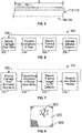
- a representative example of such a thermal image 300 is shown in FIG. 8 .
- the presence of a flaw 52 ( FIG. 1 ) may appear as a bright line 302 approximating the shape and location of the flaw in the rail 12 against a relatively dark or black background 304.
- the system 10 also may include a controller 56 connected to actuate the infrared detector 54 to record the thermal images of the vibrations impacting the test regions 48, 50, and store the thermal images recorded by the infrared detector.
- the infrared detector 54 may take the form of an array, generally designated 58, of infrared cameras 60, 62, 64, 66, 68, and 70 mounted on and movable with the railcar 32.
- infrared camera 60 is oriented to record an image of an outside web portion 72 of rail 14
- camera 62 is oriented to record an image of an upper surface of the head portion 22 of rail 14
- camera 64 is oriented to record an image of an inside web portion 74 of rail 14
- camera 66 is oriented to record an image of an inside web portion 76 of rail 12
- camera 68 is oriented to record a thermal image of the upper surface of the head portion 20 of rail 12
- camera 70 is oriented to record an image of an outside web portion 78 of rail 12.
- the cameras 60-70 may be mounted on the carriage 32 so that movement of the carriage relative to the rails 12, 14 also moves the camera 60-70 of the array 58.
- cameras 60, 64, 66, and 70 may be oriented to record images of the bottoms 16, 18 of the rails 12, 14 instead or in addition to imaging webs 24, 26 of the rails 12, 14.
- the carriage or railcar 32 may include an onboard motor 80 that may be actuated by the controller 56, or by an operator, to move the railcar in the direction of arrow A in FIG. 2 over the rails 12, 14 so that the array 58 of the infrared detector 54 passes over the test regions 48, 50.
- the carriage would not have a motor 80, but would rather be pushed or pulled by an outside motive force, such as a traction engine (not shown).
- the source of vibration 46 may take the form of an ultrasonic transducer 82 that contacts a component 84 of the carriage 32.
- the ultrasonic transducer 82 may be connected such that the controller 56 actuates the ultrasonic transducer to transmit the vibrations through the component 84 to the test regions 48, 50 of the rails 12, 14.
- the component 84 may be selected from the wheels 36, 38 and/or the axle 42 connected to the wheels and attached to a remainder of the carriage 32, which may be by way of truck 44.
- the source of vibration 46 may take the form of one or more of the plurality of wheels, for example wheels 36, 38, having peripheries 85, 86 sufficiently rough to cause the vibrations in the test regions 48, 50 of a preselected frequency when the railcar 32 moves relative to the rails 12, 14 at a preselected speed.
- the wheels 36, 38 may have peripheries 85, 86 that include transverse grooves or ridges spaced and shaped to create a vibration in excess of 1 kilohertz as the railcar 32 moves at a speed of 25 miles per hour over the rails 12, 14.
- This frequency may be selected to maximize the temperature increase at the flaw or flaws 52 in the rails 12, 14 so that the thermal images 300 captured by the infrared detector 54 will show bright spots 302 coinciding with the flaws 52 ( FIG. 8 ).
- the peripheries 85, 86 of the wheels 36, 38 may have segmented surfaces 88, 90.
- the wheels such as wheels 38, 40 (as well as corresponding wheels, of which wheel 36 is one, on an opposite side of railcar 32 that engage rail 12), may have peripheries 86, 92 with segmented surfaces arranged to generate the vibrations in the rails 12, 14 as the carriage 32 moves relative to the rails.
- the segmented surfaces of the peripheries 86, 92 may be oriented such that they are out of phase with each other, and the preselected frequency may be selected to be greater than 1 kilohertz (kHz).
- the controller 56 may include a data store 94 for storing the recorded thermal images by the infrared detector 54. Also in an embodiment, the controller 56 may include a visible light camera 96 connected to be actuated by the controller for photographing the test regions 48, 50, for purposed of determining false positives by the detector 54 and/or for identifying the rail test region 48, 50 containing the flaw 52. The controller may be programmed to actuate the visible light camera 96 only when a flaw 52 is detected in one of the rails 12, 14. The controller 56 also may include a global positioning system (GPS) 98 that may be connected to record a location of a flaw 52 in one or both of the rails 12, 14 detected by the infrared detector 54.
- GPS global positioning system
- a system, generally designated 100, for nondestructive evaluation of a wheel assembly, generally designated 102, on a railcar 104 may include a pair of rails 106, 108, each having an excitation segment 110, 112, which may include a source of vibration 114, 116 connected to transmit vibrations of a preselected frequency sequentially to test regions 118, 120 of wheel 138 and to test regions 122, 124 of wheel 140 on the wheel assembly 102 to cause an increase in temperature of the wheel assembly at locations of flaws 126, 128 in the test regions.
- the system 100 also may include an infrared detector 130 for recording thermal images 300 ( FIG. 8 ) of the test regions 118-124 to detect the increase in temperature at the locations of flaws 126, 128.
- the system 100 also may include a controller 132 connected to actuate the infrared detector 130 to record the thermal images 300 of the vibrations impacting the test regions 118-124, and store the thermal images recorded by the infrared detector.
- the system also may include a visible light camera 134 connected to be actuated by the controller 132 to record an image of the railcar 104 having the wheel assembly 102 for which thermal images are recorded.
- the railcar 104 may include a unique indicia 136, which may take the form of a barcode or other alphanumeric code, that may uniquely identify the railcar and may be located at a predetermined position on a side of the railcar.
- the visible light camera 134 may photograph the indicia 136 for purposes of identifying the railcar 104 as having a wheel assembly 102 with wheels 138, 140 having flaws 126, 128. As shown in FIG.
- the railcar 104 may include wheel assembly 102, which may take the form of wheels 138, 140 that may be mounted on a truck 142 on one side of the railcar, and similarly, wheels 144, 146 on an opposite side of the railcar 104, which may be mounted on a truck 148, and ride on rail 106.
- trucks 142 and 148 may take the form of a single truck on which wheels 138, 140, 144, and 146 are rotatably mounted, and which is rotatably mounted on railcar 104.
- the infrared detector 130 may take the form of an array, generally designated 150, of infrared cameras positioned to record thermal images of the outboard faces 152, 154, 156, 158 of wheels 138, 140, 146, 144, respectively, of the wheel assembly 102, and inboard faces 160, 162, 164, 166, of the wheels 144, 138, 140, 146, respectively, as the wheels pass over the excitation segments 110, 112 of the rails 106, 108.
- the array 150 of infrared cameras may be arranged along the lengths of the excitation segments 110, 112 sufficient to record images of entire circumferences of two sets of the wheels 138, 140 and 144, 146 on railroad trucks 142, 148, respectively.
- the array 150 may include infrared cameras 168, 170, 172, 174 positioned to record thermal images of the outboard faces 152, 154, 156, and 158 of wheels 138, 140, 144, 146.
- the array 150 may include infrared cameras 175, 176 positioned to take infrared images of the inboard surfaces 162, 164 of wheels 138, 140, respectively, and cameras 178, 180 positioned to take thermal images of the inboard surfaces 166, 160 of wheels 146, 144, respectively.
- the infrared detector 130 may include an array 150 of infrared cameras that may include cameras 168-180 positioned to record thermal images of the axles 182, 184 of the wheel assembly 102 as the axles pass over the excitation segments 110, 112.
- the system 100 may include a marker 186 that may be actuated by the controller 132.
- the marker may take the form of a dye marker, ink jet sprayer, or other device for depositing a substance on a selected wheel 138, 140 that may have a flaw 126, 128 that is detected by the system 100.
- the marker 186 may be positioned to deposit the marking substance on either one of the wheels 138, 140, for example, or on an axle, such as axles 182, 184.
- the infrared cameras 175, 176, 178, 180 may be positioned beneath the axles on ties and oriented to point upwardly so that they may take images of the axles from beneath.
- the source of vibration 114, 116 may take the form of an ultrasonic transducer or transducers connected to the rails 106, 108 to transmit vibrations to the excitation segments 110, 112 of the rails.
- the ultrasonic transducers 114, 116 may be connected to be actuated by the controller 132 to transmit the vibrations to the test regions 118, 120, 122, 124, for example, of the wheel assemblies 102 when the test regions contact the excitation segments.
- the controller 132 may be connected to be actuated by the controller 132 to transmit the vibrations to the test regions 118, 120, 122, 124, for example, of the wheel assemblies 102 when the test regions contact the excitation segments.
- the source of vibration may include the excitation segments 110', 112' having upper surfaces 190 with grooves 192 formed transversely therein and shaped such that movement of the wheels 138, 140, 144, 146 of the railcar 104 over the grooves at a predetermined speed causes the vibrations in the wheel assemblies 102 that create temperature increases at flaws 126, 128 that are imaged by the thermal images 300 ( FIG. 8 ) taken by the infrared detector 130.
- the excitation segments 110, 112 may have a length indicated in FIGS. 3 and 5 by the distance S . That distance S preferably is equal to ⁇ x (D + L) , where D is the diameter of the wheels 138, 140, 144, and 146 and L is the center-to-center spacing between wheels 138, 140 and between wheels 144,146 on the trucks 142, 148. With this minimum rail length S , both wheels 138, 140 and 144, 146 of each pair of wheels may be scanned and imaged by the infrared detector 130 as they roll around their entire circumferences.
- Energizing the system 100 for the full rotation of the wheels 138, 140, 144, and 146 increases the opportunity to detect a flaw, such as cracks 126, 128, especially if the weight of the railcar 104 or position of the wheels effected the thermal response to the excitation.
- the method begins by moving the carriage 32 having a plurality of wheels 36, 38, 40 over the rails 12, 14 in the direction of arrow A , as indicated in block 202.
- This movement of the carriage or railcar 32 brings the carriage over a selected one of the test regions 48, so that the infrared cameras 60-70 of the array 58 of the infrared detector 54 are in position to record thermal images 300 of the feet, webs and heads of the rails 12, 14 within the test regions 48 of those rails.
- vibrations are transmitted at a preselected frequency to the test regions 48, 50 on the rails 12, 14 through the wheels 36, 38, 40 by the source of vibration 46 mounted on the carriage 32.
- the source of vibration 46 may be an ultrasonic transducer 82, and/or contact with the rails 12, 14 by the segmented peripheries 85, 86, 92 of one or more of the wheels 36, 38, 40 (which, in embodiments, may have the appearance of grooves 192 of FIG. 5 ).
- the vibrations may cause an increase in temperature of the rails 12, 14 at locations of flaws 52 in the test region 48.
- the thermal images 300 may be recorded by an infrared detector, generally designated 54, in the test region 48 which detect and record the increase in temperature at the locations of the flaws 52. These increases in temperature appear as bright spots 302 on the thermal images 300 recorded by the infrared detector 54.
- the controller 56 may actuate the infrared detector 54 to record the thermal images 300 of the vibrations impacting the test regions 48, 50 and store the thermal images recorded by the infrared detector. These images may be reviewed later to make a determination on whether a repair is necessary.
- the images may be transmitted to a remote location and viewed on a display (not shown).
- the process 200 may be repeated by moving the carriage 32 in the direction of arrow A to the next contiguous test region 50 to repeat the process of blocks 204-208.
- block 212 indicates the initiation of the process by moving a carriage 104, which may take the form of a railcar, over the excitation segments 110, 112 of a pair of rails 106, 108, respectively, in the direction of arrow B .
- This motion moves the wheels 138, 140, 144, and 146 over the excitation segments 110, 112 so that the wheels are in position to be imaged by the infrared cameras 168-180 of the array 150 of infrared detector 130.
- vibrations may be transmitted at a preselected frequency by a source of vibrations 114, 116, or alternately, by ridges 192 ( FIG. 5 ), to the wheels 138, 140, 144, and 146 of wheel assemblies 102.
- the vibrations may be transmitted at test regions 118-124, which may be the portions of the wheels 138, 140, 144, and 146 that are in physical contact with the excitation segments 110, 112 of the rails 106, 108.
- an infrared detector 130 may be actuated to record thermal images 300 of the test regions 118-124 to detect the increase in temperature at the locations of the flaws 126, 128.
- a controller 132 may actuate the infrared detector 130 to record the thermal images 300 of the vibrations impacting the test regions and store the thermal images recorded by the infrared detector.
- the process 210 may be repeated by moving a subsequent railcar 104, or a subsequent wheel or wheel truck, over the excitation segments 110, 112 so that the wheels thereof are in position to be imaged by the infrared cameras 168-180.
- the system shown in FIGS. 1-5 may be used to detect flaws using a nondestructive evaluation process and system for rail vehicles and rail systems that may include railroads, trolleys, and other systems.
- the advantage of the systems 10, 100 and methods 200, 210 shown in the figures and described herein is that the testing may be done without removal of the tested components for remote testing, and may be performed on a kinetic reference frame; that is, a reference frame in which one of either the test object or the testing apparatus is moving relative to the other.
- a kinetic reference frame that is, a reference frame in which one of either the test object or the testing apparatus is moving relative to the other.
- the system 10 shown in FIGS. 1 and 2 it is the testing apparatus carried in carriage or railcar 32 that is moving relative to the stationary rails 12, 14 that are inspected.
- the test object is in the form of the wheels 138, 140, 144, and 146 of a railcar 104 that are moved past a stationary system 100 and the wheels and/or axles are imaged.
Landscapes
- Engineering & Computer Science (AREA)
- Physics & Mathematics (AREA)
- General Physics & Mathematics (AREA)
- Aviation & Aerospace Engineering (AREA)
- Mechanical Engineering (AREA)
- Analytical Chemistry (AREA)
- Life Sciences & Earth Sciences (AREA)
- Chemical & Material Sciences (AREA)
- Health & Medical Sciences (AREA)
- Biochemistry (AREA)
- General Health & Medical Sciences (AREA)
- Immunology (AREA)
- Pathology (AREA)
- Electromagnetism (AREA)
- Investigating Or Analyzing Materials Using Thermal Means (AREA)
- Radiation Pyrometers (AREA)
- Computer Vision & Pattern Recognition (AREA)
- Signal Processing (AREA)
Applications Claiming Priority (1)
| Application Number | Priority Date | Filing Date | Title |
|---|---|---|---|
| US15/265,509 US9752993B1 (en) | 2016-09-14 | 2016-09-14 | Nondestructive evaluation of railroad rails, wheels, and axles |
Publications (2)
| Publication Number | Publication Date |
|---|---|
| EP3296183A1 true EP3296183A1 (de) | 2018-03-21 |
| EP3296183B1 EP3296183B1 (de) | 2022-04-06 |
Family
ID=59350626
Family Applications (1)
| Application Number | Title | Priority Date | Filing Date |
|---|---|---|---|
| EP17178642.9A Active EP3296183B1 (de) | 2016-09-14 | 2017-06-29 | Zerstörungsfreie prüfung von eisenbahnschienen |
Country Status (4)
| Country | Link |
|---|---|
| US (1) | US9752993B1 (de) |
| EP (1) | EP3296183B1 (de) |
| JP (2) | JP6953240B2 (de) |
| CN (1) | CN107813848B (de) |
Families Citing this family (30)
| Publication number | Priority date | Publication date | Assignee | Title |
|---|---|---|---|---|
| US9849894B2 (en) | 2015-01-19 | 2017-12-26 | Tetra Tech, Inc. | Protective shroud for enveloping light from a light emitter for mapping of a railway track |
| US10349491B2 (en) | 2015-01-19 | 2019-07-09 | Tetra Tech, Inc. | Light emission power control apparatus and method |
| US9849895B2 (en) | 2015-01-19 | 2017-12-26 | Tetra Tech, Inc. | Sensor synchronization apparatus and method |
| CA2892885C (en) | 2015-02-20 | 2020-07-28 | Tetra Tech, Inc. | 3d track assessment system and method |
| US10458852B2 (en) * | 2016-03-29 | 2019-10-29 | Progress Rail Services Corporation | System and method for detecting temperature of railroad train wheel and bearing |
| US10191014B2 (en) * | 2016-08-23 | 2019-01-29 | The Boeing Company | System and method for nondestructive evaluation of a test object |
| WO2019055994A1 (en) * | 2017-09-18 | 2019-03-21 | Board Of Regents, The University Of Texas System | MOBILE DETECTION OF RAILWAY TRACK FAILURE |
| US20180194380A1 (en) * | 2018-01-09 | 2018-07-12 | Saleh Akbari | Method and system of railway track parameter measurement and calculation |
| US11994436B2 (en) * | 2018-04-30 | 2024-05-28 | University Of South Carolina | Non-contact methods of rail assessment for a railroad track |
| US10625760B2 (en) | 2018-06-01 | 2020-04-21 | Tetra Tech, Inc. | Apparatus and method for calculating wooden crosstie plate cut measurements and rail seat abrasion measurements based on rail head height |
| US10807623B2 (en) | 2018-06-01 | 2020-10-20 | Tetra Tech, Inc. | Apparatus and method for gathering data from sensors oriented at an oblique angle relative to a railway track |
| US11377130B2 (en) | 2018-06-01 | 2022-07-05 | Tetra Tech, Inc. | Autonomous track assessment system |
| US10730538B2 (en) | 2018-06-01 | 2020-08-04 | Tetra Tech, Inc. | Apparatus and method for calculating plate cut and rail seat abrasion based on measurements only of rail head elevation and crosstie surface elevation |
| US10710615B2 (en) * | 2018-06-05 | 2020-07-14 | The Boeing Company | In-motion high-speed non-destructive evaluation for railcar axles |
| US11002697B2 (en) * | 2018-08-17 | 2021-05-11 | The Boeing Company | Robotic infrared thermographic inspection for unitized composite structures |
| AU2019236641A1 (en) * | 2018-09-28 | 2020-04-16 | Ensco, Inc. | Systems and methods for analyzing thermal properties of a railroad |
| AU2020273465C1 (en) | 2019-05-16 | 2026-02-05 | Tetra Tech, Inc. | System and method for generating and interpreting point clouds of a rail corridor along a survey path |
| US11386545B2 (en) | 2020-03-31 | 2022-07-12 | The Boeing Company | Surface crack detection |
| TW202212793A (zh) * | 2020-05-08 | 2022-04-01 | 日商國際計測器股份有限公司 | 車輪測試裝置 |
| USD974215S1 (en) * | 2021-07-12 | 2023-01-03 | Liuyang Zhou | Watch case |
| CN114368408A (zh) * | 2021-11-18 | 2022-04-19 | 成都盛锴科技有限公司 | 一种在线式走行部异常温升检测系统 |
| CN114537466B (zh) * | 2022-02-25 | 2023-06-16 | 京沪高速铁路股份有限公司 | 高速铁路轨道结构变形损伤监测系统及方法 |
| CN114994052B (zh) * | 2022-05-23 | 2024-09-24 | 西南交通大学 | 一种基于长周期光纤光栅的钢轨腐蚀监测装置 |
| CN115180519B (zh) * | 2022-06-28 | 2024-07-09 | 厦门市特种设备检验检测院 | 一种防护性高的起重机械安全检测装置 |
| CN115287951A (zh) * | 2022-07-12 | 2022-11-04 | 长安大学 | 一种扣件弹条松动识别系统及方法 |
| CN116105889A (zh) * | 2022-12-15 | 2023-05-12 | 中铁第一勘察设计院集团有限公司 | 一种无缝线路锁定轨温的检测方法、装置以及检测小车 |
| KR102592635B1 (ko) * | 2023-08-04 | 2023-10-23 | 주식회사 워킹트리 | 철도차량의 차륜 및 하부장치 검사용 로봇 시스템 |
| CN117634989B (zh) * | 2024-01-25 | 2024-05-28 | 深圳市大力鸿震智能脚轮科技有限公司 | 一种基于人工智能的脚轮质量评估方法、系统及存储介质 |
| KR20250173213A (ko) | 2024-06-03 | 2025-12-10 | 유이소프트 주식회사 | 철도차량 차륜 자동검사시스템 |
| CN120681206B (zh) * | 2025-06-16 | 2025-11-14 | 北京福欣诚科技有限公司 | 一种用于高速轨道交通配套设备结构的安全检测系统 |
Citations (4)
| Publication number | Priority date | Publication date | Assignee | Title |
|---|---|---|---|---|
| US20040159790A1 (en) * | 2002-12-20 | 2004-08-19 | The Boeing Company | Translatable ultrasonic thermography inspection apparatus and method |
| US20090049936A1 (en) * | 2007-08-20 | 2009-02-26 | Mian Zahid F | Wayside rolling stock inspection |
| US20130220019A1 (en) * | 2012-02-28 | 2013-08-29 | Sperry Rail, Inc. | System and Method for Non-Destructive Testing of Railroad Rails Using Ultrasonic Apparatuses Mounted Within Fluid-Filled Tires Maintained at Constant Temperatures |
| US20140316719A1 (en) * | 2011-11-10 | 2014-10-23 | The Regents Of The University Of California | Stress detection in rail |
Family Cites Families (21)
| Publication number | Priority date | Publication date | Assignee | Title |
|---|---|---|---|---|
| US5149025A (en) * | 1988-10-11 | 1992-09-22 | Harmon Industries, Inc. | Detection of overheated railroad wheel and axle components |
| US4955236A (en) * | 1988-11-22 | 1990-09-11 | Nec Environment Engineering Ltd. | Method for observation of vibration mode |
| US5335995A (en) * | 1993-07-16 | 1994-08-09 | Servo Corporation Of America | Resilient support for a railroad wheel heat sensor |
| JPH08228401A (ja) * | 1995-02-22 | 1996-09-03 | Mitsubishi Heavy Ind Ltd | レール温度検知装置 |
| US5677533A (en) * | 1995-09-29 | 1997-10-14 | Science Applications International Corporation | Apparatus for detecting abnormally high temperature conditions in the wheels and bearings of moving railroad cars |
| US5870192A (en) | 1998-05-08 | 1999-02-09 | Barker; Lynn M. | Multibeam visar using image coupling from one optical fiber bundle to another through the visar interferometer |
| JP3492208B2 (ja) * | 1998-07-22 | 2004-02-03 | 東日本旅客鉄道株式会社 | 鉄道車両の床下機器監視装置 |
| JP2002541448A (ja) | 1999-04-01 | 2002-12-03 | シーメンス シュヴァイツ アクチエンゲゼルシャフト | 多軸車両のボギー台車を監視する方法と装置 |
| EP1214575B1 (de) | 1999-09-16 | 2004-12-22 | Wayne State University | Miniaturisiertes berührungsloses schall-/infrarotgerät zur zerstörungsfreien abstandsprüfung |
| US7064330B2 (en) * | 2003-04-30 | 2006-06-20 | United Technologies Corporation | Infrared defect detection via broad-band acoustics |
| JP4065831B2 (ja) * | 2003-11-28 | 2008-03-26 | 財団法人鉄道総合技術研究所 | クリープ力測定装置及び方法 |
| US8958079B2 (en) * | 2004-06-30 | 2015-02-17 | Georgetown Rail Equipment Company | System and method for inspecting railroad ties |
| US7295321B1 (en) | 2004-11-30 | 2007-11-13 | National Security Technologies, Llc | VISAR interferometer with field elements |
| JP4803652B2 (ja) * | 2005-12-16 | 2011-10-26 | Jfeスチール株式会社 | 構造物の欠陥検出方法および装置 |
| JP4898320B2 (ja) | 2006-06-28 | 2012-03-14 | Jfeスチール株式会社 | 構造物の欠陥検出方法および装置、ならびに欠陥検出機能を備えた荷役機械 |
| JP2011214986A (ja) * | 2010-03-31 | 2011-10-27 | Jfe Steel Corp | レール探傷装置 |
| CN101893580B (zh) * | 2010-06-10 | 2012-01-11 | 北京交通大学 | 基于数字图像的钢轨表面缺陷检测方法 |
| JP2012107919A (ja) | 2010-11-16 | 2012-06-07 | Hanshin Expressway Co Ltd | 鋼床版検査装置 |
| US8806950B2 (en) | 2011-11-09 | 2014-08-19 | The Boeing Company | Electromagnetic acoustic transducer system |
| CN103847761B (zh) * | 2012-11-30 | 2016-06-29 | 建维科技(深圳)有限公司 | 一种用于实时监测铁轨裂缝及损伤的系统及方法 |
| CN104960546A (zh) * | 2015-07-16 | 2015-10-07 | 无锡市崇安区科技创业服务中心 | 一种用于巡检高铁钢轨的探伤车 |
-
2016
- 2016-09-14 US US15/265,509 patent/US9752993B1/en active Active
-
2017
- 2017-06-29 EP EP17178642.9A patent/EP3296183B1/de active Active
- 2017-08-04 CN CN201710659238.9A patent/CN107813848B/zh active Active
- 2017-09-05 JP JP2017169999A patent/JP6953240B2/ja active Active
-
2021
- 2021-09-29 JP JP2021159561A patent/JP7161015B2/ja active Active
Patent Citations (4)
| Publication number | Priority date | Publication date | Assignee | Title |
|---|---|---|---|---|
| US20040159790A1 (en) * | 2002-12-20 | 2004-08-19 | The Boeing Company | Translatable ultrasonic thermography inspection apparatus and method |
| US20090049936A1 (en) * | 2007-08-20 | 2009-02-26 | Mian Zahid F | Wayside rolling stock inspection |
| US20140316719A1 (en) * | 2011-11-10 | 2014-10-23 | The Regents Of The University Of California | Stress detection in rail |
| US20130220019A1 (en) * | 2012-02-28 | 2013-08-29 | Sperry Rail, Inc. | System and Method for Non-Destructive Testing of Railroad Rails Using Ultrasonic Apparatuses Mounted Within Fluid-Filled Tires Maintained at Constant Temperatures |
Also Published As
| Publication number | Publication date |
|---|---|
| JP2018054604A (ja) | 2018-04-05 |
| US9752993B1 (en) | 2017-09-05 |
| JP6953240B2 (ja) | 2021-10-27 |
| CN107813848A (zh) | 2018-03-20 |
| EP3296183B1 (de) | 2022-04-06 |
| JP2022000655A (ja) | 2022-01-04 |
| JP7161015B2 (ja) | 2022-10-25 |
| CN107813848B (zh) | 2021-04-02 |
Similar Documents
| Publication | Publication Date | Title |
|---|---|---|
| US9752993B1 (en) | Nondestructive evaluation of railroad rails, wheels, and axles | |
| Falamarzi et al. | A review on existing sensors and devices for inspecting railway infrastructure | |
| CN107764862B (zh) | 用于测试对象的无损评估的系统和方法 | |
| US7882742B1 (en) | Apparatus for detecting, identifying and recording the location of defects in a railway rail | |
| US6055862A (en) | Method of and an apparatus for detecting, identifying and recording the location of defects in a railway rail | |
| CN102548828B (zh) | 用于检测铁轨缺陷,特别是铁轨顶部缺陷的方法和设备 | |
| Li et al. | Rail inspection meets big data: Methods and trends | |
| AU647649B2 (en) | Method and system for nondestructive testing of railroad crossties | |
| EP3578962B1 (de) | Zerstörungsfreie auswertung während der bewegung für schienenfahrzeugachsen bei hoher geschwindigkeit | |
| AU2018213965A1 (en) | Method and system for non-destructive rail inspection | |
| WO2000002757A1 (en) | Method and apparatus for detecting defective track wheels | |
| WO2019185873A1 (en) | System and method for detecting and associating railway related data | |
| Rizzo | Sensing solutions for assessing and monitoring railroad tracks | |
| JPH10307015A (ja) | 走行レールの検査方法および装置 | |
| RU2744644C1 (ru) | Автоматизированный комплекс неразрушающего контроля колёсных пар вагонов | |
| KR101608424B1 (ko) | 철도시스템 유지보수 효율화를 위한 검사 장치 | |
| RU2652673C1 (ru) | Способ определения стрелочных переводов и положения остряков | |
| Shah et al. | Development of a wireless track recording vehicle with a low environmental impact: An approach for enhancing railway track safety standards | |
| Chetty et al. | A comprehensive review on rail wheel crack inspection system | |
| RU2642687C1 (ru) | Способ комплексной диагностики рельсов | |
| RU2742368C1 (ru) | Ручной сканер для неразрушающего контроля поверхности катания и прилегающих к ней зон колес рельсового транспорта | |
| RU201533U1 (ru) | Ручной сканер для неразрушающего контроля галтельного перехода и поверхности диска колес рельсового транспорта | |
| Nielsen et al. | Automatic laser ultrasonics for rail inspection | |
| RU201551U1 (ru) | Ручной сканер для неразрушающего контроля кромки ступицы и прилегающих к ней галтельных переходов колес рельсового транспорта | |
| JPH05164534A (ja) | 鉄道レールの疲労損傷評価装置とその評価方法 |
Legal Events
| Date | Code | Title | Description |
|---|---|---|---|
| PUAI | Public reference made under article 153(3) epc to a published international application that has entered the european phase |
Free format text: ORIGINAL CODE: 0009012 |
|
| STAA | Information on the status of an ep patent application or granted ep patent |
Free format text: STATUS: REQUEST FOR EXAMINATION WAS MADE |
|
| 17P | Request for examination filed |
Effective date: 20170629 |
|
| AK | Designated contracting states |
Kind code of ref document: A1 Designated state(s): AL AT BE BG CH CY CZ DE DK EE ES FI FR GB GR HR HU IE IS IT LI LT LU LV MC MK MT NL NO PL PT RO RS SE SI SK SM TR |
|
| AX | Request for extension of the european patent |
Extension state: BA ME |
|
| STAA | Information on the status of an ep patent application or granted ep patent |
Free format text: STATUS: EXAMINATION IS IN PROGRESS |
|
| 17Q | First examination report despatched |
Effective date: 20200317 |
|
| GRAP | Despatch of communication of intention to grant a patent |
Free format text: ORIGINAL CODE: EPIDOSNIGR1 |
|
| STAA | Information on the status of an ep patent application or granted ep patent |
Free format text: STATUS: GRANT OF PATENT IS INTENDED |
|
| INTG | Intention to grant announced |
Effective date: 20211015 |
|
| GRAS | Grant fee paid |
Free format text: ORIGINAL CODE: EPIDOSNIGR3 |
|
| GRAA | (expected) grant |
Free format text: ORIGINAL CODE: 0009210 |
|
| STAA | Information on the status of an ep patent application or granted ep patent |
Free format text: STATUS: THE PATENT HAS BEEN GRANTED |
|
| AK | Designated contracting states |
Kind code of ref document: B1 Designated state(s): AL AT BE BG CH CY CZ DE DK EE ES FI FR GB GR HR HU IE IS IT LI LT LU LV MC MK MT NL NO PL PT RO RS SE SI SK SM TR |
|
| REG | Reference to a national code |
Ref country code: GB Ref legal event code: FG4D |
|
| REG | Reference to a national code |
Ref country code: CH Ref legal event code: EP |
|
| REG | Reference to a national code |
Ref country code: AT Ref legal event code: REF Ref document number: 1481086 Country of ref document: AT Kind code of ref document: T Effective date: 20220415 |
|
| REG | Reference to a national code |
Ref country code: DE Ref legal event code: R096 Ref document number: 602017055454 Country of ref document: DE |
|
| REG | Reference to a national code |
Ref country code: IE Ref legal event code: FG4D |
|
| REG | Reference to a national code |
Ref country code: LT Ref legal event code: MG9D |
|
| REG | Reference to a national code |
Ref country code: NL Ref legal event code: MP Effective date: 20220406 |
|
| REG | Reference to a national code |
Ref country code: AT Ref legal event code: MK05 Ref document number: 1481086 Country of ref document: AT Kind code of ref document: T Effective date: 20220406 |
|
| PG25 | Lapsed in a contracting state [announced via postgrant information from national office to epo] |
Ref country code: NL Free format text: LAPSE BECAUSE OF FAILURE TO SUBMIT A TRANSLATION OF THE DESCRIPTION OR TO PAY THE FEE WITHIN THE PRESCRIBED TIME-LIMIT Effective date: 20220406 |
|
| PG25 | Lapsed in a contracting state [announced via postgrant information from national office to epo] |
Ref country code: SE Free format text: LAPSE BECAUSE OF FAILURE TO SUBMIT A TRANSLATION OF THE DESCRIPTION OR TO PAY THE FEE WITHIN THE PRESCRIBED TIME-LIMIT Effective date: 20220406 Ref country code: PT Free format text: LAPSE BECAUSE OF FAILURE TO SUBMIT A TRANSLATION OF THE DESCRIPTION OR TO PAY THE FEE WITHIN THE PRESCRIBED TIME-LIMIT Effective date: 20220808 Ref country code: NO Free format text: LAPSE BECAUSE OF FAILURE TO SUBMIT A TRANSLATION OF THE DESCRIPTION OR TO PAY THE FEE WITHIN THE PRESCRIBED TIME-LIMIT Effective date: 20220706 Ref country code: LT Free format text: LAPSE BECAUSE OF FAILURE TO SUBMIT A TRANSLATION OF THE DESCRIPTION OR TO PAY THE FEE WITHIN THE PRESCRIBED TIME-LIMIT Effective date: 20220406 Ref country code: HR Free format text: LAPSE BECAUSE OF FAILURE TO SUBMIT A TRANSLATION OF THE DESCRIPTION OR TO PAY THE FEE WITHIN THE PRESCRIBED TIME-LIMIT Effective date: 20220406 Ref country code: GR Free format text: LAPSE BECAUSE OF FAILURE TO SUBMIT A TRANSLATION OF THE DESCRIPTION OR TO PAY THE FEE WITHIN THE PRESCRIBED TIME-LIMIT Effective date: 20220707 Ref country code: FI Free format text: LAPSE BECAUSE OF FAILURE TO SUBMIT A TRANSLATION OF THE DESCRIPTION OR TO PAY THE FEE WITHIN THE PRESCRIBED TIME-LIMIT Effective date: 20220406 Ref country code: ES Free format text: LAPSE BECAUSE OF FAILURE TO SUBMIT A TRANSLATION OF THE DESCRIPTION OR TO PAY THE FEE WITHIN THE PRESCRIBED TIME-LIMIT Effective date: 20220406 Ref country code: BG Free format text: LAPSE BECAUSE OF FAILURE TO SUBMIT A TRANSLATION OF THE DESCRIPTION OR TO PAY THE FEE WITHIN THE PRESCRIBED TIME-LIMIT Effective date: 20220706 Ref country code: AT Free format text: LAPSE BECAUSE OF FAILURE TO SUBMIT A TRANSLATION OF THE DESCRIPTION OR TO PAY THE FEE WITHIN THE PRESCRIBED TIME-LIMIT Effective date: 20220406 |
|
| PG25 | Lapsed in a contracting state [announced via postgrant information from national office to epo] |
Ref country code: RS Free format text: LAPSE BECAUSE OF FAILURE TO SUBMIT A TRANSLATION OF THE DESCRIPTION OR TO PAY THE FEE WITHIN THE PRESCRIBED TIME-LIMIT Effective date: 20220406 Ref country code: PL Free format text: LAPSE BECAUSE OF FAILURE TO SUBMIT A TRANSLATION OF THE DESCRIPTION OR TO PAY THE FEE WITHIN THE PRESCRIBED TIME-LIMIT Effective date: 20220406 Ref country code: LV Free format text: LAPSE BECAUSE OF FAILURE TO SUBMIT A TRANSLATION OF THE DESCRIPTION OR TO PAY THE FEE WITHIN THE PRESCRIBED TIME-LIMIT Effective date: 20220406 Ref country code: IS Free format text: LAPSE BECAUSE OF FAILURE TO SUBMIT A TRANSLATION OF THE DESCRIPTION OR TO PAY THE FEE WITHIN THE PRESCRIBED TIME-LIMIT Effective date: 20220806 |
|
| REG | Reference to a national code |
Ref country code: DE Ref legal event code: R097 Ref document number: 602017055454 Country of ref document: DE |
|
| PG25 | Lapsed in a contracting state [announced via postgrant information from national office to epo] |
Ref country code: SM Free format text: LAPSE BECAUSE OF FAILURE TO SUBMIT A TRANSLATION OF THE DESCRIPTION OR TO PAY THE FEE WITHIN THE PRESCRIBED TIME-LIMIT Effective date: 20220406 Ref country code: SK Free format text: LAPSE BECAUSE OF FAILURE TO SUBMIT A TRANSLATION OF THE DESCRIPTION OR TO PAY THE FEE WITHIN THE PRESCRIBED TIME-LIMIT Effective date: 20220406 Ref country code: RO Free format text: LAPSE BECAUSE OF FAILURE TO SUBMIT A TRANSLATION OF THE DESCRIPTION OR TO PAY THE FEE WITHIN THE PRESCRIBED TIME-LIMIT Effective date: 20220406 Ref country code: MC Free format text: LAPSE BECAUSE OF FAILURE TO SUBMIT A TRANSLATION OF THE DESCRIPTION OR TO PAY THE FEE WITHIN THE PRESCRIBED TIME-LIMIT Effective date: 20220406 Ref country code: EE Free format text: LAPSE BECAUSE OF FAILURE TO SUBMIT A TRANSLATION OF THE DESCRIPTION OR TO PAY THE FEE WITHIN THE PRESCRIBED TIME-LIMIT Effective date: 20220406 Ref country code: DK Free format text: LAPSE BECAUSE OF FAILURE TO SUBMIT A TRANSLATION OF THE DESCRIPTION OR TO PAY THE FEE WITHIN THE PRESCRIBED TIME-LIMIT Effective date: 20220406 Ref country code: CZ Free format text: LAPSE BECAUSE OF FAILURE TO SUBMIT A TRANSLATION OF THE DESCRIPTION OR TO PAY THE FEE WITHIN THE PRESCRIBED TIME-LIMIT Effective date: 20220406 |
|
| REG | Reference to a national code |
Ref country code: CH Ref legal event code: PL |
|
| PLBE | No opposition filed within time limit |
Free format text: ORIGINAL CODE: 0009261 |
|
| STAA | Information on the status of an ep patent application or granted ep patent |
Free format text: STATUS: NO OPPOSITION FILED WITHIN TIME LIMIT |
|
| REG | Reference to a national code |
Ref country code: BE Ref legal event code: MM Effective date: 20220630 |
|
| 26N | No opposition filed |
Effective date: 20230110 |
|
| PG25 | Lapsed in a contracting state [announced via postgrant information from national office to epo] |
Ref country code: AL Free format text: LAPSE BECAUSE OF FAILURE TO SUBMIT A TRANSLATION OF THE DESCRIPTION OR TO PAY THE FEE WITHIN THE PRESCRIBED TIME-LIMIT Effective date: 20220406 |
|
| PG25 | Lapsed in a contracting state [announced via postgrant information from national office to epo] |
Ref country code: LU Free format text: LAPSE BECAUSE OF NON-PAYMENT OF DUE FEES Effective date: 20220629 Ref country code: LI Free format text: LAPSE BECAUSE OF NON-PAYMENT OF DUE FEES Effective date: 20220630 Ref country code: IE Free format text: LAPSE BECAUSE OF NON-PAYMENT OF DUE FEES Effective date: 20220629 Ref country code: CH Free format text: LAPSE BECAUSE OF NON-PAYMENT OF DUE FEES Effective date: 20220630 |
|
| PG25 | Lapsed in a contracting state [announced via postgrant information from national office to epo] |
Ref country code: SI Free format text: LAPSE BECAUSE OF FAILURE TO SUBMIT A TRANSLATION OF THE DESCRIPTION OR TO PAY THE FEE WITHIN THE PRESCRIBED TIME-LIMIT Effective date: 20220406 Ref country code: BE Free format text: LAPSE BECAUSE OF NON-PAYMENT OF DUE FEES Effective date: 20220630 |
|
| P01 | Opt-out of the competence of the unified patent court (upc) registered |
Effective date: 20230516 |
|
| PG25 | Lapsed in a contracting state [announced via postgrant information from national office to epo] |
Ref country code: IT Free format text: LAPSE BECAUSE OF FAILURE TO SUBMIT A TRANSLATION OF THE DESCRIPTION OR TO PAY THE FEE WITHIN THE PRESCRIBED TIME-LIMIT Effective date: 20220406 |
|
| PG25 | Lapsed in a contracting state [announced via postgrant information from national office to epo] |
Ref country code: HU Free format text: LAPSE BECAUSE OF FAILURE TO SUBMIT A TRANSLATION OF THE DESCRIPTION OR TO PAY THE FEE WITHIN THE PRESCRIBED TIME-LIMIT; INVALID AB INITIO Effective date: 20170629 |
|
| PG25 | Lapsed in a contracting state [announced via postgrant information from national office to epo] |
Ref country code: MK Free format text: LAPSE BECAUSE OF FAILURE TO SUBMIT A TRANSLATION OF THE DESCRIPTION OR TO PAY THE FEE WITHIN THE PRESCRIBED TIME-LIMIT Effective date: 20220406 Ref country code: CY Free format text: LAPSE BECAUSE OF FAILURE TO SUBMIT A TRANSLATION OF THE DESCRIPTION OR TO PAY THE FEE WITHIN THE PRESCRIBED TIME-LIMIT Effective date: 20220406 |
|
| PG25 | Lapsed in a contracting state [announced via postgrant information from national office to epo] |
Ref country code: TR Free format text: LAPSE BECAUSE OF FAILURE TO SUBMIT A TRANSLATION OF THE DESCRIPTION OR TO PAY THE FEE WITHIN THE PRESCRIBED TIME-LIMIT Effective date: 20220406 |
|
| PG25 | Lapsed in a contracting state [announced via postgrant information from national office to epo] |
Ref country code: MT Free format text: LAPSE BECAUSE OF FAILURE TO SUBMIT A TRANSLATION OF THE DESCRIPTION OR TO PAY THE FEE WITHIN THE PRESCRIBED TIME-LIMIT Effective date: 20220406 |
|
| PG25 | Lapsed in a contracting state [announced via postgrant information from national office to epo] |
Ref country code: BG Free format text: LAPSE BECAUSE OF FAILURE TO SUBMIT A TRANSLATION OF THE DESCRIPTION OR TO PAY THE FEE WITHIN THE PRESCRIBED TIME-LIMIT Effective date: 20220406 |
|
| PG25 | Lapsed in a contracting state [announced via postgrant information from national office to epo] |
Ref country code: BG Free format text: LAPSE BECAUSE OF FAILURE TO SUBMIT A TRANSLATION OF THE DESCRIPTION OR TO PAY THE FEE WITHIN THE PRESCRIBED TIME-LIMIT Effective date: 20220406 |
|
| PGFP | Annual fee paid to national office [announced via postgrant information from national office to epo] |
Ref country code: DE Payment date: 20250627 Year of fee payment: 9 |
|
| PGFP | Annual fee paid to national office [announced via postgrant information from national office to epo] |
Ref country code: GB Payment date: 20250627 Year of fee payment: 9 |
|
| PGFP | Annual fee paid to national office [announced via postgrant information from national office to epo] |
Ref country code: FR Payment date: 20250625 Year of fee payment: 9 |