EP3296162B1 - Gas generator, method for the production thereof and module having a gas generator - Google Patents
Gas generator, method for the production thereof and module having a gas generator Download PDFInfo
- Publication number
- EP3296162B1 EP3296162B1 EP17198738.1A EP17198738A EP3296162B1 EP 3296162 B1 EP3296162 B1 EP 3296162B1 EP 17198738 A EP17198738 A EP 17198738A EP 3296162 B1 EP3296162 B1 EP 3296162B1
- Authority
- EP
- European Patent Office
- Prior art keywords
- gas generator
- sealant
- plastic
- esp
- base
- Prior art date
- Legal status (The legal status is an assumption and is not a legal conclusion. Google has not performed a legal analysis and makes no representation as to the accuracy of the status listed.)
- Active
Links
- 238000004519 manufacturing process Methods 0.000 title description 5
- 238000000034 method Methods 0.000 title description 3
- 239000004033 plastic Substances 0.000 claims description 45
- 239000000565 sealant Substances 0.000 claims description 43
- 239000002184 metal Substances 0.000 claims description 19
- 239000000463 material Substances 0.000 claims description 18
- 239000007788 liquid Substances 0.000 claims description 9
- 230000007704 transition Effects 0.000 claims description 9
- 239000000853 adhesive Substances 0.000 claims description 7
- 230000001070 adhesive effect Effects 0.000 claims description 7
- 238000010521 absorption reaction Methods 0.000 claims description 3
- 230000009477 glass transition Effects 0.000 claims description 3
- XLYOFNOQVPJJNP-UHFFFAOYSA-N water Substances O XLYOFNOQVPJJNP-UHFFFAOYSA-N 0.000 claims description 3
- 238000000465 moulding Methods 0.000 claims 1
- 239000007789 gas Substances 0.000 description 92
- 238000002485 combustion reaction Methods 0.000 description 14
- 239000002313 adhesive film Substances 0.000 description 10
- 238000007789 sealing Methods 0.000 description 10
- 230000002093 peripheral effect Effects 0.000 description 9
- 230000007613 environmental effect Effects 0.000 description 7
- 238000007373 indentation Methods 0.000 description 7
- 230000004913 activation Effects 0.000 description 6
- 239000002985 plastic film Substances 0.000 description 6
- 229920006255 plastic film Polymers 0.000 description 6
- 239000012790 adhesive layer Substances 0.000 description 5
- 239000007850 fluorescent dye Substances 0.000 description 5
- 238000001746 injection moulding Methods 0.000 description 5
- 238000005538 encapsulation Methods 0.000 description 4
- 238000009434 installation Methods 0.000 description 4
- 230000001681 protective effect Effects 0.000 description 4
- 239000011324 bead Substances 0.000 description 3
- 239000000975 dye Substances 0.000 description 3
- 229910000831 Steel Inorganic materials 0.000 description 2
- 238000006073 displacement reaction Methods 0.000 description 2
- 239000000446 fuel Substances 0.000 description 2
- 239000003365 glass fiber Substances 0.000 description 2
- 238000002347 injection Methods 0.000 description 2
- 239000007924 injection Substances 0.000 description 2
- 239000010410 layer Substances 0.000 description 2
- 238000005507 spraying Methods 0.000 description 2
- 239000010959 steel Substances 0.000 description 2
- 238000003466 welding Methods 0.000 description 2
- 238000009736 wetting Methods 0.000 description 2
- NIXOWILDQLNWCW-UHFFFAOYSA-M Acrylate Chemical compound [O-]C(=O)C=C NIXOWILDQLNWCW-UHFFFAOYSA-M 0.000 description 1
- 150000001252 acrylic acid derivatives Chemical class 0.000 description 1
- 230000009471 action Effects 0.000 description 1
- 238000006243 chemical reaction Methods 0.000 description 1
- 230000000295 complement effect Effects 0.000 description 1
- 238000010276 construction Methods 0.000 description 1
- 238000005260 corrosion Methods 0.000 description 1
- 230000007797 corrosion Effects 0.000 description 1
- 239000000945 filler Substances 0.000 description 1
- 238000010438 heat treatment Methods 0.000 description 1
- 239000005001 laminate film Substances 0.000 description 1
- 230000014759 maintenance of location Effects 0.000 description 1
- 239000002991 molded plastic Substances 0.000 description 1
- 239000002245 particle Substances 0.000 description 1
- 238000005192 partition Methods 0.000 description 1
- 235000011837 pasties Nutrition 0.000 description 1
- 230000035515 penetration Effects 0.000 description 1
- 230000000704 physical effect Effects 0.000 description 1
- 238000003825 pressing Methods 0.000 description 1
- 230000008569 process Effects 0.000 description 1
- 239000003380 propellant Substances 0.000 description 1
- 210000003660 reticulum Anatomy 0.000 description 1
- 238000007493 shaping process Methods 0.000 description 1
- 239000007787 solid Substances 0.000 description 1
- 238000007711 solidification Methods 0.000 description 1
- 230000008023 solidification Effects 0.000 description 1
- 239000010421 standard material Substances 0.000 description 1
- 239000000126 substance Substances 0.000 description 1
- 239000002344 surface layer Substances 0.000 description 1
- 229920002725 thermoplastic elastomer Polymers 0.000 description 1
- 238000011144 upstream manufacturing Methods 0.000 description 1
Images

Classifications
-
- F—MECHANICAL ENGINEERING; LIGHTING; HEATING; WEAPONS; BLASTING
- F42—AMMUNITION; BLASTING
- F42B—EXPLOSIVE CHARGES, e.g. FOR BLASTING, FIREWORKS, AMMUNITION
- F42B3/00—Blasting cartridges, i.e. case and explosive
- F42B3/04—Blasting cartridges, i.e. case and explosive for producing gas under pressure
-
- B—PERFORMING OPERATIONS; TRANSPORTING
- B60—VEHICLES IN GENERAL
- B60R—VEHICLES, VEHICLE FITTINGS, OR VEHICLE PARTS, NOT OTHERWISE PROVIDED FOR
- B60R21/00—Arrangements or fittings on vehicles for protecting or preventing injuries to occupants or pedestrians in case of accidents or other traffic risks
- B60R21/02—Occupant safety arrangements or fittings, e.g. crash pads
- B60R21/16—Inflatable occupant restraints or confinements designed to inflate upon impact or impending impact, e.g. air bags
- B60R21/26—Inflatable occupant restraints or confinements designed to inflate upon impact or impending impact, e.g. air bags characterised by the inflation fluid source or means to control inflation fluid flow
- B60R21/264—Inflatable occupant restraints or confinements designed to inflate upon impact or impending impact, e.g. air bags characterised by the inflation fluid source or means to control inflation fluid flow using instantaneous generation of gas, e.g. pyrotechnic
-
- B—PERFORMING OPERATIONS; TRANSPORTING
- B01—PHYSICAL OR CHEMICAL PROCESSES OR APPARATUS IN GENERAL
- B01D—SEPARATION
- B01D39/00—Filtering material for liquid or gaseous fluids
- B01D39/10—Filter screens essentially made of metal
- B01D39/12—Filter screens essentially made of metal of wire gauze; of knitted wire; of expanded metal
-
- B—PERFORMING OPERATIONS; TRANSPORTING
- B60—VEHICLES IN GENERAL
- B60R—VEHICLES, VEHICLE FITTINGS, OR VEHICLE PARTS, NOT OTHERWISE PROVIDED FOR
- B60R21/00—Arrangements or fittings on vehicles for protecting or preventing injuries to occupants or pedestrians in case of accidents or other traffic risks
- B60R21/02—Occupant safety arrangements or fittings, e.g. crash pads
- B60R21/16—Inflatable occupant restraints or confinements designed to inflate upon impact or impending impact, e.g. air bags
- B60R21/20—Arrangements for storing inflatable members in their non-use or deflated condition; Arrangement or mounting of air bag modules or components
-
- B—PERFORMING OPERATIONS; TRANSPORTING
- B60—VEHICLES IN GENERAL
- B60R—VEHICLES, VEHICLE FITTINGS, OR VEHICLE PARTS, NOT OTHERWISE PROVIDED FOR
- B60R21/00—Arrangements or fittings on vehicles for protecting or preventing injuries to occupants or pedestrians in case of accidents or other traffic risks
- B60R21/02—Occupant safety arrangements or fittings, e.g. crash pads
- B60R21/16—Inflatable occupant restraints or confinements designed to inflate upon impact or impending impact, e.g. air bags
- B60R21/26—Inflatable occupant restraints or confinements designed to inflate upon impact or impending impact, e.g. air bags characterised by the inflation fluid source or means to control inflation fluid flow
- B60R21/264—Inflatable occupant restraints or confinements designed to inflate upon impact or impending impact, e.g. air bags characterised by the inflation fluid source or means to control inflation fluid flow using instantaneous generation of gas, e.g. pyrotechnic
- B60R21/2644—Inflatable occupant restraints or confinements designed to inflate upon impact or impending impact, e.g. air bags characterised by the inflation fluid source or means to control inflation fluid flow using instantaneous generation of gas, e.g. pyrotechnic using only solid reacting substances, e.g. pellets, powder
-
- B—PERFORMING OPERATIONS; TRANSPORTING
- B60—VEHICLES IN GENERAL
- B60R—VEHICLES, VEHICLE FITTINGS, OR VEHICLE PARTS, NOT OTHERWISE PROVIDED FOR
- B60R21/00—Arrangements or fittings on vehicles for protecting or preventing injuries to occupants or pedestrians in case of accidents or other traffic risks
- B60R21/02—Occupant safety arrangements or fittings, e.g. crash pads
- B60R21/16—Inflatable occupant restraints or confinements designed to inflate upon impact or impending impact, e.g. air bags
- B60R21/26—Inflatable occupant restraints or confinements designed to inflate upon impact or impending impact, e.g. air bags characterised by the inflation fluid source or means to control inflation fluid flow
- B60R21/268—Inflatable occupant restraints or confinements designed to inflate upon impact or impending impact, e.g. air bags characterised by the inflation fluid source or means to control inflation fluid flow using instantaneous release of stored pressurised gas
- B60R21/272—Inflatable occupant restraints or confinements designed to inflate upon impact or impending impact, e.g. air bags characterised by the inflation fluid source or means to control inflation fluid flow using instantaneous release of stored pressurised gas with means for increasing the pressure of the gas just before or during liberation, e.g. hybrid inflators
-
- B—PERFORMING OPERATIONS; TRANSPORTING
- B01—PHYSICAL OR CHEMICAL PROCESSES OR APPARATUS IN GENERAL
- B01D—SEPARATION
- B01D2279/00—Filters adapted for separating dispersed particles from gases or vapours specially modified for specific uses
- B01D2279/10—Filters adapted for separating dispersed particles from gases or vapours specially modified for specific uses for air bags, e.g. inflators therefor
-
- B—PERFORMING OPERATIONS; TRANSPORTING
- B60—VEHICLES IN GENERAL
- B60R—VEHICLES, VEHICLE FITTINGS, OR VEHICLE PARTS, NOT OTHERWISE PROVIDED FOR
- B60R21/00—Arrangements or fittings on vehicles for protecting or preventing injuries to occupants or pedestrians in case of accidents or other traffic risks
- B60R21/02—Occupant safety arrangements or fittings, e.g. crash pads
- B60R21/16—Inflatable occupant restraints or confinements designed to inflate upon impact or impending impact, e.g. air bags
- B60R21/26—Inflatable occupant restraints or confinements designed to inflate upon impact or impending impact, e.g. air bags characterised by the inflation fluid source or means to control inflation fluid flow
- B60R2021/26029—Ignitors
-
- B—PERFORMING OPERATIONS; TRANSPORTING
- B60—VEHICLES IN GENERAL
- B60R—VEHICLES, VEHICLE FITTINGS, OR VEHICLE PARTS, NOT OTHERWISE PROVIDED FOR
- B60R21/00—Arrangements or fittings on vehicles for protecting or preventing injuries to occupants or pedestrians in case of accidents or other traffic risks
- B60R21/02—Occupant safety arrangements or fittings, e.g. crash pads
- B60R21/16—Inflatable occupant restraints or confinements designed to inflate upon impact or impending impact, e.g. air bags
- B60R21/26—Inflatable occupant restraints or confinements designed to inflate upon impact or impending impact, e.g. air bags characterised by the inflation fluid source or means to control inflation fluid flow
- B60R2021/26076—Inflatable occupant restraints or confinements designed to inflate upon impact or impending impact, e.g. air bags characterised by the inflation fluid source or means to control inflation fluid flow characterised by casing
Definitions
- the invention relates to a gas generator according to the preamble of claim 1.
- Gas generators for protective devices in a vehicle drive e.g. Parts (putting on bonnets, straightening the belt, moving upholstery or the like) or inflate airbags.
- the invention improves such a known construction in terms of additional protection of the gas generator against external environmental influences, further regarding a possibility of electrically non-conductive execution of a portion of an outer casing of the gas generator and further in terms of increasing flexibility in the manufacture of the gas generator by the characterizing feature of claim 1 ,
- Gas generators must be able to function singularly for many years, which means that they can be exposed to high demands in terms of resistance to environmental influences such as moisture ingress or corrosion.
- Gas generators consist of several interconnected parts. Between abutting parts is the requirement of a reliable connection over many years as protection against external environmental influences.
- the invention provides a gas generator according to the previously described type, in which the abutting parts of different materials, on the one hand of plastic and on the other hand of metal, consist, wherein the plastic part forming a partial encapsulation of the metal part.
- an optimized protection against environmental influences is provided by the invention.
- an encapsulation ensures a dense, even moisture-tight connection between these parts, which also allows adhesion in addition to the positive, the sealant provides additional protection against environmental influences over the life of a gas generator, because it would be at least theoretically conceivable that in the course of Years could be caused by the different thermal expansions and the different expansion behavior possibly small gaps.
- the sealant preferably does not assume any mechanical or adhesive retention function between the abutting parts that are otherwise connected together. That is, the gas generator is designed without sealant so that the abutting parts are positioned stable.
- gas generators and thus the connection of the parts and the effectiveness of the sealant in a service temperature range of at least -40 ° to at least 120 ° C work reliably or have to act.
- the sealant has a high flexibility, even at low temperatures. Further properties are a low viscosity in the liquid state when applied for penetration into micro-gaps, a good wetting of the different surfaces and preferably a rapid curing.
- This rapid curing can be achieved, for example, by applying the sealant in liquid form and then UV-curable.
- the sealing means is used in particular in a gas generator between a plastic part and a metal part.
- a preferred embodiment is the additional seal between a base of a lighter, which consists of plastic, and the adjacent housing part of the gas generator, which is usually made of metal.
- the gas generator according to the invention comprises the sealant.
- the base may be formed by overmolding the metal part.
- a prefabricated lighter is embedded in sections in the base, which takes place in particular during injection molding.
- the base also preferably forms an igniter plug receptacle, that is, the igniter plug that is plugged onto the contact pins is held in the socket itself.
- the metal part may be an outer shell part of the inflator.
- the sealant is applied to the parts from the outside after they are already connected to each other and not during the connection of the parts.
- the plastic part is for example molded onto the edge of an opening in the outer housing part in order to close it.
- the sealant is also preferably not applied over a large area on the gas generator, but only at the transition edge of the abutting parts. To protect the sealant this is introduced in particular in a recess provided at the transition of the abutting parts.
- the sealant can fill the depression completely or almost completely.
- the sealant does not project outwardly of the recess.
- the recess is formed by two abutting radii of the two adjacent parts that generate a curved V-shaped groove.
- a preferred embodiment of the invention provides that the sealing means is an adhesive, in particular acrylate adhesive.
- the sealant contains a dye, in particular fluorescent dye, by means of which the extent of the sealant can be controlled.
- the color in the sealant should be significantly different from the color (if any) of the plastic of the part or, more generally, the parts to which the sealant is adjacent.
- control with respect to the extension of the order of the sealant may optionally even be done automatically via a camera.
- the sealant When using a fluorescent dye, the sealant, more precisely, the bead formed by the sealant, is irradiated with UV light, which allows a particularly simple, fully automatic control.
- the object of the invention is to improve a module with a gas generator, an airbag inflatable by the gas generator and a fastening device for mounting the module, in particular in the interior of a vehicle, such that its production costs are reduced and / or an additional one Protection for the module can be achieved in total against external environmental influences.
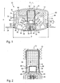
- FIG. 1 shows a gas generator 10 with an outer housing 12, which is composed here of a cup-shaped diffuser 14 having a substantially cylindrical peripheral wall 16 and a closure body 18, which here also forms the bottom of the gas generator 10.
- the closure body 18 has a circumferential, raised edge 20, which rests against the inside of the peripheral wall 16 of the diffuser 14 and is connected by a weld 22 with this firmly.
- the weld 22 preferably extends over the entire contact surface between the closure shell 18 and the diffuser 14 and to the outside of the gas generator 10, where it fills an existing between closure body 18 and diffuser 14 groove.
- a laser welding method can be used for the connection of the diffuser 14 and closure body 18.
- the peripheral wall 16 of the diffuser 14 is bent outward, so that a flat flange 24 running horizontally around the gas generator 10 is formed.
- the closure body 18 has a central opening 26 which serves to receive a prefabricated lighter 28. Towards the central opening 26, the closure body 18 has an indentation 34 with an annular portion 30.
- the indentation 34 is a type of invagination of the outer casing. This area of the gas generator 10 is described in detail in FIGS Figures 2 and 3 shown.
- the lighter 28 is surrounded by a base 32 which connects the lighter 28 also with the closure body 18 and in particular with the edge of the opening 26 and the annular portion 30.
- the base 32 is made of a plastic material and is injection molded after the lighter 28 is inserted into the opening 26.
- the plastic material encloses most of the lighter 28 as well as the edge of the opening 26 and also fills the indentation 34 formed by the annular portion 30 on the outside of the inflator 10, except for an outward igniter plug 38, into the contact pins for an electrical contact of the lighter 28 protrude completely.
- the lighter 38 is simultaneously embedded in the base 32 during encapsulation. Through the base 32 and the lighter 28, the opening 26 is completely closed and the recess 34 is lined by the base, so to speak.
- the lighter 28 is so far enclosed by the base 32, that only its top and a short upper portion of a lighter cap 36 are released.
- the lighter 28 is preferably a separate, prefabricated component.
- the primer cap 36 is either part of the prefabricated lighter 28 or a separate, placed on the lighter 28 component.
- the primer cap 36 consists in this example of a plastic, of a similar plastic as the base 32, preferably of the identical plastic.
- a standard material is used with a glass fiber content, wherein the glass fiber content may be, for example, 30 wt.%.
- the use of a similar or the same plastic causes the igniter cap 36 completely or partially merges with the base 32 during injection molding, and thus forms a dense and permanent connection.
- the indentation 34 can also be formed on a separate part of the gas generator 10, which is connected to the outer housing 12, in particular to the closure body 18.
- a circumferential recess is formed between the closure body 18 and the base 32, which is filled with a sealant 42, here in the form of an acrylate adhesive.
- the sealant 42 is selected so that it adheres to both the metal of the closure shell 18 and the plastic of the base 32.
- the sealing means 42 is applied after the injection molding of the base 32 from the outside and lies completely outside the outer housing 12 of the gas generator 10 and completely in the circumferential recess.
- the sealant 42 is applied in liquid or pasty form and cured with UV light. It has a high flexibility even at low temperatures of up to -40 ° C. It has a low viscosity, so it is easy to process, good wetting properties for both metal and plastic surfaces and adheres to both metal and plastic.
- the sealant has at least one of the following properties: Breaking strength according to ISO 527 [MPa] 2-4, esp. 3; Tear or breaking elongation according to ISO 527 [%] 200-400, especially 300 ⁇ 40; Viscosity at 23 ° C according to Brookfield Sp / U and 3/100 [mPas] 400-800, especially 600 ⁇ 80; Glass transition temperature (rheometer) [° C] 10-30, especially 20 ⁇ 4; Therm.
- the sealant 42 is a dye, preferably a fluorescent dye admixed. This allows a simple check whether the sealing bead has been fully applied and the recess is completely filled with the sealant 42. Upon irradiation with UV light, it is easy to see at what point sealant 42 is due to the fluorescent dye. If a non-fluorescent dye is used, a different color than for the base 32 or the closure body 18 is selected for this, so that it can be seen on the basis of the color whether the sealing bead is complete and circumferential.
- the control can be made using a camera.
- the contact pins 40 of the gas generator 10 are connected via a shorting bridge 44.
- the igniter plug receptacle 38, the base 32 and the sealant 42 are covered in this state by a laminate film 46 and thus protected from environmental influences.
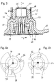
- the recess 34 forming the wall is partially curved in the radial direction r formed (see Fig. 3 ), such that one or more bulges 48, which extend in the radial direction away from the recess 34, are formed.
- the gas generator 10 has a central axis A (see FIG. 1 ). Relative to this central axis A, the curvature which forms the bulge 48 extends annularly around the indentation 34 in this example.
- bulge 48 it is also possible not to form the bulge 48 in the circumferential direction and to provide only one or more, separate bulges 48 along the circumference of the recess 34.
- the course of the wall is in FIG. 3 shown with dashed lines.
- the wall thickness of the wall of the indentation 34 is unchanged here compared to the wall thickness outside the bulge 48.
- the section of the recess 34 in the region of a bulge 48 forms an S-shaped curve, wherein the mouth portion (lower axial end) of the wall forming the recess 34 extends to the outside.
- the indentation 34 has, in addition to the annular portion 30, a bottom portion 50, which adjoins the annular portion 30 in the direction of the interior of the gas generator 10.
- the bottom portion 50 also forms the edge of the opening 26.
- an annular circumferential projection 52 is formed (only in FIG. 3 provided with reference numerals).
- the projection 52 forms a convex shape and is formed without sharp edges.
- the bottom portion On the opposite side (inside), the bottom portion has a preferably rectangular in profile depression, which also extends circumferentially around the edge of the opening 26 and whose opening is directed into the interior of the gas generator 10.
- both the groove 54 and the projection 52 are enclosed in the injection molding of the base 32 of the liquid plastic, so that a solid and tight connection to the base 32 is formed, which withstands temperature fluctuations and during and after the solidification of the plastic is an additional support. Also, the recess 54 is only in FIG. 3 shown with reference number.
- annular, so substantially toroidal combustion chamber 56 is formed (see Fig.1 ), which is filled with a known pyrotechnic gas-generating means 58, here indicated by some tablets.
- the combustion chamber 56 is delimited by a cap 60, which surrounds the lighter 28 and the portion of the base 32 located inside the gas generator 10, as well as an additional space in the form of an intermediate chamber 62 encloses.
- the intermediate chamber 62 is filled with a booster charge of known pyrotechnic gas generating material 64.
- the cap 60 (see Fig. 2 ) has a plurality of overflow openings 66, which create a connection between the intermediate chamber 62 and the combustion chamber 56.
- the cap 60 is made of steel. It is closed at the upper end and open at the lower end and has a substantially cylindrical wall in which the overflow openings 66 are arranged.
- the cap 60 is bent outwardly at the open end, so that a short flange 68 is formed (see FIG. 2 ).
- the cap 60 After introduction of the booster charge 64, the cap 60 is merely pushed onto the base 32 and possibly pressed with this or pushed to form a press fit. A festsch quest progressen is not provided.
- the cap 60 can shift in the upward direction, ie away from the lighter 28.
- the overflow openings 66 also move upwards, ie relative to the propellant charge.
- further regions of the fuel bed in the combustion chamber 56 come into contact with the hot gases flowing out of the intermediate chamber 62 and are ignited.
- FIG. 1 Upper region of the combustion chamber 56, ie on the side opposite the lighter 28 of the outer housing 12, is provided with an elastic member 70, here a filler or volume compensation element, which rests against the top of the diffuser 14.
- the elastic member 70 is here formed of a mesh of wire and is compressible when the cap 60 moves. A further movement margin for the cap 60 is obtained from the bulge of the gas generator 10 during gas evolution, in which the top of the diffuser 14 lifts slightly.
- the elastic member 70 has a central recess 72 into which the cap protrudes to a shoulder and whose upper end portion is slightly smaller than the diameter of the cap 60 to oppose the movement of the cap 60 a defined displacement resistance.
- the cap 60 forms the only partition wall between the intermediate chamber 62 and the combustion chamber 56. It is possible that the cap 60 is lined on the inside with a protective film 74 which closes the overflow openings 66 before the activation of the gas generator 10, wherein the protective film 74 is destroyed at the ignition of the lighter 28.
- the overflow openings 66 lie directly on the upper edge of the base 32 so that they have the greatest possible displacement in the direction of the central axis A.
- a filter 76 is disposed in the combustion chamber 56 which is here annular, substantially cylindrical and parallel to the peripheral wall 16 of the diffuser 14 at a small radial distance therefrom.
- the filter 76 extends over the entire height of the gas generator 10 and extends here from the closure body 18 to the end face of the diffuser 14.
- the filter 76 is formed of a wire mesh or Drahtgewirk with different thickness wires.
- outflow openings 78 are formed, which are distributed uniformly over the circumference of the diffuser 14 and arranged at an axial height.
- the filter 76 separates the exhaust ports 78 from the combustion chamber 56 so that the filter 76 is upstream of the exhaust ports 78.
- the filter 76 is pressed under axial bias in the outer housing 12.
- the filter 76 has two axial ends 80, 82, at least one end of which is angled outwards. In this case, the angled portion is the lower axial end 80 and the angling is rectilinear.
- the filter 76 has the same thickness in the angled region as it has in a middle region adjacent to the angled region.
- the filter 76 is S-shaped when viewed in axial section. Even at the upper axial end 82, namely, a slight bend is provided, which, however, extends to the center of the gas generator 10 (in FIG. 1 on the left half indicated by dashed line).
- the radially innermost contact point of the outwardly angled lower axial end 80 lies radially further outward than the radially outermost contact point of the inwardly angled axial end 82, so that the end-side contact surfaces are laterally completely offset.
- the angled portion at the lower axial end 80 abuts in a corner formed by the housing of the inflator 10.
- the housing part is formed by the closure body 18, and the lower axial end 80 of the filter 76 abuts the transition from a bottom plate of the closure body 18 to the bent-up edge 20 thereof.
- the filter 76 tapers, as shown in particular on the right side of FIG. 1 can be seen. At this end, the filter 76 has a greater length of thin wires in terms of volume than in the adjacent area and preferably as in the rest of the filter, which makes the tapered area very flexible.
- This shaping makes it possible to deform the material during the axial pressing into the gas generator in such a way that no bypass is created for any particles which may be formed when the pyrotechnic material 58 burns off.
- the pyrotechnic material 58 in the combustion chamber 56 is surrounded by metal on all sides, that is, the combustor wall composed of several parts is made of the same material throughout.
- the combustion chamber 56 is enclosed by the elastic filling body 70, the filter 76, the cap 60 and the closure body 80.
- all these components are made of the same metal, preferably of the same steel.
- the outflow openings 78 are closed by a damming 84 in the form of a Däfflemmfolie prior to activation of the gas generator.
- the damming 84 is mounted circumferentially on the inside of the peripheral wall 16 of the diffuser 14 at the level of the outflow openings 78 and covers all outflow openings 78.
- the height of the damming 84 here is approximately four times the diameter of the outflow openings 78.
- the lower end of the baffle 84 that is the end facing the closure body 18, is arranged at a distance from the weld seam 22 which connects the diffuser 14 to the closure body 18.
- the distance a to the weld 22, or in this case equivalent to the end of the upper edge 20 of the closure body 18 is in the case shown about 5.5 mm and is preferably between 3 and 7 mm (see Fig. 1 ). This distance is sufficient to prevent unwanted heat transfer during welding to the baffle 84.
- the outer casing 12 of the gas generator 10 has a relatively thin wall thickness, which in no case exceeds 2 mm in the example shown here.
- the wall thickness of the diffuser is 1.5 mm and that of the closure body 1.9 mm. These wall thicknesses are sufficient to withstand a combustion chamber pressure in the activation of the gas generator 10 of 300 bar.
- the diffuser 14 and the closure body 18 are connected to each other only via the weld 22, so that this weld 22 forms the only strength-determining connection between the components of the outer housing 12.
- a tie rod is preferably not provided.
- the ratio of maximum combustion chamber pressure to wall thickness is preferably between 150 and 220 bar / mm.
- the ratio of the total outflow area of the gas generator 10, ie the sum of the areas of all outflow openings 78, to the wall thickness is here greater than 30, in particular greater than 34 mm.
- the ratio of the diameter D of the diffuser, measured at the diameter of the peripheral wall 16, to the smallest wall thickness of the outer housing is preferably less than 50, and is preferably between 35 and 45.
- the flange 24 is not taken into account in the diameter determination.
- the gas generator 10 has substantially the shape of a flat cylinder, wherein the ratio of diameter D to maximum axial height H is about 1.8 ⁇ 0.2, preferably 1.8 ⁇ 0.1.
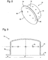
- the flange 24 on the outer circumference of the diffuser 14 is flat but asymmetrical (see FIGS. 4a and b ). This design provides a positioning aid when installing the gas generator 10 in a module, such as a gas bag module by the installation position is clearly specified.
- recessed positioning means 86 are distributed over the circumference of the flange 24, three notches, at different angular intervals.
- the angles between the notches are for example 115 and 148 °, or in another example 93 and 109 °.
- an opening 88 in the form of a slot in the flange 84 is formed. This opening 88 is the only opening provided in the flange 84.
- notches 86 or protrusions may be provided instead of the notches or other suitable mounting positioning means 86.
- the gas generator 10 When installing the gas generator 10 in a module, for example, a in FIG. 7 shown gas bag module 90, the gas generator 10 is fixed by a clamping or retaining element 92 (see also FIGS. 5 to 7 ).
- the holding member 92 has a central opening through which the inflator 10 extends partially therethrough so that the retainer 92 presses against the flange 24.
- the holding member 92 has corresponding mounting positioning means 94, which are complementary to the Einbaupositionierstoffn 86 of the flange 24 of the gas generator 10.
- the mounting positioning means 94 are formed by integrally molded projections in the holding member 92, for example in the form of cut and bent sheet metal sections. The projections engage in the notches and thus clearly indicate the installation position of the gas generator 10.
- the opening 88 in the flange 24 serves to determine the installation position of a gas bag 96 (indicated in FIG FIG. 7 ), which is clamped with the opening edge 100 of its injection opening 98 between the flange 24 and the holding member 92.
- the slot 88 is also usable in the gas generator manufacturing beyond.
- a pin in the tool carrier which is engageable with the slot, the correct positioning of the diffuser (flange) can be ensured to other gas generator components, e.g. for orientation with the igniter pins.
- the gas bag 96 also has an opening (not shown) at the opening edge 100 which is brought into registry with the opening 88 in the flange to properly position the gas bag 96.
- the opening 88 does not serve as Naturalschraubö réelle and is the only opening at the opening edge 100 of the gas bag 96. That means, the clamping of the gas bag 96 between the flange 24 and retainer 92 is effected by fastening means, usually bolts, which lie outside the flange 24. This optimizes the flange surface.
- the holding element 92 has fastening bolts 102, in the example shown four in number, via which the gas bag module 90 can be connected to a vehicle (not shown).
- the mounting bolts 102 abut the outer periphery of the flange 24, but away from the area of the mounting positioning means 86.
- the flange 24 is circumferential and planar.
- the width B of the flange (the transition radius between the planar flange portion and the peripheral wall of the diffuser 14 is between 5 and 12%, preferably between 8 and 11% of the maximum diameter D of the outer housing 12.
- the width B of the clamping surface in the radial direction r is between 5 and 8.5, preferably between 5.5 and 7.5 mm (see Fig. 9 )
- a clamping section 104 is defined relative to the clamping surface on the flange 24 (see Fig. 7 ), which generates a holding force for the gas bag 96 together with the clamping surface on the flange 24.
- the clamping surface and the clamping portion 104 are formed so that the forces acting on the opening edge 100 by the maximum internal pressure in the gas bag 96 forces are 20 to 50% lower than the clamping force generated between the clamping surface and clamping element 104.
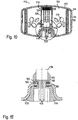
- FIG. 10 shows a particular embodiment of a gas generator 110, which has a first component 112, here made of metal, in the form of a gas generator housing, in the center of which an igniter device 113 is arranged.
- This comprises a lighter, which is a second component 114 which is connected via a molded plastic base 116 with the first component 112 by both components are at least partially encapsulated together.
- the lighter here is a prefabricated, completed by a metallic outer shell Component and has a plurality of partially embedded in the plastic base 116 connecting lines 118, which protrude through an opening 120 in the first component 112 (the gas generator housing) from the latter.
- the opening 120 simultaneously serves to receive and fix the second component 114 (of the lighter), wherein, in particular, the portion 122 of the opening 120 forming the edge of the first component 112 is embedded in the plastic base 116 during spraying.
- the upper end of the lighter adjoins an amplifier chamber 124 filled with booster charge.
- a sleeve 126 delimiting the booster chamber 124 which has a plurality of overflow openings 128, is placed on the lighter or plastic base 116.
- the booster chamber 124 is surrounded by a combustion chamber 130, which is filled with a schematically shown fuel 132 in tablet form and the outside of a filter 134 adjacent.
- the gas generator housing has on its peripheral wall discharge openings 136 which are protected in the installed state by a Däfflemmfolie 138 from moisture.
- a gas is generated in a known manner, which passes through the outflow openings 136 to the outside and serves, for example, to fill a gas bag of a vehicle occupant restraint system.
- the latter In the contact area 140 between the plastic base 116 and the first component 112, which is located close to the opening 120 or the edge 122, the latter is provided with an adhesive film 142, which has already been applied prior to spraying the plastic base 116.
- the adhesive film 142 covers only a portion of the overmolded region of the first component 112. The adhesive film 142, however, runs closed at the edge 122.
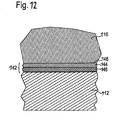
- the adhesive film 142 is a pre-fabricated component and consists of a plastic film 144 and a directly and evenly applied adhesive layer 146 (see FIG Fig. 12 ).
- the same material is used in this example as for the plastic base 116.
- a different material which is suitable to enter into a firm connection with the material of the plastic base 116. This may be about a thermoplastic elastomer.
- the adhesive film 142 serves as a bonding layer between the plastic base 116 and the first component 112.
- the surface of the adhesive film 142 may of course also extend over the entire overmolded portion of the component 112 or project beyond it. It is also conceivable to provide a corresponding adhesive film between the second component 114 and the plastic base 116 as well.
- the gas generator 110 is manufactured as follows: First, the first component 112 (the gas generator housing) and the second component 114 (the lighter) are provided, and the first component 112 is connected to the later connection area of the components (which just corresponds to the contact area 140) Adhesive film 142 provided by one or more suitably cut pieces of adhesive film 142 are adhered to the corresponding locations of the first component 112, here both sides in the region of the edge 122, with the adhesive layer 146.
- the adhesive of the adhesive layer 146 can already be activated or cured by the contact pressure when sticking.
- the activation is by heating, which is e.g. happens during the overmolding by the action of heat by the liquid plastic.
- the second component 114 is positioned relative to the first component 112, and both components 112, 114 are molded together to form the plastic base 116, wherein both components 112, 114 at least partially in the plastic base 116 are embedded.
- the material of the plastic film 144 connects to the injected plastic by a surface layer of the plastic film 144 merges in a connecting zone 148 with the plastic base 116.
- a chemical reaction between the material of the plastic film 144 and that of the plastic base 116 take place, which firmly and inextricably connects the plastic film 144 and the plastic base.
- the adhesive layer 146 forms a bonding layer between the first component 112 and the plastic base 116, which is elastically and / or plastically deformable, so that stresses and shear forces, which occur due to the different thermal expansion coefficients of the different materials.
- the adhesive layer 146 also acts as a seal between the first component 112 and the plastic base 116.
- the invention relates to a gas generator 10 for a protective device in a vehicle, comprising a plurality of parts, wherein in the region of abutting parts, a sealing means 42 is applied, which on both adhering parts, wherein the abutting parts each form at least a part of the outer gas generator surface and wherein the sealing means (42) is applied from the outside to the two abutting parts, so that it lies completely outside an outer casing of the gas generator (10), wherein the abutting Parts of different materials, on the one hand made of plastic and on the other hand made of metal, are made, wherein the part made of plastic forms a partial encapsulation of the part of metal.
- the plastic part is a socket 32 for a lighter 28.
- the base 32 embeds a prefabricated lighter 28 in sections.
- the base 32 forms an igniter plug receptacle 38.
- the part made of metal is an outer casing part of the gas generator 10.
- the plastic part is molded onto the edge of an opening 26 in the outer housing part in order to close it.
- sealing means 42 is applied from outside the gas generator 10 to the transition edge of the abutting parts.
- sealing means 42 is introduced into a recess provided at the transition of the abutting parts.
- sealant 42 is liquid in the order state and / or is an adhesive.
- sealing means 42 can be applied in liquid form and then cured with UV light.
- the sealant 42 has at least one of the following properties: Breaking strength according to ISO 527 [MPa]: 2-4, especially 3; Tear or elongation at break according to ISO 527 [%]: 200-400, especially 300 ⁇ 40; Viscosity at 23 ° C according to Brookfield Sp / U and 3/100 [mPas] 400-800, especially 600 ⁇ 80; Glass transition temperature Rheometer [° C] 10-30, especially 20 ⁇ 4; Therm.
- the sealant 42 contains a dye and / or a different color from the plastic of the part to which the sealant 42 is attached.
- the invention relates to a module with a gas generator 10, 110, an airbag 96 inflatable by the gas generator 10, 110 and a gas bag Fastening device for mounting the module, in particular in the interior of a vehicle, wherein the gas generator 10, 110 is formed according to at least one of the embodiments described above.
Description
Die Erfindung betrifft einen Gasgenerator nach dem Oberbegriff des Anspruch 1.The invention relates to a gas generator according to the preamble of claim 1.
Gasgeneratoren für Schutzeinrichtungen in einem Fahrzeug treiben z.B. Teile (Aufstellen von Motorhauben, Straffen des Gurtes, Verschieben von Polstern oder dergleichen) an oder blasen Gassäcke auf.Gas generators for protective devices in a vehicle drive e.g. Parts (putting on bonnets, straightening the belt, moving upholstery or the like) or inflate airbags.
Aus den Schriften
Die Erfindung verbessert eine solche bekannte Konstruktion hinsichtlich eines zusätzlichen Schutzes des Gasgenerators gegen äußere Umwelteinflüsse, weiter hinsichtlich einer Möglichkeit einer elektrisch nichtleitenden Ausführung eines Bereichs eines Außengehäuses des Gasgenerators und weiter hinsichtlich einer Erhöhung einer Flexibilität bei der Fertigung des Gasgenerators durch das kennzeichnende Merkmal von Anspruch 1.The invention improves such a known construction in terms of additional protection of the gas generator against external environmental influences, further regarding a possibility of electrically non-conductive execution of a portion of an outer casing of the gas generator and further in terms of increasing flexibility in the manufacture of the gas generator by the characterizing feature of claim 1 ,
Gasgeneratoren müssen über viele Jahre für den singulären Einsatz funktionsfähig sein, das heißt, sie können in dieser Zeit hohen Anforderungen ausgesetzt sein, was Beständigkeit gegenüber Umwelteinflüssen wie Feuchteeintritt oder Korrosion angeht.Gas generators must be able to function singularly for many years, which means that they can be exposed to high demands in terms of resistance to environmental influences such as moisture ingress or corrosion.
Gasgeneratoren bestehen aus mehreren miteinander verbundenen Teilen. Zwischen aneinanderstoßenden Teilen besteht das Erfordernis einer auch über viele Jahre hinweg zuverlässigen Verbindung als Schutz gegen äußere Umwelteinflüsse.Gas generators consist of several interconnected parts. Between abutting parts is the requirement of a reliable connection over many years as protection against external environmental influences.
Die Erfindung sieht einen Gasgenerator gemäß der zuvor beschriebenen Art vor, bei dem die aneinanderstoßenden Teile aus unterschiedlichen Materialien, einerseits aus Kunststoff und andererseits aus Metall, bestehen, wobei das aus Kunststoff bestehende Teil eine teilweise Umspritzung des Teiles aus Metall bildet.The invention provides a gas generator according to the previously described type, in which the abutting parts of different materials, on the one hand of plastic and on the other hand of metal, consist, wherein the plastic part forming a partial encapsulation of the metal part.
Aufgrund der stark unterschiedlichen Ausdehnungskoeffizienten und Eigenschaften dieser Teile wird durch die Erfindung ein optimierter Schutz gegen Umwelteinflüsse bereitgestellt. Obwohl eine solche Umspritzung eine dichte, auch feuchtedichte Verbindung zwischen diesen Teilen sicherstellt, die auch neben dem Formschluss Adhäsion ermöglicht, wird durch das Dichtmittel eine zusätzliche Sicherheit gegen Umwelteinflüsse über die Lebensdauer eines Gasgenerators geschaffen, denn es wäre zumindest theoretisch denkbar, dass im Lauf der Jahre könnten durch die unterschiedlichen Wärmeausdehnungen und das unterschiedliche Ausdehnungsverhalten eventuell kleine Spalte entstehen könnten.Due to the greatly different expansion coefficients and properties of these parts, an optimized protection against environmental influences is provided by the invention. Although such an encapsulation ensures a dense, even moisture-tight connection between these parts, which also allows adhesion in addition to the positive, the sealant provides additional protection against environmental influences over the life of a gas generator, because it would be at least theoretically conceivable that in the course of Years could be caused by the different thermal expansions and the different expansion behavior possibly small gaps.
Das Dichtmittel übernimmt vorzugsweise keine mechanische oder adhäsive Haltefunktion zwischen den aneinanderstoßenden Teilen, die anderweitig miteinander verbunden sind. Das heißt, der Gasgenerator ist auch ohne Dichtmittel so ausgelegt, dass die aneinanderstoßenden Teile lagefest positioniert sind.The sealant preferably does not assume any mechanical or adhesive retention function between the abutting parts that are otherwise connected together. That is, the gas generator is designed without sealant so that the abutting parts are positioned stable.
Durch Haften des Dichtmittels an beiden aneinanderstoßenden Teilen wird vermieden, dass Feuchtigkeit in das Innere des Gasgenerators eindringen kann.Adhering the sealant to both abutting parts prevents moisture from entering the interior of the inflator.
In diesem Zusammenhang ist zu erwähnen, dass Gasgeneratoren und damit die Verbindung der Teile sowie die Wirksamkeit des Dichtmittels in einem Einsatztemperaturbereich von mindestens -40° bis wenigstens 120° C zuverlässig arbeiten bzw. wirken müssen. Um diese Eigenschaften zu erfüllen, hat das Dichtmittel eine hohe Flexibilität, auch bei tiefen Temperaturen. Weitere Eigenschaften sind eine geringe Viskosität im flüssigen Zustand beim Auftrag zum Eindringen in Mikrospalte eine gute Benetzung der unterschiedlichen Oberflächen und möglichst eine schnelle Aushärtung.In this context, it should be mentioned that gas generators and thus the connection of the parts and the effectiveness of the sealant in a service temperature range of at least -40 ° to at least 120 ° C work reliably or have to act. To meet these requirements, the sealant has a high flexibility, even at low temperatures. Further properties are a low viscosity in the liquid state when applied for penetration into micro-gaps, a good wetting of the different surfaces and preferably a rapid curing.
Diese schnelle Aushärtung kann beispielsweise dadurch erreicht werden, dass das Dichtmittel flüssig aufzubringen und anschließend UV-aushärtbar ist.This rapid curing can be achieved, for example, by applying the sealant in liquid form and then UV-curable.
Wie zuvor bereits erwähnt, ist das Dichtmittel insbesondere bei einem Gasgenerator zwischen einem Kunststoffteil und einem Metallteil eingesetzt. Ein bevorzugtes Ausführungsbeispiel ist dabei die zusätzliche Abdichtung zwischen einem Sockel eines Anzünders, der aus Kunststoff besteht, und dem angrenzenden Gehäuseteil des Gasgenerators, welches üblicherweise aus Metall ist. Im Übergangsbereich zwischen Sockel und Gehäuseteil weist der erfindungsgemäße Gasgenerator das Dichtmittel auf.As already mentioned above, the sealing means is used in particular in a gas generator between a plastic part and a metal part. A preferred embodiment is the additional seal between a base of a lighter, which consists of plastic, and the adjacent housing part of the gas generator, which is usually made of metal. In the transition region between the base and the housing part, the gas generator according to the invention comprises the sealant.
Der Sockel kann durch Umspritzen des Teiles aus Metall gebildet sein.The base may be formed by overmolding the metal part.
Vorzugsweise ist in den Sockel auch ein vorgefertigter Anzünder abschnittsweise eingebettet, was insbesondere beim Spritzgießen erfolgt.Preferably, a prefabricated lighter is embedded in sections in the base, which takes place in particular during injection molding.
Der Sockel bildet zudem vorzugsweise eine Anzündersteckeraufnahme aus, das heißt, der Zünderstecker, der auf die Kontaktstifte gesteckt wird, wird im Sockel selbst gehaltert.The base also preferably forms an igniter plug receptacle, that is, the igniter plug that is plugged onto the contact pins is held in the socket itself.
Das aus Metall bestehende Teil kann ein Außengehäuseteil des Gasgenerators sein. Das Dichtmittel wird von außen auf die Teile aufgebracht, nachdem sie bereits miteinander verbunden sind und nicht während der Verbindung der Teile.The metal part may be an outer shell part of the inflator. The sealant is applied to the parts from the outside after they are already connected to each other and not during the connection of the parts.
Das aus Kunststoff bestehende Teil ist zum Beispiel an den Rand einer Öffnung im Außengehäuseteil angespritzt, um dieses zu schließen.The plastic part is for example molded onto the edge of an opening in the outer housing part in order to close it.
Das Dichtmittel wird darüber hinaus vorzugsweise auch nicht großflächig auf den Gasgenerator aufgebracht, sondern nur am Übergangsrand der aneinanderstoßenden Teile. Zum Schutz des Dichtmittels ist dieses insbesondere in einer am Übergang der aneinanderstoßenden Teile vorgesehenen Vertiefung eingebracht. Das Dichtmittel kann dabei die Vertiefung vollständig oder nahezu vollständig ausfüllen. Vorzugsweise steht das Dichtmittel nicht gegenüber der Vertiefung nach außen vor. Insbesondere entsteht die Vertiefung durch zwei aneinanderstoßende Radien der beiden benachbarten Teile, die eine geschwungen V-förmige Nut generieren.The sealant is also preferably not applied over a large area on the gas generator, but only at the transition edge of the abutting parts. To protect the sealant this is introduced in particular in a recess provided at the transition of the abutting parts. The sealant can fill the depression completely or almost completely. Preferably, the sealant does not project outwardly of the recess. In particular, the recess is formed by two abutting radii of the two adjacent parts that generate a curved V-shaped groove.
Eine bevorzugte Ausführungsform der Erfindung sieht vor, dass das Dichtmittel ein Kleber, insbesondere Acrylatkleber ist.A preferred embodiment of the invention provides that the sealing means is an adhesive, in particular acrylate adhesive.
Die bevorzugten mechanischen, chemischen und physikalischen Eigenschaften des Dichtmittels sind in den Ansprüchen angegeben, wobei zu betonen ist, dass eine oder mehrere dieser genannten Eigenschaften vorhanden sein sollten.The preferred mechanical, chemical and physical properties of the sealant are set out in the claims, it being understood that one or more of these properties should be present.
Beim Auftrag des Dichtmittels ist es wichtig, dass dieses an allen erforderlichen, vorbestimmten Stellen aufgetragen wird. Gemäß einer bevorzugten Ausführungsform ist vorgesehen, dass das Dichtmittel einen Farbstoff, insbesondere fluoreszierenden Farbstoff enthält, mittels dem die Erstreckung des Dichtmittels kontrolliert werden kann. Die Farbe im Dichtmittel sollte sich deutlich von der (falls vorhanden) Farbe des Kunststoffes des Teiles oder, allgemeiner, der Teile, an die das Dichtmittel angrenzt, unterscheiden.When applying the sealant, it is important that this is applied at all required, predetermined locations. According to a preferred embodiment, it is provided that the sealant contains a dye, in particular fluorescent dye, by means of which the extent of the sealant can be controlled. The color in the sealant should be significantly different from the color (if any) of the plastic of the part or, more generally, the parts to which the sealant is adjacent.
Die Kontrolle bezüglich der Erstreckung des Auftrags des Dichtmittels kann gegebenenfalls sogar automatisch über eine Kamera erfolgen.The control with respect to the extension of the order of the sealant may optionally even be done automatically via a camera.
Bei Verwendung eines fluoreszierenden Farbstoffs wird das Dichtmittel, genauer gesagt die durch das Dichtmittel gebildete Raupe, mit UV-Licht bestrahlt, was eine besonders einfache, vollautomatische Kontrolle erlaubt.When using a fluorescent dye, the sealant, more precisely, the bead formed by the sealant, is irradiated with UV light, which allows a particularly simple, fully automatic control.
Des Weiteren liegt der Erfindung die Aufgabe zu Grunde, ein Modul mit einem Gasgenerator, einem von dem Gasgenerator aufblasbarem Gassack und einer Befestigungseinrichtung zur Anbringung des Moduls, insbesondere im Innenbereich eines Fahrzeuges, derart zu verbessern, dass dessen Herstellungskosten reduziert werden und/oder ein zusätzlicher Schutz für das Modul insgesamt gegen äußere Umwelteinflüsse erreicht werden können.Furthermore, the object of the invention is to improve a module with a gas generator, an airbag inflatable by the gas generator and a fastening device for mounting the module, in particular in the interior of a vehicle, such that its production costs are reduced and / or an additional one Protection for the module can be achieved in total against external environmental influences.
Diese Aufgabe wird für ein solches Modul erfindungsgemäß dadurch gelöst, dass der Gasgenerator nach zumindest einem der Ansprüche 1 bis 11 ausgebildet ist.This object is achieved for such a module according to the invention in that the gas generator is designed according to at least one of claims 1 to 11.
Weitere Merkmale und Vorteile der Erfindung ergeben sich aus der nachfolgenden Beschreibung mehrerer bevorzugter Ausführungsformen in Verbindung mit den beigefügten Zeichnungen. In diesen zeigen:
-
Figur 1 eine Schnittansicht eines erfindungsgemäßen Gasgenerators; -
Figur 2 eine Detailansicht ausFigur 1 ; -
Figur 3 eine weitere Detailansicht ausFigur 1 ; -
Figur 4a eine schematische Draufsicht auf den Flansch eines erfindungsgemäßen Gasgenerators; -
Figur 4b eine Variante des Flansches inFigur 4a ; -
Figuren 5 und 6 jeweils eine schematische perspektivische Darstellung eines Gassackhalteblechs eines erfindungsgemäßen Moduls, insbesondere Gassackmoduls, mit einem eingebauten erfindungsgemäßen Gasgenerator; -
Figur 7 eine schematische Querschnittsansicht eines erfindungsgemäßen Moduls mit einem erfindungsgemäßen Gasgenerator; -
Figur 8 eine schematische perspektivische Darstellung eines Diffusors eines erfindungsgemäßen Gasgenerators; und -
Figur 9 eine schematische Schnittansicht des Diffusors inFigur 8 . -
Figur 10 -
Figur 11 ein vergrößertes Detail ausFigur 10 -
Figur 12
-
FIG. 1 a sectional view of a gas generator according to the invention; -
FIG. 2 a detailed viewFIG. 1 ; -
FIG. 3 another detail viewFIG. 1 ; -
FIG. 4a a schematic plan view of the flange of a gas generator according to the invention; -
FIG. 4b a variant of the flange inFIG. 4a ; -
FIGS. 5 and 6 in each case a schematic perspective view of a gas bag retaining plate of a module according to the invention, in particular gas bag module, with a built-in gas generator according to the invention; -
FIG. 7 a schematic cross-sectional view of a module according to the invention with a gas generator according to the invention; -
FIG. 8 a schematic perspective view of a diffuser of a gas generator according to the invention; and -
FIG. 9 a schematic sectional view of the diffuser inFIG. 8 , -
FIG. 10 a sectional view of a gas generator; -
FIG. 11 an enlarged detailFIG. 10 showing the connection of a first and a second component; and -
FIG. 12 increases the transition from the first to the second component.
Der Verschlusskörper 18 besitzt einen umlaufenden, hochgezogenen Rand 20, der an der Innenseite der Umfangswand 16 des Diffusors 14 anliegt und mittels einer Schweißnaht 22 mit dieser fest verbunden ist. Die Schweißnaht 22 erstreckt sich vorzugsweise über die gesamte Anlagefläche zwischen Verschlussschale 18 und Diffusor 14 und bis zur Außenseite des Gasgenerators 10, wo sie eine zwischen Verschlusskörper 18 und Diffusor 14 bestehende Nut ausfüllt. Zur Verbindung von Diffusor 14 und Verschlusskörper 18 kann beispielsweise ein Laserschweißverfahren eingesetzt werden.The
Am verschlusskörperseitigen Ende ist die Umfangswand 16 des Diffusors 14 nach außen gebogen, sodass ein horizontal um dem Gasgenerator 10 umlaufender, planer Flansch 24 gebildet ist.At the closure body-side end, the
Der Verschlusskörper 18 hat eine zentrale Öffnung 26, die zur Aufnahme eines vorgefertigten Anzünders 28 dient. Zur zentralen Öffnung 26 hin hat der Verschlusskörper 18 eine Einbuchtung 34 mit einem ringförmigen Abschnitt 30. Die Einbuchtung 34 ist eine Art Einstülpung des Außengehäuses. Dieser Bereich des Gasgenerators 10 ist im Detail in den
Der Anzünder 28 ist von einem Sockel 32 umgeben, der den Anzünder 28 auch mit dem Verschlusskörper 18 und insbesondere mit dem Rand der Öffnung 26 und dem ringförmigen Abschnitt 30 verbindet.The lighter 28 is surrounded by a base 32 which connects the lighter 28 also with the
Der Sockel 32 besteht aus einem Kunststoffmaterial und wird spritzgegossen, nachdem der Anzünder 28 in die Öffnung 26 eingebracht wurde. Beim Spritzgießen umschließt das Kunststoffmaterial sowohl den größten Teil des Anzünders 28 als auch den Rand der Öffnung 26 und füllt auch die durch den ringförmigen Abschnitt 30 gebildete Einbuchtung 34 auf der Außenseite des Gasgenerators 10 mit Ausnahme einer nach außen gerichteten Zündersteckeraufname 38, in die Kontaktstifte für eine elektrische Kontaktierung des Anzünders 28 hineinragen, vollständig aus. Der Anzünder 38 wird beim Umspritzen gleichzeitig in den Sockel 32 eingebettet. Durch den Sockel 32 und den Anzünder 28 ist die Öffnung 26 vollständig verschlossen und die Einbuchtung 34 wird vom Sockel sozusagen ausgekleidet.The
In diesem Fall ist der Anzünder 28 so weit vom Sockel 32 umschlossen, dass lediglich seine Oberseite sowie ein kurzer oberer Abschnitt einer Anzünderkappe 36 freigelassen sind.In this case, the lighter 28 is so far enclosed by the
Der Anzünder 28 ist vorzugsweise ein separates, vorgefertigtes Bauteil. Die Anzünderkappe 36 ist entweder Teil des vorgefertigten Anzünders 28 oder ein separates, auf den Anzünder 28 aufgesetztes Bauteil.The lighter 28 is preferably a separate, prefabricated component. The
Die Anzünderkappe 36 besteht in diesem Beispiel aus einem Kunststoff, und zwar aus einem gleichartigen Kunststoff wie der Sockel 32, vorzugsweise aus dem identischen Kunststoff. Vorzugsweise wird ein Standardmaterial mit einem Glasfaseranteil eingesetzt, wobei der Glasfaseranteil zum Beispiel 30 Gew.% betragen kann. Die Verwendung eines gleichartigen oder gleichen Kunststoffes führt dazu, dass beim Spritzgießen die Anzünderkappe 36 ganz oder teilweise mit dem Sockel 32 verschmilzt, und sich so eine dichte und unlösbare Verbindung bildet.The
Die Einbuchtung 34 kann natürlich auch an einem separaten Teil des Gasgenerators 10 ausgebildet sein, der mit dem Außengehäuse 12, insbesondere mit dem Verschlusskörper 18 verbunden ist.Of course, the
An der Außenseite der Einbuchtung 34 ist zwischen dem Verschlusskörper 18 und dem Sockel 32 eine umlaufende Vertiefung gebildet, die mit einem Dichtmittel 42, hier in Form eines Acrylatklebers ausgefüllt ist.On the outside of the
Das Dichtmittel 42 ist so ausgewählt, dass es sowohl am Metall der Verschlussschale 18 als auch am Kunststoff des Sockels 32 haftet. Das Dichtmittel 42 wird nach dem Spritzgießen des Sockels 32 von außen aufgebracht und liegt vollständig außerhalb des Außengehäuses 12 des Gasgenerators 10 und komplett in der umlaufenden Vertiefung.The
Das Dichtmittel 42 wird in flüssiger oder pastöser Form aufgebracht und mit UV-Licht ausgehärtet. Es weist eine hohe Flexibilität auch bei tiefen Temperaturen von bis zu -40°C auf. Es hat eine geringe Viskosität, so dass es sich leicht verarbeiten lässt, gute Benetzungseigenschaften sowohl für Metall- als auch für Kunststoffoberflächen und haftet sowohl auf Metall als auch auf Kunststoff.The
Das Dichtmittel besitzt wenigstens eine der folgenden Eigenschaften:
Dem Dichtmittel 42 ist ein Farbstoff, vorzugsweise ein Fluoreszenzfarbstoff, beigemischt. Dies erlaubt eine einfache Kontrolle, ob die Dichtraupe vollständig aufgebracht wurde und die Vertiefung komplett mit dem Dichtmittel 42 gefüllt ist. Bei einer Bestrahlung mit UV-Licht ist aufgrund des fluoreszierenden Farbstoffs einfach zu erkennen, an welcher Stelle sich Dichtmittel 42 befindet. Wird ein nicht fluoreszierender Farbstoff verwendet, so ist für diesen eine andere Farbe als für den Sockel 32 beziehungsweise den Verschlusskörper 18 gewählt, so dass an Hand der Farbe zu erkennen ist, ob die Dichtraupe vollständig und umlaufend ist.The
Die Kontrolle kann unter Einsatz einer Kamera vorgenommen werden.The control can be made using a camera.
Vor seiner Montage in ein Gassackmodul sind die Kontaktstifte 40 des Gasgenerators 10 über eine Kurzschlussbrücke 44 verbunden. Die Zündersteckeraufnahme 38, der Sockel 32 und das Dichtmittel 42 sind in diesem Zustand durch eine Laminatfolie 46 abgedeckt und so vor Umwelteinflüssen geschützt.Before being mounted in an airbag module, the contact pins 40 of the
Die die Einbuchtung 34 bildende Wand ist abschnittsweise in radialer Richtung r gewölbt ausgebildet (siehe
Es ist auch möglich, die Ausbauchung 48 in Umfangsrichtung nicht durchgängig auszubilden und nur eine oder mehrere, separate Ausbauchungen 48 entlang des Umfangs der Einbuchtung 34 vorzusehen. Der Verlauf der Wand ist in
In dem in
Die Einbuchtung 34 weist neben dem ringförmigen Abschnitt 30 einen Bodenabschnitt 50 auf, der sich in Richtung zum Inneren des Gasgenerators 10 an den ringförmigen Abschnitt 30 anschließt. Der Bodenabschnitt 50 bildet auch den Rand der Öffnung 26. Am Bodenabschnitt 50 am Rand der Öffnung 26 ist zur Außenseite des Gasgenerators hin ein ringförmig umlaufender Vorsprung 52 ausgebildet (nur in
Sowohl die Nut 54 als auch der Vorsprung 52 werden beim Spritzgießen des Sockels 32 vom flüssigen Kunststoff umschlossen, so dass sich eine feste und dichte Verbindung zum Sockel 32 ausbildet, die auch Temperaturschwankungen standhält sowie während und nach dem Erstarren des Kunststoffs eine zusätzliche Halterung darstellt. Auch die Vertiefung 54 ist nur in
Im Inneren des Außengehäuses 12 ist eine ringförmige, also im Wesentlichen toroidale Brennkammer 56 gebildet (siehe
Zur Mittelachse A des Gasgenerators 10 hin wird die Brennkammer 56 durch eine Kappe 60 begrenzt, die den Anzünder 28 und den im Inneren des Gasgenerators 10 liegenden Abschnitt des Sockels 32 sowie zusätzlich einen Freiraum in Form einer Zwischenkammer 62 umschließt. Die Zwischenkammer 62 ist mit einer Verstärkerladung aus bekanntem pyrotechnischem, gaserzeugenden Material 64 gefüllt.Towards the center axis A of the
Die Kappe 60 (siehe
Der in
Das elastische Bauteil 70 hat eine zentrale Ausnehmung 72, in die die Kappe bis zu einem Absatz hineinragt und deren oberer Endabschnitt etwas kleiner ist als der Durchmesser der Kappe 60, um der Bewegung der Kappe 60 einen definierten Verschiebewiderstand entgegenzusetzen.The
In diesem Fall bildet die Kappe 60 die einzige Trennwand zwischen der Zwischenkammer 62 und der Brennkammer 56. Es ist möglich, dass die Kappe 60 innenseitig mit einer Schutzfolie 74 ausgekleidet ist, die vor der Aktivierung des Gasgenerators 10 die Überströmöffnungen 66 verschließt, wobei die Schutzfolie 74 bei der Zündung des Anzünders 28 zerstört wird.In this case, the
Im Zustand vor der Aktivierung, der in
Ein Filter 76 ist in der Brennkammer 56 angeordnet, der hier ringförmig, im wesentlichen zylindrisch ausgebildet ist und parallel zur Umfangswand 16 des Diffusors 14 mit einem geringen radialen Abstand zu dieser verläuft.A
Der Filter 76 erstreckt sich über die gesamte Höhe des Gasgenerators 10 und reicht hier vom Verschlusskörper 18 bis zur Stirnseite des Diffusors 14. Der Filter 76 ist aus einem Drahtgestrick oder Drahtgewirk mit unterschiedlich dicken Drähten gebildet.The
In der Umfangswand 16 des Diffusors 14 sind mehrere, in diesem Beispiel zwölf, Ausströmöffnungen 78 ausgebildet, die gleichmäßig über den Umfang des Diffusors 14 verteilt und auf einer axialen Höhe angeordnet sind. Der Filter 76 trennt die Ausströmöffnungen 78 von der Brennkammer 56, so dass der Filter 76 stromaufwärts der Ausströmöffnungen 78 liegt.In the
Der Filter 76 ist unter axialer Vorspannung in das Außengehäuse 12 eingepresst.The
Der Filter 76 weist zwei axiale Enden 80, 82 auf, von denen wenigstens ein Ende nach außen abgewinkelt ist. In diesem Fall ist der abgewinkelte Bereich das untere axiale Ende 80 und die Abwinkelung verläuft geradlinig. Der Filter 76 hat im abgewinkelten Bereich die gleiche Dicke, die er auch in einem mittleren Bereich hat, der an den abgewinkelten Bereich angrenzt.The
Im gezeigten Beispiel verläuft der Filter 76 im axialen Schnitt gesehen S-förmig. Auch am oberen axiale Ende 82 ist nämlich eine leichte Abwinkelung vorgesehen, die sich jedoch zur Mitte des Gasgenerators 10 hin erstreckt (in
Beim Filter 76liegt die radial Innerste Anlagestelle des nach außen abgewinkelten unteren axialen Endes 80 radial weiter außen als die radial äußerste Anlagestelle des nach innen abgewinkelten axialen Endes 82, so dass die stirnseitigen Anlageflächen seitlich vollständig versetzt sind.In the case of the
Der abgewinkelte Bereich am unteren axiale Ende 80 liegt in einer durch das Gehäuse des Gasgenerators 10 gebildete Ecke an. In diesem Fall ist das Gehäuseteil durch den Verschlusskörper 18 gebildet, und das untere axiale Ende 80 des Filters 76 liegt am Übergang von einer Bodenplatte des Verschlusskörpers 18 zum hochgebogenen Rand 20 desselben an.The angled portion at the lower
Am oberen axialen Ende 82 verjüngt sich der Filter 76, wie dies insbesondere auf der rechten Seite der
Diese Formgebung erlaubt es, das Material beim axialen Einpressen in den Gasgenerator so zu verformen, dass kein Bypass für eventuell beim Abbrand des pyrotechnischen Materials 58 entstehende Partikel entsteht.This shaping makes it possible to deform the material during the axial pressing into the gas generator in such a way that no bypass is created for any particles which may be formed when the
Das pyrotechnische Material 58 in der Brennkammer 56 ist auf allen Seiten von Metall umgeben, d.h., die aus mehreren Teilen zusammengesetzte Brennkammerwand besteht durchgehend aus demselben Material. Die Brennkammer 56 wird durch den elastischen Füllkörper 70, den Filter 76, die Kappe 60 sowie den Verschlusskörper 80 umschlossen. Vorzugsweise bestehen, wie gesagt, alle diese Bauteile aus demselben Metall, bevorzugt aus dem gleichen Stahl.The
Die Ausströmöffnungen 78 sind vor der Aktivierung des Gasgenerators 10 durch eine Verdämmung 84 in Form einer Verdämmfolie verschlossen. Die Verdämmung 84 ist umlaufend an der Innenseite der Umfangswand 16 des Diffusors 14 auf Höhe der Ausströmöffnungen 78 angebracht und überdeckt sämtliche Ausströmöffnungen 78. Die Höhe der Verdämmung 84 beträgt hier etwa das vierfache des Durchmessers der Ausströmöffnungen 78.The
Das untere Ende der Verdämmung 84, also das dem Verschlusskörper 18 zugewandten Ende, ist mit Abstand zur Schweißnaht 22, die den Diffusor 14 mit dem Verschlusskörper 18 verbindet, angeordnet. Der Abstand a zur Schweißnaht 22, oder in diesem Fall gleichbedeutend zum Ende des oberen Rand 20 des Verschlusskörpers 18, beträgt im gezeigten Fall etwa 5,5 mm und liegt vorzugsweise zwischen 3 und 7 mm (siehe
Das Außengehäuse 12 des Gasgenerators 10 weist eine relativ dünne Wandstärke auf, die bei dem hier gezeigten Beispiel an keiner Stelle 2 mm überschreitet. Insbesondere beträgt die Wandstärke des Diffusors 1,5 mm und die des Verschlusskörpers 1,9 mm. Diese Wandstärken sind ausreichend, um einem Brennkammerdruck bei der Aktivierung des Gasgenerators 10 von 300 bar standzuhalten.The
Der Diffusor 14 und der Verschlusskörper 18 sind nur über die Schweißnaht 22 miteinander verbunden, so dass diese Schweißnaht 22 die einzige festigkeitbestimmende Verbindung zwischen den Bauteilen des Außengehäuses 12 bildet. Ein Zuganker ist vorzugsweise nicht vorgesehen.The
Das Verhältnis von maximalem Brennkammerdruck zur Wandstärke liegt hier vorzugsweise zwischen 150 und 220 bar/mm.The ratio of maximum combustion chamber pressure to wall thickness is preferably between 150 and 220 bar / mm.
Das Verhältnis der gesamten Ausströmfläche des Gasgenerators 10, also der Summe der Flächen sämtlicher Ausströmöffnungen 78, zur Wandstärke ist hier größer als 30, insbesondere größer als 34 mm.The ratio of the total outflow area of the
Das Verhältnis des Durchmessers D des Diffusors, gemessen am Durchmesser der Umfangswand 16, zur kleinsten Wandstärke des Außengehäuses ist vorzugsweise kleiner als 50, und liegt vorzugsweise zwischen 35 und 45. Der Flansch 24 wird bei der Durchmesserbestimmung nicht berücksichtigt.The ratio of the diameter D of the diffuser, measured at the diameter of the
Der Gasgenerator 10 hat im wesentlichen die Form eines flachen Zylinders, wobei das Verhältnis Durchmesser D zu größter axialer Höhe H etwa 1,8 ± 0,2, vorzugsweise 1,8 ± 0,1 beträgt.The
Der Flansch 24 am Außenumfang des Diffusors 14 ist plan, aber unsymmetrisch gestaltet (siehe
Im vorliegenden Beispiel sind als Einbaupositioniermittel 86 über den Umfang des Flansches 24 drei Kerben verteilt, und zwar in unterschiedlichen Winkelabständen. Die Winkel zwischen den Kerben betragen beispielsweise 115 und 148°, oder in einem anderen Beispiel 93 und 109°.In the present example, as recessed positioning means 86 are distributed over the circumference of the
Als zusätzliches oder alternatives Einbaupositioniermittel ist eine Öffnung 88 in Form eines Langlochs im Flansch 84 ausgebildet. Diese Öffnung 88 ist die einzige Öffnung, die im Flansch 84 vorgesehen ist.As an additional or alternative installation positioning means an
Es können natürlich auch mehr oder weniger Kerben 86 oder Vorsprünge an Stelle der Kerben oder andere geeignete Einbaupositioniermittel 86 vorgesehen sein.Of course, more or
Beim Einbau des Gasgenerators 10 in ein Modul, zum Beispiel ein in
Die Öffnung 88 im Flansch 24 dient zur Festlegung der Einbaulage eines Gassacks 96 (angedeutet in
Das Langloch 88 ist darüber hinaus auch bei der Gasgeneratorfertigung verwendbar. Insbesondere kann bei verschiedenen Fertigungsschritten durch einen Stift im Werkzeugträger, der mit dem Langloch in Eingriff bringbar ist, die richtige Positionierung des Diffusors (Flansches) zu anderen Gasgeneratorbauteilen sichergestellt werden, z.B. zur Orientierung bei den Anzünderpins.The
Der Gassack 96 weist am Öffnungsrand 100 ebenfalls eine Öffnung auf (nicht gezeigt), die in Deckung mit der Öffnung 88 im Flansch gebracht wird, um den Gassack 96 richtig zu positionieren. Die Öffnung 88 dient nicht als Durchschrauböffnung und ist die einzige Öffnung am Öffnungsrand 100 des Gassacks 96. Das bedeutet, die Klemmung des Gassacks 96 zwischen Flansch 24 und Halteelement 92 erfolgt durch Befestigungsmittel, üblicherweise Schraubbolzen, die außerhalb des Flansches 24 liegen. Damit wird die Flanschfläche optimiert.The
Zur Befestigung des Gassackmoduls 90 weist das Halteelement 92 Befestigungsbolzen 102 auf, im gezeigten Beispiel vier an der Zahl, über die das Gassackmodul 90 mit einem Fahrzeug (nicht gezeigt) verbunden werden kann. Die Befestigungsbolzen 102 liegen am Außenumfang des Flansches 24 an, jedoch abseits des Bereichs der Einbaupositioniermittel 86.For fastening the
Der Flansch 24 ist umlaufend und plan ausgebildet.The
Er bildet eine ringförmige Klemmfläche für den Gassack 96, wobei die Breite B des Flansches (der Übergangsradius zwischen dem planen Flanschabschnitt und der Umfangswand des Diffusors 14 zwischen 5 und 12%, vorzugsweise zwischen 8 und 11% des maximalen Durchmessers D des Außengehäuses 12 beträgt.It forms an annular clamping surface for the
Die Breite B der Klemmfläche in radialer Richtung r beträgt zwischen 5 und 8,5, vorzugsweise zwischen 5,5 und 7,5 mm (siehe
Am Halteelement 92 ist gegenüber der Klemmfläche am Flansch 24 ein Klemmabschnitt 104 definiert (siehe
Das in der
In dem nahe der Öffnung 120 bzw. das Randes 122 gelegenen Kontaktbereich 140 zwischen dem Kunststoffsockel 116 und dem ersten Bauteil 112 ist letzteres mit einer Klebefolie 142 versehen, die bereits vor dem Spritzen des Kunststoffsockels 116 aufgebracht wurde. Die Klebefolie 142 bedeckt nur einen Abschnitt des umspritzten Bereichs des ersten Bauteils 112. Die Klebefolie 142 läuft aber am Rand 122 geschlossen um.In the
Die Klebefolie 142 ist ein vorab hergestelltes Bauteil und besteht aus einer Kunststofffolie 144 und einer darauf direkt und gleichmäßig aufgebrachten Klebstoffschicht 146 (siehe
Als Material für die Kunststofffolie 144 wird in diesem Beispiel das gleiche Material verwendet wie für den Kunststoffsockel 116. Es ist aber auch möglich, ein anders Material einzusetzen, das geeignet ist, eine feste Verbindung mit dem Material des Kunststoffsockels 116 einzugehen. Dabei kann es sich etwa um ein thermoplastisches Elastomer handeln.As the material for the
Die Klebefolie 142 dient als Haftbrücke zwischen dem Kunststoffsockel 116 und dem ersten Bauteil 112.The
Abweichend von der gezeigten Ausgestaltung kann sich die Fläche der Klebefolie 142 natürlich auch über den gesamten umspritzten Abschnitt des Bauteils 112 erstrecken oder über diesen hinausragen. Ebenso ist es denkbar, auch zwischen dem zweiten Bauteil 114 und dem Kunststoffsockel 116 eine entsprechende Klebefolie vorzusehen.Notwithstanding the embodiment shown, the surface of the
Die Herstellung des Gasgenerators 110 erfolgt folgendermaßen: Zunächst werden das erste Bauteil 112 (das Gasgeneratorgehäuse) sowie das zweite Bauteil 114 (der Anzünder) bereitgestellt, und das erste Bauteil 112 wird im späteren Verbindungsbereich der Bauteile (der gerade dem Kontaktbereich 140 entspricht) mit der Klebefolie 142 versehen, indem ein oder mehrere entsprechend zugeschnittene Stücke der Klebefolie 142 an die entsprechende Stellen des ersten Bauteils 112, hier beidseitig im Bereich des Randes 122, mit der Klebstoffschicht 146 aufgeklebt werden.The
Der Klebstoff der Klebstoffschicht 146 kann bereits jetzt durch den Anpreßdruck beim Aufkleben aktiviert bzw. ausgehärtet werden. Alternativ erfolgt das Aktivieren bzw. Aushärten durch Erwärmen, was z.B. während des Umspritzens durch die Wärmeeinwirkung durch den flüssigen Kunststoff geschieht.The adhesive of the
Nachdem die Klebefolie 142 auf das erste Bauteil 112 aufgeklebt wurde, wird das zweite Bauteil 114 relativ zum ersten Bauteil 112 positioniert, und beide Bauteile 112, 114 werden gemeinsam unter Bildung des Kunststoffsockels 116 umspritzt, wobei beide Bauteile 112, 114 zumindest teilweise in den Kunststoffsockel 116 eingebettet werden.After the
Beim Umspritzen verbindet sich das Material der Kunststofffolie 144 mit dem eingespritzten Kunststoff, indem eine Oberflächenschicht der Kunststofffolie 144 in einer Verbindungszone 148 mit dem Kunststoffsockel 116 verschmilzt. Alternativ kann in der Verbindungszone 148 auch eine chemische Reaktion zwischen dem Material der Kunststofffolie 144 und dem des Kunststoffsockel 116 stattfinden, die die Kunststofffolie 144 und den Kunststoffsockel fest und unlösbar miteinander verbindet.When overmolding, the material of the
Die Klebstoffschicht 146 bildet eine Haftbrücke zwischen dem ersten Bauteil 112 und dem Kunststoffsockel 116, die elastisch und/oder plastisch verformbar ist, so dass Spannungen und Scherkräfte ausgeglichen werden, die aufgrund der unterschiedlichen thermischen Ausdehnungskoeffizienten der verschiedenen Materialien auftreten. Die Klebstoffschicht 146 wirkt dabei auch als Dichtung zwischen dem ersten Bauteil 112 und dem Kunststoffsockel 116.The
Alle beschriebenen Merkmale lassen sich im Ermessen des Fachmanns miteinander kombinieren oder gegeneinander austauschen.All features described may be combined with each other at the discretion of the person skilled in the art or exchanged with each other.
Im Folgenden wird die Erfindung nochmals anhand bevorzugter Ausführungsformen und darin verwirklichter Merkmale naher erläutert, wobei die Merkmale einzelner Ausführungsformen beliebig untereinander, und insbesondere auch mit Merkmalen anderer Ausführungsformen, kombinierbar sind:
Gemäß einer Ausführungsform betrifft die Erfindung einen Gasgenerator 10 für eine Schutzeinrichtung in einem Fahrzeug, mit mehreren Teilen, wobei im Bereich aneinanderstoßender Teile ein Dichtmittel 42 aufgebracht ist, das auf beiden aneinanderstoßenden Teilen haftet, wobei die aneinanderstoßenden Teile jeweils zumindest einen Teil der äußeren Gasgeneratoroberfläche bilden und wobei das Dichtmittel (42) von außen auf die beiden aneinanderstoßenden Teile aufgebracht ist, derart dass es vollständig außerhalb eines Außengehäuses des Gasgenerators (10) liegt, wobei die aneinanderstoßenden Teile aus unterschiedlichen Materialien, einerseits aus Kunststoff und andererseits aus Metall, bestehen, wobei das aus Kunststoff bestehende Teil eine teilweise Umspritzung des Teiles aus Metall bildet.In the following, the invention will be explained in more detail again with reference to preferred embodiments and features implemented therein, wherein the features of individual embodiments can be combined with one another as desired, and in particular also with features of other embodiments:
According to one embodiment, the invention relates to a
Bevorzugt ist, dass das aus Kunststoff bestehende Teil ein Sockel 32 für einen Anzünders 28 ist.It is preferred that the plastic part is a
Bevorzugt ist, dass der Sockel 32 einen vorgefertigten Anzünder 28 abschnittsweise einbettet.It is preferred that the base 32 embeds a prefabricated lighter 28 in sections.
Bevorzugt ist, dass der Sockel 32 eine Anzündersteckeraufnahme 38 ausbildet.It is preferred that the base 32 forms an
Bevorzugt ist, dass das aus Metall bestehende Teil ein Außengehäuseteil des Gasgenerators 10 ist.It is preferable that the part made of metal is an outer casing part of the
Bevorzugt ist, dass das aus Kunststoff bestehende Teil an den Rand einer Öffnung 26 im Außengehäuseteil angespritzt ist, um dieses zu schließen.It is preferred that the plastic part is molded onto the edge of an
Bevorzugt ist, dass das Dichtmittel 42 von außerhalb des Gasgenerators 10 an den Übergangsrand der aneinanderstoßenden Teile aufgebracht ist.It is preferred that the sealing means 42 is applied from outside the
Bevorzugt ist, dass das Dichtmittel 42 in eine am Übergang der aneinanderstoßenden Teile vorgesehene Vertiefung eingebracht ist.It is preferred that the sealing means 42 is introduced into a recess provided at the transition of the abutting parts.
Bevorzugt ist, dass das Dichtmittel 42 im Auftragszustand flüssig ist und/oder ein Kleber ist.It is preferred that the
Bevorzugt ist, dass das Dichtmittel 42 flüssig aufbringbar und anschließend mit UV-Licht aushärtbar ist.It is preferred that the sealing means 42 can be applied in liquid form and then cured with UV light.
Bevorzugt ist, dass das Dichtmittel 42 wenigstens eine der folgenden Eigenschaften besitzt: Bruchfestigkeit nach ISO 527 [MPa]:2-4, insbes. 3; Reiß- oder Bruchdehnung nach ISO 527 [%]:200-400, insbes. 300 ± 40; Viskosität bei 23°C nach Brookfield Sp/U und 3/100 [mPas] 400-800, insbes. 600 ± 80; Glasumwandlungstemperatur Rheometer [°C] 10-30, insbes. 20 ± 4; Therm. Expansionskoeffizient bei 30-140°C [ppm/K] 150-350, insbes. 260±30; Dichte bei 23 °C [g/cm3] 0,6-1,5, insbes. 1,0 ± 0,1; Wasserabsorption nach ISO 62, 24 h bei 23 °C [%] 0,9-1,7, insbes. 1,3 ± 0,2.It is preferable that the
Bevorzugt ist, dass das Dichtmittel 42 einen Farbstoff enthält, und/oder einen vom Kunststoff des Teiles, an dem das Dichtmittel 42 angebracht ist, abweichenden Farbstoff.It is preferred that the
Gemäß einer Ausführungsform betrifft die Erfindung ein Modul mit einem Gasgenerator 10, 110, einem von dem Gasgenerator 10, 110 aufblasbarem Gassack 96 und einer Befestigungseinrichtung zur Anbringung des Moduls, insbesondere im Innenbereich eines Fahrzeuges, wobei der Gasgenerator 10, 110 nach zumindest einer der zuvor beschriebenen Ausführungsformen ausgebildet ist.According to one embodiment, the invention relates to a module with a
Claims (12)
- A gas generator (10) for a safety device in a vehicle, comprising plural parts, wherein in the area of abutting parts a sealant (42) is applied which adheres to both abutting parts, wherein each of the abutting parts forms at least part of the outer gas generator surface, and wherein the sealant (42) is applied from outside to the two abutting parts in such a way that it is located completely outside an outer housing of the gas generator (10), characterized in that the abutting parts are made from different materials, on the one hand from plastic and on the other hand from metal, the part made from plastic forming a partial insert-molding of the part made from metal.
- The gas generator (10) according to claim 1, characterized in that the part made from plastic is a base (32) for an igniter (28).
- The gas generator (10) according to claim 2, characterized in that the base (32) embeds portions of a prefabricated igniter (28).
- The gas generator (10) according to claim 2 or 3, characterized in that the base (32) forms an igniter plug seat (38).
- The gas generator (10) according to any one of the preceding claims, characterized in that the part made from metal is an outer housing part of the gas generator (10).
- The gas generator (10) according to claim 5, characterized in that the part made from plastic is injection-molded to the edge of an opening (26) in the outer housing part to close the latter.
- The gas generator (10) according to any one of the preceding claims, characterized in that the sealant (42) is introduced to a recess provided at the transition of the abutting parts.
- The gas generator (10) according to any one of the preceding claims, characterized in that the sealant (42) is liquid in the state of application and/or is an adhesive.
- The gas generator (10) according to any one of the preceding claims, characterized in that the sealant (42) can be applied in a liquid state and can subsequently be cured by UV light.
- The gas generator (10) according to any one of the preceding claims, characterized in that the sealant (42) contains a dye, and/or in that the sealant (42) contains a dye deviating from the plastic material of the part to which the sealant (42) is attached.
- The gas generator (10) according to any one of the preceding claims, characterized in that the sealant (42) has at least one of the following characteristics:
rupture strength according to ISO 527 [MPa] 2-4; esp. 3; elongation at break according to ISO 527 [%] 200-400, esp. 300 ± 40; viscosity at 23°C according to Brookfield Sp/U and 3/100 [mPas] 400-800, esp. 600 ± 80; glass transition temperature rheometer [°C] 10-30 esp. 20 ± 4; thermal expansion coefficient at 30-140°C [ppm/K] 150-350, esp. 260 ± 30; density at 23°C [g/cm3] 0.6-1.5, esp. 1.0 ± 0.1; water absorption according to ISO 62, 24 h at 23°C [%] 0.9-1.7, esp. 1.3 ± 0.2. - A module comprising a gas generator (10), an airbag (96) inflatable by the gas generator (10) and a fastening means for attaching the module, especially in the interior of a vehicle, characterized in that the gas generator (10) is formed or produced according to at least one of the claims 1 to 11.
Applications Claiming Priority (4)
| Application Number | Priority Date | Filing Date | Title |
|---|---|---|---|
| DE102008049650A DE102008049650A1 (en) | 2008-09-30 | 2008-09-30 | Gas generator, particularly for passenger restraint system, has one component and another component, which is connected by squirted plastic base with former component |
| DE102008049652.9A DE102008049652B4 (en) | 2008-09-30 | 2008-09-30 | Gas generator with movable overflow opening |
| PCT/EP2009/006988 WO2010037516A2 (en) | 2008-09-30 | 2009-09-29 | Gas generator, method for the production thereof and module having a gas generator |
| EP09778758.4A EP2342102B1 (en) | 2008-09-30 | 2009-09-29 | Gas generator, method for the production thereof and module having a gas generator |
Related Parent Applications (1)
| Application Number | Title | Priority Date | Filing Date |
|---|---|---|---|
| EP09778758.4A Division EP2342102B1 (en) | 2008-09-30 | 2009-09-29 | Gas generator, method for the production thereof and module having a gas generator |
Publications (2)
| Publication Number | Publication Date |
|---|---|
| EP3296162A1 EP3296162A1 (en) | 2018-03-21 |
| EP3296162B1 true EP3296162B1 (en) | 2019-11-06 |
Family
ID=42073951
Family Applications (5)
| Application Number | Title | Priority Date | Filing Date |
|---|---|---|---|
| EP17198761.3A Active EP3300960B1 (en) | 2008-09-30 | 2009-09-29 | Gas generator and module having a gas generator |
| EP17198768.8A Active EP3300962B1 (en) | 2008-09-30 | 2009-09-29 | Gas generator, method for the production thereof and module having a gas generator |
| EP17198738.1A Active EP3296162B1 (en) | 2008-09-30 | 2009-09-29 | Gas generator, method for the production thereof and module having a gas generator |
| EP09778758.4A Active EP2342102B1 (en) | 2008-09-30 | 2009-09-29 | Gas generator, method for the production thereof and module having a gas generator |
| EP17198763.9A Withdrawn EP3300961A1 (en) | 2008-09-30 | 2009-09-29 | Gas generator, method for the production thereof and module having a gas generator |
Family Applications Before (2)
| Application Number | Title | Priority Date | Filing Date |
|---|---|---|---|
| EP17198761.3A Active EP3300960B1 (en) | 2008-09-30 | 2009-09-29 | Gas generator and module having a gas generator |
| EP17198768.8A Active EP3300962B1 (en) | 2008-09-30 | 2009-09-29 | Gas generator, method for the production thereof and module having a gas generator |
Family Applications After (2)
| Application Number | Title | Priority Date | Filing Date |
|---|---|---|---|
| EP09778758.4A Active EP2342102B1 (en) | 2008-09-30 | 2009-09-29 | Gas generator, method for the production thereof and module having a gas generator |
| EP17198763.9A Withdrawn EP3300961A1 (en) | 2008-09-30 | 2009-09-29 | Gas generator, method for the production thereof and module having a gas generator |
Country Status (11)
| Country | Link |
|---|---|
| US (4) | US9139156B2 (en) |
| EP (5) | EP3300960B1 (en) |
| JP (7) | JP2012504073A (en) |
| KR (2) | KR101782076B1 (en) |
| CN (5) | CN103465862B (en) |
| AU (1) | AU2009300090B2 (en) |
| BR (1) | BRPI0919506B1 (en) |
| CA (1) | CA2738845C (en) |
| MX (1) | MX345766B (en) |
| RU (1) | RU2518795C2 (en) |
| WO (1) | WO2010037516A2 (en) |
Families Citing this family (31)
| Publication number | Priority date | Publication date | Assignee | Title |
|---|---|---|---|---|
| DE102008060305A1 (en) * | 2008-12-03 | 2010-06-10 | Trw Airbag Systems Gmbh | inflator |
| JPWO2012093720A1 (en) * | 2011-01-07 | 2014-06-09 | 日本化薬株式会社 | Gas generator |
| EP2662247A4 (en) * | 2011-01-07 | 2014-04-23 | Nippon Kayaku Kk | Gas generator |
| US20140054244A1 (en) * | 2011-03-03 | 2014-02-27 | Lns Management Sa | Filtering chip conveyor |
| JP6422628B2 (en) * | 2012-10-18 | 2018-11-14 | 株式会社ダイセル | Gas generating composition and gas generator using the same |
| US9010803B2 (en) * | 2012-11-29 | 2015-04-21 | Autoliv Asp, Inc. | Duplex firing inflator |
| CN105283357B (en) * | 2013-03-29 | 2017-08-25 | 日本化药株式会社 | Gas generator |
| FR3012394B1 (en) * | 2013-10-25 | 2017-05-26 | Autoliv Dev | FIXING INTERFACE FOR PYROTECHNIC ACTUATOR |
| DE102013020526A1 (en) * | 2013-12-11 | 2015-06-11 | Trw Airbag Systems Gmbh | POLKÖRPER FOR A PYROTECHNISCHZZNNDER OF A GAS GENERATOR, LIGHTER, GAS GENERATOR AND GASSACK MODULE WITH SUCH A POLISHED BODY |
| DE102014200252A1 (en) * | 2014-01-09 | 2014-04-10 | Takata AG | Airbag arrangement for vehicle, has air bag and filling unit for filling air bag with gas, where filling unit is arranged in opening of air bag, and filling unit is elastically held in opening through adhesive arranged in area of opening |
| JP1530584S (en) * | 2014-09-24 | 2018-07-30 | ||
| US9440615B2 (en) * | 2014-12-10 | 2016-09-13 | Autoliv Asp, Inc. | Initiator assemblies |
| JP6407759B2 (en) * | 2015-02-17 | 2018-10-17 | 株式会社ダイセル | Pyro actuator mechanism, syringe, and igniter assembly |
| JP6683455B2 (en) * | 2015-10-23 | 2020-04-22 | 日本化薬株式会社 | Gas generator |
| CN108698555B (en) | 2016-02-10 | 2021-03-12 | 日本化药株式会社 | Gas generator |
| JP2018122851A (en) * | 2017-02-02 | 2018-08-09 | 日本化薬株式会社 | Gas generator |
| JP6798935B2 (en) * | 2017-04-28 | 2020-12-09 | 日本化薬株式会社 | Gas generator |
| EP3492242B1 (en) | 2017-07-21 | 2022-05-11 | CL Schutzrechtsverwaltungs GmbH | Apparatus for additively manufacturing three-dimensional objects |
| DE102017124292A1 (en) * | 2017-10-18 | 2019-04-18 | Trw Airbag Systems Gmbh | LIGHTER FOR A GAS GENERATOR AND METHOD FOR PRODUCING A LIGHTER |
| JP6954520B2 (en) * | 2017-12-05 | 2021-10-27 | 株式会社ダイセル | Ignizer assembly and gas generator |
| CN108177628B (en) * | 2017-12-13 | 2023-10-20 | 上海临港均胜汽车安全系统有限公司 | Safety airbag retaining bracket with filtering function |
| JP7257190B2 (en) * | 2019-03-06 | 2023-04-13 | 株式会社ダイセル | IGNITOR ASSEMBLY, HOLDING PART FORMING METHOD, AND GAS GENERATOR |
| US11104101B2 (en) * | 2019-05-01 | 2021-08-31 | Autoliv Asp, Inc. | Systems and methods for sealing an airbag inflator base |
| JP7306917B2 (en) * | 2019-08-21 | 2023-07-11 | 株式会社ダイセル | Gas generator and method for manufacturing gas generator |
| JP7219687B2 (en) * | 2019-09-20 | 2023-02-08 | 株式会社ダイセル | Ignitor assembly, gas generator, and method for assembling igniter assembly |
| DE102019131394A1 (en) * | 2019-11-21 | 2021-05-27 | Zf Airbag Germany Gmbh | GAS GENERATOR FOR A VEHICLE SAFETY SYSTEM, METHOD FOR OPERATING A GAS GENERATOR |
| DE102019134899A1 (en) * | 2019-12-18 | 2021-06-24 | Zf Airbag Germany Gmbh | GAS GENERATOR IN PARTICULAR FOR A VEHICLE SAFETY SYSTEM |
| JP6857765B2 (en) * | 2020-03-25 | 2021-04-14 | 日本化薬株式会社 | Gas generator |
| DE102021113570A1 (en) * | 2021-05-26 | 2022-12-01 | Zf Automotive Germany Gmbh | Microgas generator and method of manufacturing a microgas generator |
| CN113525287A (en) * | 2021-07-02 | 2021-10-22 | 均胜汽车安全系统(湖州)有限公司 | Novel injection molding type DAB gas generator |
| DE102021123691A1 (en) * | 2021-09-14 | 2023-03-16 | Zf Airbag Germany Gmbh | GAS GENERATOR FOR A VEHICLE SECURITY SYSTEM, GAS BAG MODULE AND VEHICLE SECURITY SYSTEM AND METHOD OF OPERATING AN GAS GENERATOR |
Family Cites Families (159)
| Publication number | Priority date | Publication date | Assignee | Title |
|---|---|---|---|---|
| US3504106A (en) * | 1969-05-02 | 1970-03-31 | Westinghouse Electric Corp | Electrical bushings |
| US3663928A (en) * | 1970-01-09 | 1972-05-16 | Westinghouse Electric Corp | Electrical bushing assembly |
| US3877882A (en) * | 1972-07-27 | 1975-04-15 | Talley Industries | Gas generating device |
| FR2269057B1 (en) * | 1974-04-29 | 1976-12-17 | Poudres & Explosifs Ste Nale | |
| JPS53148155A (en) | 1977-05-31 | 1978-12-23 | Fuji Electric Co Ltd | Method of controlling dissolved oxygen in aeration tank |
| US4171019A (en) * | 1978-01-12 | 1979-10-16 | Davis-Lynch, Inc. | Apparatus and method for re-entering and cementing an underwater well |
| JPS60129224A (en) | 1983-12-16 | 1985-07-10 | Showa Denko Kk | Manufacture of box for shielding electromagnetic waves |
| JPS6119320A (en) * | 1984-07-06 | 1986-01-28 | Sharp Corp | Method of insert molding of insert member and simultaneous bonding thereof |
| JPS6163445A (en) | 1984-09-05 | 1986-04-01 | Mitsubishi Monsanto Chem Co | Preparation of electromagnetic wave shield housing |
| US4590041A (en) * | 1984-11-21 | 1986-05-20 | Morton Thiokol, Inc. | Gas bag inflators |
| JPS61149195A (en) | 1984-12-24 | 1986-07-07 | 千葉 良明 | Apparatus for finely cutting and sewing leather |
| US4791247A (en) * | 1985-09-11 | 1988-12-13 | General Electric Company | Polyester bushing and method of making same |
| JPS62135332A (en) | 1985-12-09 | 1987-06-18 | Mitsubishi Monsanto Chem Co | Production of electromagnetic wave shielding housing |
| JPH023163A (en) | 1988-06-09 | 1990-01-08 | Toshiba Corp | Multi-port memory |
| JPH023163U (en) * | 1988-06-20 | 1990-01-10 | ||
| US5064218A (en) * | 1988-10-14 | 1991-11-12 | Takata, Inc. | Air cushion restraint device having reinforced inflation attachment |
| JP2598816B2 (en) | 1988-12-05 | 1997-04-09 | 日本工機株式会社 | Gas filter for airbag deployment gas generator |
| JP2841556B2 (en) | 1989-09-29 | 1998-12-24 | 株式会社島津製作所 | Electrophoresis device |
| US5022676A (en) * | 1990-01-25 | 1991-06-11 | Allied-Signal Inc. | Air bag assembly and method therefor |
| US5188688A (en) * | 1990-07-20 | 1993-02-23 | Minnesota Mining And Manufacturing Company | Method of sealing a gelatin capsule |
| US5060973A (en) * | 1990-07-23 | 1991-10-29 | General Electric Company | Liquid propellant inflator for vehicle occupant restraint apparatus |
| US5100171A (en) * | 1990-10-29 | 1992-03-31 | Trw Vehicle Safety Systems Inc. | Filter assembly for airbag inflator |
| DE59107307D1 (en) | 1990-11-28 | 1996-03-07 | Dynamit Nobel Ag | Ignition unit, in particular for the gas generator of a motor vehicle occupant crash protection device |
| US5131679A (en) | 1990-12-18 | 1992-07-21 | Trw Inc. | Initiator assembly for air bag inflator |
| JPH04266648A (en) | 1991-02-22 | 1992-09-22 | Toshiba Corp | Friction driving device |
| US5241910A (en) * | 1991-04-05 | 1993-09-07 | Morton International, Inc. | Universal squib connector for a gas generator |
| US5200574A (en) | 1991-04-05 | 1993-04-06 | Morton International, Inc. | Universal squib connector |
| US5132490A (en) | 1991-05-03 | 1992-07-21 | Champlain Cable Corporation | Conductive polymer shielded wire and cable |
| JPH059446A (en) * | 1991-07-02 | 1993-01-19 | Cemedine Co Ltd | Composition containing optical brightener |
| US5178547A (en) * | 1991-09-13 | 1993-01-12 | Trw Inc. | Initiator assembly with connector interface element |
| DE4316614A1 (en) * | 1992-05-18 | 1993-11-25 | Trw Vehicle Safety Systems | Inflating system for vehicle air-bag - has two housing elements coupled together to form closed chamber with first housing element having container for inflation flow medium source |
| JPH0639876A (en) | 1992-05-22 | 1994-02-15 | Fujitsu Ltd | Method for in-mold molding and thin-wall box using it |
| DE69316677T2 (en) | 1992-07-24 | 1998-07-30 | Koninkl Philips Electronics Nv | Method of manufacturing a semiconductor device having a heterojunction obtained by implantation with a carbon-halogen compound |
| US5475956A (en) * | 1992-09-25 | 1995-12-19 | Donnelly Corporation | Panel assembly |
| JPH06119320A (en) | 1992-10-02 | 1994-04-28 | Brother Ind Ltd | Kana/kanji converter |
| US5346254A (en) * | 1993-02-01 | 1994-09-13 | Trw Inc. | Inflator assembly |
| RU2053900C1 (en) * | 1993-02-03 | 1996-02-10 | Акционерная ассоциация "Алтанта" | Vehicle user's safety device |
| GB2277984B (en) * | 1993-05-12 | 1996-06-12 | Autoliv Dev | Improvements in or relating to a gas generator |
| DE4307774A1 (en) * | 1993-03-12 | 1994-09-15 | Dynamit Nobel Ag | Ignition device |
| DE69406829T2 (en) * | 1993-03-23 | 1998-06-18 | Trw Inc | Inflator |
| JPH0724391A (en) | 1993-07-09 | 1995-01-27 | Mazda Motor Corp | Inspection method, system and device for coated state of sealing agent |
| KR0148835B1 (en) * | 1993-08-20 | 1998-10-15 | 제임스 엠. 루즈벨트 | Inflator assembly |
| US5409256A (en) * | 1994-01-04 | 1995-04-25 | General Motors Corporation | Driver-side air bag module assembly |
| US5778899A (en) | 1994-01-26 | 1998-07-14 | Japan Tobacco Inc. | Smoking article |
| JP3015655B2 (en) * | 1994-03-15 | 2000-03-06 | 株式会社東海理化電機製作所 | Airbag device |
| US5468012A (en) * | 1994-06-13 | 1995-11-21 | Trw Vehicle Safety Systems Inc. | Air bag module |
| US5470100A (en) * | 1994-08-25 | 1995-11-28 | General Motors Corporation | Air bag module inflator retainer |
| US5492365A (en) * | 1994-09-14 | 1996-02-20 | Trw Vehicle Safety Systems Inc. | Method and apparatus for inflating an inflatable vehicle occupant restraint |
| WO1996010495A1 (en) | 1994-09-30 | 1996-04-11 | Sensor Technology Co., Ltd. | Gas generator for air bag |
| US5516147A (en) * | 1994-10-12 | 1996-05-14 | Morton International, Inc. | Stamped metal toroidal hybrid gas generator with sliding piston |
| US5518266A (en) * | 1994-10-20 | 1996-05-21 | Trw Inc. | Vehicle safety apparatus including inflatable restraint |
| US5482316A (en) * | 1994-10-27 | 1996-01-09 | Morton International, Inc. | Air bag inflators having housings with crimp-formed joints |
| WO1996014095A1 (en) | 1994-11-07 | 1996-05-17 | The University Of Medicine And Dentistry Of New Jersey | Synthetic collagen orthopaedic structures such as grafts, tendons and other structures |
| JP3544724B2 (en) * | 1994-12-06 | 2004-07-21 | 日本化薬株式会社 | Gas generator for airbag |
| DE19505580A1 (en) | 1995-02-18 | 1996-08-22 | Dynamit Nobel Ag | Gas generator in sheet metal construction for a motor vehicle occupant protection device |
| US5558366A (en) * | 1995-08-22 | 1996-09-24 | Trw Inc. | Initiator assembly for air bag inflator |
| US5503426A (en) * | 1995-09-01 | 1996-04-02 | Morton International, Inc. | Method of attaching a mounting bracket to an airbag inflator |
| US6234521B1 (en) | 1996-04-08 | 2001-05-22 | Daicel Chemical Industries, Ltd. | Airbag inflator and an airbag apparatus |
| JP3218200B2 (en) * | 1996-04-08 | 2001-10-15 | ダイセル化学工業株式会社 | Coolant for gas generator for airbag |
| US5932832A (en) | 1996-04-15 | 1999-08-03 | Autoliv Asp, Inc. | High pressure resistant initiator with integral metal oxide varistor for electro-static discharge protection |
| DE69726221D1 (en) * | 1996-06-12 | 2003-12-24 | Ardmac Technology Ltd | Sterile room structure |
| US5803494A (en) * | 1996-08-07 | 1998-09-08 | Trw Inc. | Air bag inflator |
| US5700029A (en) * | 1996-10-01 | 1997-12-23 | Morton International, Inc. | Airbag module mounting bracket with bendable mounting arms |
| JPH10117116A (en) | 1996-10-08 | 1998-05-06 | Nippon Petrochem Co Ltd | Method for sealing vibrator or resonator |
| JP2989788B2 (en) * | 1996-10-31 | 1999-12-13 | ダイセル化学工業株式会社 | Gas generator and airbag device for airbag |
| US6709004B1 (en) * | 1997-02-04 | 2004-03-23 | Autoliv Asp, Inc. | Offset mounting system for assembling driver side airbag modules |
| CA2230574C (en) * | 1997-02-26 | 2005-12-20 | Alliant Techsystems Inc. | Through bulkhead initiator |
| DE19709597A1 (en) * | 1997-03-08 | 1998-09-17 | Temic Bayern Chem Airbag Gmbh | Device for locking fuel granules in combustion chambers |
| DE19725452A1 (en) * | 1997-06-16 | 1998-12-17 | Temic Bayern Chem Airbag Gmbh | Gas generator for occupant restraint system of motor vehicle |
| JPH11211605A (en) * | 1998-01-27 | 1999-08-06 | Mitsubishi Motors Corp | Water leak inspection apparatus |
| NL1008223C2 (en) * | 1998-02-06 | 1999-09-06 | Veenhuis Voertuigtechniek B V | Vehicle equipped with a steerable rear axle. |
| US6073963A (en) * | 1998-03-19 | 2000-06-13 | Oea, Inc. | Initiator with injection molded insert member |
| US6295935B1 (en) * | 1998-04-27 | 2001-10-02 | Trw Inc. | Initiator for air bag inflator |
| DE19820757B4 (en) | 1998-05-08 | 2005-08-04 | Siemens Ag | Squib for an airbag |
| JP4235926B2 (en) | 1998-05-15 | 2009-03-11 | 近畿車輌株式会社 | Railcar floor structure |
| DE19856382A1 (en) * | 1998-12-07 | 2000-06-15 | Takata Europ Gmbh | Gas generator of motor vehicle's occupant restraint system has gas outlet pivot-connected to gas pipe by ball joint, and gas generator is attached to gas outlet by clamping ring held in place by clamp |
| DE29822459U1 (en) * | 1998-12-18 | 1999-04-01 | Pan Plast Gmbh & Co Kg | Pressure-resistant plastic component |
| US6149184A (en) * | 1999-02-16 | 2000-11-21 | Breed Automotive Technology, Inc. | Simplified driver side air bag assembly |
| US6315322B1 (en) * | 1999-03-05 | 2001-11-13 | Trw Inc. | Air bag inflator |
| US6701849B2 (en) * | 1999-03-05 | 2004-03-09 | Trw Inc. | Dual stage air bag inflator with secondary propellant cap |
| US6364353B2 (en) * | 1999-06-07 | 2002-04-02 | Trw Inc. | Dual stage air bag inflator |
| JP3473515B2 (en) | 1999-08-02 | 2003-12-08 | 住友電装株式会社 | Mounting structure of round plate terminals |
| JP4426079B2 (en) | 1999-09-27 | 2010-03-03 | ダイセル化学工業株式会社 | Initiator assembly |
| CZ299491B6 (en) | 1999-10-14 | 2008-08-13 | Nippon Kayaku Kabushiki-Kaisha | Gas generator |
| JP2001106017A (en) | 1999-10-14 | 2001-04-17 | Nippon Kayaku Co Ltd | Gas generator |
| JP2001124498A (en) * | 1999-10-27 | 2001-05-11 | Nippon Kayaku Co Ltd | Squib |
| CZ20021371A3 (en) * | 1999-10-28 | 2002-10-16 | Daicel Chemical Industries, Ltd. | Electric type initiator and pretensioner |
| JP2001208288A (en) | 1999-11-18 | 2001-08-03 | Hitachi Metals Ltd | Anticorrosive pipe joint |
| US6364342B1 (en) * | 2000-01-05 | 2002-04-02 | Delphi Automotive Sysetms Sungwoo Corporation | Retainer ring having air deflector and airbag mounting structure using the same |
| US6702973B2 (en) * | 2000-01-11 | 2004-03-09 | Mcgraw-Edison Company | Method of sealing a stud in a bushing |
| AU2001225525A1 (en) * | 2000-01-14 | 2001-07-24 | Nippon Kayaku Kabushiki Kaisha | Gas generator |
| JP2001260815A (en) | 2000-01-14 | 2001-09-26 | Nippon Kayaku Co Ltd | Gas generator |
| JP2001301561A (en) * | 2000-04-21 | 2001-10-31 | Chuo Spring Co Ltd | Filter for inflator |
| US6527297B1 (en) * | 2000-08-30 | 2003-03-04 | Autoliv Asp, Inc. | Inflator device ignition of gas generant |
| US20040079478A1 (en) * | 2000-11-06 | 2004-04-29 | Sika Ag, Vorm. Kaspar Winkler & Co. | Adhesives for vehicle body manufacturing |
| DE20020099U1 (en) * | 2000-11-27 | 2001-04-05 | Trw Airbag Sys Gmbh & Co Kg | Gas generator |
| DE10131830B4 (en) | 2001-06-30 | 2006-11-02 | Carl Freudenberg Kg | Attachment of a pot gas generator to a frusto-conical elastomer spring |
| KR20030016899A (en) * | 2001-08-23 | 2003-03-03 | 델파이 오토모티브 시스템스 성우 주식회사 | Bracket fixed structure of inflator for air bag system |
| US6749219B2 (en) * | 2001-09-12 | 2004-06-15 | Automotive Systems Laboratory | Inflator |
| US6820556B1 (en) * | 2001-11-21 | 2004-11-23 | Daicel Chemical Industries, Ltd. | Initiator assembly |
| JP4021178B2 (en) * | 2001-11-21 | 2007-12-12 | ダイセル化学工業株式会社 | Initiator assembly |
| FR2833693B1 (en) * | 2001-12-14 | 2004-03-12 | Livbag Snc | PROCESS FOR MAKING AN ELECTRO-PYROTECHNICAL INITIATOR BY USE OF A WATER-BASED GLUE |
| JP4136944B2 (en) * | 2002-02-06 | 2008-08-20 | 日本化薬株式会社 | Gas generator |
| US6746046B2 (en) * | 2002-03-19 | 2004-06-08 | Autoliv Asp, Inc. | Dual flow inflator for a vehicular airbag system |
| JP2004051076A (en) * | 2002-05-31 | 2004-02-19 | Daicel Chem Ind Ltd | Gas generator of airbag for assistant driver's seat |
| WO2004025210A1 (en) * | 2002-08-30 | 2004-03-25 | Nippon Kayaku Kabushiki Kaisha | Micro gas generator with automatic ignition function |
| DE10240640B3 (en) | 2002-09-03 | 2004-02-12 | Trw Airbag Systems Gmbh & Co. Kg | Gas generator casing manufacturing process involves friction welding to depth less than tube wall thickness |
| JP2004217059A (en) | 2003-01-15 | 2004-08-05 | Daicel Chem Ind Ltd | Gas generator |
| US7125041B2 (en) * | 2003-01-15 | 2006-10-24 | Daicel Chemical Industries, Ltd. | Gas generator |
| JP4266648B2 (en) | 2003-01-21 | 2009-05-20 | 三洋電機株式会社 | Electroluminescence display device |
| JP2004271030A (en) * | 2003-03-07 | 2004-09-30 | Indet Safety Systems As | Header device, and sparker and gas generator having the same |
| US7104569B2 (en) * | 2003-05-20 | 2006-09-12 | Trw Vehicle Safety Systems Inc. | Air bag module with pressure regulator |
| US7401810B2 (en) * | 2003-07-07 | 2008-07-22 | Autoliv Asp, Inc. | Ultrasonic welded initiator and connector socket |
| JP4180993B2 (en) * | 2003-08-06 | 2008-11-12 | 日本化薬株式会社 | Gas generator |
| US7398996B2 (en) * | 2003-08-06 | 2008-07-15 | Nippon Kayaku Kabushiki Kaisha | Gas producer |
| JP2005186873A (en) * | 2003-12-26 | 2005-07-14 | Nippon Kanaami Shoko Kk | Filter for inflator of airbag device |
| DE202004001018U1 (en) * | 2004-01-23 | 2004-06-03 | Trw Airbag Systems Gmbh | inflator |
| JP4691450B2 (en) * | 2004-02-10 | 2011-06-01 | 中央発條株式会社 | Filtration member and manufacturing method thereof |
| JP2005313121A (en) * | 2004-04-30 | 2005-11-10 | Daicel Chem Ind Ltd | Gas filter |
| US7390019B2 (en) * | 2004-06-10 | 2008-06-24 | Daicel Chemical Industries, Ltd. | Inflator for airbag |
| JP2006035970A (en) * | 2004-07-26 | 2006-02-09 | Daicel Chem Ind Ltd | Ignitor assembly |
| WO2006023474A1 (en) | 2004-08-17 | 2006-03-02 | Acs Industries, Inc. | Wire mesh filter with improved hoop strength |
| US7373204B2 (en) * | 2004-08-19 | 2008-05-13 | Lifestim, Inc. | Implantable device and method for treatment of hypertension |
| JP2006085533A (en) | 2004-09-17 | 2006-03-30 | Fujitsu Ltd | Computerization system and program for prediction provider information |
| US7934749B2 (en) * | 2005-01-20 | 2011-05-03 | Automotive Systems Laboratory, Inc. | Flexible gas generator |
| US7703395B2 (en) * | 2005-02-10 | 2010-04-27 | Trw Vehicle Safety Systems Inc. | Inflator having an ignition nozzle |
| US7537240B2 (en) | 2005-02-22 | 2009-05-26 | Automotive Systems Laboratory, Inc. | Gas generating system |
| US7487995B2 (en) * | 2005-03-10 | 2009-02-10 | Daicel Chemical Industries, Ltd. | Gas generator for air bag |
| JP4622605B2 (en) | 2005-03-18 | 2011-02-02 | タカタ株式会社 | Igniter assembly, inflator, airbag device, and seat belt device |
| DE202005007611U1 (en) * | 2005-05-13 | 2005-09-22 | Trw Airbag Systems Gmbh | inflator |
| JP2006347374A (en) | 2005-06-16 | 2006-12-28 | Daicel Chem Ind Ltd | Gas generator for air bag |
| US7578522B2 (en) * | 2005-08-30 | 2009-08-25 | Daicel Chemical Industries, Ltd. | Gas generator |
| JP4907931B2 (en) * | 2005-09-15 | 2012-04-04 | 日本化薬株式会社 | Gas generator |
| CN101277854B (en) * | 2005-09-30 | 2010-08-04 | 丰田合成株式会社 | Gas generator |
| DE202005016885U1 (en) * | 2005-10-27 | 2006-02-02 | Trw Airbag Systems Gmbh | Gas generator for a vehicle air bag includes a plastic base extending to form e.g. a combustion chamber with the detonator front surface and side wall |
| JP3118463U (en) * | 2005-11-10 | 2006-01-26 | 日本化薬株式会社 | Igniter |
| US7374204B2 (en) * | 2005-11-28 | 2008-05-20 | Autoliv Asp, Inc. | Inflator second stage combustion control |
| JP4538416B2 (en) * | 2006-02-03 | 2010-09-08 | 株式会社日立メディアエレクトロニクス | Optical pickup device, manufacturing method thereof, and optical drive device |
| JP4970813B2 (en) * | 2006-03-22 | 2012-07-11 | 株式会社ダイセル | Gas generator for vehicle restraint system |
| US7503581B2 (en) | 2006-03-22 | 2009-03-17 | Daicel Chemical Industries, Ltd. | Gas generator for occupant restraining device for vehicle |
| DE102007016778A1 (en) * | 2006-04-04 | 2007-11-15 | TK Holdings, Inc., Armada | Gas generating system for vehicle occupant protection system, has valve mechanism which is coupled to divider for contracting flow path according to pressure in enclosure so that pressure in enclosure is retained at fixed range |
| US7597353B2 (en) | 2006-05-25 | 2009-10-06 | Autoliv Asp, Inc. | Inflator device having an annular inflation gas discharge opening |
| DE102006035584A1 (en) | 2006-07-31 | 2008-02-14 | Trw Airbag Systems Gmbh | inflator |
| US7591483B2 (en) * | 2006-11-06 | 2009-09-22 | Daicel Chemical Industries, Ltd. | Gas generator for restraining device for vehicle |
| JP3134430U (en) * | 2007-05-30 | 2007-08-16 | 日本化薬株式会社 | Igniter assembly and gas generator having the same |
| JP4953998B2 (en) * | 2007-09-18 | 2012-06-13 | 株式会社ダイセル | Gas generator for personnel restraint system |
| CN101873953B (en) * | 2007-10-05 | 2012-11-28 | 高田-彼得里公开股份有限公司 | Gas generator for an air bag module |
| US20090114109A1 (en) * | 2007-11-01 | 2009-05-07 | Arc Automotive Inc. | Stamped and molded igniter body for airbag inflators |
| DE102008029591B4 (en) * | 2008-06-23 | 2022-03-03 | Zf Airbag Germany Gmbh | Manufacturing process for a gas generator with a multifunctional filter |
| JP5255967B2 (en) * | 2008-09-19 | 2013-08-07 | 株式会社ダイセル | Gas generator |
| US8297652B2 (en) * | 2009-01-13 | 2012-10-30 | Tk Holdings, Inc. | Gas generating system |
| US9016207B2 (en) * | 2009-01-22 | 2015-04-28 | Autoliv Asp, Inc. | Gas generator for airbag device |
| CN102472176B (en) | 2010-04-05 | 2013-06-19 | 丰田自动车株式会社 | Control device for internal combustion engine |
| JP5616800B2 (en) * | 2011-01-06 | 2014-10-29 | 株式会社ダイセル | Gas generator |
| US8820783B1 (en) * | 2012-01-08 | 2014-09-02 | Tk Holdings Inc. | Gas generating system |
| JP6031250B2 (en) * | 2012-04-23 | 2016-11-24 | 株式会社ダイセル | Gas generator |
| JP6119320B2 (en) | 2013-03-12 | 2017-04-26 | 株式会社リコー | Liquid ejection head and image forming apparatus |
| JP6163445B2 (en) | 2014-03-13 | 2017-07-12 | 株式会社Nttファシリティーズ | Power interchange system and power interchange method |
| US9643565B1 (en) * | 2014-03-26 | 2017-05-09 | Tk Holdings Inc. | Secondary chamber combustion control mechanism |
-
2009
- 2009-09-29 CN CN201310453247.4A patent/CN103465862B/en active Active
- 2009-09-29 CN CN201310454253.1A patent/CN103465864B/en active Active
- 2009-09-29 US US12/997,615 patent/US9139156B2/en active Active
- 2009-09-29 JP JP2011528253A patent/JP2012504073A/en active Pending
- 2009-09-29 KR KR1020167023396A patent/KR101782076B1/en active IP Right Grant
- 2009-09-29 CN CN201310453248.9A patent/CN103465863B/en active Active
- 2009-09-29 EP EP17198761.3A patent/EP3300960B1/en active Active
- 2009-09-29 CN CN2013104532262A patent/CN103465861A/en active Pending
- 2009-09-29 KR KR1020117010125A patent/KR101653367B1/en active IP Right Grant
- 2009-09-29 MX MX2011003322A patent/MX345766B/en active IP Right Grant
- 2009-09-29 EP EP17198768.8A patent/EP3300962B1/en active Active
- 2009-09-29 WO PCT/EP2009/006988 patent/WO2010037516A2/en active Application Filing
- 2009-09-29 EP EP17198738.1A patent/EP3296162B1/en active Active
- 2009-09-29 AU AU2009300090A patent/AU2009300090B2/en not_active Ceased
- 2009-09-29 EP EP09778758.4A patent/EP2342102B1/en active Active
- 2009-09-29 EP EP17198763.9A patent/EP3300961A1/en not_active Withdrawn
- 2009-09-29 BR BRPI0919506-8A patent/BRPI0919506B1/en active IP Right Grant
- 2009-09-29 CN CN200980138338.0A patent/CN102171071B/en active Active
- 2009-09-29 CA CA2738845A patent/CA2738845C/en active Active
- 2009-09-29 RU RU2011117352/11A patent/RU2518795C2/en active
-
2015
- 2015-02-27 JP JP2015037555A patent/JP6009596B2/en active Active
- 2015-02-27 JP JP2015037558A patent/JP6018658B2/en active Active
- 2015-02-27 JP JP2015037557A patent/JP2015143095A/en active Pending
- 2015-02-27 JP JP2015037554A patent/JP2015134605A/en active Pending
- 2015-02-27 JP JP2015037556A patent/JP2015143094A/en active Pending
- 2015-08-25 US US14/834,643 patent/US20160016529A1/en not_active Abandoned
-
2016
- 2016-04-28 JP JP2016090060A patent/JP6280154B2/en active Active
-
2017
- 2017-08-15 US US15/677,136 patent/US10589709B2/en active Active
-
2020
- 2020-02-21 US US16/796,974 patent/US10960846B2/en active Active
Non-Patent Citations (1)
| Title |
|---|
| None * |
Also Published As
Similar Documents
| Publication | Publication Date | Title |
|---|---|---|
| EP3296162B1 (en) | Gas generator, method for the production thereof and module having a gas generator | |
| EP1721789B1 (en) | Airbag inflator | |
| EP3446933B1 (en) | Gas generator and airbag modul | |
| WO2007065715A1 (en) | Pyrotechnic actuator unit, method for producing the same and airbag module comprising an actuator unit of this type | |
| DE102013017383A1 (en) | Ignition unit, in particular for a gas generator, gas generator, gas bag module, vehicle safety system and method for producing an ignition unit | |
| DE19780763B3 (en) | Gas generator for an airbag | |
| DE102008049652B4 (en) | Gas generator with movable overflow opening | |
| DE102013020526A1 (en) | POLKÖRPER FOR A PYROTECHNISCHZZNNDER OF A GAS GENERATOR, LIGHTER, GAS GENERATOR AND GASSACK MODULE WITH SUCH A POLISHED BODY | |
| DE112019006991T5 (en) | Detonator assembly and molding process for a retaining part | |
| DE102004048958B4 (en) | Exhaust gas recirculation control valve | |
| EP3698098A1 (en) | Igniter for a gas generator and method for producing an igniter | |
| DE10303366B4 (en) | Plug for sealing an opening in the body panel of automobiles | |
| DE102017130969A1 (en) | Ignition unit, gas generator, gas bag module, vehicle safety system and method for producing an ignition unit | |
| DE102008049650A1 (en) | Gas generator, particularly for passenger restraint system, has one component and another component, which is connected by squirted plastic base with former component | |
| DE102019112432B4 (en) | Degassing unit and electronics housing, especially battery housing | |
| EP3615388B1 (en) | Ignitor holder, assembly, gas generator and method for manufcaturing a gas generator | |
| EP4077066B1 (en) | Gas generator, in particular for a vehicle safety system | |
| DE112020004400T5 (en) | Igniter assembly and method of assembling the igniter assembly | |
| WO2020025301A1 (en) | Gas generator, module and vehicle safety system having a gas generator | |
| DE102015004166A1 (en) | GAS GENERATOR ASSEMBLY, GASSACK MODULE AND PERSONAL PROTECTION SYSTEM, AS WELL AS MANUFACTURING METHOD | |
| WO2008155106A1 (en) | Airbag module for installation in a steering wheel body | |
| DE102017128886A1 (en) | Pyrotechnic gas generator | |
| DE102019132459A1 (en) | GAS GENERATOR FOR A VEHICLE SAFETY SYSTEM, METHOD FOR ELECTRICALLY CONTACTING A GAS GENERATOR | |
| WO2022248382A1 (en) | Micro gas generator and method for producing a micro gas generator | |
| DE102022105493A1 (en) | LIGHTER MODULE AND GAS GENERATOR |
Legal Events
| Date | Code | Title | Description |
|---|---|---|---|
| PUAI | Public reference made under article 153(3) epc to a published international application that has entered the european phase |
Free format text: ORIGINAL CODE: 0009012 |
|
| STAA | Information on the status of an ep patent application or granted ep patent |
Free format text: STATUS: THE APPLICATION HAS BEEN PUBLISHED |
|
| AC | Divisional application: reference to earlier application |
Ref document number: 2342102 Country of ref document: EP Kind code of ref document: P |
|
| AK | Designated contracting states |
Kind code of ref document: A1 Designated state(s): AT BE BG CH CY CZ DE DK EE ES FI FR GB GR HR HU IE IS IT LI LT LU LV MC MK MT NL NO PL PT RO SE SI SK SM TR |
|
| STAA | Information on the status of an ep patent application or granted ep patent |
Free format text: STATUS: REQUEST FOR EXAMINATION WAS MADE |
|
| 17P | Request for examination filed |
Effective date: 20180921 |
|
| RBV | Designated contracting states (corrected) |
Designated state(s): AT BE BG CH CY CZ DE DK EE ES FI FR GB GR HR HU IE IS IT LI LT LU LV MC MK MT NL NO PL PT RO SE SI SK SM TR |
|
| GRAP | Despatch of communication of intention to grant a patent |
Free format text: ORIGINAL CODE: EPIDOSNIGR1 |
|
| STAA | Information on the status of an ep patent application or granted ep patent |
Free format text: STATUS: GRANT OF PATENT IS INTENDED |
|
| INTG | Intention to grant announced |
Effective date: 20190527 |
|
| GRAS | Grant fee paid |
Free format text: ORIGINAL CODE: EPIDOSNIGR3 |
|
| GRAA | (expected) grant |
Free format text: ORIGINAL CODE: 0009210 |
|
| STAA | Information on the status of an ep patent application or granted ep patent |
Free format text: STATUS: THE PATENT HAS BEEN GRANTED |
|
| AC | Divisional application: reference to earlier application |
Ref document number: 2342102 Country of ref document: EP Kind code of ref document: P |
|
| AK | Designated contracting states |
Kind code of ref document: B1 Designated state(s): AT BE BG CH CY CZ DE DK EE ES FI FR GB GR HR HU IE IS IT LI LT LU LV MC MK MT NL NO PL PT RO SE SI SK SM TR |
|
| REG | Reference to a national code |
Ref country code: GB Ref legal event code: FG4D Free format text: NOT ENGLISH |
|
| REG | Reference to a national code |
Ref country code: CH Ref legal event code: EP Ref country code: AT Ref legal event code: REF Ref document number: 1198321 Country of ref document: AT Kind code of ref document: T Effective date: 20191115 |
|
| REG | Reference to a national code |
Ref country code: DE Ref legal event code: R096 Ref document number: 502009016017 Country of ref document: DE |
|
| REG | Reference to a national code |
Ref country code: IE Ref legal event code: FG4D Free format text: LANGUAGE OF EP DOCUMENT: GERMAN |
|
| REG | Reference to a national code |
Ref country code: NL Ref legal event code: MP Effective date: 20191106 |
|
| REG | Reference to a national code |
Ref country code: LT Ref legal event code: MG4D |
|
| RAP2 | Party data changed (patent owner data changed or rights of a patent transferred) |
Owner name: ZF AIRBAG GERMANY GMBH |
|
| PG25 | Lapsed in a contracting state [announced via postgrant information from national office to epo] |
Ref country code: SE Free format text: LAPSE BECAUSE OF FAILURE TO SUBMIT A TRANSLATION OF THE DESCRIPTION OR TO PAY THE FEE WITHIN THE PRESCRIBED TIME-LIMIT Effective date: 20191106 Ref country code: NL Free format text: LAPSE BECAUSE OF FAILURE TO SUBMIT A TRANSLATION OF THE DESCRIPTION OR TO PAY THE FEE WITHIN THE PRESCRIBED TIME-LIMIT Effective date: 20191106 Ref country code: LV Free format text: LAPSE BECAUSE OF FAILURE TO SUBMIT A TRANSLATION OF THE DESCRIPTION OR TO PAY THE FEE WITHIN THE PRESCRIBED TIME-LIMIT Effective date: 20191106 Ref country code: PL Free format text: LAPSE BECAUSE OF FAILURE TO SUBMIT A TRANSLATION OF THE DESCRIPTION OR TO PAY THE FEE WITHIN THE PRESCRIBED TIME-LIMIT Effective date: 20191106 Ref country code: GR Free format text: LAPSE BECAUSE OF FAILURE TO SUBMIT A TRANSLATION OF THE DESCRIPTION OR TO PAY THE FEE WITHIN THE PRESCRIBED TIME-LIMIT Effective date: 20200207 Ref country code: LT Free format text: LAPSE BECAUSE OF FAILURE TO SUBMIT A TRANSLATION OF THE DESCRIPTION OR TO PAY THE FEE WITHIN THE PRESCRIBED TIME-LIMIT Effective date: 20191106 Ref country code: NO Free format text: LAPSE BECAUSE OF FAILURE TO SUBMIT A TRANSLATION OF THE DESCRIPTION OR TO PAY THE FEE WITHIN THE PRESCRIBED TIME-LIMIT Effective date: 20200206 Ref country code: PT Free format text: LAPSE BECAUSE OF FAILURE TO SUBMIT A TRANSLATION OF THE DESCRIPTION OR TO PAY THE FEE WITHIN THE PRESCRIBED TIME-LIMIT Effective date: 20200306 Ref country code: FI Free format text: LAPSE BECAUSE OF FAILURE TO SUBMIT A TRANSLATION OF THE DESCRIPTION OR TO PAY THE FEE WITHIN THE PRESCRIBED TIME-LIMIT Effective date: 20191106 Ref country code: BG Free format text: LAPSE BECAUSE OF FAILURE TO SUBMIT A TRANSLATION OF THE DESCRIPTION OR TO PAY THE FEE WITHIN THE PRESCRIBED TIME-LIMIT Effective date: 20200206 |
|
| PG25 | Lapsed in a contracting state [announced via postgrant information from national office to epo] |
Ref country code: HR Free format text: LAPSE BECAUSE OF FAILURE TO SUBMIT A TRANSLATION OF THE DESCRIPTION OR TO PAY THE FEE WITHIN THE PRESCRIBED TIME-LIMIT Effective date: 20191106 Ref country code: IS Free format text: LAPSE BECAUSE OF FAILURE TO SUBMIT A TRANSLATION OF THE DESCRIPTION OR TO PAY THE FEE WITHIN THE PRESCRIBED TIME-LIMIT Effective date: 20200306 |
|
| PG25 | Lapsed in a contracting state [announced via postgrant information from national office to epo] |
Ref country code: CZ Free format text: LAPSE BECAUSE OF FAILURE TO SUBMIT A TRANSLATION OF THE DESCRIPTION OR TO PAY THE FEE WITHIN THE PRESCRIBED TIME-LIMIT Effective date: 20191106 Ref country code: DK Free format text: LAPSE BECAUSE OF FAILURE TO SUBMIT A TRANSLATION OF THE DESCRIPTION OR TO PAY THE FEE WITHIN THE PRESCRIBED TIME-LIMIT Effective date: 20191106 Ref country code: EE Free format text: LAPSE BECAUSE OF FAILURE TO SUBMIT A TRANSLATION OF THE DESCRIPTION OR TO PAY THE FEE WITHIN THE PRESCRIBED TIME-LIMIT Effective date: 20191106 Ref country code: ES Free format text: LAPSE BECAUSE OF FAILURE TO SUBMIT A TRANSLATION OF THE DESCRIPTION OR TO PAY THE FEE WITHIN THE PRESCRIBED TIME-LIMIT Effective date: 20191106 Ref country code: RO Free format text: LAPSE BECAUSE OF FAILURE TO SUBMIT A TRANSLATION OF THE DESCRIPTION OR TO PAY THE FEE WITHIN THE PRESCRIBED TIME-LIMIT Effective date: 20191106 |
|
| REG | Reference to a national code |
Ref country code: DE Ref legal event code: R097 Ref document number: 502009016017 Country of ref document: DE |
|
| PG25 | Lapsed in a contracting state [announced via postgrant information from national office to epo] |
Ref country code: SK Free format text: LAPSE BECAUSE OF FAILURE TO SUBMIT A TRANSLATION OF THE DESCRIPTION OR TO PAY THE FEE WITHIN THE PRESCRIBED TIME-LIMIT Effective date: 20191106 Ref country code: SM Free format text: LAPSE BECAUSE OF FAILURE TO SUBMIT A TRANSLATION OF THE DESCRIPTION OR TO PAY THE FEE WITHIN THE PRESCRIBED TIME-LIMIT Effective date: 20191106 |
|
| PLBE | No opposition filed within time limit |
Free format text: ORIGINAL CODE: 0009261 |
|
| STAA | Information on the status of an ep patent application or granted ep patent |
Free format text: STATUS: NO OPPOSITION FILED WITHIN TIME LIMIT |
|
| 26N | No opposition filed |
Effective date: 20200807 |
|
| REG | Reference to a national code |
Ref country code: DE Ref legal event code: R082 Ref document number: 502009016017 Country of ref document: DE Representative=s name: MEHNERT, BERNHARD, DE Ref country code: DE Ref legal event code: R081 Ref document number: 502009016017 Country of ref document: DE Owner name: ZF AIRBAG GERMANY GMBH, DE Free format text: FORMER OWNER: TRW AIRBAG SYSTEMS GMBH, 84544 ASCHAU, DE |
|
| PG25 | Lapsed in a contracting state [announced via postgrant information from national office to epo] |
Ref country code: SI Free format text: LAPSE BECAUSE OF FAILURE TO SUBMIT A TRANSLATION OF THE DESCRIPTION OR TO PAY THE FEE WITHIN THE PRESCRIBED TIME-LIMIT Effective date: 20191106 |
|
| PG25 | Lapsed in a contracting state [announced via postgrant information from national office to epo] |
Ref country code: IT Free format text: LAPSE BECAUSE OF FAILURE TO SUBMIT A TRANSLATION OF THE DESCRIPTION OR TO PAY THE FEE WITHIN THE PRESCRIBED TIME-LIMIT Effective date: 20191106 |
|
| REG | Reference to a national code |
Ref country code: CH Ref legal event code: PL |
|
| GBPC | Gb: european patent ceased through non-payment of renewal fee |
Effective date: 20200929 |
|
| REG | Reference to a national code |
Ref country code: BE Ref legal event code: MM Effective date: 20200930 |
|
| PG25 | Lapsed in a contracting state [announced via postgrant information from national office to epo] |
Ref country code: LU Free format text: LAPSE BECAUSE OF NON-PAYMENT OF DUE FEES Effective date: 20200929 |
|
| PG25 | Lapsed in a contracting state [announced via postgrant information from national office to epo] |
Ref country code: BE Free format text: LAPSE BECAUSE OF NON-PAYMENT OF DUE FEES Effective date: 20200930 Ref country code: CH Free format text: LAPSE BECAUSE OF NON-PAYMENT OF DUE FEES Effective date: 20200930 Ref country code: LI Free format text: LAPSE BECAUSE OF NON-PAYMENT OF DUE FEES Effective date: 20200930 Ref country code: GB Free format text: LAPSE BECAUSE OF NON-PAYMENT OF DUE FEES Effective date: 20200929 Ref country code: IE Free format text: LAPSE BECAUSE OF NON-PAYMENT OF DUE FEES Effective date: 20200929 |
|
| REG | Reference to a national code |
Ref country code: AT Ref legal event code: MM01 Ref document number: 1198321 Country of ref document: AT Kind code of ref document: T Effective date: 20200929 |
|
| PG25 | Lapsed in a contracting state [announced via postgrant information from national office to epo] |
Ref country code: AT Free format text: LAPSE BECAUSE OF NON-PAYMENT OF DUE FEES Effective date: 20200929 |
|
| PG25 | Lapsed in a contracting state [announced via postgrant information from national office to epo] |
Ref country code: TR Free format text: LAPSE BECAUSE OF FAILURE TO SUBMIT A TRANSLATION OF THE DESCRIPTION OR TO PAY THE FEE WITHIN THE PRESCRIBED TIME-LIMIT Effective date: 20191106 Ref country code: MT Free format text: LAPSE BECAUSE OF FAILURE TO SUBMIT A TRANSLATION OF THE DESCRIPTION OR TO PAY THE FEE WITHIN THE PRESCRIBED TIME-LIMIT Effective date: 20191106 Ref country code: CY Free format text: LAPSE BECAUSE OF FAILURE TO SUBMIT A TRANSLATION OF THE DESCRIPTION OR TO PAY THE FEE WITHIN THE PRESCRIBED TIME-LIMIT Effective date: 20191106 |
|
| PG25 | Lapsed in a contracting state [announced via postgrant information from national office to epo] |
Ref country code: MK Free format text: LAPSE BECAUSE OF FAILURE TO SUBMIT A TRANSLATION OF THE DESCRIPTION OR TO PAY THE FEE WITHIN THE PRESCRIBED TIME-LIMIT Effective date: 20191106 Ref country code: MC Free format text: LAPSE BECAUSE OF FAILURE TO SUBMIT A TRANSLATION OF THE DESCRIPTION OR TO PAY THE FEE WITHIN THE PRESCRIBED TIME-LIMIT Effective date: 20191106 |
|
| PGFP | Annual fee paid to national office [announced via postgrant information from national office to epo] |
Ref country code: FR Payment date: 20230808 Year of fee payment: 15 Ref country code: DE Payment date: 20230930 Year of fee payment: 15 |