EP3292933A1 - Cutting device - Google Patents
Cutting device Download PDFInfo
- Publication number
- EP3292933A1 EP3292933A1 EP16188583.5A EP16188583A EP3292933A1 EP 3292933 A1 EP3292933 A1 EP 3292933A1 EP 16188583 A EP16188583 A EP 16188583A EP 3292933 A1 EP3292933 A1 EP 3292933A1
- Authority
- EP
- European Patent Office
- Prior art keywords
- cutting
- wire
- worm
- opening
- cutting device
- Prior art date
- Legal status (The legal status is an assumption and is not a legal conclusion. Google has not performed a legal analysis and makes no representation as to the accuracy of the status listed.)
- Granted
Links
- 238000005520 cutting process Methods 0.000 title claims abstract description 159
- 238000003754 machining Methods 0.000 claims abstract description 12
- 238000012545 processing Methods 0.000 claims abstract description 10
- 238000009966 trimming Methods 0.000 claims description 10
- 238000003466 welding Methods 0.000 claims description 9
- 238000006073 displacement reaction Methods 0.000 description 4
- 238000004519 manufacturing process Methods 0.000 description 3
- 238000013461 design Methods 0.000 description 2
- 238000010008 shearing Methods 0.000 description 2
- 241000237858 Gastropoda Species 0.000 description 1
- 230000001154 acute effect Effects 0.000 description 1
- 230000004323 axial length Effects 0.000 description 1
- 238000005452 bending Methods 0.000 description 1
- 238000009434 installation Methods 0.000 description 1
- 238000005461 lubrication Methods 0.000 description 1
- 238000012423 maintenance Methods 0.000 description 1
- 238000000034 method Methods 0.000 description 1
- 238000005476 soldering Methods 0.000 description 1
- 125000006850 spacer group Chemical group 0.000 description 1
- 238000003860 storage Methods 0.000 description 1
- 238000013519 translation Methods 0.000 description 1
Images


Classifications
-
- B—PERFORMING OPERATIONS; TRANSPORTING
- B21—MECHANICAL METAL-WORKING WITHOUT ESSENTIALLY REMOVING MATERIAL; PUNCHING METAL
- B21F—WORKING OR PROCESSING OF METAL WIRE
- B21F11/00—Cutting wire
-
- B—PERFORMING OPERATIONS; TRANSPORTING
- B21—MECHANICAL METAL-WORKING WITHOUT ESSENTIALLY REMOVING MATERIAL; PUNCHING METAL
- B21F—WORKING OR PROCESSING OF METAL WIRE
- B21F23/00—Feeding wire in wire-working machines or apparatus
- B21F23/002—Feeding means specially adapted for handling various diameters of wire or rod
-
- B—PERFORMING OPERATIONS; TRANSPORTING
- B23—MACHINE TOOLS; METAL-WORKING NOT OTHERWISE PROVIDED FOR
- B23D—PLANING; SLOTTING; SHEARING; BROACHING; SAWING; FILING; SCRAPING; LIKE OPERATIONS FOR WORKING METAL BY REMOVING MATERIAL, NOT OTHERWISE PROVIDED FOR
- B23D33/00—Accessories for shearing machines or shearing devices
- B23D33/02—Arrangements for holding, guiding, and/or feeding work during the operation
Definitions
- the invention relates to a cutting device for cutting wire, comprising a movable blade for cutting the wire, a cutting bush having a first opening for guiding the cut wire, wherein the first opening has a first internal dimension, and a second opening which is a first to the inside having different second internal dimensions.
- the first or the second opening may be in a processing position in which the wire can be sheared by the knife.
- the invention further relates to a wire feeder for a mesh welding plant with such a cutting device.
- Meshing machines are commonly used to machine grids of wires. Such mesh welding machines weld longitudinal wires punctually with cross wires to a grid.
- the mesh welding machine usually has a longitudinal wire and a cross wire feed.
- the longitudinal and / or transverse wire feed comprises a cutting device for cutting the longitudinal wire or the transverse wire.
- the wire to be cut is guided in a cutting box of the longitudinal wire or the cross wire feed in front of the knife, so that the wire is guided stable when cutting. This allows a clean and precise cut can be achieved.
- the guide of the cutting box In order for the wire to be guided stably in the cutting box, the guide of the cutting box must be adapted to the wire diameter of the wire to be processed. If a wire is passed through a guide which is substantially larger than the diameter of the wire, the wire can move too much when cutting within the opening. As a result, the wire is not cut precisely and no clean cut surface can be achieved. Therefore, different cutters are used for different wire diameters.
- the cutting box must be manually replaced by hand in order to match the guidance of the wire to the wire diameter currently used. This requires the use of a mechanic and takes a lot of time.
- EMG EP 1 123 174 B1
- wires can be separated from a plurality of simultaneously fed material strands. At least one stationarily arranged cutting device is present for each material strand.
- the knife stroke can also be selected depending on the material thickness of the material strand to be cut. Each cutter is individually controllable.
- This cutting device has the disadvantage that a separate cutting device is required for each material strand. This makes the cutter expensive and requires a lot of space.
- the object of the invention is to provide a compact cutting device, with which wires with different diameters can be cut efficiently and cleanly.
- the cutting device has an adjusting mechanism for adjusting the cutting bush to selectively bring the first opening or the second opening of the cutting bushing into the machining position.
- the cutting device can be converted in a simple manner from a first wire having a first wire diameter to a second wire having a second, different from the first different wire diameter. This saves time when changing and thus enables efficient production. Since the wire is always guided in a guide that is adapted to the wire diameter, a clean cut is made possible.
- the adjustment mechanism with the adjustable cutting sleeve also allows a compact design of the cutting device. In principle, only one knife is required for all wire diameters.
- the opening for guiding the wire in the cutting box may have any shape.
- the opening may be designed as a bore.
- the opening has a circular cross-section and the internal dimension of the opening corresponds to the inner diameter of the bore.
- the opening can just as well have a rectangular or a polygonal cross-section, for example.
- the internal dimension corresponds to the smallest dimension between two opposite inner walls of the opening.
- a wire is in an opening that is in the machining position, this wire can be cut off by the knife
- the trimming bushing may be shifted or rotated or moved by a combination of a displacement and a rotation.
- the cutting box can also have different shapes. It may be cylindrical, cuboid or spherical.
- the trimming bushing comprises a third opening, which has a third inner dimension different from the first and second inner dimensions.
- the trimming bushing comprises a third opening, which has a third inner dimension different from the first and second inner dimensions.
- three wires with three different diameters can alternatively be guided in the cutting box. This allows a versatile use of the cutting device.
- the cutting bush has only two openings or more than three openings.
- the first cutting sleeve is pivotable about an axis of rotation aligned parallel to the first and second openings to pivot the first or second opening of the cutting box to the machining position.
- the first or the second opening can be brought into the processing position simply and precisely, and the adjusting device can be constructed in a particularly compact manner.
- the cutting box is formed as a cylinder, and the openings are designed as parallel to a longitudinal axis of the cylinder extending bores.
- the openings are designed as parallel to a longitudinal axis of the cylinder extending bores.
- all centers of the bores are arranged at the same radial distance from the longitudinal axis of the cylinder.
- the longitudinal axis of the cylinder is concentric with the axis of rotation of the cutting box.
- the chop can also have a different shape.
- it can also be formed cuboid.
- the cutting bush has no axis of rotation, or the axis of rotation is at an angle to the first or the second opening.
- the trimming bushing is slidable along a linear axis to move the first or second opening of the trimming bushing to the machining position.
- the openings in the cutting box are preferably arranged next to one another.
- the cutting box is characterized elongated and has a low height, which allows a particularly flat design of the cutting device.
- the linear axis extends in particular perpendicular to the wire feed direction.
- the adjusting mechanism advantageously comprises a drive which includes an electric motor.
- the cutting bush is steplessly swiveled around the rotation axis by the electric motor.
- the infinitely variable drive allows quick and precise positioning of the openings in the machining position. As a result, the change from one wire diameter to another wire diameter can be automated and very efficient.
- the electric motor may be a DC motor or a three-phase motor.
- the electric motor is a DC motor and a servomotor.
- the adjustment mechanism can also be performed manually adjustable by hand.
- the drive comprises a worm driven by the electric motor and a worm wheel, wherein the worm wheel cooperates with the cutting sleeve, so that the first or the second opening of the cutting sleeve via the worm and the worm wheel is pivotable into the machining position.
- the screw is preferably cylindrical and has a helical toothing.
- the worm wheel preferably comprises tooth flanks which protrude radially from the longitudinal axis of the cutting bush and which engage in the helical toothing of the worm. Worm and worm wheel thereby form a worm gear, which allows a high gear ratio. Thereby, the usually high rated speed of the electric motor can be translated to a lower suitable for the cutting box speed. In a variant, there is a possibility that between the snail and the worm wheel further gears are arranged. This allows an even higher translation can be achieved.
- the worm wheel is a separate element which is releasably connected to the cutting bushing.
- the cutting box or the worm wheel can be replaced separately. That simplifies the maintenance.
- this allows the worm wheel to be adjusted in the axial direction of the cutting bush, for example with distance slides. This allows easy positioning of the cutting box.
- the worm wheel is arranged within the cutting bush, so that the cutting bush is arranged concentrically to the worm wheel and the axis of rotation of the cutting bush corresponds to the axis of rotation of the worm wheel.
- the cutting bushing can not be formed as a single component, but as an integrated element on the outside of the cutting bushing.
- the drive further comprises a toothed belt for transmitting forces from the electric motor to the worm.
- the timing belt enables a low-noise and slip-free drive. Furthermore, the timing belt requires no lubrication.
- a toothed belt has a long service life, a low mass and is available at low cost.
- the driving forces from the engine may also be transmitted to the trimming bush by means of a V-belt, a chain or gears.
- the drive does not include a worm and worm wheel.
- the motor can interact directly with the cutting bushing or the drive can, for example, comprise spur gears.
- the knife is movable for cutting the wire along a displacement, wherein the displacement is limited in a first and in a second direction.
- the limit prevents the knife from moving too far in one direction, causing damage.
- the limitation of the length of the adjustment can be adjusted to prevent the knife moves unnecessarily far. This allows the cutting process be carried out efficiently.
- the displacement of the knife can be straight or curved or a combination of a straight and curved movement.
- the adjustment of the knife is straight. This allows a quick and safe shearing of the wire.
- at least one of the boundaries is adjustable to accommodate different wire diameters. The adjustment can be optimally adapted to theframescherenden wire.
- a wire feeder for a mesh welding plant comprises at least one cutting device as described above.
- the cutting device can also be used for other machines, for example for a soldering machine, for a wire bending machine or other wire processing machines.
- the cutting device comprises a second cutting bush for guiding a second wire to be cut off.
- two wires can be simultaneously fed to the machine and cut, which allows a particularly efficient processing of the wires.
- transverse wires can be fed in a simple manner above and below the plane of the longitudinal wires, for. B. to be able to produce alternately grid mats with top and bottom cross wires.
- two wires with different diameters can be processed simultaneously with two cutting boxes.
- the cutting boxes can be arranged horizontally, vertically or offset in relation to the wire processing machine to each other.
- each cutter is associated with a movable knife for cutting the wire.
- the cutting device may have more than two cutting bushes, for example, to process more than two wires of different diameters simultaneously.
- the two cutting bushes each interact with a worm wheel.
- both cutting bushes can be driven in a simple manner with a screw or with two screws.
- the wire feeder comprises a worm, which is designed such that the worm can drive the two cutting bushes via the respective worm wheels. This allows a simple and space-saving drive of the cutting bushing, since the drive comprises only one screw.
- the worm comprises a first and a second part, wherein the first part cooperates with a first of the worm wheels and the second part with a second of the worm wheels and for mounting the first part is rotatable relative to the second part.
- a one-piece worm would require that both worm gears would have to be aligned with each other in order to align the openings of both cutters relative to each other and at the same time the worm wheels would also have to be aligned with the worm so that the worm wheels could interact with the worm.
- the first worm wheel With a worm with a first and a second part, the first worm wheel can first be positioned and aligned with the worm. Subsequently, the second worm wheel can be positioned relative to the first worm wheel and aligned with the worm. This simplifies the installation considerably.
- the first part and the second part of the worm are fixed, so that the first part is no longer rotatable relative to the second part.
- the wire feeder can also comprise two worms, wherein the worms are designed such that they each drive a cutting box.
- Machine-made grids made of wire are usually formed from longitudinal wires and transverse wires.
- a machine for producing such a grid comprises a welding system, a longitudinal wire feed device for feeding the longitudinal wires to the welding system and a cross wire feed device for feeding the transverse wires to the welding system.
- FIG. 1 shows a perspective view of a cutting device 1 according to the invention of such a cross-wire feeder.
- cutting device 1 is formed as a horizontally oriented arm 3.
- the arm 3 comprises in the front free area a base 18 and in the rear area a stroke control unit 17, which includes a hydraulic cylinder and controls.
- a cutting unit 2 At a front free end of the base 18 is a cutting unit 2.
- the entire arm 3 can be mounted in different orientations on the machine.
- the present description refers to a horizontally oriented arm 3.
- the terms "top” and “bottom” refer to the horizontally oriented Arm 3.
- the cutting unit 2 comprises a cutting mechanism 4 and an adjusting mechanism 5.
- the cutting mechanism 4 is used to cut the supplied cross-wire, while the adjusting mechanism 5 allows the change of supplied cross wires with different diameters to the cutting mechanism 4.
- the adjusting mechanism 5 in this case comprises two cutting boxes 6.1, 6.2, each having three openings in the form of holes 7.1 - 7.6 (see also FIG. 3 ) and a drive 8 for the cutting bushes 6.1, 6.2.
- the cutting bushes 6.1, 6.2 are arranged vertically above one another at the front free end of the base 18 and are each formed in the shape of a cylinder with a cylinder longitudinal axis.
- both cutting bushes 6.1, 6.2 each rotatable about an axis of rotation which is concentric with the cylinder axis, rotatably mounted in the base 18, wherein the cylinder longitudinal axis is oriented horizontally and is perpendicular to the longitudinal axis of the entire arm 3.
- the worm wheels 19.1, 19.2 are each formed in the form of a sleeve.
- the worm gears 19.1, 19.2 each comprise two opposing grooves for wedges.
- the cut bushings 6.1, 6.2 also each include two grooves for the wedges.
- the cut bushes 6.1, 6.2 are each connected to the worm wheels 19.1, 19.2, so that a torque from the worm wheel 19.1, 19.2 on the cutting bushes 6.1, 6.2 is transferable.
- the worm gears 19.1, 19.2 are arranged concentrically to the cutting bushes 6.1, 6.2 and can be positioned in each case via spacers in the axial direction relative to the worm wheels 19.1, 19.2. On the outside, the worm wheels 19.1, 19.2 depending on the outside protruding tooth flanks.,.
- On the front side of the cylinders of the cutting bushes 6.1, 6.2 are each the three openings of the cut bushings 6.1, 6.2, which are each formed as holes 7.1 - 7.6 and parallel to the cylinder axis through the cutting box 6.1, 6.2 pass.
- the centers of the three holes 7.1 - 7.6 of a trench 6.1, 6.2 lie on an imaginary circle, which is placed concentrically to the axis of rotation.
- the holes 7.1 - 7.6 have an internal dimension, which corresponds to the inner diameter of the holes 7.1 - 7.6 corresponds, wherein all three holes 7.1 - 7.6 a trench 6.1, 6.2 have different inner diameters, seen in the Figures 2 and 3 ,
- FIG. 2 shows a side view of the arm 3 of a front side opposite the rear of the arm 3.
- three wires with different diameters can be performed in a trench 6.1, 6.2.
- 7.1 - 7.6 can be performed with the smallest diameter wires with a diameter of 5 mm and 6 mm.
- 7, 8, 9 and 10 mm diameter wires can be fed to the cutting mechanism 4 and the largest diameter 7.1 - 7.6 hole is suitable for 11, 12 and 13 mm wires Diameter.
- FIG. 3 the drive 8 of the adjusting mechanism 5 can be seen.
- the drive 8 of the adjusting mechanism 5 comprises an electric motor in the form of a servomotor 9, a toothed belt 10 and a worm 11.
- the servomotor 9 is arranged on an upper side of the lifting control unit 17 and drives the toothed belt 10, which along the longitudinal axis of the arm 3 of the lifting control unit 17 is aligned horizontally forward to the free end of the base 18 to the trimming cans 6.1, 6.2.
- the toothed belt 10 drives the vertically and, with respect to the width of the base 18, centrally aligned screw 11 at.
- the worm 1141 is rotatably mounted on the base 18, can be seen in FIG.
- the worm 11 comprises a first upper part 12.1 and a second lower part 12.2, the first upper part 12.1 cooperating with the upper worm wheel 19.1 of the upper cutting bush 6.1 and the second lower part 12.2 with the lower worm wheel 19.2 of the lower cutting bush 6.2.
- the two cutting bushes 6.1, 6.2 can be driven by a single worm 11.
- the worm 11 and the worm wheels 19.1, 19.2 of the cutting bushes 6.1, 6.2 thus form a worm gear, which allows a high gear ratio.
- the cutting mechanism 4 of the cutting unit 2 is in FIG. 1 and includes a blade carrier 14 and two blades 15.1, 15.2.
- the knife carrier 14 is arranged laterally on the front side of the arm 3. It has an elongated shape and is aligned along the longitudinal axis of the arm 3, wherein the blade carrier 14 is slidably mounted at its rear end to the base 18 and carries at its front free end the two blades 15.1, 15.2.
- the knife carrier 14 is relative to the base 18 in the direction of the longitudinal axis of the arm 3 horizontally and linearly displaceable. As a result, the knife carrier 14 at right angles to the axis of rotation and thus perpendicular to the holes of the cut bushes 6.1, 6.2 movable.
- the knife carrier 14 has an upper and a lower blade receptacle, in each of which a knife 15.1, 15.2 is held.
- the knives 15.1, 15.2 have a square shape, wherein in each knife 15.1, 15.2 each one to the holes 7.1 - 7.6 of the trimming 6.1, 6.2 facing edge is designed as a cutting edge 16.1 16.2.
- the cutting edges 16.1, 16.2 of the knives 15.1, 15.2 are each aligned at an acute angle to the vertical, can be seen in FIG.
- the knife carrier 14 is formed symmetrically with respect to the longitudinal axis of the arm 3, so that the cutting edge 16.1 of the upper knife 15.1 from the front top, that is in the direction of the upper front free end of the arm, back down and has the cutting edge 16.2 of lower knife 16.2 points from the front bottom to the back top.
- the cutting bushes 6.1, 6.2 are each rotatably mounted in the base 18 of the arm 3. Both cut bushes 6.1, 6.2 each have a machining position in which a respective bore 7.1 - 7.6 of the cut bushings 6.1, 6.2 is in the machining position directly in front of a respective cutting edge 16.1, 16.2 of the respective blade 15.1, 15.2.
- a guided through this hole 7.1 - 7.6 wire which protrudes on the front of the arm 3 from the bore 7.1 - 7.6, by the cutting edge 16.1, 16.2 of the knife 15.1, 15.2 shearable.
- the shearing is done by the knife carrier 14 is moved with the knives 15.1, 15.2 relative to the arm 3 horizontally forward to the free end of the arm 3 out. If the wire is sheared, the knife carrier 14 is pulled back to the rear.
- the adjustment path along which the knife carrier 14 with the knives 15.1, 15.2 is displaceable can be limited in both directions and adapted to the cross section of theconfidence wire.
- the servomotor 9 is actuated, which rotates the cutting bushes 6.1, 6.2 over the toothed belt 10 and the worm gear until the desired hole 7.1 - 7.6 is in the machining position.
- the worm 11 is manufactured so that the upper part 12.1 of the worm is rotatable relative to the second part of the worm 12.2.
- the worm gears 6.1, 6.2 for example, first the upper worm wheel of the upper cutting bushing 6.1 is mounted and then the second worm wheel of the lower cutting bush 6.2 is mounted.
- the upper part 12.1 and the lower part 12.2 are best in FIG. 4 seen. Since the upper part 12.1 is movable relative to the lower part 12.2 of the worm 11, the bores 7.1, 7.2, 7.3 of the upper cutting bush 6.1 can now be aligned relative to the bores 7.4, 7.5, 7.6 of the lower cutting bush 6.2. After this alignment, the upper part 12.1 and the lower part 12.2 of the screw is pressed with the worm 11, so that the upper and the lower part 12.1, 12.2 are no longer movable relative to each other.
- the cutting unit can not be arranged on an arm but attached to another device.
- the adjustment mechanism may be used with other than the described cutting mechanism.
- the cutting mechanism does not necessarily have a knife carrier and two knives, but may for example comprise only one knife, which can be used for both cutting boxes.
- the cutting unit also does not have to have two cutting bushes, but may comprise only one or more than two cutting bushes.
- the cut rifles need not necessarily be designed as a cylinder and can also be held instead of rotatable and displaceable in a storage.
Landscapes
- Engineering & Computer Science (AREA)
- Mechanical Engineering (AREA)
- Shearing Machines (AREA)
Abstract
Die Erfindung betrifft eine Schneidvorrichtung (2) zum Schneiden von Draht, umfassend ein bewegliches Messer (15.1, 15.2) zum Schneiden des Drahts, eine Schnittbüchse (6.1) mit einer ersten Öffnung zum Führen des abzuschneidenden Drahts, wobei die erste Öffnung ein erstes Innenmass aufweist, und einer zweiten Öffnung, welche ein zum ersten Innenmass unterschiedliches zweites Innenmass aufweist. Dabei kann sich die erste oder die zweite Öffnung in einer Bearbeitungsposition befinden, in welcher der Draht durch das Messer (15.1, 15.2) abscherbar ist. Die Schneidvorrichtung (2) weist einen Verstellmechanismus (5) zum Verstellen der Schnittbüchse (6.1) auf, um wahlweise die erste Öffnung oder die zweite Öffnung der Schnittbüchse (6.1) in die Bearbeitungsposition zu bringen.The invention relates to a cutting device (2) for cutting wire, comprising a movable blade (15.1, 15.2) for cutting the wire, a cutting bushing (6.1) having a first opening for guiding the wire to be cut off, the first opening having a first internal dimension , and a second opening which has a second inner dimension different from the first inner dimension. In this case, the first or the second opening can be in a processing position in which the wire can be sheared off by the knife (15.1, 15.2). The cutting device (2) has an adjusting mechanism (5) for adjusting the cutting bushing (6.1) in order to bring either the first opening or the second opening of the cutting bushing (6.1) into the machining position.
Description
Die Erfindung betrifft eine Schneidvorrichtung zum Schneiden von Draht, umfassend ein bewegliches Messer zum Schneiden des Drahts, eine Schnittbüchse mit einer ersten Öffnung zum Führen des abzuschneidenden Drahts, wobei die erste Öffnung ein erstes Innenmass aufweist, und einer zweiten Öffnung, welche ein zum ersten Innenmass unterschiedliches zweites Innenmass aufweist. Die erste oder die zweite Öffnung kann sich in einer Bearbeitungsposition befinden, in welcher der Draht durch das Messer abscherbar ist. Die Erfindung betrifft weiter eine Draht-Zuführeinrichtung für eine Gitterschweissanlage mit einer derartigen Schneidvorrichtung.The invention relates to a cutting device for cutting wire, comprising a movable blade for cutting the wire, a cutting bush having a first opening for guiding the cut wire, wherein the first opening has a first internal dimension, and a second opening which is a first to the inside having different second internal dimensions. The first or the second opening may be in a processing position in which the wire can be sheared by the knife. The invention further relates to a wire feeder for a mesh welding plant with such a cutting device.
Zum maschinellen Herstellen von Gitter aus Drähten werden üblicherweise Gitterschweissmaschinen eingesetzt. Solche Gitterschweissmaschinen verschweissen Längsdrähte punktuell mit Querdrähten zu einem Gitter. Die Gitterschweissmaschine weist üblicherweise eine Längsdraht- und eine Querdraht-Zuführung auf. Dabei umfasst die Längs- und/oder Querdraht-Zuführung eine Schneidvorrichtung zum Schneiden des Längsdrahts bzw. des Querdrahts. Der abzuschneidende Draht wird in einer Schnittbüchse der Längsdraht- oder der Querdraht-Zuführung vor das Messer geführt, so dass der Draht beim Schneiden stabil geführt ist. Dadurch kann ein sauberer und exakter Schnitt erzielt werden.Meshing machines are commonly used to machine grids of wires. Such mesh welding machines weld longitudinal wires punctually with cross wires to a grid. The mesh welding machine usually has a longitudinal wire and a cross wire feed. In this case, the longitudinal and / or transverse wire feed comprises a cutting device for cutting the longitudinal wire or the transverse wire. The wire to be cut is guided in a cutting box of the longitudinal wire or the cross wire feed in front of the knife, so that the wire is guided stable when cutting. This allows a clean and precise cut can be achieved.
Damit der Draht stabil in der Schnittbüchse geführt werden kann, muss die Führung der Schnittbüchse an den Drahtdurchmesser des zu verarbeitenden Drahts angepasst sein. Wird ein Draht durch eine Führung geführt, die wesentlich grösser ist als der Durchmesser des Drahts, kann sich der Draht beim Abschneiden innerhalb der Öffnung zu stark bewegen. Das hat zur Folge, dass der Draht nicht präzise geschnitten wird und dass keine saubere Schnittfläche erzielt werden kann. Daher werden für unterschiedliche Drahtdurchmesser unterschiedliche Schnittbüchsen verwendet.In order for the wire to be guided stably in the cutting box, the guide of the cutting box must be adapted to the wire diameter of the wire to be processed. If a wire is passed through a guide which is substantially larger than the diameter of the wire, the wire can move too much when cutting within the opening. As a result, the wire is not cut precisely and no clean cut surface can be achieved. Therefore, different cutters are used for different wire diameters.
Je nach zu verarbeitenden Drahtdurchmesser muss die Schnittbüchse manuell von Hand ausgetauscht werden, um die Führung des Drahts an den momentan verwendeten Drahtdurchmesser anzupassen. Das bedingt den Einsatz eines Monteurs und benötigt viel Zeit.Depending on the wire diameter to be processed, the cutting box must be manually replaced by hand in order to match the guidance of the wire to the wire diameter currently used. This requires the use of a mechanic and takes a lot of time.
Eine andere Möglichkeit offenbart die
Diese Schneideinrichtung hat den Nachteil, dass für jeden Materialstrang eine eigene Schneidvorrichtung benötigt wird. Das macht die Schneideinrichtung teuer und benötigt viel Platz.This cutting device has the disadvantage that a separate cutting device is required for each material strand. This makes the cutter expensive and requires a lot of space.
Aufgabe der Erfindung ist es, eine kompakte Schneidvorrichtung zu schaffen, mit welcher Drähte mit unterschiedlichen Durchmessern effizient und sauber geschnitten werden können.The object of the invention is to provide a compact cutting device, with which wires with different diameters can be cut efficiently and cleanly.
Die Lösung der Aufgabe ist durch die Merkmale des Anspruchs 1 definiert. Gemäss der Erfindung weist die Schneidvorrichtung einen Verstellmechanismus zum Verstellen der Schnittbüchse auf, um wahlweise die erste Öffnung oder die zweite Öffnung der Schnittbüchse in die Bearbeitungsposition zu bringen.The solution of the problem is defined by the features of claim 1. According to the invention, the cutting device has an adjusting mechanism for adjusting the cutting bush to selectively bring the first opening or the second opening of the cutting bushing into the machining position.
Durch den Verstellmechanismus kann die Schneidvorrichtung auf einfache Art und Weise von einem ersten Draht mit einem ersten Drahtdurchmesser zu einem zweiten Draht mit einem zweiten, vom ersten unterschiedlichen Drahtdurchmesser umgerüstet werden. Dies spart Zeit beim Wechsel und ermöglicht somit eine effiziente Produktion. Da der Draht immer in einer Führung geführt wird, die an den Drahtdurchmesser angepasst ist, wird ein sauberer Schnitt ermöglicht. Der Verstellmechanismus mit der verstellbaren Schnittbüchse erlaubt zudem eine kompakte Bauweise der Schneidvorrichtung. Es wird für alle Drahtdurchmesser grundsätzlich nur ein Messer benötigt.By means of the adjusting mechanism, the cutting device can be converted in a simple manner from a first wire having a first wire diameter to a second wire having a second, different from the first different wire diameter. This saves time when changing and thus enables efficient production. Since the wire is always guided in a guide that is adapted to the wire diameter, a clean cut is made possible. The adjustment mechanism with the adjustable cutting sleeve also allows a compact design of the cutting device. In principle, only one knife is required for all wire diameters.
Die Öffnung zum Führen des Drahts in der Schnittbüchse kann eine beliebige Form aufweisen. Beispielsweise kann die Öffnung als Bohrung ausgeführt sein. In diesem Fall weist die Öffnung einen kreisrunden Querschnitt auf und das Innenmass der Öffnung entspricht dem Innendurchmesser der Bohrung. Genauso gut kann die Öffnung beispielsweise einen rechteckigen oder einen mehreckigen Querschnitt aufweisen. In diesem Fall entspricht das Innenmass dem kleinsten Mass zwischen zwei einander gegenüberliegenden Innenwänden der Öffnung.The opening for guiding the wire in the cutting box may have any shape. For example, the opening may be designed as a bore. In this case, the opening has a circular cross-section and the internal dimension of the opening corresponds to the inner diameter of the bore. The opening can just as well have a rectangular or a polygonal cross-section, for example. In this case, the internal dimension corresponds to the smallest dimension between two opposite inner walls of the opening.
Befindet sich ein Draht in einer Öffnung, welche sich in der Bearbeitungsposition befindet, kann dieser Draht vom Messer abgeschnitten werden.. Der Verstellmechanismus, um die erste oder die zweite Öffnung in die Bearbeitungsposition zu bringen, kann unterschiedlich ausgeführt sein. Beispielsweise kann die Schnittbüchse verschoben oder gedreht werden oder durch eine Kombination einer Verschiebung und einer Drehung bewegt werden. Die Schnittbüchse kann zudem unterschiedliche Formen aufweisen. Sie kann zylinderförmig, quaderförmig oder kugelförmig ausgebildet sein.If a wire is in an opening that is in the machining position, this wire can be cut off by the knife To bring the first or the second opening in the processing position, can be designed differently. For example, the trimming bushing may be shifted or rotated or moved by a combination of a displacement and a rotation. The cutting box can also have different shapes. It may be cylindrical, cuboid or spherical.
Vorzugsweise umfasst die Schnittbüchse eine dritte Öffnung, welche ein zum ersten und zum zweiten Innenmass unterschiedliches drittes Innenmass aufweist. Dadurch können drei Drähte mit drei unterschiedlichen Durchmessern alternativ in der Schnittbüchse geführt werden. Das ermöglicht einen vielseitigen Einsatz der Schneidvorrichtung.Preferably, the trimming bushing comprises a third opening, which has a third inner dimension different from the first and second inner dimensions. As a result, three wires with three different diameters can alternatively be guided in the cutting box. This allows a versatile use of the cutting device.
Alternativ dazu besteht auch die Möglichkeit, dass die Schnittbüchse nur zwei Öffnungen oder mehr als drei Öffnungen aufweist.Alternatively, there is also the possibility that the cutting bush has only two openings or more than three openings.
In einer ersten Ausführungsform ist die erste Schnittbüchse um eine parallel zur ersten und zweiten Öffnung ausgerichtete Rotationsachse schwenkbar, um die erste oder zweite Öffnung der Schnittbüchse in die Bearbeitungsposition zu schwenken. Dadurch kann die erste oder die zweite Öffnung einfach und präzise in die Bearbeitungsposition gebracht werden und die Verstellvorrichtung ist besonders kompakt konstruierbar.In a first embodiment, the first cutting sleeve is pivotable about an axis of rotation aligned parallel to the first and second openings to pivot the first or second opening of the cutting box to the machining position. As a result, the first or the second opening can be brought into the processing position simply and precisely, and the adjusting device can be constructed in a particularly compact manner.
Vorzugsweise ist die Schnittbüchse als Zylinder ausgebildet, und die Öffnungen sind als parallel zu einer Längsachse des Zylinders verlaufende Bohrungen ausgeführt. Das erlaubt eine einfache und kostengünstige Herstellung der Schnittbüchse mit den Öffnungen. Mit Vorteil sind alle Zentren der Bohrungen im selben radialen Abstand von der Längsachse des Zylinders angeordnet. Zudem verläuft bevorzugt die Längsachse des Zylinders konzentrisch zur Rotationsachse der Schnittbüchse. Dadurch können die Öffnungen für die Drähte platzsparend angeordnet werden.Preferably, the cutting box is formed as a cylinder, and the openings are designed as parallel to a longitudinal axis of the cylinder extending bores. This allows a simple and inexpensive production of the cutting box with the openings. Advantageously, all centers of the bores are arranged at the same radial distance from the longitudinal axis of the cylinder. In addition, preferably, the longitudinal axis of the cylinder is concentric with the axis of rotation of the cutting box. As a result, the openings for the wires can be arranged to save space.
Alternativ dazu kann die Schnittbüchse auch eine andere Form aufweisen. So kann sie beispielsweise auch quaderförmig ausgebildet sein.Alternatively, the chop can also have a different shape. Thus, for example, it can also be formed cuboid.
In weiteren Ausführungsformen weist die Schnittbüchse keine Rotationsachse auf, oder die Rotationsachse steht in einem Winkel zur ersten oder zur zweiten Öffnung.In further embodiments, the cutting bush has no axis of rotation, or the axis of rotation is at an angle to the first or the second opening.
So ist in einer zweiten Ausführungsform die Schnittbüchse entlang einer linearen Achse verschiebbar, um die erste oder zweite Öffnung der Schnittbüchse in die Bearbeitungsposition zu verschieben. In diesem Fall sind die Öffnungen in der Schnittbüchse vorzugsweise nebeneinander angeordnet. Die Schnittbüchse ist dadurch länglich und weist eine geringe Höhe auf, was eine besonders flache Bauweise der Schneidvorrichtung ermöglicht. Die lineare Achse verläuft insbesondere senkrecht zur Drahtzuführrichtung.Thus, in a second embodiment, the trimming bushing is slidable along a linear axis to move the first or second opening of the trimming bushing to the machining position. In this case, the openings in the cutting box are preferably arranged next to one another. The cutting box is characterized elongated and has a low height, which allows a particularly flat design of the cutting device. The linear axis extends in particular perpendicular to the wire feed direction.
Im Rahmen einer Ausführungsform mit schwenkbarer Schnittbüchse umfasst der Verstellmechanismus mit Vorteil einen Antrieb, der einen Elektromotor beinhaltet. Die Schnittbüchse ist dabei durch den Elektromotor stufenlos um die Rotationsachse schwenkbar. Der stufenlose Antrieb ermöglicht eine schnelle und präzise Positionierung der Öffnungen in die Bearbeitungsposition. Dadurch kann der Wechsel von einem Drahtdurchmesser zu einem anderen Drahtdurchmesser automatisiert und besonders effizient erfolgen. Beim Elektromotor kann es sich um einen Gleichstrommotor oder um einen Drehstrommotor handeln. Vorzugsweise handelt es sich beim Elektromotor um einen Gleichstrommotor und um einen Servomotor.In the context of an embodiment with a pivotable cutting bush, the adjusting mechanism advantageously comprises a drive which includes an electric motor. The cutting bush is steplessly swiveled around the rotation axis by the electric motor. The infinitely variable drive allows quick and precise positioning of the openings in the machining position. As a result, the change from one wire diameter to another wire diameter can be automated and very efficient. The electric motor may be a DC motor or a three-phase motor. Preferably, the electric motor is a DC motor and a servomotor.
Alternativ dazu kann der Verstellmechanismus auch manuell von Hand verstellbar ausgeführt sein.Alternatively, the adjustment mechanism can also be performed manually adjustable by hand.
Vorzugsweise umfasst der Antrieb eine vom Elektromotor angetriebene Schnecke und ein Schneckenrad, wobei das Schneckenrad mit der Schnittbüchse zusammenwirkt, so dass die erste oder die zweite Öffnung der Schnittbüchse über die Schnecke und das Schneckenrad in die Bearbeitungsposition schwenkbar ist.Preferably, the drive comprises a worm driven by the electric motor and a worm wheel, wherein the worm wheel cooperates with the cutting sleeve, so that the first or the second opening of the cutting sleeve via the worm and the worm wheel is pivotable into the machining position.
Die Schnecke ist vorzugsweise zylinderförmig ausgebildet und weist eine schraubenförmige Verzahnung auf. Das Schneckenrad umfasst bevorzugt radial von der Längsachse der Schnittbüchse abstehende Zahnflanken, die in die schraubenförmige Verzahnung der Schnecke eingreifen. Schnecke und Schneckenrad bilden dadurch ein Schneckengetriebe, welches eine hohe Übersetzung erlaubt. Dadurch kann die üblicherweise hohe Nenndrehzahl des Elektromotors auf eine niedrigere für die Schnittbüchse geeignete Drehzahl übersetzt werden. In einer Variante dazu besteht die Möglichkeit, dass zwischen der Schnecke und dem Schneckenrad noch weitere Zahnräder angeordnet sind. Dadurch kann eine noch höhere Übersetzung erzielt werden.The screw is preferably cylindrical and has a helical toothing. The worm wheel preferably comprises tooth flanks which protrude radially from the longitudinal axis of the cutting bush and which engage in the helical toothing of the worm. Worm and worm wheel thereby form a worm gear, which allows a high gear ratio. Thereby, the usually high rated speed of the electric motor can be translated to a lower suitable for the cutting box speed. In a variant, there is a possibility that between the snail and the worm wheel further gears are arranged. This allows an even higher translation can be achieved.
Vorzugsweise ist das Schneckenrad ein separates Element, das mit der Schnittbüchse lösbar verbunden ist. Dadurch kann bei Bedarf die Schnittbüchse oder das Schneckenrad separat ausgetauscht werden. Das vereinfacht den Unterhalt. Zudem kann dadurch das Schneckenrad in axialer Richtung der Schnittbüchse verstellt werden, beispielsweise mit Distanzschieben. Das erlaubt eine einfache Positionierung der Schnittbüchse. Bevorzugt ist das Schneckenrad innerhalb der Schnittbüchse angeordnet, so dass die Schnittbüchse konzentrisch zum Schneckenrad angeordnet ist und die Rotationsachse der Schnittbüchse der Rotationsachse des Schneckenrads entspricht.Preferably, the worm wheel is a separate element which is releasably connected to the cutting bushing. As a result, if necessary, the cutting box or the worm wheel can be replaced separately. That simplifies the maintenance. In addition, this allows the worm wheel to be adjusted in the axial direction of the cutting bush, for example with distance slides. This allows easy positioning of the cutting box. Preferably, the worm wheel is arranged within the cutting bush, so that the cutting bush is arranged concentrically to the worm wheel and the axis of rotation of the cutting bush corresponds to the axis of rotation of the worm wheel.
Alternativ dazu kann die Schnittbüchse nicht als einzelnes Bauteil, sondern als integriertes Element an der Aussenseite der Schnittbüchse ausgebildet sein.Alternatively, the cutting bushing can not be formed as a single component, but as an integrated element on the outside of the cutting bushing.
Bevorzugt umfasst der Antrieb weiter einen Zahnriemen, zum Übertragen von Kräften vom Elektromotor auf die Schnecke. Der Zahnriemen ermöglicht einen geräuscharmen und schlupffreien Antrieb. Des Weiteren benötigt der Zahnriemen keine Schmierung. Zudem hat ein Zahnriemen eine hohe Lebensdauer, eine geringe Masse und ist kostengünstig erhältlich.Preferably, the drive further comprises a toothed belt for transmitting forces from the electric motor to the worm. The timing belt enables a low-noise and slip-free drive. Furthermore, the timing belt requires no lubrication. In addition, a toothed belt has a long service life, a low mass and is available at low cost.
Alternativ dazu können die Antriebskräfte vom Motor beispielsweise auch mit einem Keilriemen, mit einer Kette oder mit Zahnrädern auf die Schnittbüchse übertragen werden.Alternatively, the driving forces from the engine may also be transmitted to the trimming bush by means of a V-belt, a chain or gears.
In anderen Ausführungsformen umfasst der Antrieb keine Schnecke und kein Schneckenrad. Der Motor kann in diesem Fall beispielsweise direkt mit der Schnittbüchse zusammenwirken oder der Antrieb kann beispielsweise Stirnzahnräder umfassen.In other embodiments, the drive does not include a worm and worm wheel. In this case, for example, the motor can interact directly with the cutting bushing or the drive can, for example, comprise spur gears.
Mit Vorteil ist das Messer zum Schneiden des Drahts entlang eines Verstellwegs bewegbar, wobei der Verstellweg in eine erste und in eine zweite Richtung begrenzt ist. Dadurch kann der Draht schnell und sicher abgeschnitten werden. Die Begrenzung verhindert, dass sich das Messer zu weit in eine Richtung bewegt und dadurch Schaden anrichten kann. Zudem kann über die Begrenzung die Länge des Verstellwegs eingestellt werden, um zu verhindern, dass sich das Messer unnötig weit bewegt. Dadurch kann der Schneidvorgang effizient ausgeführt werden. Der Verstellweg des Messers kann dabei geradlinig oder gekrümmt oder eine Kombination aus einer geradlinigen und gekrümmten Bewegung sein. Bevorzugt ist der Verstellweg des Messers gradlinig. Das ermöglicht ein rasches und sicheres Abscheren des Drahts. Besonders bevorzugt ist mindestens eine der Begrenzungen verstellbar, um unterschiedlichen Drahtdurchmessern Rechnung zu tragen. Der Verstellweg kann so dem abzuscherenden Draht optimal angepasst werden.Advantageously, the knife is movable for cutting the wire along a displacement, wherein the displacement is limited in a first and in a second direction. This allows the wire to be cut off quickly and safely. The limit prevents the knife from moving too far in one direction, causing damage. In addition, the limitation of the length of the adjustment can be adjusted to prevent the knife moves unnecessarily far. This allows the cutting process be carried out efficiently. The displacement of the knife can be straight or curved or a combination of a straight and curved movement. Preferably, the adjustment of the knife is straight. This allows a quick and safe shearing of the wire. Particularly preferably, at least one of the boundaries is adjustable to accommodate different wire diameters. The adjustment can be optimally adapted to the abzuscherenden wire.
Eine Draht-Zuführeinrichtung für eine Gitterschweissanlage umfasst mindestens eine Schneidvorrichtung gemäss obiger Beschreibung.A wire feeder for a mesh welding plant comprises at least one cutting device as described above.
Die Schneidvorrichtung kann jedoch auch für andere Maschinen, beispielsweise für eine Lötmaschine, für eine Drahtbiegemaschine oder sonstige drahtverarbeitende Maschinen eingesetzt werden.However, the cutting device can also be used for other machines, for example for a soldering machine, for a wire bending machine or other wire processing machines.
Vorzugsweise umfasst die Schneidvorrichtung eine zweite Schnittbüchse, zum Führen eines zweiten abzuschneidenden Drahts. Dadurch können zwei Drähte gleichzeitig der Maschine zugeführt und abschnitten werden, was eine besonders effiziente Verarbeitung der Drähte ermöglicht. Namentlich können beispielsweise Querdrähte auf einfache Weise oberhalb und unterhalb der Ebene der Längsdrähte zugeführt werden, z. B. um abwechselnd Gittermatten mit oben und unten angeordneten Querdrähten herstellen zu können. Zudem können mit zwei Schnittbüchsen gleichzeitig zwei Drähte mit unterschiedlichem Durchmesser mit der Maschine verarbeitet werden. Die Schnittbüchsen können dabei bezogen auf die drahtverarbeitende Maschine horizontal, vertikal oder in eine beliebige Richtung versetzt zueinander angeordnet sein. Vorzugsweise ist jeder Schnittbüchse ein bewegliches Messer zum Schneiden des Drahts zugeordnet.Preferably, the cutting device comprises a second cutting bush for guiding a second wire to be cut off. As a result, two wires can be simultaneously fed to the machine and cut, which allows a particularly efficient processing of the wires. In particular, for example, transverse wires can be fed in a simple manner above and below the plane of the longitudinal wires, for. B. to be able to produce alternately grid mats with top and bottom cross wires. In addition, two wires with different diameters can be processed simultaneously with two cutting boxes. The cutting boxes can be arranged horizontally, vertically or offset in relation to the wire processing machine to each other. Preferably, each cutter is associated with a movable knife for cutting the wire.
Die Schneidvorrichtung kann mehr als zwei Schnittbüchsen aufweisen, um beispielsweise mehr als zwei Drähte unterschiedlichen Durchmessers gleichzeitig verarbeiten zu können.The cutting device may have more than two cutting bushes, for example, to process more than two wires of different diameters simultaneously.
Bevorzugt wirken die beiden Schnittbüchsen je mit einem Schneckenrad zusammen. Dadurch können beide Schnittbüchsen auf einfache Art und Weise mit einer Schnecke oder mit zwei Schnecken angetrieben werden.Preferably, the two cutting bushes each interact with a worm wheel. As a result, both cutting bushes can be driven in a simple manner with a screw or with two screws.
Alternativ dazu besteht auch die Möglichkeit, dass nur eine Schnittbüchse mit einem Schneckenrad zusammenwirkt.Alternatively, there is also the possibility that only one cutting box cooperates with a worm wheel.
Mit Vorteil umfasst die Draht-Zuführeinrichtung eine Schnecke, die derart ausgebildet ist, dass die Schnecke die beiden Schnittbüchsen über die jeweiligen Schneckenräder antreiben kann. Dadurch ist ein einfacher und platzsparender Antrieb der Schnittbüchsen ermöglicht, da der Antrieb nur eine Schnecke umfasst.Advantageously, the wire feeder comprises a worm, which is designed such that the worm can drive the two cutting bushes via the respective worm wheels. This allows a simple and space-saving drive of the cutting bushing, since the drive comprises only one screw.
Bevorzugt umfasst die Schnecke einen ersten und einen zweiten Teil, wobei der erste Teil mit einem ersten der Schneckenräder und der zweite Teil mit einem zweiten der Schneckenräder zusammenwirkt und für die Montage der erste Teil relativ zum zweiten Teil verdrehbar ist. Das vereinfacht die Montage. Eine einteilige Schnecke würde nämlich bedingen, dass beide Schneckenräder zueinander ausgerichtet werden müssten, um die Öffnungen beider Schnittbüchsen relativ zueinander auszurichten und gleichzeitig die Schneckenräder auch zur Schnecke ausgerichtet werden müssten, damit die Schneckenräder mit der Schnecke zusammenwirken können. Das würde zudem exakt gleiche Schneckenräder erfordern, was die Produktion erheblich verteuern würde. Mit einer Schnecke mit einem ersten und einem zweiten Teil kann zuerst das erste Schneckenrad positioniert und zur Schnecke ausgerichtet werden. Anschliessend kann das zweite Schneckenrad relativ zum ersten Schneckenrad positioniert und zur Schnecke ausgerichtet werden. Das vereinfacht die Montage erheblich.Preferably, the worm comprises a first and a second part, wherein the first part cooperates with a first of the worm wheels and the second part with a second of the worm wheels and for mounting the first part is rotatable relative to the second part. This simplifies the assembly. Namely, a one-piece worm would require that both worm gears would have to be aligned with each other in order to align the openings of both cutters relative to each other and at the same time the worm wheels would also have to be aligned with the worm so that the worm wheels could interact with the worm. This would also require exactly the same worm wheels, which would increase the production considerably. With a worm with a first and a second part, the first worm wheel can first be positioned and aligned with the worm. Subsequently, the second worm wheel can be positioned relative to the first worm wheel and aligned with the worm. This simplifies the installation considerably.
Vorzugsweise wird nach der Montage der erste Teil und der zweite Teil der Schnecke fixiert, so dass der erste Teil nicht mehr relativ zum zweiten Teil verdrehbar ist.Preferably, after assembly, the first part and the second part of the worm are fixed, so that the first part is no longer rotatable relative to the second part.
Alternativ dazu kann die Draht-Zuführeinrichtung auch zwei Schnecken umfassen, wobei die Schnecken derart ausgebildet sind, das sie je eine Schnittbüchse antreiben.Alternatively, the wire feeder can also comprise two worms, wherein the worms are designed such that they each drive a cutting box.
Aus der nachfolgenden Detailbeschreibung und der Gesamtheit der Patentansprüche ergeben sich weitere vorteilhafte Ausführungsformen und Merkmalskombinationen der Erfindung.From the following detailed description and the totality of the claims, further advantageous embodiments and feature combinations of the invention result.
Die zur Erläuterung des Ausführungsbeispiels verwendeten Zeichnungen zeigen:
- Fig. 1
- eine perspektivische Ansicht einer Vorderseite einer erfindungsgemässen Schneidvorrichtung für eine Querdraht-Zuführung,
- Fig. 2
- eine Ansicht einer Rückseite der Schneidvorrichtung aus
Figur 1 , - Fig. 3
- eine perspektivische Ansicht der Rückseite der Schneidvorrichtung, wobei einige äussere Teile nicht dargestellt sind, so dass der Antrieb der erfindungsgemässen Schneidvorrichtung ersichtlich ist, und
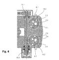
- Fig. 4
- eine Schnittansicht durch den Sockel der Schneidvorrichtung, wobei die Schnittebene entlang der Längsachse der Schnecke verläuft und rechtwinklig zur Längsachse des Arms der Schneidvorrichtung ausgerichtet ist.
- Fig. 1
- a perspective view of a front side of an inventive cutting device for a cross-wire feed,
- Fig. 2
- a view of a rear side of the cutting device
FIG. 1 . - Fig. 3
- a perspective view of the back of the cutting device, wherein some outer parts are not shown, so that the drive of the inventive cutting device is visible, and
- Fig. 4
- a sectional view through the base of the cutting device, wherein the cutting plane along the longitudinal axis of the screw and is aligned at right angles to the longitudinal axis of the arm of the cutting device.
Grundsätzlich sind in den Figuren gleiche Teile mit gleichen Bezugszeichen versehen.Basically, the same parts are provided with the same reference numerals in the figures.
Maschinell hergestellte Gitter aus Draht werden üblicherweise aus Längsdrähten und Querdrähten gebildet. Eine Maschine zur Herstellung eines solchen Gitters umfasst eine Schweissanlage, eine Längsdraht-Zuführeinrichtung zum Zuführen der Längsdrähte zur Schweissanlage und eine Querdraht-Zuführeinrichtung zum Zuführen der Querdrähte zur Schweissanlage.
Die in
Der Verstellmechanismus 5 umfasst dabei zwei Schnittbüchsen 6.1, 6.2, die je drei Öffnungen in der Form von Bohrungen 7.1 - 7.6 aufweisen (vgl. auch
Über einen Teilbereich der axialen Länge der Schnittbüchsen 6.1, 6.2 erstreckt sich je ein Schneckenrad 19.1, 19.2, ersichtlich in
In
Der Schneidmechanismus 4 der Schneideinheit 2 ist in
Wie in
Wie erwähnt, sind die Schnittbüchsen 6.1, 6.2 je drehbar im Sockel 18 des Arms 3 gelagert. Beide Schnittbüchsen 6.1, 6.2 weisen je eine Bearbeitungsposition auf, in welcher sich jeweils eine Bohrung 7.1 - 7.6 der Schnittbüchsen 6.1, 6.2 in der Bearbeitungsposition direkt vor je einer Schneidkante 16.1, 16.2 des jeweiligen Messers 15.1, 15.2 befindet. Ein durch diese Bohrung 7.1 - 7.6 geführter Draht, welcher auf der Vorderseite des Arms 3 aus der Bohrung 7.1 - 7.6 herausragt, ist durch die Schneidkante 16.1, 16.2 des Messers 15.1, 15.2 abscherbar. Das Abscheren geschieht, indem der Messerträger 14 mit den Messern 15.1, 15.2 relativ zum Arm 3 horizontal nach vorne zum freien Ende des Arms 3 hin verschoben wird. Ist der Draht abgeschert, wird der Messerträger 14 wieder nach hinten zurückgezogen. Der Verstellweg, entlang dem der Messerträger 14 mit den Messern 15.1, 15.2 verschiebbar ist, kann dabei in beide Richtungen begrenzt und an den Querschnitt des abzuscherenden Drahts angepasst werden.As mentioned, the cutting bushes 6.1, 6.2 are each rotatably mounted in the
Um einen Querdraht mit einem anderen Durchmesser abzuscheren, wird der Servomotor 9 betätigt, der über den Zahnriemen 10 und das Schneckengetriebe die Schnittbüchsen 6.1, 6.2 dreht, bis sich die gewünschte Bohrung 7.1 - 7.6 in der Bearbeitungsposition befindet.In order to shear off a transverse wire with a different diameter, the
Um die Montage der Schnecke 11 zu vereinfachen, wird die Schnecke 11 so hergestellt, dass der obere Teil 12.1 der Schnecke relativ zum zweiten Teil der Schnecke 12.2 verdrehbar ist. Dadurch kann bei der Montage der Schneckenräder 6.1, 6.2 beispielsweise zuerst das obere Schneckenrad der oberen Schnittbüchse 6.1 montiert und anschliessend das zweite Schneckenrad der unteren Schnittbüchse 6.2 montiert werden. Der obere Teil 12.1 und der untere Teil 12.2 sind am besten in
Die Erfindung ist nicht auf das beschriebene Ausführungsbeispiel beschränkt. So kann beispielsweise die Schneideinheit nicht an einem Arm angeordnet sondern an einer anderen Vorrichtung befestigt sein. Auch kann der Verstellmechanismus mit einem anderen als mit dem beschriebenen Schneidmechanismus verwendet werden. So muss der Schneidmechanismus nicht zwingend einen Messerträger und zwei Messer aufweisen, sondern kann beispielsweise nur ein Messer umfassen, welches für beide Schnittbüchsen einsetzbar ist. Zudem muss die Schneideinheit auch nicht zwei Schnittbüchsen aufweisen, sondern kann nur eine oder mehr als zwei Schnittbüchsen umfassen. Die Schnittbüchsen müssen nicht zwingend als Zylinder ausgeführt sein und können zudem anstelle drehbar auch verschiebbar in einer Lagerung gehalten sein.The invention is not limited to the embodiment described. For example, the cutting unit can not be arranged on an arm but attached to another device. Also, the adjustment mechanism may be used with other than the described cutting mechanism. Thus, the cutting mechanism does not necessarily have a knife carrier and two knives, but may for example comprise only one knife, which can be used for both cutting boxes. In addition, the cutting unit also does not have to have two cutting bushes, but may comprise only one or more than two cutting bushes. The cut rifles need not necessarily be designed as a cylinder and can also be held instead of rotatable and displaceable in a storage.
Zusammenfassend ist festzustellen, dass eine kompakte Schneidvorrichtung geschaffen wurde, mit welcher Draht mit unterschiedlichen Durchmessern effizient und sauber geschnitten werden kann.In summary, it has been found that a compact cutting device has been created, with which wire with different diameters can be cut efficiently and cleanly.
Claims (14)
Priority Applications (1)
| Application Number | Priority Date | Filing Date | Title |
|---|---|---|---|
| EP16188583.5A EP3292933B1 (en) | 2016-09-13 | 2016-09-13 | Cutting device |
Applications Claiming Priority (1)
| Application Number | Priority Date | Filing Date | Title |
|---|---|---|---|
| EP16188583.5A EP3292933B1 (en) | 2016-09-13 | 2016-09-13 | Cutting device |
Publications (2)
| Publication Number | Publication Date |
|---|---|
| EP3292933A1 true EP3292933A1 (en) | 2018-03-14 |
| EP3292933B1 EP3292933B1 (en) | 2022-01-19 |
Family
ID=56958752
Family Applications (1)
| Application Number | Title | Priority Date | Filing Date |
|---|---|---|---|
| EP16188583.5A Active EP3292933B1 (en) | 2016-09-13 | 2016-09-13 | Cutting device |
Country Status (1)
| Country | Link |
|---|---|
| EP (1) | EP3292933B1 (en) |
Citations (4)
| Publication number | Priority date | Publication date | Assignee | Title |
|---|---|---|---|---|
| CH102802A (en) * | 1922-11-01 | 1924-01-02 | Zaugg Otto | Scissors. |
| US4228585A (en) * | 1979-01-29 | 1980-10-21 | Nelson Wilbur C | Animal nail clipper |
| US5988027A (en) * | 1997-05-14 | 1999-11-23 | Lenox - Maclaren | Surgical rod cutter |
| EP1123174B1 (en) | 1999-08-24 | 2004-09-22 | EVG Entwicklungs- u. Verwertungs- Gesellschaft m.b.H. | Installation for separating elements from steel sections |
-
2016
- 2016-09-13 EP EP16188583.5A patent/EP3292933B1/en active Active
Patent Citations (4)
| Publication number | Priority date | Publication date | Assignee | Title |
|---|---|---|---|---|
| CH102802A (en) * | 1922-11-01 | 1924-01-02 | Zaugg Otto | Scissors. |
| US4228585A (en) * | 1979-01-29 | 1980-10-21 | Nelson Wilbur C | Animal nail clipper |
| US5988027A (en) * | 1997-05-14 | 1999-11-23 | Lenox - Maclaren | Surgical rod cutter |
| EP1123174B1 (en) | 1999-08-24 | 2004-09-22 | EVG Entwicklungs- u. Verwertungs- Gesellschaft m.b.H. | Installation for separating elements from steel sections |
Also Published As
| Publication number | Publication date |
|---|---|
| EP3292933B1 (en) | 2022-01-19 |
Similar Documents
| Publication | Publication Date | Title |
|---|---|---|
| CH659203A5 (en) | CUTTING MACHINE. | |
| DE102015118200A1 (en) | PRESSING DEVICE WITH ADJUSTMENT MECHANISM | |
| DE3123183C2 (en) | ||
| DE2823765A1 (en) | DEVICE FOR CUTTING PIPES | |
| DE4040659C1 (en) | Metal spring coiling machine - incorporates wire feed, coiling tools and cutter | |
| DE4236347C2 (en) | Rip cutter | |
| EP0602594B1 (en) | Device for trimming a flat product, particularly a multi-layer printed product | |
| EP0473036B1 (en) | Wire bending machine for insulated wire | |
| DE102004013972A1 (en) | Device for producing cigarettes | |
| DE4138896C2 (en) | ||
| DE3332559A1 (en) | ARMING DEVICE FOR THE CUTTER CYLINDER OF A HARVESTING MACHINE | |
| EP3292933B1 (en) | Cutting device | |
| DE2711557C2 (en) | Length stop for scissors | |
| DE1552141C3 (en) | Wire bending device for forming hooks, in particular on helical springs | |
| DE1810052B2 (en) | Device for cutting through continuously fed pipes | |
| DE102019102404B4 (en) | Device for cutting a hose provided with a reinforcing element | |
| DE2128218A1 (en) | Method and device for trim men in the blow molding manufactured art fabric objects | |
| DE2108338B2 (en) | Cutting device for dividing continuously delivered strands of material | |
| DE1627162C3 (en) | Device for processing the head part of rails | |
| EP3172995A1 (en) | Device for peeling fruit and vegetables | |
| DE4222310A1 (en) | Device for separating one or more strands of molten glass into individual glass items | |
| DE2814182A1 (en) | DEVICE FOR CUTTING THE CONNECTION WIRES FROM ELECTRICAL COMPONENTS | |
| EP2740556B1 (en) | Cutting device comprising rollers for supporting workpieces, such as bars, pipes and the like | |
| DE3428413A1 (en) | DEVICE FOR CUTTING GLASS FLOWERS | |
| DE1552622B2 (en) | Flying scissors |
Legal Events
| Date | Code | Title | Description |
|---|---|---|---|
| PUAI | Public reference made under article 153(3) epc to a published international application that has entered the european phase |
Free format text: ORIGINAL CODE: 0009012 |
|
| STAA | Information on the status of an ep patent application or granted ep patent |
Free format text: STATUS: THE APPLICATION HAS BEEN PUBLISHED |
|
| AK | Designated contracting states |
Kind code of ref document: A1 Designated state(s): AL AT BE BG CH CY CZ DE DK EE ES FI FR GB GR HR HU IE IS IT LI LT LU LV MC MK MT NL NO PL PT RO RS SE SI SK SM TR |
|
| AX | Request for extension of the european patent |
Extension state: BA ME |
|
| STAA | Information on the status of an ep patent application or granted ep patent |
Free format text: STATUS: REQUEST FOR EXAMINATION WAS MADE |
|
| 17P | Request for examination filed |
Effective date: 20180507 |
|
| RBV | Designated contracting states (corrected) |
Designated state(s): AL AT BE BG CH CY CZ DE DK EE ES FI FR GB GR HR HU IE IS IT LI LT LU LV MC MK MT NL NO PL PT RO RS SE SI SK SM TR |
|
| STAA | Information on the status of an ep patent application or granted ep patent |
Free format text: STATUS: EXAMINATION IS IN PROGRESS |
|
| 17Q | First examination report despatched |
Effective date: 20201026 |
|
| STAA | Information on the status of an ep patent application or granted ep patent |
Free format text: STATUS: EXAMINATION IS IN PROGRESS |
|
| GRAP | Despatch of communication of intention to grant a patent |
Free format text: ORIGINAL CODE: EPIDOSNIGR1 |
|
| STAA | Information on the status of an ep patent application or granted ep patent |
Free format text: STATUS: GRANT OF PATENT IS INTENDED |
|
| INTG | Intention to grant announced |
Effective date: 20211108 |
|
| GRAS | Grant fee paid |
Free format text: ORIGINAL CODE: EPIDOSNIGR3 |
|
| STAA | Information on the status of an ep patent application or granted ep patent |
Free format text: STATUS: GRANT OF PATENT IS INTENDED |
|
| GRAA | (expected) grant |
Free format text: ORIGINAL CODE: 0009210 |
|
| STAA | Information on the status of an ep patent application or granted ep patent |
Free format text: STATUS: THE PATENT HAS BEEN GRANTED |
|
| AK | Designated contracting states |
Kind code of ref document: B1 Designated state(s): AL AT BE BG CH CY CZ DE DK EE ES FI FR GB GR HR HU IE IS IT LI LT LU LV MC MK MT NL NO PL PT RO RS SE SI SK SM TR |
|
| REG | Reference to a national code |
Ref country code: GB Ref legal event code: FG4D Free format text: NOT ENGLISH |
|
| REG | Reference to a national code |
Ref country code: CH Ref legal event code: EP |
|
| REG | Reference to a national code |
Ref country code: DE Ref legal event code: R096 Ref document number: 502016014417 Country of ref document: DE |
|
| REG | Reference to a national code |
Ref country code: AT Ref legal event code: REF Ref document number: 1463498 Country of ref document: AT Kind code of ref document: T Effective date: 20220215 |
|
| REG | Reference to a national code |
Ref country code: IE Ref legal event code: FG4D Free format text: LANGUAGE OF EP DOCUMENT: GERMAN |
|
| REG | Reference to a national code |
Ref country code: LT Ref legal event code: MG9D |
|
| REG | Reference to a national code |
Ref country code: NL Ref legal event code: MP Effective date: 20220119 |
|
| PG25 | Lapsed in a contracting state [announced via postgrant information from national office to epo] |
Ref country code: NL Free format text: LAPSE BECAUSE OF FAILURE TO SUBMIT A TRANSLATION OF THE DESCRIPTION OR TO PAY THE FEE WITHIN THE PRESCRIBED TIME-LIMIT Effective date: 20220119 |
|
| PG25 | Lapsed in a contracting state [announced via postgrant information from national office to epo] |
Ref country code: SE Free format text: LAPSE BECAUSE OF FAILURE TO SUBMIT A TRANSLATION OF THE DESCRIPTION OR TO PAY THE FEE WITHIN THE PRESCRIBED TIME-LIMIT Effective date: 20220119 Ref country code: RS Free format text: LAPSE BECAUSE OF FAILURE TO SUBMIT A TRANSLATION OF THE DESCRIPTION OR TO PAY THE FEE WITHIN THE PRESCRIBED TIME-LIMIT Effective date: 20220119 Ref country code: PT Free format text: LAPSE BECAUSE OF FAILURE TO SUBMIT A TRANSLATION OF THE DESCRIPTION OR TO PAY THE FEE WITHIN THE PRESCRIBED TIME-LIMIT Effective date: 20220519 Ref country code: NO Free format text: LAPSE BECAUSE OF FAILURE TO SUBMIT A TRANSLATION OF THE DESCRIPTION OR TO PAY THE FEE WITHIN THE PRESCRIBED TIME-LIMIT Effective date: 20220419 Ref country code: LT Free format text: LAPSE BECAUSE OF FAILURE TO SUBMIT A TRANSLATION OF THE DESCRIPTION OR TO PAY THE FEE WITHIN THE PRESCRIBED TIME-LIMIT Effective date: 20220119 Ref country code: HR Free format text: LAPSE BECAUSE OF FAILURE TO SUBMIT A TRANSLATION OF THE DESCRIPTION OR TO PAY THE FEE WITHIN THE PRESCRIBED TIME-LIMIT Effective date: 20220119 Ref country code: ES Free format text: LAPSE BECAUSE OF FAILURE TO SUBMIT A TRANSLATION OF THE DESCRIPTION OR TO PAY THE FEE WITHIN THE PRESCRIBED TIME-LIMIT Effective date: 20220119 Ref country code: BG Free format text: LAPSE BECAUSE OF FAILURE TO SUBMIT A TRANSLATION OF THE DESCRIPTION OR TO PAY THE FEE WITHIN THE PRESCRIBED TIME-LIMIT Effective date: 20220419 |
|
| PG25 | Lapsed in a contracting state [announced via postgrant information from national office to epo] |
Ref country code: PL Free format text: LAPSE BECAUSE OF FAILURE TO SUBMIT A TRANSLATION OF THE DESCRIPTION OR TO PAY THE FEE WITHIN THE PRESCRIBED TIME-LIMIT Effective date: 20220119 Ref country code: LV Free format text: LAPSE BECAUSE OF FAILURE TO SUBMIT A TRANSLATION OF THE DESCRIPTION OR TO PAY THE FEE WITHIN THE PRESCRIBED TIME-LIMIT Effective date: 20220119 Ref country code: GR Free format text: LAPSE BECAUSE OF FAILURE TO SUBMIT A TRANSLATION OF THE DESCRIPTION OR TO PAY THE FEE WITHIN THE PRESCRIBED TIME-LIMIT Effective date: 20220420 Ref country code: FI Free format text: LAPSE BECAUSE OF FAILURE TO SUBMIT A TRANSLATION OF THE DESCRIPTION OR TO PAY THE FEE WITHIN THE PRESCRIBED TIME-LIMIT Effective date: 20220119 |
|
| PG25 | Lapsed in a contracting state [announced via postgrant information from national office to epo] |
Ref country code: IS Free format text: LAPSE BECAUSE OF FAILURE TO SUBMIT A TRANSLATION OF THE DESCRIPTION OR TO PAY THE FEE WITHIN THE PRESCRIBED TIME-LIMIT Effective date: 20220519 |
|
| REG | Reference to a national code |
Ref country code: DE Ref legal event code: R097 Ref document number: 502016014417 Country of ref document: DE |
|
| PG25 | Lapsed in a contracting state [announced via postgrant information from national office to epo] |
Ref country code: SM Free format text: LAPSE BECAUSE OF FAILURE TO SUBMIT A TRANSLATION OF THE DESCRIPTION OR TO PAY THE FEE WITHIN THE PRESCRIBED TIME-LIMIT Effective date: 20220119 Ref country code: SK Free format text: LAPSE BECAUSE OF FAILURE TO SUBMIT A TRANSLATION OF THE DESCRIPTION OR TO PAY THE FEE WITHIN THE PRESCRIBED TIME-LIMIT Effective date: 20220119 Ref country code: RO Free format text: LAPSE BECAUSE OF FAILURE TO SUBMIT A TRANSLATION OF THE DESCRIPTION OR TO PAY THE FEE WITHIN THE PRESCRIBED TIME-LIMIT Effective date: 20220119 Ref country code: EE Free format text: LAPSE BECAUSE OF FAILURE TO SUBMIT A TRANSLATION OF THE DESCRIPTION OR TO PAY THE FEE WITHIN THE PRESCRIBED TIME-LIMIT Effective date: 20220119 Ref country code: DK Free format text: LAPSE BECAUSE OF FAILURE TO SUBMIT A TRANSLATION OF THE DESCRIPTION OR TO PAY THE FEE WITHIN THE PRESCRIBED TIME-LIMIT Effective date: 20220119 Ref country code: CZ Free format text: LAPSE BECAUSE OF FAILURE TO SUBMIT A TRANSLATION OF THE DESCRIPTION OR TO PAY THE FEE WITHIN THE PRESCRIBED TIME-LIMIT Effective date: 20220119 |
|
| PLBE | No opposition filed within time limit |
Free format text: ORIGINAL CODE: 0009261 |
|
| STAA | Information on the status of an ep patent application or granted ep patent |
Free format text: STATUS: NO OPPOSITION FILED WITHIN TIME LIMIT |
|
| PG25 | Lapsed in a contracting state [announced via postgrant information from national office to epo] |
Ref country code: AL Free format text: LAPSE BECAUSE OF FAILURE TO SUBMIT A TRANSLATION OF THE DESCRIPTION OR TO PAY THE FEE WITHIN THE PRESCRIBED TIME-LIMIT Effective date: 20220119 |
|
| 26N | No opposition filed |
Effective date: 20221020 |
|
| PG25 | Lapsed in a contracting state [announced via postgrant information from national office to epo] |
Ref country code: SI Free format text: LAPSE BECAUSE OF FAILURE TO SUBMIT A TRANSLATION OF THE DESCRIPTION OR TO PAY THE FEE WITHIN THE PRESCRIBED TIME-LIMIT Effective date: 20220119 |
|
| PG25 | Lapsed in a contracting state [announced via postgrant information from national office to epo] |
Ref country code: MC Free format text: LAPSE BECAUSE OF FAILURE TO SUBMIT A TRANSLATION OF THE DESCRIPTION OR TO PAY THE FEE WITHIN THE PRESCRIBED TIME-LIMIT Effective date: 20220119 |
|
| GBPC | Gb: european patent ceased through non-payment of renewal fee |
Effective date: 20220913 |
|
| REG | Reference to a national code |
Ref country code: BE Ref legal event code: MM Effective date: 20220930 |
|
| P01 | Opt-out of the competence of the unified patent court (upc) registered |
Effective date: 20230515 |
|
| PG25 | Lapsed in a contracting state [announced via postgrant information from national office to epo] |
Ref country code: LU Free format text: LAPSE BECAUSE OF NON-PAYMENT OF DUE FEES Effective date: 20220913 |
|
| PG25 | Lapsed in a contracting state [announced via postgrant information from national office to epo] |
Ref country code: IE Free format text: LAPSE BECAUSE OF NON-PAYMENT OF DUE FEES Effective date: 20220913 Ref country code: FR Free format text: LAPSE BECAUSE OF NON-PAYMENT OF DUE FEES Effective date: 20220930 |
|
| PG25 | Lapsed in a contracting state [announced via postgrant information from national office to epo] |
Ref country code: BE Free format text: LAPSE BECAUSE OF NON-PAYMENT OF DUE FEES Effective date: 20220930 |
|
| PG25 | Lapsed in a contracting state [announced via postgrant information from national office to epo] |
Ref country code: GB Free format text: LAPSE BECAUSE OF NON-PAYMENT OF DUE FEES Effective date: 20220913 |
|
| PGFP | Annual fee paid to national office [announced via postgrant information from national office to epo] |
Ref country code: AT Payment date: 20230921 Year of fee payment: 8 |
|
| PGFP | Annual fee paid to national office [announced via postgrant information from national office to epo] |
Ref country code: DE Payment date: 20230823 Year of fee payment: 8 |
|
| PGFP | Annual fee paid to national office [announced via postgrant information from national office to epo] |
Ref country code: IT Payment date: 20230927 Year of fee payment: 8 Ref country code: CH Payment date: 20231001 Year of fee payment: 8 |
|
| PG25 | Lapsed in a contracting state [announced via postgrant information from national office to epo] |
Ref country code: HU Free format text: LAPSE BECAUSE OF FAILURE TO SUBMIT A TRANSLATION OF THE DESCRIPTION OR TO PAY THE FEE WITHIN THE PRESCRIBED TIME-LIMIT; INVALID AB INITIO Effective date: 20160913 |
|
| PG25 | Lapsed in a contracting state [announced via postgrant information from national office to epo] |
Ref country code: CY Free format text: LAPSE BECAUSE OF FAILURE TO SUBMIT A TRANSLATION OF THE DESCRIPTION OR TO PAY THE FEE WITHIN THE PRESCRIBED TIME-LIMIT Effective date: 20220119 |