EP1123174B1 - Installation for separating elements from steel sections - Google Patents
Installation for separating elements from steel sections Download PDFInfo
- Publication number
- EP1123174B1 EP1123174B1 EP00951087A EP00951087A EP1123174B1 EP 1123174 B1 EP1123174 B1 EP 1123174B1 EP 00951087 A EP00951087 A EP 00951087A EP 00951087 A EP00951087 A EP 00951087A EP 1123174 B1 EP1123174 B1 EP 1123174B1
- Authority
- EP
- European Patent Office
- Prior art keywords
- cutting
- control device
- controlled
- cutting device
- blade
- Prior art date
- Legal status (The legal status is an assumption and is not a legal conclusion. Google has not performed a legal analysis and makes no representation as to the accuracy of the status listed.)
- Expired - Lifetime
Links
Images
Classifications
-
- B—PERFORMING OPERATIONS; TRANSPORTING
- B21—MECHANICAL METAL-WORKING WITHOUT ESSENTIALLY REMOVING MATERIAL; PUNCHING METAL
- B21F—WORKING OR PROCESSING OF METAL WIRE
- B21F23/00—Feeding wire in wire-working machines or apparatus
- B21F23/002—Feeding means specially adapted for handling various diameters of wire or rod
-
- B—PERFORMING OPERATIONS; TRANSPORTING
- B21—MECHANICAL METAL-WORKING WITHOUT ESSENTIALLY REMOVING MATERIAL; PUNCHING METAL
- B21F—WORKING OR PROCESSING OF METAL WIRE
- B21F11/00—Cutting wire
-
- B—PERFORMING OPERATIONS; TRANSPORTING
- B23—MACHINE TOOLS; METAL-WORKING NOT OTHERWISE PROVIDED FOR
- B23D—PLANING; SLOTTING; SHEARING; BROACHING; SAWING; FILING; SCRAPING; LIKE OPERATIONS FOR WORKING METAL BY REMOVING MATERIAL, NOT OTHERWISE PROVIDED FOR
- B23D23/00—Machines or devices for shearing or cutting profiled stock
-
- B—PERFORMING OPERATIONS; TRANSPORTING
- B23—MACHINE TOOLS; METAL-WORKING NOT OTHERWISE PROVIDED FOR
- B23D—PLANING; SLOTTING; SHEARING; BROACHING; SAWING; FILING; SCRAPING; LIKE OPERATIONS FOR WORKING METAL BY REMOVING MATERIAL, NOT OTHERWISE PROVIDED FOR
- B23D33/00—Accessories for shearing machines or shearing devices
- B23D33/006—Accessories for shearing machines or shearing devices for obtaining pieces of a predetermined length, e.g. control arrangements
Definitions
- the invention relates to a system for separating elements selectable length of several, in particular wire, tape and strip-like strands of steel, with at least a device for the continuous advancement of the material strands at high speed, with at least one stationary arranged, having at least one movable knife Cutter.
- the object of the invention is the disadvantages described to avoid and an installation of the type specified in the introduction create that makes it possible with structurally simple, stationary Cutting devices without much control effort simultaneously by several continuously at high speed cut off the material strands supplied.
- the system according to the invention is characterized in that at least one stationary cutting device is provided for each strand of material is that any cutter for quick severing of elements of the same and / or different lengths individually from a central servo valve connected to the control device is controllable, and that the stroke of at least one knife the cutting device depending on the material thickness of the strand of material to be cut is selected.
- the controllable by the servo valve controllable by the control device is, and it becomes the stroke of the movable knife a displacement sensor connected to the control device.
- To select the material strands is preferably one of the control device controllable with the central servo valve and the drive devices of the cutting devices connected distributor provided.
- the distributor shows pro Cutting device each controllable by the control device Directional control valve on.
- the cutting devices with their directional valves are useful can be grouped together, each group of directional valves has a common manifold and the groups can be controlled by at least one servo valve.
- each feed device at least one corresponding to the directions of the double arrow feed wheel that can be lifted from the material strand.
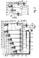
- the system shown in Fig. 1 is used for separation several elements of selectable length from continuous to high Speed fed according to the flow direction P1
- Material strands M made of steel.
- the material strands M can Framework of the invention made of wire, ribbon and strip-shaped material exist and have any cross-sectional shape.
- the material can be hot-rolled and / or cold-formed steel.
- the surface of the material strands M can be smooth or, as is usual with reinforcement steel, ribbed his.
- the system can, for example, within the scope of the invention belong to a straightening and cutting system for reinforcing steel, whereby the material strands M preferably have different diameters and / or material properties.
- the system according to the invention has one for each strand of material M. stationary cutting device 1 and a feed device 2 which, for the sake of clarity, is only shown schematically and is shown in more detail in Fig. 2.
- a single central feed device to be provided for all strands of material M that the material strands via a correspondingly designed device M feeds the individual cutting devices 1.
- a further cutting device 1 ' arranged at a greater distance from the first cutting device 1 is.
- the second cutting device 1 is then always used when necessary on two separate rooms Have separate items available and if an exact positioning of the elements due to the high Feed speed of the strand of material too imprecise and is complex.
- the creation of cross and longitudinal wires for one Wire mesh mat welding machine is a typical application this embodiment.
- the system shown also has a control device 3, a central servo valve 4 and for each cutting device 1 a directional valve 5, with all directional valves 5 on a common manifold 6 are arranged.
- a further directional valve 5 ' is provided, with all directional valves 5 'are arranged on a manifold 6'.
- Each cutting device 1, 1 ' has a fixed knife 7 and a movable according to the directions of the double arrow P2 Knife 8 for separating the element from the strand of material M.
- the required movement of the knife 8 is with Helped by a working cylinder 9, the hydraulic lines 10 or 10 'is connected to the directional control valve 5 or 5'.
- a Signal line 13 or 13 ' connects each displacement sensor 12 to the control device 3 and a control line 14 provides the Connection between the control device 3 and the central Servo valve 4 ago.
- it is possible to Movement of the movable knife 8 by equivalent devices, for example by an eccentric drive.
- Each directional valve 5 or 5 ' is via the connection plate 6 or 6 'through hydraulic lines 15 or 15' with the servo valve 4 connected.
- the directional control valves 5 and 5 ' are via control lines 16 or 16 'controlled by the control device 3.
- Control lines 17 also connect the control device 3 with the feed devices 2 or a central feed device.
- the feed device shown schematically in Fig. 2 2 has a feed wheel which can be driven in the direction of the arrow P3 18 and a drivable according to the direction of arrow P3 ' Feed wheel 19, which with the help of a pressure cylinder 20 movable according to the directions of the double arrow P4 is.
- the pressure cylinder 20 is via hydraulic lines 21 connected to a fast switching valve 22, which via the Control line 17 is controlled by the control device 3.
- each feed device 2 can be equipped with a Length measuring device may be provided.
- control device 3 controls the central servo valve 4 in Dependence on the feed rate of the corresponding Material strand M and the desired element length at and selects the corresponding directional valve 5 or 5 'of the associated one Material strand M before.
- the movable knife 8 moves in the corresponding one Direction of the double arrow P2, creating the element is separated from the strand of material M.
- the displacement sensor 12 measures the stroke movement of the knife 8 and gives a corresponding one Signal to the control device 3 from the lifting movement according to the material thickness of the material strand M. minimize.
- the fast switching valve 22 for the pressure cylinder 20 of the feed device 2 is controlled in such a way that the ventable feed wheel 19 briefly the material strand M relieved and thus minimized traces of friction on the strand of material M. become. This procedure can lead to a material jam during of cutting can be avoided.
- front cutters 1 of all strands of material M and rear cutting devices 1 'of all material strands M each summarize in groups.
- Each servo valve 4 will in all exemplary embodiments by the central control device 3 controlled accordingly.
Landscapes
- Engineering & Computer Science (AREA)
- Mechanical Engineering (AREA)
- Shearing Machines (AREA)
- Wire Processing (AREA)
- Solid-Sorbent Or Filter-Aiding Compositions (AREA)
- Combined Means For Separation Of Solids (AREA)
- Coating With Molten Metal (AREA)
- Superconductors And Manufacturing Methods Therefor (AREA)
Abstract
Description
Die Erfindung betrifft eine Anlage zum Abtrennen von Elementen wählbarer Länge von mehreren, insbesondere draht-, bandund streifenförmigen Materialsträngen aus Stahl, mit zumindest einer Einrichtung zum kontinuierlichen Vorschieben der Materialstränge mit hoher Geschwindigkeit, mit zumindest einer stationär angeordneten, zumindest ein bewegliches Messer aufweisende Schneideinrichtung.The invention relates to a system for separating elements selectable length of several, in particular wire, tape and strip-like strands of steel, with at least a device for the continuous advancement of the material strands at high speed, with at least one stationary arranged, having at least one movable knife Cutter.
Es sind Schneidvorrichtungen zum Abtrennen von Stäben wählbarer Länge von einem kontinuierlich mit hoher Geschwindigkeit zugeführten Materialstrang bekannt, bei welchen die Schneidvorrichtungen aus fliegenden Scheren bestehen. Hierbei muß die Vorschubbewegung der Scheren der Vorschubgeschwindigkeit des Materialstranges genau angepaßt werden. Nachteilig bei diesen bekannten Vorrichtungen ist, daß sie aufgrund der erforderlichen Bewegungen konstruktiv sehr aufwendig sind und daher einen großen Platzbedarf haben. Durch diesen großen konstruktiven Aufwand ist es unwirtschaftlich, bei mehradrigen Anlagen alle Materialstränge mit fliegenden Scheren auszurüsten. Lediglich zwei nebeneinander liegende Materialstränge mit gleichem Durchmesser und gleicher Vorschubgeschwindigkeit können gleichzeitig von einer Schere bearbeitet werden. Ein weiter Nachteil besteht darin, daß ein hoher Steuerungsaufwand erforderlich ist, um die Bewegungsabläufe genau aufeinander abzustimmen.They are cutting devices for cutting bars selectable length of one continuously at high speed supplied strand of material known, in which the Cutting devices consist of flying scissors. in this connection the feed movement of the scissors must match the feed speed of the strand of material can be adjusted exactly. A disadvantage of these known devices is that because of the required Movements are very expensive to construct and therefore have a large space requirement. Because of this great constructive It is uneconomical for multi-core systems Equip all strands of material with flying shears. Only two adjacent strands of material with the same Diameter and the same feed speed can be used simultaneously processed by scissors. Another disadvantage is that a high control effort is required is to precisely coordinate the movements.
Aufgabe der Erfindung ist es, die geschilderten Nachteile zu vermeiden und eine Anlage der einleitend angegebenen Art zu schaffen, die es ermöglicht, mit konstruktiv einfachen, stationären Schneideinrichtungen ohne großen Steuerungsaufwand gleichzeitig von mehreren kontinuierlich mit hoher Geschwindigkeit zugeführten Materialsträngen Elemente wählbarer Länge abzutrennen.The object of the invention is the disadvantages described to avoid and an installation of the type specified in the introduction create that makes it possible with structurally simple, stationary Cutting devices without much control effort simultaneously by several continuously at high speed cut off the material strands supplied.
Die erfindungsgemäße Anlage zeichnet sich dadurch aus, daß für jeden Materialstrang zumindest eine stationär angeordnete Schneideinrichtung vorgesehen ist, daß jede Schneideinrichtung zum schnellen Abtrennen von Elementen gleicher und/oder verschiedener Länge einzeln von einem zentralen, mit der Steuereinrichtung verbundenem Servoventil ansteuerbar ist, und daß der Hub zumindest eines Messers der Schneideinrichtung in Abhängigkeit von der Materialstärke des zu durchtrennenden Materialstranges gewählt wird.The system according to the invention is characterized in that at least one stationary cutting device is provided for each strand of material is that any cutter for quick severing of elements of the same and / or different lengths individually from a central servo valve connected to the control device is controllable, and that the stroke of at least one knife the cutting device depending on the material thickness of the strand of material to be cut is selected.
Nach einem weiteren Merkmal der Erfindung ist zum Ausführen der Schnellen Schneidbewegung des beweglichen Messers eine Antriebseinrichtung zum Bewegen des Messers vorgesehen, die durch das von der Steuereinrichtung steuerbare Servoventil ansteuerbar ist, und es wird der Hub des beweglichen Messers mit einem mit der Steuereinrichtung verbundenem Wegaufnehmer erfaßt.According to another feature of the invention is to be carried out the fast cutting movement of the movable knife Drive device provided for moving the knife, the controllable by the servo valve controllable by the control device is, and it becomes the stroke of the movable knife a displacement sensor connected to the control device.
Vorzugsweise ist zum Auswählen der Materialstränge ein von der Steuereinrichtung ansteuerbarer, mit dem zentralen Servoventil und den Antriebseinrichtungen der Schneideinrichtungen verbundener Verteiler vorgesehen. Dabei weist der Verteiler pro Schneideinrichtung je ein von der Steuereinrichtung ansteuerbares Wegeventil auf.To select the material strands is preferably one of the control device controllable with the central servo valve and the drive devices of the cutting devices connected distributor provided. The distributor shows pro Cutting device each controllable by the control device Directional control valve on.
Zweckmäßig sind die Schneideinrichtungen mit ihren Wegeventilen gruppenweise zusammenfaßbar, wobei jede Gruppe von Wegeventilen eine gemeinsame Mehrfachanschlußplatte aufweist und die Gruppen von zumindest einem Servoventil ansteuerbar sind.The cutting devices with their directional valves are useful can be grouped together, each group of directional valves has a common manifold and the groups can be controlled by at least one servo valve.
Gemäß einem anderen Merkmal der Erfindung weist zum kurzzeitigen Verlangsamen des Materialstranges jede Vorschubeinrichtung zumindest ein entsprechend den Richtungen des Doppelpfeiles vom Materialstrang lüftbares Vorschubrad auf.According to another feature of the invention points to the short-term Slow down the strand of material each feed device at least one corresponding to the directions of the double arrow feed wheel that can be lifted from the material strand.
Weitere Merkmale und Vorteile der Erfindung werden nachfolgend
an Ausführungsbeispielen unter Bezugnahme auf die
Zeichnungen näher erläutert. Es zeigen:
Die in Fig. 1 dargestellte Anlage dient zum Abtrennen mehrerer Elemente wählbarer Länge von kontinuierlich mit hoher Geschwindigkeit entsprechend der Flußrichtung P1 zugeführten Materialsträngen M aus Stahl. Die Materialstränge M können im Rahmen der Erfindung aus draht-, band- und streifenförmigem Material bestehen und beliebige Querschnittsformen haben. Das Material kann im Rahmen der Erfindung warmgewalzter und/oder kaltverformter Stahl sein. Die Oberfläche der Materialstränge M kann glatt oder, wie bei Bewehrungsstählen üblich, gerippt sein. Die Anlage kann im Rahmen der Erfindung beispielsweise zu einer Richt- und Schneidanlage für Bewehrungsstahl gehören, wobei die Materialstränge M vorzugsweise unterschiedliche Durchmesser und/oder Materialeigenschaften haben können.The system shown in Fig. 1 is used for separation several elements of selectable length from continuous to high Speed fed according to the flow direction P1 Material strands M made of steel. The material strands M can Framework of the invention made of wire, ribbon and strip-shaped material exist and have any cross-sectional shape. The material can be hot-rolled and / or cold-formed steel. The surface of the material strands M can be smooth or, as is usual with reinforcement steel, ribbed his. The system can, for example, within the scope of the invention belong to a straightening and cutting system for reinforcing steel, whereby the material strands M preferably have different diameters and / or material properties.
Die erfindungsgemäße Anlage weist je Materialstrang M eine
stationäre Schneideinrichtung 1 und eine Vorschubeinrichtung 2
auf, welche der besseren Übersicht halber nur schematisch dargestellt
und in Fig. 2 genauer gezeigt ist. Im Rahmen der Erfindung
ist es jedoch auch möglich, eine einzige zentrale Vorschubeinrichtung
für alle Materialstränge M vorzusehen, die
über eine entsprechend ausgestaltete Einrichtung die Materialstränge
M den einzelnen Schneideinrichtungen 1 zuführt. Ferner
ist es möglich, nur einen oder mehrere bzw. alle Materialstränge
M mit einer weiteren Schneideinrichtung 1' zu versehen, die
in einem größeren Abstand zur ersten Schneideinrichtung 1 angeordnet
ist. Die zweite Schneideinrichtung 1' wird immer dann
eingesetzt, wenn es erforderlich ist, an zwei räumlich getrennten
Positionen abgetrennte Elemente zur Verfügung zu haben und
wenn eine exakte Positionierung der Elemente aufgrund der hohen
Vorschubgeschwindigkeit des Materialstranges zu ungenau und
aufwendig ist. Das Erzeugen von Quer- und Längsdrähten für eine
Drahtgittermatten-Schweißmaschine ist ein typischer Anwendungsfall
dieser Ausführungsform.The system according to the invention has one for each strand of material M.
stationary cutting device 1 and a
Die dargestellte Anlage weist außerdem eine Steuereinrichtung
3, ein zentrales Servoventil 4 und für jede Schneideinrichtung
1 ein Wegeventil 5 auf, wobei alle Wegeventile 5 auf
einer gemeinsamen Mehrfachanschlußplatte 6 angeordnet sind. Für
die weiteren Schneideinrichtungen 1' je Materialstrang M ist
jeweils ein weiteres Wegeventil 5' vorgesehen, wobei alle Wegeventile
5' auf einer Mehrfachanschlußplatte 6' angeordnet sind.The system shown also has a
Jede Schneideinrichtung 1, 1' hat ein feststehendes Messer
7 und ein entsprechend den Richtungen des Doppelpfeiles P2 bewegliches
Messer 8 zum Abtrennen des Elementes vom Materialstrang
M. Die erforderliche Bewegung des Messers 8 wird mit
Hilfe eines Arbeitszylinders 9 erzielt, der über Hydraulikleitungen
10 bzw. 10' mit dem Wegeventil 5 bzw. 5' verbunden ist.
Der Hub des Kolbens 11 des Arbeitszylinders 9 und damit der Hub
des beweglichen Messers 8 wird mit Hilfe eines Wegaufnehmers
12, der beispielsweise ein Induktivaufnehmer ist, erfaßt. Eine
Signalleitung 13 bzw. 13' verbindet jeden Wegaufnehmer 12 mit
der Steuereinrichtung 3 und eine Steuerleitung 14 stellt die
Verbindung zwischen der Steuereinrichtung 3 und dem zentralen
Servoventil 4 her. Im Rahmen der Erfindung ist es möglich, die
Bewegung des beweglichen Messers 8 durch äquivalente Vorrichtungen,
beispielsweise durch einen Exzentertrieb zu bewirken.Each cutting device 1, 1 'has a fixed knife
7 and a movable according to the directions of the double arrow P2
Knife 8 for separating the element from the strand of material
M. The required movement of the
Jedes Wegeventil 5 bzw. 5' ist über die Anschlußplatte 6
bzw. 6' durch Hydraulikleitungen 15 bzw. 15' mit dem Servoventil
4 verbunden. Die Wegeventile 5 bzw. 5' werden über Steuerleitungen
16 bzw. 16' von der Steuereinrichtung 3 angesteuert.
Steuerleitungen 17 verbinden die Steuereinrichtung 3 außerdem
mit den Vorschubeinrichtungen 2 bzw. einer zentralen Vorschubeinrichtung.Each
Die in Fig. 2 schematisch dargestellte Vorschubeinrichtung
2 weist ein entsprechend der Pfeilrichtung P3 antreibbares Vorschubrad
18 und ein entsprechend der Pfeilrichtung P3' antreibbares
Vorschubrad 19 auf, welches mit Hilfe eines Anpreßzylinders
20 entsprechend den Richtungen des Doppelpfeiles P4 bewegbar
ist. Der Anpreßzylinder 20 ist über Hydraulikleitungen 21
mit einem schnell schaltenden Ventil 22 verbunden, das über die
Steuerleitung 17 von der Steuereinrichtung 3 angesteuert wird.
Im Rahmen der Erfindung kann jede Vorschubeinrichtung 2 mit einer
Längenmeßeinrichtung versehen sein.The feed device shown schematically in Fig. 2
2 has a feed wheel which can be driven in the direction of the
Die Anlage arbeitet in folgender Weise: The system works in the following way:
Zum Abtrennen eines Elementes von einem Materialstrang M
steuert die Steuereinrichtung 3 das zentrale Servoventil 4 in
Abhängigkeit von der Vorschubgeschwindigkeit des entsprechenden
Materialstranges M und der gewünschten Elementlänge an und
wählt das entsprechende Wegeventil 5 bzw. 5' des zugehörigen
Materialstranges M vor.For separating an element from a strand of material M
the
Zum Schneiden fährt das bewegliche Messer 8 in der entsprechenden
Richtung des Doppelpfeiles P2 aus, wodurch das Element
vom Materialstrang M abgetrennt wird. Der Wegaufnehmer 12
mißt dabei die Hubbewegung des Messers 8 und gibt ein entsprechendes
Signal an die Steuereinrichtung 3 ab, um die Hubbewegung
entsprechend der Materialstärke des Materialstranges M zu
minimieren. Zeitgleich mit dem Schnittsignal wird von der Steuereinrichtung
3 das schnell schaltende Ventil 22 für den Anpreßzylinder
20 der Vorschubeinrichtung 2 derart angesteuert,
daß das lüftbare Vorschubrad 19 kurzzeitig den Materialstrang M
entlastet und damit Reibspuren am Materialstrang M minimiert
werden. Durch diese Vorgangsweise kann ein Materialstau während
des Schneidens vermieden werden.For cutting, the
Bei der erfindungsgemäßen Anlage werden zum Abtrennen von Elementen gleicher Durchmesser und Längen und/oder unterschiedlicher Durchmesser und Längen die Schneideinrichtungen der Materialstränge M gezielt individuell ausgewählt.In the plant according to the invention, for separating Elements of the same diameter and length and / or different Diameters and lengths of the cutting devices of the material strands M specifically selected individually.
Es versteht sich, daß die dargestellten Ausführungsbeispiele im Rahmen des allgemeinen Erfindungsgedankens verschiedentlich, insbesondere hinsichtlich der Ausgestaltung und Ausführung der Schneideinrichtung abgewandelt werden können. Im Rahmen der Erfindung ist es beispielsweise möglich, beide Messer beweglich auszuführen, um damit die Schnittgeschwindigkeit zu erhöhen.It is understood that the illustrated embodiments various within the scope of the general inventive concept, especially with regard to the design and execution the cutting device can be modified. in the Within the scope of the invention it is possible, for example, to use both knives flexible to achieve the cutting speed to increase.
Des weiteren ist es im Rahmen der Erfindung möglich, zur
Erhöhung der Schnittleistung und zur besseren Anpassung an
stark unterschiedliche Vorschubgeschwindigkeiten der Materialstränge
M die Schneideinrichtungen 1; 1' mit ihren Wegeventilen
5; 5' gruppenweise zusammenzufassen, wobei jede Gruppe von Wegeventilen
5, 5' auf einer gemeinsamen Mehrfachanschlußplatte
6, 6' angeordnet ist und entweder ein Servoventil 4 für alle
Gruppen oder zumindest ein Servoventil 4 pro Gruppe vorgesehen
ist. Des weiteren ist es im Rahmen der Erfindung möglich, die
vorderen Schneideinrichtungen 1 aller Materialstränge M und die
hinteren Schneideinrichtungen 1' aller Materialstränge M jeweils
gruppenweise zusammenzufassen. Jedes Servoventil 4 wird
in allen Ausführungsbeispielen von der zentralen Steuereinrichtung
3 entsprechend angesteuert.Furthermore, it is possible within the scope of the invention to
Increase in cutting performance and for better adjustment
very different feed speeds of the material strands
M the cutting devices 1; 1 'with their
Claims (8)
- Apparatus for separating elements of selectable length from several, in particular wire-, belt- and strip-shaped strings of steel material, with at least one device for continuously advancing the strings of material at high speed, with at least one cutting device having at least one movable blade and with a control device, characterised in that at least one stationarily mounted cutting device (1; 1') is provided for each string of material (M), in that each cutting device (1, 1') can be controlled individually by a central servo valve (4) connected to the control device (3) for rapidly separating elements having the same and/or different length, and in that the stroke of at least one blade (8) of the cutting device (1, 1') is selected as a function of the material thickness of the string of material (M) to be cut through.
- Apparatus according to claim 1, characterised in that for performing the rapid cutting movement (P2) of the movable blade (8) there is provided a drive mechanism (9) for moving the blade (8), which can be controlled by the servo valve (4) which can be controlled by the control device (3), and in that the stroke of the movable blade (8) is detected with a displacement transducer (12) connected to the control device (3).
- Apparatus according to claim 2, characterised in that the drive mechanism for moving the movable blade (8) has a working cylinder (9).
- Apparatus according to any of claims 1 to 3, characterised in that a distributor (5, 6; 5', 6') which can be controlled by the control device (3) and is connected to the central servo valve (4) and to the drive mechanisms (9) of the cutting devices (1, 1') is provided for selecting the strings of material (M).
- Apparatus according to claim 4, characterised in that the distributor for each cutting device (1; 1') has in each case a directional control valve (5; 5') which can be controlled by the control device (3).
- Apparatus according to claim 5, characterised in that the cutting devices (1, 1') with their directional control valves (5, 5') can be combined into groups, wherein each group of directional control valves (5; 5') has a common multiple connection plate (6; 6') and the groups can be controlled by at least one servo valve (4).
- Apparatus according to any of claims 1 to 6, characterised in that, to slow down the string of material (M) for a short time, each advance mechanism (2) has at least one advance wheel (19) which can be ventilated by the string of material (M) in the directions of the double arrow (P4).
- Apparatus according to claim 7, characterised in that the advance wheel (19) can be ventilated by means of a pressure-applying cylinder (20) which can be controlled by the control device (3) via a rapidly switching valve (22) simultaneously with the cutting movement (P2) of the blade (8) of the cutting device (1, 1').
Priority Applications (2)
| Application Number | Priority Date | Filing Date | Title |
|---|---|---|---|
| DK00951087T DK1123174T3 (en) | 1999-08-24 | 2000-07-31 | Installations for separating elements from steel material strands |
| AT00951087T ATE276851T1 (en) | 1999-08-24 | 2000-07-31 | SYSTEM FOR SEPARATING ELEMENTS FROM STEEL MATERIAL STRANDS |
Applications Claiming Priority (3)
| Application Number | Priority Date | Filing Date | Title |
|---|---|---|---|
| AT145299 | 1999-08-24 | ||
| AT0145299A AT411029B (en) | 1999-08-24 | 1999-08-24 | PLANT FOR SEPARATING ELEMENTS FROM STEEL MATERIAL STRINGS |
| PCT/AT2000/000209 WO2001014091A1 (en) | 1999-08-24 | 2000-07-31 | Installation for separating elements from steel sections |
Publications (2)
| Publication Number | Publication Date |
|---|---|
| EP1123174A1 EP1123174A1 (en) | 2001-08-16 |
| EP1123174B1 true EP1123174B1 (en) | 2004-09-22 |
Family
ID=3514214
Family Applications (1)
| Application Number | Title | Priority Date | Filing Date |
|---|---|---|---|
| EP00951087A Expired - Lifetime EP1123174B1 (en) | 1999-08-24 | 2000-07-31 | Installation for separating elements from steel sections |
Country Status (6)
| Country | Link |
|---|---|
| EP (1) | EP1123174B1 (en) |
| AT (2) | AT411029B (en) |
| DE (1) | DE50007882D1 (en) |
| DK (1) | DK1123174T3 (en) |
| GR (1) | GR20010300048T1 (en) |
| WO (1) | WO2001014091A1 (en) |
Cited By (1)
| Publication number | Priority date | Publication date | Assignee | Title |
|---|---|---|---|---|
| EP3292933A1 (en) | 2016-09-13 | 2018-03-14 | Schlatter Industries AG | Cutting device |
Families Citing this family (2)
| Publication number | Priority date | Publication date | Assignee | Title |
|---|---|---|---|---|
| CN103817267B (en) * | 2014-03-05 | 2015-09-23 | 张翠翠 | With the stove silk bending process of screw clamping device and integrated circuit controller |
| CN103817269B (en) * | 2014-03-05 | 2015-09-16 | 楼碧云 | With the stove silk bending process of integrated circuit controller and crooked force sensor |
Family Cites Families (7)
| Publication number | Priority date | Publication date | Assignee | Title |
|---|---|---|---|---|
| US4068367A (en) * | 1976-11-03 | 1978-01-17 | Brown Maurice H | Terminal forming and installing apparatus |
| DE2949683C2 (en) * | 1979-12-11 | 1985-05-02 | L. Schuler GmbH, 7320 Göppingen | Device on a forming press for the volumetrically accurate cutting of rolled wire, rods or the like |
| DE3333091A1 (en) * | 1983-09-14 | 1985-03-21 | SMS Schloemann-Siemag AG, 4000 Düsseldorf | METHOD FOR CONTINUOUSLY DETECTING THE PART ROLLING LENGTH IN A CONTINUE. ROLLING MILL AND DEVICE FOR CARRYING OUT THE METHOD |
| DE3402567C2 (en) * | 1984-01-26 | 1986-01-23 | Peddinghaus, Carl Ullrich, Dr., 5600 Wuppertal | Device for cutting rod material, in particular reinforcing steel rods |
| IT1214004B (en) * | 1987-10-13 | 1990-01-05 | Eugenio Lenzotti | PUNCHING AND SHEARING MACHINE WITH VARIABLE CUTTING ANGLE |
| IT1274072B (en) * | 1994-10-19 | 1997-07-15 | Sica Spa | DEVICE FOR AUTOMATIC CONTROL OF THE OPERATING HEAD OF A CUTTER TO FORM SMALL LENGTH TUBE SECTIONS STARTING FROM AN EXTERNALLY CORRUGAR TUBE RECEIVED WITH CONTINUITY FROM THE FORMING MACHINE. |
| GB2322386A (en) * | 1997-02-22 | 1998-08-26 | Tornado Wire Limited | Fencing nets with varying strength |
-
1999
- 1999-08-24 AT AT0145299A patent/AT411029B/en not_active IP Right Cessation
-
2000
- 2000-07-31 EP EP00951087A patent/EP1123174B1/en not_active Expired - Lifetime
- 2000-07-31 AT AT00951087T patent/ATE276851T1/en not_active IP Right Cessation
- 2000-07-31 DK DK00951087T patent/DK1123174T3/en active
- 2000-07-31 WO PCT/AT2000/000209 patent/WO2001014091A1/en active IP Right Grant
- 2000-07-31 DE DE50007882T patent/DE50007882D1/en not_active Expired - Fee Related
-
2001
- 2001-09-28 GR GR20010300048T patent/GR20010300048T1/en unknown
Cited By (1)
| Publication number | Priority date | Publication date | Assignee | Title |
|---|---|---|---|---|
| EP3292933A1 (en) | 2016-09-13 | 2018-03-14 | Schlatter Industries AG | Cutting device |
Also Published As
| Publication number | Publication date |
|---|---|
| DE50007882D1 (en) | 2004-10-28 |
| EP1123174A1 (en) | 2001-08-16 |
| ATE276851T1 (en) | 2004-10-15 |
| ATA145299A (en) | 2003-02-15 |
| GR20010300048T1 (en) | 2001-09-28 |
| WO2001014091A1 (en) | 2001-03-01 |
| AT411029B (en) | 2003-09-25 |
| DK1123174T3 (en) | 2004-11-08 |
Similar Documents
| Publication | Publication Date | Title |
|---|---|---|
| EP3542992B1 (en) | Device and method for changing filaments of different colour and/or different materials for the production of 3d printed parts and extruder with filament changing system | |
| EP2774735B1 (en) | Processing station and process for applying a profiled element | |
| DE2257267B2 (en) | Device for obliquely cutting strips from a rubber-coated web having reinforcing thread for producing a belt ply for pneumatic vehicle tires | |
| DE3303252C2 (en) | Cutting and / or creasing machine for paper or cardboard processing | |
| DE69723151T2 (en) | Wire saw and cutting process | |
| DE69327062T2 (en) | FLYING MOLDING MACHINE | |
| EP1172206A1 (en) | Apparatus for introducing material webs into feed paths of rotary printing machines | |
| EP1123174B1 (en) | Installation for separating elements from steel sections | |
| EP0557866B1 (en) | Scrap shear | |
| EP1634668B1 (en) | Wire cutting device, wire feeding system and method for cutting a wire electrode in a wire cutting electric discharge machine. | |
| DE102010033191B4 (en) | Device for cutting high-strength workpieces | |
| EP0671986B1 (en) | Wire-insertion device | |
| DE60201759T2 (en) | PUNCHING MACHINE FOR A METAL PLATE | |
| EP0814922B1 (en) | Installation for cutting off several thread lengths from a skein of thread material | |
| EP0065736B1 (en) | Method and apparatus for making a reinforcing bundle | |
| DE10257192B4 (en) | Wire deflection on universal cutters | |
| EP0910491B1 (en) | Method and device for producing wire lattice mats | |
| EP1277395A1 (en) | Method for chopping a strand of crop material and device for performing the method | |
| AT406348B (en) | MAT TRANSPORTER | |
| DE2501408C2 (en) | Device for peeling rod-shaped goods | |
| EP1098728B1 (en) | Method and device for guiding and supporting a thin sheet or metal strip | |
| DE20220263U1 (en) | Wire cutter for cheese or wet clay has return-stroke wire deflector | |
| DE3145052A1 (en) | Method and device for producing a stranded cable | |
| DE4232399C2 (en) | Device for cutting a thin board with a board support device | |
| EP0185713B1 (en) | Method and device for modifying the cross-section of a gallery, a tunnel or the like |
Legal Events
| Date | Code | Title | Description |
|---|---|---|---|
| PUAI | Public reference made under article 153(3) epc to a published international application that has entered the european phase |
Free format text: ORIGINAL CODE: 0009012 |
|
| 17P | Request for examination filed |
Effective date: 20010312 |
|
| AK | Designated contracting states |
Kind code of ref document: A1 Designated state(s): AT BE CH CY DE DK ES FI FR GB GR IE IT LI LU MC NL PT SE |
|
| AX | Request for extension of the european patent |
Free format text: AL;LT;LV;MK;RO;SI |
|
| GRAP | Despatch of communication of intention to grant a patent |
Free format text: ORIGINAL CODE: EPIDOSNIGR1 |
|
| GRAS | Grant fee paid |
Free format text: ORIGINAL CODE: EPIDOSNIGR3 |
|
| GRAA | (expected) grant |
Free format text: ORIGINAL CODE: 0009210 |
|
| AK | Designated contracting states |
Kind code of ref document: B1 Designated state(s): AT DE DK GR IT |
|
| REG | Reference to a national code |
Ref country code: IE Ref legal event code: FG4D Free format text: GERMAN |
|
| REF | Corresponds to: |
Ref document number: 50007882 Country of ref document: DE Date of ref document: 20041028 Kind code of ref document: P |
|
| REG | Reference to a national code |
Ref country code: DK Ref legal event code: T3 |
|
| REG | Reference to a national code |
Ref country code: GR Ref legal event code: EP Ref document number: 20040403714 Country of ref document: GR |
|
| LTIE | Lt: invalidation of european patent or patent extension |
Effective date: 20040922 |
|
| REG | Reference to a national code |
Ref country code: IE Ref legal event code: FD4D |
|
| PLBE | No opposition filed within time limit |
Free format text: ORIGINAL CODE: 0009261 |
|
| STAA | Information on the status of an ep patent application or granted ep patent |
Free format text: STATUS: NO OPPOSITION FILED WITHIN TIME LIMIT |
|
| PG25 | Lapsed in a contracting state [announced via postgrant information from national office to epo] |
Ref country code: DK Free format text: LAPSE BECAUSE OF NON-PAYMENT OF DUE FEES Effective date: 20050801 |
|
| 26N | No opposition filed |
Effective date: 20050623 |
|
| PG25 | Lapsed in a contracting state [announced via postgrant information from national office to epo] |
Ref country code: GR Free format text: LAPSE BECAUSE OF NON-PAYMENT OF DUE FEES Effective date: 20060202 |
|
| REG | Reference to a national code |
Ref country code: DK Ref legal event code: EBP |
|
| PGFP | Annual fee paid to national office [announced via postgrant information from national office to epo] |
Ref country code: AT Payment date: 20080731 Year of fee payment: 9 Ref country code: IT Payment date: 20080723 Year of fee payment: 9 |
|
| PGFP | Annual fee paid to national office [announced via postgrant information from national office to epo] |
Ref country code: DE Payment date: 20080929 Year of fee payment: 9 |
|
| PG25 | Lapsed in a contracting state [announced via postgrant information from national office to epo] |
Ref country code: DE Free format text: LAPSE BECAUSE OF NON-PAYMENT OF DUE FEES Effective date: 20100202 Ref country code: AT Free format text: LAPSE BECAUSE OF NON-PAYMENT OF DUE FEES Effective date: 20090731 |
|
| PG25 | Lapsed in a contracting state [announced via postgrant information from national office to epo] |
Ref country code: IT Free format text: LAPSE BECAUSE OF NON-PAYMENT OF DUE FEES Effective date: 20090731 |