EP0557866B1 - Scrap shear - Google Patents
Scrap shear Download PDFInfo
- Publication number
- EP0557866B1 EP0557866B1 EP93102406A EP93102406A EP0557866B1 EP 0557866 B1 EP0557866 B1 EP 0557866B1 EP 93102406 A EP93102406 A EP 93102406A EP 93102406 A EP93102406 A EP 93102406A EP 0557866 B1 EP0557866 B1 EP 0557866B1
- Authority
- EP
- European Patent Office
- Prior art keywords
- shears
- elastic elements
- stand
- scrap
- cutter
- Prior art date
- Legal status (The legal status is an assumption and is not a legal conclusion. Google has not performed a legal analysis and makes no representation as to the accuracy of the status listed.)
- Expired - Lifetime
Links
Images


Classifications
-
- B—PERFORMING OPERATIONS; TRANSPORTING
- B23—MACHINE TOOLS; METAL-WORKING NOT OTHERWISE PROVIDED FOR
- B23D—PLANING; SLOTTING; SHEARING; BROACHING; SAWING; FILING; SCRAPING; LIKE OPERATIONS FOR WORKING METAL BY REMOVING MATERIAL, NOT OTHERWISE PROVIDED FOR
- B23D15/00—Shearing machines or shearing devices cutting by blades which move parallel to themselves
-
- B—PERFORMING OPERATIONS; TRANSPORTING
- B23—MACHINE TOOLS; METAL-WORKING NOT OTHERWISE PROVIDED FOR
- B23D—PLANING; SLOTTING; SHEARING; BROACHING; SAWING; FILING; SCRAPING; LIKE OPERATIONS FOR WORKING METAL BY REMOVING MATERIAL, NOT OTHERWISE PROVIDED FOR
- B23D31/00—Shearing machines or shearing devices covered by none or more than one of the groups B23D15/00 - B23D29/00; Combinations of shearing machines
- B23D31/008—Cutting-up scrap
-
- B—PERFORMING OPERATIONS; TRANSPORTING
- B30—PRESSES
- B30B—PRESSES IN GENERAL
- B30B9/00—Presses specially adapted for particular purposes
- B30B9/32—Presses specially adapted for particular purposes for consolidating scrap metal or for compacting used cars
- B30B9/326—Presses specially adapted for particular purposes for consolidating scrap metal or for compacting used cars provided with shearing means for the scrap metal, or adapted to co-operate with a shearing machine
-
- Y—GENERAL TAGGING OF NEW TECHNOLOGICAL DEVELOPMENTS; GENERAL TAGGING OF CROSS-SECTIONAL TECHNOLOGIES SPANNING OVER SEVERAL SECTIONS OF THE IPC; TECHNICAL SUBJECTS COVERED BY FORMER USPC CROSS-REFERENCE ART COLLECTIONS [XRACs] AND DIGESTS
- Y10—TECHNICAL SUBJECTS COVERED BY FORMER USPC
- Y10T—TECHNICAL SUBJECTS COVERED BY FORMER US CLASSIFICATION
- Y10T83/00—Cutting
- Y10T83/869—Means to drive or to guide tool
- Y10T83/8878—Guide
- Y10T83/888—With nonrigidly positioned member
-
- Y—GENERAL TAGGING OF NEW TECHNOLOGICAL DEVELOPMENTS; GENERAL TAGGING OF CROSS-SECTIONAL TECHNOLOGIES SPANNING OVER SEVERAL SECTIONS OF THE IPC; TECHNICAL SUBJECTS COVERED BY FORMER USPC CROSS-REFERENCE ART COLLECTIONS [XRACs] AND DIGESTS
- Y10—TECHNICAL SUBJECTS COVERED BY FORMER USPC
- Y10T—TECHNICAL SUBJECTS COVERED BY FORMER US CLASSIFICATION
- Y10T83/00—Cutting
- Y10T83/869—Means to drive or to guide tool
- Y10T83/8878—Guide
- Y10T83/8886—With means to vary space between opposed members
- Y10T83/8887—By rectilinear movement of member
-
- Y—GENERAL TAGGING OF NEW TECHNOLOGICAL DEVELOPMENTS; GENERAL TAGGING OF CROSS-SECTIONAL TECHNOLOGIES SPANNING OVER SEVERAL SECTIONS OF THE IPC; TECHNICAL SUBJECTS COVERED BY FORMER USPC CROSS-REFERENCE ART COLLECTIONS [XRACs] AND DIGESTS
- Y10—TECHNICAL SUBJECTS COVERED BY FORMER USPC
- Y10T—TECHNICAL SUBJECTS COVERED BY FORMER US CLASSIFICATION
- Y10T83/00—Cutting
- Y10T83/929—Tool or tool with support
- Y10T83/9411—Cutting couple type
- Y10T83/9447—Shear type
Definitions
- the invention relates to scissors for separating scrap according to the preamble of claim 1.
- the problem with the aforementioned scissors is that, depending in particular on the quality of the scrap, the composition of the scrap and the geometry of the knife, the scraps are more or less frequently drawn into the scissor gap and the knife carriage jams.
- the forces acting on the knife carriage, the knife carriage guide system and the scissor stand can be so high that the maximum available force of the hydraulic knife drive is no longer sufficient to pull the knife carriage back. In such a case, it is necessary to remove the jammed scrap from the shear gap. However, this is only possible with a lot of work
- the invention is therefore based on the object of designing scissors of the type mentioned at the outset in such a way that scrap drawn into the shear gap does not lead to deformations of the scissors and thus to reduced functionality thereof, and that the scrap is removed from the shear gap with further reduced effort can be.
- the advantages achieved with the invention essentially result from the fact that the knife carriage leaves its plane of movement when a component of the shear force of a predeterminable size acting in the horizontal direction occurs and deviates horizontally against the action of elastic elements to form a widened shear gap.
- the clamping force is considerably less than the force of the hydraulic knife drive, so that the knife carriage can be withdrawn despite the acting clamping force and the scrap is released solely by this sequence of movements.
- the elastic elements are dimensioned such that an elasticity of these elements is retained even when the knife carriage is horizontally displaced from its plane of movement, deformations on the scissors as a result of scrap jammed in the shear gap cannot occur. If spring elements are used as elastic elements, their remaining spring travel is an expression of the remaining elasticity
- the knife carriage can be arranged horizontally elastically with respect to its guides and the guides can be rigidly attached to the scissor stand.
- the guides on the scissor stand be horizontally elastically fastened so that the movement of one or both guides produces a bound movement of the knife carriage.
- the average prestresses of the guides of the knife carriage are selected differently from one another, it being possible for one of the guides to also be arranged rigidly on the scissor stand. As a result, deflection of the knife carriage leads to a shear gap of different widths.
- the guide is expediently provided with a lower pretension, on the side of which the knife first comes into engagement with the scrap in order to obtain a shear gap widening of sufficient size if necessary.
- the elastic elements are preferably distributed as individual elements essentially over the entire displacement path of the knife carriage. However, it is also possible to assign only one elastic element to each guide, which element extends essentially over the entire displacement path of the knife carriage.
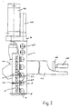
- the scrap shears shown in FIGS. 1 and 2 consist of a scissor stand 1, the columns 2, 3 of which are connected at the top by a crosshead 4 and at the bottom by a base plate 5 and a lower knife holder 6 to form a rigid frame.
- the base plate 5 is attached to a foundation 7.
- the columns 2, 3 of the scissor stand 1 are provided with slide strips 8, 9, in which an upper knife 10 carrying knife carriage 11 is arranged to be vertically displaceable.
- the inclined upper knife 10 is operatively connected to a lower knife 12 rigidly attached to the lower knife holder 6.
- a feed trough 13 for receiving the scrap is provided with a stamp 14 which can be moved slowly therein.
- the scrap moved by the punch 14 in preparation for the shearing process beyond the shear plane is grasped by a tamper 15 arranged in front of the shearing knives and guided vertically on the scissor stand 1, if necessary compacted and held down during the shearing process.
- a tamper 15 arranged in front of the shearing knives and guided vertically on the scissor stand 1, if necessary compacted and held down during the shearing process.
- of the tamper 15 and the plunger 14 is carried out by hydraulic drives in the form of cylinder-piston arrangements 16, 17 and 18.
- the slide bar 9 which is also the case for the non-visible slide bar 8 according to FIG. 1 applies to the column 3 of the scissor stand 1 by means of screw connections 21 consisting of screw 19 and nut 20.
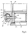
- Prestressed ring spring elements 22 are arranged between the corresponding inner surface of the column 3 and the nut 20.
- the ring spring element 22 consists of a pressure plate 23, a ring spring 24 and a pressure flange 25. Via the receiving screws 26 connecting the pressure plate 23 and the pressure flange 25, the required preload of the ring spring elements 22 is set and maintained at least until the screw connections 21 are made are.
- the threaded pressure flange 25 can also serve as the nut 20.
- the pressure plate 23 can, as shown, be welded to the corresponding inside of the respective column 2, 3.
- the prestressed ring spring element 22 is provided as an alternative to the arrangement according to FIGS. 2 and 3 between the screw head of the screw 19 and the slide bar 9.
- a prestressed ring spring element 22 can also be provided on each of the two sides. Furthermore, the position of screw 19 and nut 20 can be exchanged.
- the corresponding surfaces 27, 28 on the knife carriage 11 and on the slide strips 8, 9, which serve for the vertical guidance of the knife carriage 11, have an essentially constant and approximately matching radius of curvature.
- elastic deflection of the knife carriage 11 does not lead to an increased surface pressure of individual areas of the surfaces 27, 28 and thus does not lead to greater wear of the slide channels 29 provided in this embodiment variant.
- slide channels 29 wear and thus there is increased play between the knife slide 11 and the Slide strips 8, 9 can be readjusted for slide strips 8, 9 by loosening the screw connections 21, displacing one or both slide strips 8, 9 at elongated holes 30 in the direction of the knife carriage 11, replacing a compensating body 31 with a corresponding size and subsequently the screw connection 21 again will be produced.
- the mother-side end of the screw connection 21 is accessible through an opening 32 in the column 3 of the scissor stand 1.
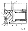
- an angle profile 33 is part of the column 3 of the scissor stand 1.
- a slide bar 34 has bolts 35 which are arranged horizontally. Engage slots 36 of the angle profile 33.
- an elastic layer 37 is provided which extends continuously and essentially over the entire length of the slide bar 34. If a liquid encapsulated by a solid is used as the elastic layer 37, the hydraulic pressure prevailing in the system is a measure of the preload achieved. If the pretension is exceeded, liquid is withdrawn from the system via a pressure relief valve, the liquid being able to be fed back in to restore the initial state.
- a trapezoidal guide is provided on the slide bar 34 for the knife carriage 11 having a corresponding recess.
- This type of guide for the knife carriage 11 is primarily used for scrap, which only offers relatively little resistance to shearing and thus only leads to negligible deformations of the knife carriage 11.
- the stress on the trapezoidal guide which varies during the shearing process is met in that the slideway 38 has a larger effective area than the slideway 39.
- the slide bar 34 is displaced in the direction of the knife carriage 11 and its end position is determined by a compensating body 40.
- the scrap fed into the feed trough 13 is moved from the punch 14 into the shear area and held down by the tamper 15.
- the scrap is separated between the upper knife 10 moved with the knife carriage 11 and the lower knife 12 which is rigidly arranged relative to the latter.
- the knife carriage tries to avoid the upper knife 10 for 11 minutes. This prevents him from reaching a certain preselectable prestress, which results from the total of the prestresses of the individual elastic elements 22, 37.
- the normal operation of the scissors is only interrupted after this pretension has been exceeded, in that the knife carriage 11 moves out of the shear plane and thus releases a larger shear gap. Jamming of the scrap therefore only occurs in the enlarged shear gap. Such jamming can in principle be remedied by the upward movement of the knife carriage 11.
- a sensor 41 is arranged in the area of the ring spring elements 22, which detects changes in the distance of the pressure flange 25 from one side of the column 3 of the scissor stand 1, which changes the distance on the opposite side of the column 3 of the scissor stand 1 of the slide strips 8, 9, 34 correspond. Furthermore, the sensor 41 is used to detect the remaining spring travel of the ring spring elements 22, so that the scissors can be switched off to avoid accidents when a minimal residual spring travel is reached.
Abstract
Description
Die Erfindung betrifft eine Schere zum Trennen von Schrott nach dem Oberbegriff des Anspruchs 1.The invention relates to scissors for separating scrap according to the preamble of claim 1.
Bei vorgenannten Scheren liegt das Problem vor, daß es insbesondere in Abhägigkeit von der Schrottqualität, der Schrottzusammensetzung und der Messergeometrie der Schermesser mehr oder weniger häufig zu einem Einziehen des Schrottes in den Scherspalt und zu einem Verklemmen des Messerschlittens kommt. Die hierbei auf den Messerschlitten, das Messerschlittenführungssystem und den Scherenständer wirkenden Kräfte können derart hoch sein, daß die maximal verfügbare Kraft des hydraulischen Messerantriebes nicht mehr ausreicht, um den Messerschlitten zurückzuziehen. In solchem Fall ist es notwendig, den verklemmten Schrott aus dem Scherspalt zu entfernen. Dies ist aber nur mit hohem Arbeitsaufwand möglichThe problem with the aforementioned scissors is that, depending in particular on the quality of the scrap, the composition of the scrap and the geometry of the knife, the scraps are more or less frequently drawn into the scissor gap and the knife carriage jams. The forces acting on the knife carriage, the knife carriage guide system and the scissor stand can be so high that the maximum available force of the hydraulic knife drive is no longer sufficient to pull the knife carriage back. In such a case, it is necessary to remove the jammed scrap from the shear gap. However, this is only possible with a lot of work
Weiterhin kann eine große Klemmkraft bleibende Verformungen am Messerschlitten, an dessen Führung und am Scherenständer hervorrufen Der Ausgleich der eingetretenen Verformungen ist äußerst kompliziert und führt zu einem längeren Stillstand der Schere.Furthermore, a large clamping force can cause permanent deformations on the knife carriage, on its guide and on the scissor stand. The compensation of the deformations that have occurred is extremely complicated and leads to the scissors being stationary for a long time.
Um diesem Problem zu begegnen, ist aus der DE-PS 39 29 183 eine Schrottschere bekannt, bei der die Führungen des Messerschlittens - im Gegensatz zu bekannten, formschlüssig am Scherenständer angeordneten Führungendurch Schraubverbindungen mit den Säulen des Scherenständers lösbar verbunden sind.In order to counter this problem, a scrap shear is known from DE-PS 39 29 183 in which the guides of the knife carriage - in contrast to known guides arranged in a form-fitting manner on the scissor stand - are detachably connected to the columns of the scissor stand by screw connections.
Wird bei dieser Lösung der Schrott in den Scherspalt eingezogen und dabei verklemmt, so kann er durch Lösen einer oder beider Führungen vergleichsweise leicht aus dem nunmehr verbreiterten Scherspalt entfernt werden.With this solution, if the scrap is drawn into the shear gap and jammed in the process, it can be removed comparatively easily from the now widened shear gap by loosening one or both guides.
Abgesehen von dem nicht unbedeutenden Aufwand zum Lösen der Schrauben der Führungen kann mit dieser Schere ein Verklemmen des Schrottes im Scherspalt nicht verhindert und eine bleibende Deformation Von Teilen der Schere, die die Funktionsfähigkeit der Schere möglicherweise einschränkt, nicht vermieden werden.Apart from the not insignificant effort to loosen the screws of the guides, jamming of the scrap in the shear gap cannot be prevented with these scissors and permanent deformation of parts of the scissors, which may restrict the functionality of the scissors, cannot be avoided.
Von daher liegt der Erfindung die Aufgabe zugrunde, eine Schere der eingangs genannten Art so auszubilden, daß in den Scherspalt eingezogener Schrott nicht zu Deformationen an der Schere und damit zu einer verminderten Funktionsfähigkeit derselben führt und daß der Schrott mit weiter Verringertem Aufwand aus dem Scherspalt entfernt werden kann.The invention is therefore based on the object of designing scissors of the type mentioned at the outset in such a way that scrap drawn into the shear gap does not lead to deformations of the scissors and thus to reduced functionality thereof, and that the scrap is removed from the shear gap with further reduced effort can be.
Diese Aufgabe wird bei einer gattungsgemäßen Schere durch die im kennzeichnenden Teil des Anspruchs 1 vermittelte Lehre gelöst.This object is achieved in a generic pair of scissors by the teaching conveyed in the characterizing part of claim 1.
Die mit der Erfindung erzielten Vorteile resultieren im wesentlichen daraus, daß der Messerschlitten bei Auftreten einer in Horizontalrichtung wirkenden Komponente der Scherkraft vorbestimmbarer Größe seine Bewegungsebene verläßt und entgegen der Wirkung elastischer Elemente unter Bildung eines verbreiterten Scherspaltes horizontal ausweicht. In Ausweichstellung des Messerschlittens ist die Klemmkraft wesentlich geringer als die Kraft des hydraulischen Messerantriebes, so daß der Messerschlitten trotz wirkender Klemmkraft zurückgezogen werden kann und der Schrott allein durch diesen Bewegungsablauf freigegeben wird.The advantages achieved with the invention essentially result from the fact that the knife carriage leaves its plane of movement when a component of the shear force of a predeterminable size acting in the horizontal direction occurs and deviates horizontally against the action of elastic elements to form a widened shear gap. In the alternative position of the knife carriage, the clamping force is considerably less than the force of the hydraulic knife drive, so that the knife carriage can be withdrawn despite the acting clamping force and the scrap is released solely by this sequence of movements.
Da die elastischen Elemente derart dimensioniert sind, daß auch bei horizontal aus seiner Bewegungsebene verschobenem Messerschlitten eine Elastizität dieser Elemente erhalten bleibt, können Deformationen an der Schere infolge von im Scherspalt verklemmtem Schrottes nicht auftraten. Werden als elastische Elemente Federelemente eingesetzt, so ist deren Restfederweg Ausdruck der verbleibenden ElastizitätSince the elastic elements are dimensioned such that an elasticity of these elements is retained even when the knife carriage is horizontally displaced from its plane of movement, deformations on the scissors as a result of scrap jammed in the shear gap cannot occur. If spring elements are used as elastic elements, their remaining spring travel is an expression of the remaining elasticity
Grundsätzlich gibt es für die Anordnung der elastischen Elemente zwei Möglichkeiten, die auch Kombinierbar sind. Zum einen kann der Messerschlitten gegenüber seinen Führungen horizontal elastisch angeordnet und die Führungen am Scherenständer starr befestigt sein. Andererseits können bei starr geführtem Messerschlitten die Führungen am Scherenständer horizontal elastisch befestigt sein, so daß die Bewegung einer oder beider Führungen eine gebundene Bewegung des Messerschlittens erzeugt. Die nachfolgenden Ausführungen zu letzterer Ausbildung der Erfindung sind entsprechend auf die erstgenannte anwendbar.There are basically two options for the arrangement of the elastic elements, which can also be combined. On the one hand, the knife carriage can be arranged horizontally elastically with respect to its guides and the guides can be rigidly attached to the scissor stand. On the other hand, with rigidly guided Knife carriage the guides on the scissor stand be horizontally elastically fastened so that the movement of one or both guides produces a bound movement of the knife carriage. The following statements on the latter embodiment of the invention are applicable accordingly to the former.
In Ausgestaltung der Erfindung ist vorgesehen, die durchschnittlichen Vorspannungen der Führungen des Messerschlittens voneinander verschieden zu wählen, wobei eine der Führungen auch starr am Scherenständer angeordnet sein kann. Hierdurch führt ein Ausweichen des Messerschlittens zu einem Scherspalt unterschiedlicher Breite.In an embodiment of the invention, it is provided that the average prestresses of the guides of the knife carriage are selected differently from one another, it being possible for one of the guides to also be arranged rigidly on the scissor stand. As a result, deflection of the knife carriage leads to a shear gap of different widths.
Bei Einsatz eines schräggestellten Messers wird zweckmäßig jene Führung mit einer geringeren Vorspannung versehen, auf deren Seite das Messer zuerst mit dem Schrott in Eingriff gelangt, um im Bedarfsfall eine Scherspalterweiterung ausreichender Größe zu erhalten.When using an inclined knife, the guide is expediently provided with a lower pretension, on the side of which the knife first comes into engagement with the scrap in order to obtain a shear gap widening of sufficient size if necessary.
Die elastischen Elemente sind bevorzugt als Einzelelemente im wesentlichen über den gesamten Verschiebeweg des Messerschlittens verteilt. Es ist jedoch auch möglich, einer jeden Führung nur ein, sich im wesentlichen über den gesamten Verschiebeweg des Messerschlittens erstreckendes, elastisches Element zuzuordnen.The elastic elements are preferably distributed as individual elements essentially over the entire displacement path of the knife carriage. However, it is also possible to assign only one elastic element to each guide, which element extends essentially over the entire displacement path of the knife carriage.
Die Erfindung soll nachfolgend anhand von Zeichnungen, die mögliche Ausführungsformen der Erfindung darstellen, näher erläutert werden.The invention will be explained in more detail below with the aid of drawings which illustrate possible embodiments of the invention.
Es zeigen:
- Fig. 1
- eine Frontansicht einer Schrottschere,
- Fig. 2
- eine Seitenangicht der Schrottschere gem. Fig. 1,
- Fig. 3
- ein Ringfederelement in vergrößerter Darstellung,
- Fig. 4
- einen Horizontalschnitt einer Seite des Scherenständers in Höhe eines möglichen Elementes zur Verbindung der Messerschlittenführung mit dem Scherenständer,
- Fig. 5
- einen Schnitt gemäß Fig. 4 mit einem weiteren möglichen Verbindungselement.
- Fig. 1
- a front view of a scrap shear,
- Fig. 2
- a side view of the scrap shear acc. Fig. 1
- Fig. 3
- an annular spring element in an enlarged view,
- Fig. 4
- a horizontal section of one side of the scissor stand at the level of a possible element for connecting the knife carriage guide to the scissor stand,
- Fig. 5
- a section of FIG. 4 with another possible connecting element.
Die in den Fig. 1 und 2 dargestellte Schrottschere besteht aus einem Scherenständer 1, dessen Säulen 2, 3 oben durch ein Querhaupt 4 und unten durch eine Grundplatte 5 sowie eine Untermesserhalterung 6 zu einem starren Rahmen verbunden sind. Die Grundplatte 5 ist auf einem Fundament 7 befestigt. Die Säulen 2, 3 des Scherenständers 1 sind mit Gleitleisten 8,9 versehen, in denen ein Obermesser 10 tragender Messerschlitten 11 vertikal verschiebbar angeordnet ist. Das schräggestellte Obermesser 10 steht beim Schervorgang in Wirkverbindung mit einem an der Untermesserhalterung 6 starr angebrachten Untermesser 12. Eine der Aufnahme des Schrottes dienende Zuführmulde 13 ist mit einem in dieser langsverschiebbaren Stempel 14 versehen. Der vom Stempel 14 in Vorbereitung des Schervorganges über die Scherebene hinaus bewegte Schrott wird von einem, vor den Schermessern angeordneten und vertikal am Scherenständer 1 geführten, Stampfer 15 erfaßt, ggf. verdichtet und beim Schervorgang niedergehalten Die Betätigung des das Obermesser 10 tragenden Messerschlittens 11, des Stampfers 15 und des Stempels 14 erfolgt durch hydraulische Antriebe in Form von Zylinder-Kolben-Anordnungen 16, 17 und 18.The scrap shears shown in FIGS. 1 and 2 consist of a scissor stand 1, the
Wie aus Fig. 2 ersichtlich, ist die Gleitleiste 9, was entsprechend auch für die nicht sichtbare Gleitleiste 8 gem. Fig. 1 gilt, durch aus Schraube 19 und Mutter 20 bestehende Schraubverbindungen 21 mit der Säule 3 des Scherenständers 1 verbunden Zwischen der entsprechenden Innenfläche der Säule 3 und der Mutter 20 sind vorgespannte Ringfederelemente 22 angeordnet.As can be seen from FIG. 2, the slide bar 9, which is also the case for the non-visible slide bar 8 according to FIG. 1 applies to the
Gemäß Fig. 3 besteht das Ringfederelement 22 aus einer Druckplatte 23, einer Ringfeder 24 und einem Druckflansch 25. Über die die Druckplatte 23 und den Druckflansch 25 verbindenden Aufnahmeschrauben 26 wird die erforderliche Vorspannung der Ringfederelemente 22 eingestellt und zumindest solange aufrechterhalten bis die Schraubverbindungen 21 hergestellt sind. Als Mutter 20 kann dabei auch der mit Gewinde versehene Druckflansch 25 dienen. Im eingebauten Zustand kann die Druckplatte 23, wie dargestellt, mit der entsprechenden Innenseite der jeweiligen Säule 2, 3 verschweißt sein.3, the
In der Ausführungsvariante nach Fig. 4 ist das vorgespannte Ringfederelement 22 alternativ zu der Anordnung gemäß Fig. 2 und 3 zwischen dem Schraubenkopf der Schraube 19 und der Gleitleiste 9 vorgesehen. Auch kann auf jeder der beiden Seiten ein vorgespanntes Ringfederelement 22 vorgesehen sein. Weiterhin kann ein Positionstausch von Schraube 19 und Mutter 20 erfolgen.4, the prestressed
Die der Vertikalführung des Messerschlittens 11 dienenden, korrespondierenden Flächen 27, 28 am Messerschlitten 11 und an den Gleitleisten 8, 9 weisen einen im wesentlichen konstanten und annähernd übereinstimmenden Krümmungsradius auf. Hierdurch führt ein elastisches Ausweichen des Messerschlittens 11 nicht zu einer erhöhten Flächenpressung einzelner Bereiche der Flächen 27, 28 und damit nicht zu einem höheren Verschleiß der bei dieser Ausführungsvariante vorgesehenen Gleitrinnen 29. Bei Abnutzung der Gleitrinnen 29 und damit vergrößertem Spiel zwischen dem Messerschlitten 11 und den Gleitleisten 8, 9 kann eine Nachstellung der Gleitleisten 8, 9 erfolgen, indem die Schraubverbindungen 21 gelöst, eine oder beide Gleitleisten 8, 9 an Langlöchern 30 in Richtung Messerschlitten 11 verschoben, ein Ausgleichskörper 31 durch einen entsprechender Größe ersetzt und nachfolgend die Schraubverbindung 21 wieder hergestellt wird.The corresponding surfaces 27, 28 on the
Um diese Arbeiten, wie auch das erstmalige Herstellen der Schraubverbindungen 21, zu erleichtern, ist das mutterseitige Ende der Schraubverbindung 21 durch eine Öffnung 32 in der Säule 3 des Scherenständers 1 zugänglich.In order to facilitate this work, as well as making the
Gemäß der Ausführung nach Fig. 5 ist ein Winkelprofil 33 Bestandteil der Säule 3 des Scherenständers 1. Eine Gleitleiste 34 weist Bolzen 35 auf, die in horizontal angeordnete. Langlöcher 36 des Winkelprofils 33 eingreifen. Zwischen dem freien Ende des Winkelprofils 33 und der Gleitleiste 34 ist eine elastische Schicht 37 vorgesehen, die sich kontinuierlich und im wesentlichen über die gesamte Länge der Gleitleiste 34 erstreckt. Kommt als elastische Schicht 37 eine durch einen Festkörper gekapselte Flüssigkeit zum Einsatz, so ist der im System vorherrschende Hydraulikdruck ein Maß für die erreichte Vorspannung. Bei Überschreiten der Vorspannung wird über ein Druckbegrenzungsventil Flüssigkeit dem System entzogen, wobei die Flüssigkeit zur Herstellung des Ausgangszustandes wieder eingespeist werden kann.5, an
An der Gleitleiste 34 ist eine Trapezführung für den eine entsprechende Aussparung aufweisenden Messerschlitten 11 vorgesehen Diese Art der Führung des Messerschlittens 11 wird vorrangig für Schrott, der dem Abscheren nur einen relativ geringen Widerstand entgegensetzt und damit nur zu vernachlässigbaren Verformungen des Messerschlittens 11 führt, eingesetzt. Der beim Schervorgang unterschiedlich starken Beanspruchung der Trapezführung ist entsprochen, indem die Gleitbahn 38 eine größere wirksame Fläche als die Gleitbahn 39 aufweist. Zum Ausgleich übermäßigen Spiels an der Trapezführung wird die Gleitleiste 34 in Richtung Messerschlitten 11 verschoben und deren Endlage durch einen Ausgleichskörper 40 festgelegt.A trapezoidal guide is provided on the
In Vorbereitung des Schervorganges wird der in die Zuführmulde 13 aufgegebene Schrott vom Stempel 14 in den Scherbereich verschoben und durch den Stampfer 15 niedergehalten. Infolge der Vertikalbewegung des Messerschlittens 11 kommt es zu einem Trennen des Schrottes zwischen dem mit dem Messerschlitten 11 bewegten Obermesser 10 und dem gegenüber diesem starr angeordneten Untermesser 12.In preparation for the shearing process, the scrap fed into the
Enthält der Schrott Bestandteile mit geringem Widerstandsmoment, die vom Obermesser 10 in den Scherspalt gebogen werden und/oder zeigt das Obermesser 10 Verschleißerscheinungen vorrangig an der Schneidkante, so versucht der Messerschlitten 11 min dem Obermesser 10 auszuweichen. Daran ist er bis zum Erreichen einer bestimmten, vorwählbaren Vorspannung, die sich aus der Gesamtheit der Vorspannungen der einzelnen elastischen Elemente 22, 37 ergibt, gehindert. Erst nach Überschreiten dieser Vorspannung wird der Normalbetrieb der Schere unterbrochen, indem sich der Messerschlitten 11 aus der Scherebene herausbewegt und damit einen größeren Scherspalt freigibt. Ein Verklemmen des Schrottes tritt daher nur im vergrößerten Scherspalt auf. Ein solches Verklemmen wird grundsätzlich durch die Aufwärtsbewegung des Messerschlittens 11 behoben werden können. Sollte in Ausnahmefällen die Klemmkraft so groß sein, daß der Messeerschlitten 11 nicht mehr verschoben werden kann, ist seine Verschiebbarkeit wiederherstellbar, indem bspw. die Vorspannung der Ringfederelemente 22 durch die Aufnahmeschrauben 26 erhöht wird.
Aus der Häufigkeit
und der Art des Ausweichens des Messerschlittens 11 kann auf den Verschleißgrad von Obermesser 10 und Untermesser 12 geschlossen werden. Hierzu ist, bspw. wie in Fig. 3 dargestellt, ein Sensor 41 im Bereich der Ringfederelemente 22 angeordnet, der Abstandsänderungen des Druckflansches 25 von der einen Seite der Säule 3 des Scherenständers 1 erfaßt, die den Abstandsänderungen der gegenüberliegenden Seite der Säule 3 des Scherenständers 1 von den Gleitleisten 8, 9, 34 entsprechen. Weiterhin dient der Sensor 41 dem Erkennen des noch verfügbaren Restfederweges der Ringfederelemente 22 , so daß zur Vermeidung von Störfällen bei Erreichen eines minimalen Restfederweges die Schere abgeschaltet werden kann.If the scrap contains components with a low section modulus that are bent into the shear gap by the
From the frequency
and the nature of the divergence of the
Claims (12)
- Shears for severing scrap metal, with a shears stand (1) on which a cutter slide (11) is capable of being displaced vertically in guide channels (8, 9, 34) arranged on the shears stand (1), a first cutter (10) borne by the cutter slide (11) and a second cutter (12) interacting with said first cutter and firmly arranged on the shears stand (1), characterised in that the cutter slide (11) is capable of being moved in opposition to the action of elastic elements (22, 37) substantially perpendicular to the plane of the shears subject to formation of a wider shear gap.
- Shears according to Claim 1, characterised in that the guide channels (8, 9) of the cutter slide (11) are capable of being moved in opposition to the action of elastic elements (22, 37) substantially perpendicular to the plane of the shears.
- Shears according to Claim 2, characterised in that the elastic elements (22, 37) are prestressed.
- Shears according to Claim 3, characterised in that the average prestressing of the elastic elements (22, 37) to be assigned to the one guide channel (8, 9) differs from the average prestressing of the elastic elements (22, 37) to be assigned to the other guide channel (9, 8).
- Shears according to Claim 4, characterised in that one of the guide channels (8, 9) is rigidly connected to the shears stand (1) and the other guide channel (9, 8) is connected to the shears stand (1) via a prestressed elastic element (22, 37).
- Shears according to one of Claims 1 to 5, characterised in that the elastic elements (22) are distributed as individual elements over substantially the entire displacement path of the cutter slide (11).
- Shears according to one of Claims 1 to 5, characterised in that an elastic element (37) extends on either side of the cutter slide (11) over substantially the entire displacement path of the cutter slide (11).
- Shears according to Claim 6, characterised in that the elastic elements are designed as annular spring elements.
- Shears according to Claim 8, characterised in that the annular spring element (22) consists of a pressure plate (23), a pressure flange (25) and an intermediate annular spring (24), whereby the prestressing is produced by take-up screws (26) connecting the pressure plate (23) and the pressure flange (25).
- Shears according to Claim 8 or 9, characterised in that the guide channels (8, 9) and the elastic elements (22) are secured to the shears stand (1) by screw connections (21).
- Shears according to one of the aforementioned claims, characterised in that, viewed at right angles to the plane of the shears, the guide channels (34) and the elastic elements (37) are inserted into the shears stand (1) in interlocking manner.
- Shears according to one of the aforementioned claims, characterised in that the corresponding surfaces (27, 28) of the cutter slide (11) and of the guide channels (8, 9) serving to guide the cutter slide (11) vertically exhibit a substantially constant and approximately coincident radius of curvature.
Applications Claiming Priority (2)
| Application Number | Priority Date | Filing Date | Title |
|---|---|---|---|
| DE4204841A DE4204841C1 (en) | 1992-02-18 | 1992-02-18 | |
| DE4204841 | 1992-02-18 |
Publications (2)
| Publication Number | Publication Date |
|---|---|
| EP0557866A1 EP0557866A1 (en) | 1993-09-01 |
| EP0557866B1 true EP0557866B1 (en) | 1995-07-19 |
Family
ID=6451970
Family Applications (1)
| Application Number | Title | Priority Date | Filing Date |
|---|---|---|---|
| EP93102406A Expired - Lifetime EP0557866B1 (en) | 1992-02-18 | 1993-02-16 | Scrap shear |
Country Status (9)
| Country | Link |
|---|---|
| US (1) | US5647262A (en) |
| EP (1) | EP0557866B1 (en) |
| JP (1) | JPH05337725A (en) |
| CN (1) | CN1085478A (en) |
| AT (1) | ATE125180T1 (en) |
| CZ (1) | CZ18393A3 (en) |
| DE (2) | DE4204841C1 (en) |
| ES (1) | ES2075728T3 (en) |
| SK (1) | SK9393A3 (en) |
Families Citing this family (11)
| Publication number | Priority date | Publication date | Assignee | Title |
|---|---|---|---|---|
| CZ296867B6 (en) * | 2001-06-20 | 2006-07-12 | Zdas, A. S. | Scrap cutting shears |
| DE10212730A1 (en) * | 2002-03-21 | 2004-02-12 | Metso Lindemann Gmbh | Press for processing any kind of material |
| DE10243125A1 (en) * | 2002-09-18 | 2004-04-01 | Atlas Copco Construction Tools Gmbh | Device on scrap shears or the like - to reduce the frictional forces that occur under the influence of the crushing material in the course of the closing movement |
| ES2219194B1 (en) * | 2004-03-15 | 2006-06-01 | Gamei, S.A. | SHEAR FOR IMPROVED METAL BARS. |
| JP2008068340A (en) * | 2006-09-12 | 2008-03-27 | Nippon Primex Inc | Sheet cutter |
| CN101695771B (en) * | 2009-11-05 | 2013-06-05 | 四川长虹电器股份有限公司 | Copper and aluminum separating equipment of waste air conditioner heat exchanger |
| DE102010024403A1 (en) * | 2010-06-19 | 2011-12-22 | Sms Siemag Aktiengesellschaft | Method and device for scrap knife gap adjustment in heavy plate shears |
| CN108480759A (en) * | 2018-03-28 | 2018-09-04 | 太原科技大学 | A kind of automatic shearing production method of blast furnace steel-making temperature adjustment metal derby |
| JP7237336B2 (en) * | 2018-11-08 | 2023-03-13 | 株式会社エムダイヤ | Cutting machine |
| CN109746687A (en) * | 2019-02-27 | 2019-05-14 | 厦门精友诚机械有限公司 | A kind of strip shearing bonding machine |
| CN109926633A (en) * | 2019-03-14 | 2019-06-25 | 富华中元江苏重机科技有限公司 | A kind of fashioned iron cold shears cutting mechanism |
Family Cites Families (11)
| Publication number | Priority date | Publication date | Assignee | Title |
|---|---|---|---|---|
| DE845438C (en) * | 1951-04-13 | 1952-11-04 | Waldemar Lindemann | Scrap shears, especially for bulky and / or voluminous material to be cut |
| DE1915600C2 (en) * | 1969-03-27 | 1984-04-26 | Enka Ag, 5600 Wuppertal | Cutting device for machines with reciprocating knife movement for cutting fiber cables, foils and the like. |
| US4220063A (en) * | 1978-08-24 | 1980-09-02 | The Steelastic Company | Guillotine assembly |
| JPS571363A (en) * | 1980-06-03 | 1982-01-06 | Toyoko Miyazaki | Training machine for golf swing |
| DE3541640A1 (en) * | 1985-11-26 | 1987-05-27 | Bielomatik Leuze & Co | Cutting device for paper or the like |
| CH671726A5 (en) * | 1987-01-30 | 1989-09-29 | Charmilles Technologies | |
| JPS6487110A (en) * | 1987-09-29 | 1989-03-31 | Aizawa Tekkosho Kk | Blade part gap regulating device for shearing machine |
| IT1214004B (en) * | 1987-10-13 | 1990-01-05 | Eugenio Lenzotti | PUNCHING AND SHEARING MACHINE WITH VARIABLE CUTTING ANGLE |
| JP2665234B2 (en) * | 1988-06-23 | 1997-10-22 | 株式会社アマダ | Shearing machine |
| DE3929183A1 (en) * | 1989-09-02 | 1991-03-14 | Thyssen Industrie | Press for cutting up scrap metal - has moving blade mounted on slide with adjustable guide rails |
| DE3940717A1 (en) * | 1989-12-09 | 1991-06-13 | Thyssen Industrie | KNIFE HOLDER ON THE KNIFE SLIDE OF A SCRAP SHEAR |
-
1992
- 1992-02-18 DE DE4204841A patent/DE4204841C1/de not_active Expired - Fee Related
-
1993
- 1993-02-09 JP JP5021427A patent/JPH05337725A/en active Pending
- 1993-02-12 CZ CZ93183A patent/CZ18393A3/en unknown
- 1993-02-15 SK SK9393A patent/SK9393A3/en unknown
- 1993-02-16 AT AT93102406T patent/ATE125180T1/en active
- 1993-02-16 ES ES93102406T patent/ES2075728T3/en not_active Expired - Lifetime
- 1993-02-16 EP EP93102406A patent/EP0557866B1/en not_active Expired - Lifetime
- 1993-02-16 DE DE59300358T patent/DE59300358D1/en not_active Expired - Fee Related
- 1993-02-18 CN CN93102696A patent/CN1085478A/en active Pending
-
1995
- 1995-02-28 US US08/396,338 patent/US5647262A/en not_active Expired - Fee Related
Also Published As
| Publication number | Publication date |
|---|---|
| ES2075728T3 (en) | 1995-10-01 |
| US5647262A (en) | 1997-07-15 |
| ATE125180T1 (en) | 1995-08-15 |
| EP0557866A1 (en) | 1993-09-01 |
| DE59300358D1 (en) | 1995-08-24 |
| DE4204841C1 (en) | 1993-09-09 |
| SK9393A3 (en) | 1993-09-09 |
| CN1085478A (en) | 1994-04-20 |
| CZ18393A3 (en) | 1994-04-13 |
| JPH05337725A (en) | 1993-12-21 |
Similar Documents
| Publication | Publication Date | Title |
|---|---|---|
| DE60215809T2 (en) | LENGTH ADJUSTABLE PUNCH TOOL | |
| EP0453933B1 (en) | Device for cutting of stacked sheet products | |
| DE2142570C3 (en) | Mechanical powder press, in particular metal powder press | |
| DE3106353C2 (en) | ||
| DE2855164C2 (en) | Cover strip arrangement for belt conveyor | |
| EP0557866B1 (en) | Scrap shear | |
| DE2359313A1 (en) | CONCRETE CRUSHER | |
| DE2507450A1 (en) | MACHINE SHEARS WITH IMPROVED KNIFE HOLDER | |
| DE2810595C2 (en) | Adjustment device for adjusting the closing height of a press | |
| EP1781440B1 (en) | Guillotine shears for sheet metal | |
| DE3826426C2 (en) | Shearing machine for plate-shaped workpieces | |
| DE19928841C1 (en) | Sheet metal cutting device | |
| DE2838733C2 (en) | Section steel shears and / or punches | |
| EP0838277B1 (en) | Leveller for levelling strips to be fed to the entrance of a press | |
| EP0389897B1 (en) | Equipment for welding of bands | |
| DE2332898A1 (en) | FLAT KNIFE SHEARS FOR TRIMMING ROLLED PLATE | |
| DE2654000A1 (en) | MACHINE TO BREAK OUT BENEFITS | |
| DE102018206775B4 (en) | Punch for cutting a film web, especially for a packaging machine | |
| DE2652886A1 (en) | Sheet material folding tool - has lower part of auxiliary punch movable relative to main punch and guided by pin engaging in slots | |
| DE3832853C2 (en) | ||
| DE3929183C2 (en) | ||
| DE102004006799B4 (en) | Cutting device for web materials | |
| EP0733427B1 (en) | Apparatus for cutting scrap | |
| DE3428863A1 (en) | Glass breaking machine | |
| DE2654751B2 (en) | Scrap shears |
Legal Events
| Date | Code | Title | Description |
|---|---|---|---|
| PUAI | Public reference made under article 153(3) epc to a published international application that has entered the european phase |
Free format text: ORIGINAL CODE: 0009012 |
|
| AK | Designated contracting states |
Kind code of ref document: A1 Designated state(s): AT BE CH DE DK ES FR GB GR IT LI LU NL PT SE |
|
| 17P | Request for examination filed |
Effective date: 19931018 |
|
| 17Q | First examination report despatched |
Effective date: 19941229 |
|
| GRAA | (expected) grant |
Free format text: ORIGINAL CODE: 0009210 |
|
| AK | Designated contracting states |
Kind code of ref document: B1 Designated state(s): AT BE CH DE DK ES FR GB GR IT LI LU NL PT SE |
|
| PG25 | Lapsed in a contracting state [announced via postgrant information from national office to epo] |
Ref country code: IT Free format text: LAPSE BECAUSE OF FAILURE TO SUBMIT A TRANSLATION OF THE DESCRIPTION OR TO PAY THE FEE WITHIN THE PRESCRIBED TIME-LIMIT;WARNING: LAPSES OF ITALIAN PATENTS WITH EFFECTIVE DATE BEFORE 2007 MAY HAVE OCCURRED AT ANY TIME BEFORE 2007. THE CORRECT EFFECTIVE DATE MAY BE DIFFERENT FROM THE ONE RECORDED. Effective date: 19950719 Ref country code: GR Free format text: LAPSE BECAUSE OF FAILURE TO SUBMIT A TRANSLATION OF THE DESCRIPTION OR TO PAY THE FEE WITHIN THE PRESCRIBED TIME-LIMIT Effective date: 19950719 Ref country code: GB Effective date: 19950719 Ref country code: DK Effective date: 19950719 Ref country code: BE Effective date: 19950719 |
|
| REF | Corresponds to: |
Ref document number: 125180 Country of ref document: AT Date of ref document: 19950815 Kind code of ref document: T |
|
| ET | Fr: translation filed | ||
| REF | Corresponds to: |
Ref document number: 59300358 Country of ref document: DE Date of ref document: 19950824 |
|
| REG | Reference to a national code |
Ref country code: ES Ref legal event code: FG2A Ref document number: 2075728 Country of ref document: ES Kind code of ref document: T3 |
|
| PG25 | Lapsed in a contracting state [announced via postgrant information from national office to epo] |
Ref country code: SE Effective date: 19951019 Ref country code: PT Effective date: 19951019 |
|
| GBV | Gb: ep patent (uk) treated as always having been void in accordance with gb section 77(7)/1977 [no translation filed] |
Effective date: 19950719 |
|
| PG25 | Lapsed in a contracting state [announced via postgrant information from national office to epo] |
Ref country code: LI Free format text: LAPSE BECAUSE OF NON-PAYMENT OF DUE FEES Effective date: 19960228 Ref country code: CH Free format text: LAPSE BECAUSE OF NON-PAYMENT OF DUE FEES Effective date: 19960228 |
|
| PG25 | Lapsed in a contracting state [announced via postgrant information from national office to epo] |
Ref country code: LU Free format text: LAPSE BECAUSE OF NON-PAYMENT OF DUE FEES Effective date: 19960229 |
|
| PLBE | No opposition filed within time limit |
Free format text: ORIGINAL CODE: 0009261 |
|
| STAA | Information on the status of an ep patent application or granted ep patent |
Free format text: STATUS: NO OPPOSITION FILED WITHIN TIME LIMIT |
|
| 26N | No opposition filed | ||
| REG | Reference to a national code |
Ref country code: CH Ref legal event code: PL |
|
| PGFP | Annual fee paid to national office [announced via postgrant information from national office to epo] |
Ref country code: FR Payment date: 19970114 Year of fee payment: 5 |
|
| PGFP | Annual fee paid to national office [announced via postgrant information from national office to epo] |
Ref country code: DE Payment date: 19970124 Year of fee payment: 6 |
|
| PGFP | Annual fee paid to national office [announced via postgrant information from national office to epo] |
Ref country code: AT Payment date: 19970128 Year of fee payment: 5 |
|
| PGFP | Annual fee paid to national office [announced via postgrant information from national office to epo] |
Ref country code: NL Payment date: 19970130 Year of fee payment: 5 |
|
| PGFP | Annual fee paid to national office [announced via postgrant information from national office to epo] |
Ref country code: ES Payment date: 19970218 Year of fee payment: 5 |
|
| PG25 | Lapsed in a contracting state [announced via postgrant information from national office to epo] |
Ref country code: AT Free format text: LAPSE BECAUSE OF NON-PAYMENT OF DUE FEES Effective date: 19980216 |
|
| PG25 | Lapsed in a contracting state [announced via postgrant information from national office to epo] |
Ref country code: ES Free format text: LAPSE BECAUSE OF EXPIRATION OF PROTECTION Effective date: 19980217 |
|
| PG25 | Lapsed in a contracting state [announced via postgrant information from national office to epo] |
Ref country code: FR Free format text: THE PATENT HAS BEEN ANNULLED BY A DECISION OF A NATIONAL AUTHORITY Effective date: 19980228 |
|
| PG25 | Lapsed in a contracting state [announced via postgrant information from national office to epo] |
Ref country code: NL Free format text: LAPSE BECAUSE OF NON-PAYMENT OF DUE FEES Effective date: 19980901 |
|
| NLV4 | Nl: lapsed or anulled due to non-payment of the annual fee |
Effective date: 19980901 |
|
| REG | Reference to a national code |
Ref country code: FR Ref legal event code: ST |
|
| PG25 | Lapsed in a contracting state [announced via postgrant information from national office to epo] |
Ref country code: DE Free format text: LAPSE BECAUSE OF NON-PAYMENT OF DUE FEES Effective date: 19991201 |
|
| REG | Reference to a national code |
Ref country code: ES Ref legal event code: FD2A Effective date: 20000301 |