EP3291863B1 - Einweginjektor mit erhöhter auslösesicherheit - Google Patents
Einweginjektor mit erhöhter auslösesicherheit Download PDFInfo
- Publication number
- EP3291863B1 EP3291863B1 EP15720087.4A EP15720087A EP3291863B1 EP 3291863 B1 EP3291863 B1 EP 3291863B1 EP 15720087 A EP15720087 A EP 15720087A EP 3291863 B1 EP3291863 B1 EP 3291863B1
- Authority
- EP
- European Patent Office
- Prior art keywords
- housing
- triggering
- disposable injector
- use injector
- piston
- Prior art date
- Legal status (The legal status is an assumption and is not a legal conclusion. Google has not performed a legal analysis and makes no representation as to the accuracy of the status listed.)
- Not-in-force
Links
Images


Classifications
-
- A—HUMAN NECESSITIES
- A61—MEDICAL OR VETERINARY SCIENCE; HYGIENE
- A61M—DEVICES FOR INTRODUCING MEDIA INTO, OR ONTO, THE BODY; DEVICES FOR TRANSDUCING BODY MEDIA OR FOR TAKING MEDIA FROM THE BODY; DEVICES FOR PRODUCING OR ENDING SLEEP OR STUPOR
- A61M5/00—Devices for bringing media into the body in a subcutaneous, intra-vascular or intramuscular way; Accessories therefor, e.g. filling or cleaning devices, arm-rests
- A61M5/178—Syringes
- A61M5/20—Automatic syringes, e.g. with automatically actuated piston rod, with automatic needle injection, filling automatically
- A61M5/2033—Spring-loaded one-shot injectors with or without automatic needle insertion
-
- A—HUMAN NECESSITIES
- A61—MEDICAL OR VETERINARY SCIENCE; HYGIENE
- A61M—DEVICES FOR INTRODUCING MEDIA INTO, OR ONTO, THE BODY; DEVICES FOR TRANSDUCING BODY MEDIA OR FOR TAKING MEDIA FROM THE BODY; DEVICES FOR PRODUCING OR ENDING SLEEP OR STUPOR
- A61M5/00—Devices for bringing media into the body in a subcutaneous, intra-vascular or intramuscular way; Accessories therefor, e.g. filling or cleaning devices, arm-rests
- A61M5/178—Syringes
- A61M5/31—Details
- A61M5/315—Pistons; Piston-rods; Guiding, blocking or restricting the movement of the rod or piston; Appliances on the rod for facilitating dosing ; Dosing mechanisms
- A61M5/31565—Administration mechanisms, i.e. constructional features, modes of administering a dose
- A61M5/31576—Constructional features or modes of drive mechanisms for piston rods
- A61M5/31578—Constructional features or modes of drive mechanisms for piston rods based on axial translation, i.e. components directly operatively associated and axially moved with plunger rod
- A61M5/3158—Constructional features or modes of drive mechanisms for piston rods based on axial translation, i.e. components directly operatively associated and axially moved with plunger rod performed by axially moving actuator operated by user, e.g. an injection button
-
- A—HUMAN NECESSITIES
- A61—MEDICAL OR VETERINARY SCIENCE; HYGIENE
- A61M—DEVICES FOR INTRODUCING MEDIA INTO, OR ONTO, THE BODY; DEVICES FOR TRANSDUCING BODY MEDIA OR FOR TAKING MEDIA FROM THE BODY; DEVICES FOR PRODUCING OR ENDING SLEEP OR STUPOR
- A61M5/00—Devices for bringing media into the body in a subcutaneous, intra-vascular or intramuscular way; Accessories therefor, e.g. filling or cleaning devices, arm-rests
- A61M5/178—Syringes
- A61M5/20—Automatic syringes, e.g. with automatically actuated piston rod, with automatic needle injection, filling automatically
- A61M2005/2073—Automatic syringes, e.g. with automatically actuated piston rod, with automatic needle injection, filling automatically preventing premature release, e.g. by making use of a safety lock
Definitions
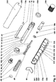
- FIGS. 1 to 14 show a disposable or disposable injector (4).
- injectors (4) are used for the single introduction of an injection solution (1) or a solvent stored in a cylinder-piston unit (100) into the skin of a patient.
- the disposable injector (4) comprises a jacket housing (82) in which an inner housing (10) with a piston actuating punch (60) and a helical compression spring (50) as permanently loaded spring energy storage (50) and a cylinder-piston unit (100) are arranged ,
- the cylinder-piston unit (100) is closed by means of a protective cap (120).
- the triggering of the disposable injector (4) is prevented by means of a safety slide (87). This can be removable for unlocking or it can be displaced in the disposable injector (4).
- the housing (10) and the jacket housing (82) are made for example of plastic. This may be a thermoset or thermoset material, eg POM, ABS, etc.
- the jacket housing (82) consists in the embodiment of an upper shell (220) and a lower shell (230).
- the two shells (220, 230) are connected to each other by means of pin connections (228, 238) and, for example, positively and / or materially secured.
- the upper shell (220) and the lower shell (230) may be glued together, welded, etc., for example.
- the upper shell (220) and the lower shell (230) can also be locked together.
- the cross-sectionally polygonal shell casing (82) has an at least approximately regular, triangular-like cross-section in the exemplary embodiment, cf. FIG. 5 ,
- the cross-sectional area in the rear region of the disposable injector (4) facing away from the injection site is 70% of the cross-sectional area in the front region of the disposable injector (4) facing the injection site.
- the steady increase in cross-sectional area, as seen by the operator, is in the third quarter of the length of the disposable injector (4).
- the disposable injector (4) comprises a tubular housing (10), in which a spring energy store (50) and a piston actuation plunger (60) are arranged.
- a spring energy store (50) and a piston actuation plunger (60) are arranged in the front.
- the injection point facing the housing (10) has inwardly projecting spring hook (42).
- the spring hook (42) is in the representations of FIGS. 3 and 4 the example pre-filled cylinder-piston unit (100) is inserted and locked.
- the housing (10) has a substantially cylindrical inner contour. In the rear, the injection point remote area an internal thread (11) is arranged. In this sits a support screw (12) with a hexagonal section (13).
- the outer contour of the housing (10) has a cylindrical basic shape with a flattening (14), cf. FIG. 2 , In the region of the flattening (14) is a support rod (21) on the housing (10).
- the support rod (21) protrudes with a clamping leg (25) in an upper slot (16) of the housing (10).
- a Umgriffshaken (26) of the support rod (21) protrudes through a lower opening (18) with a rectangular cross-sectional area (18) in the housing (10).
- the housing (10) in the longitudinal direction (5) of the disposable injector (4) oriented guide rib (15), see. the Figures 5 and 8th ,
- the piston actuating ram (60) comprises, for example, a cylindrical guide pin (62), a punch plate (73) and a piston slide (76).
- the guide pin (62) carries and guides the spring energy store (50), which is designed here as a helical compression spring (50). That in the FIGS. 3 and 4 Upper end of the helical compression spring (50) is supported via a disc (38) and the clamping leg (25) of the support rod (21) on the support screw (12).
- the guide pin (62) has circular-segment-shaped recesses (66) oriented in the radial direction.
- the disposable injector (4) can also be designed without the support disk (38).
- the punch plate (73) of the piston actuating punch (60) is disc-shaped and aligned normal to the central longitudinal axis (7) of the disposable injector (4). He has one of the helical compression spring (50) facing away, conically shaped collar surface (75). The apex angle of the imaginary cone of the collar surface (75) is e.g. 160 degrees.
- the support disc (160) is a perforated disc and has around the central bore around arranged grooves (163) and wedges (162), with which it sits positively on the piston slide (76) of the piston actuating punch (60).
- the support disk (160) is frusto-conical in the side view. It is for example made of a metallic material, for example an austenitic, corrosion-resistant steel. In the presentation of the FIG. 3 it is secured by means of the Umgriffshakens (26) of the support rod (21) in position.
- the rod-like piston slide (76) has an at least approximately cylindrical shape in the embodiment. For example, it has in the longitudinal direction of the disposable injector (4) aligned key surfaces (77). Along these key surfaces (77), air can escape more quickly when the piston slide (76) is dipped into the cylinder-piston unit (100).
- the support rod (21), cf. the Figures 2 . 3 and 12 is made of a metal strip with eg constant rectangular cross-sectional area.
- the width of the support rod (21) normal to the longitudinal direction (5) of the disposable injector (4) is eight in the embodiment Sometimes as big as its thickness.
- the material of the support rod (21) is an austenitic spring steel. For example, its modulus of elasticity is greater than 190,000 Newton per square millimeter.
- the support rod (21) comprises a main leg (27), the clamping leg (25) and the Umgriffshaken (26). In the presentation of the FIG. 3 the main leg (27) is parallel to the flat (14). Its length is for example seven times the width of the support rod (21).
- the front, in the FIG. 3 Lower end of the support rod (21) also points in the direction of the interior (17) and forms the Umgriffshaken (26).
- the Umgriffshaken (26) closes with the main leg (27) at an angle which is greater than the right angle by the inclination angle of the collar surface (75) to a normal plane of the central longitudinal axis (7) of the disposable injector (4).
- the cylinder-piston unit (100) comprises an eg transparent cylinder (101) and a piston (111) guided in the cylinder (101).
- the piston (111) sits in a rear position.
- a gap (141) Between the piston (111) and, also in the cylinder (101) guided piston slide (76) is a gap (141). Its length is in the exemplary embodiment two millimeters. This length can be between one millimeter and ten millimeters.
- the in the FIGS. 3, 4 . 6 and 7 bottom outlet opening (106) of the cylinder-piston unit (100) is designed as a short, cylindrical, nozzle-like bore (106).
- This securing ring (250) has a circular base surface in the exemplary embodiment.
- its inner diameter is larger than the outer diameter of the Housing (10) in the field of undeformed spring hook (42).
- Its outer diameter is for example larger than the inner diameter of the jacket housing (82) and smaller than the outer diameter of the closure cap (120).
- a trigger ring (190).
- This is as an item in the FIG. 10 shown.
- Its lateral surface has an upper cylindrical portion (192) and a lower portion (191).
- the lower portion (191) is partially cylindrical and partially frusto-conical.
- the cylindrical inner wall (193) in the basic form has an anti-rotation groove (194) oriented in the longitudinal direction (5) of the disposable injector (4) on one side.
- On the opposite side of an obliquely formed contact surface (195) is formed.
- This contact surface (195) is aligned, for example, at an angle of 20 degrees to the longitudinal direction (5) of the disposable injector (4).
- This angle, the tip of which in the release direction (6) of the disposable injector (4) offset from the release ring (190) may be between 10 degrees and 45 degrees.
- the contact surface (195) ends at a lower shoulder (197). In the area of this lower paragraph (197), the inner wall is bounded by a chord of the basic shape.
- the disposable injector (4) can also be designed without the insertion plate (196).
- the insertion plate (196) consists for example of a corrosion-resistant austenitic steel. The modulus of elasticity of this material is greater than 190,000 Newton per square millimeter.
- the sliding plate (196) rests on the shoulder (197).
- the support rod (21) is supported on the slide plate (196). He is thus indirectly supported on the contact surface (195).
- the static friction coefficient of this material combination is, for example, less than 0.2. Even with prolonged storage causes the pressure-loaded support rod (21) no deformation of the sliding plate (196). This ensures a safe triggering even after prolonged storage.
- the two shells (220, 230) of the release sleeve (82) each have on their inside reinforcing ribs (221 - 227; 231 - 237).
- These transverse ribs (221-227, 231-237) are oriented normal to the longitudinal direction (5) of the disposable injector (4).
- the rear reinforcing ribs (223-227, 232-237) each have two parts, between which a groove (239) is arranged.
- the frontmost reinforcing ribs (221, 222; 231) facing away from the operator are each designed to be interruption-free.
- the upper shell (220) and the lower shell (230) are interconnected by means of a plurality of pin connections (228, 238).
- the pin connections (228, 238) can lock together during assembly. A bonding of the lower shell (230) with the upper shell (220) is conceivable.
- the support disc (160) is pushed onto the piston slide (76) of the piston actuating punch (60).
- the coil spring (50) is placed on the guide pin (62) of the piston actuating punch (60).
- the release ring (190) guided on the flat (14) and on the guide rib (15), pushed from behind onto the housing (10) until it lies below the rectangular recess (18).
- the sliding plate (196) can already be inserted and fixed in the release ring (190).
- An annular housing extension (19) prevents further migration or displacement of the trigger ring (190) down.
- the disc (38) is inserted from below into the housing (10).
- the thickness of the disc (38) can be selected depending on the required preload. Thereafter, the preassembled parts (50, 60, 160) are also inserted from below into the housing (10), so that the helical compression spring (50) on the thrust washer (38) and this contacts the clamping leg (25).
- the support screw (12) can be screwed until it rests against the clamping leg (25) or pressed against it.
- the thread (213) of the support screw (12) and / or the housing (10) have a planer toothing to prevent inadvertent release of the support screw (12).
- the piston actuating punch (60) is pressed in, for example by means of a tool.
- the helical compression spring (50) is tensioned.
- the housing (10) is held on a retaining ring (211).
- the Umgriffshaken (26) of the support rod (21) is inserted into the rectangular recess (18) and to the Bottom (161) of the support disc (160) applied.
- the trigger ring (190) is pulled up until it abuts against the support rod (21).
- the support rod (21) is now supported on the slide plate (196), see. FIG. 13 .
- a U-shaped bracket in mounting holes (212) of the housing (10) are introduced. This bracket secures the position of the release ring (190) after removing the tensioner of the spring energy store (50).
- This pre-assembly group can now be promoted eg to another workplace. There is no danger of unintentional triggering.
- the securing ring (250) is slid onto the spring hooks (42) until, for example, it bears against the retaining ring (211). Now, the e.g. Pre-filled cylinder-piston unit (100) are inserted into the housing (10) and locked in this. The locking ring (250) is pulled forward, thus ensuring the position of the cylinder-piston unit (100).
- the pre-assembly with the housing (10) and the cylinder-piston unit (100) can now be further promoted or treated.
- this preassembly group is inserted, for example, in the lower shell (230).
- the rib (15) of the housing (10) in the longitudinal groove (239) of the lower shell (230) is centered.
- the release ring (190) is located between the second transverse ribs (222, 232) and the third transverse ribs (223, 233).
- the head of the support screw (12) protrudes beyond the rearmost transverse rib (227; 237).
- the closure cap (120) is located outside of the jacket housing (82).
- the fuse element (87) is inserted into the slot (241) of the lower shell (230) and, e.g. clamped between the support screw (12) and the housing (82).
- the support screw (12) can prevent further rotation, e.g.
- an additional compression spring between the support screw (12) and the sleeve (82) increase the resistance to accidental release. This spring also determines the resistance of the disposable injector (4) when triggered.
- the U-shaped bracket can be removed.
- the upper shell (220) is placed on the lower shell (230) and secured, for example, by gluing, latching, etc. Now you can additional tamper-evident closure, such as a banderole, over the jacket housing (82) and the cap (120) are attached. On its peripheral surface (122), it has a corrugation (123) in order to avoid slippage of the fingers.
- the fully assembled disposable injector (4) can now be packaged and distributed. If he is e.g. After being unpacked on a table, there is no risk of rolling away due to the housing geometry.
- the tamper-evident closure is first removed. After removing the closure cap (120), the securing element (87) can be pulled out.
- the disposable injector (4) is now ready for use and is, for example, placed on the skin of the patient. For example, the end face (103) of the cylinder-piston unit (100) adheres to the skin of the patient. Even in this state, the self-locking between the support rod (21) and the release ring (190) prevents unintentional self-triggering of the disposable injector (4), cf. the FIG. 13 ,
- the release sleeve (80) displaces the release ring (190) relative to the housing (10) in the sectional views of FIG FIGS. 3, 4 . 6 and 7 downward.
- FIG. 6 the non-static state is shown immediately after triggering.
- the spring energy store (50) pushes the punch plate (73) forward.
- the thrust washer (160) displaces the Umgriffshaken (26) of the support rod (21).
- the support rod (21) slides outward along the sliding plate (196), thereby completely releasing the piston-actuating ram (60).
- the support rod (21) may impinge on an insulating rubber layer if necessary.
- the piston slide (76) strikes the piston (111) and pushes it forward.
- the air from the intermediate space (141) along the key surfaces (77) is displaced.
- the cylinder (101) stored injection solution (1) is displaced through the exit opening (106) and the patient's cornea into the body of the patient.
- FIGS. 7 and 14 show the disposable injector (4) after triggering.
- the release ring (190) is displaced downwards relative to the housing (10).
- the support rod (21) is displaced to the outside. In this case, for example, it blocks the reinsertion of the release sleeve (82) with the release ring (190).
- the spring energy store (50) is relaxed.
- the piston actuating punch (60) is in its front end position.
- the cylinder-piston unit (100) is emptied.
Landscapes
- Health & Medical Sciences (AREA)
- Vascular Medicine (AREA)
- Engineering & Computer Science (AREA)
- Anesthesiology (AREA)
- Biomedical Technology (AREA)
- Heart & Thoracic Surgery (AREA)
- Hematology (AREA)
- Life Sciences & Earth Sciences (AREA)
- Animal Behavior & Ethology (AREA)
- General Health & Medical Sciences (AREA)
- Public Health (AREA)
- Veterinary Medicine (AREA)
- Infusion, Injection, And Reservoir Apparatuses (AREA)
Description
- Die Erfindung betrifft einen Einweginjektor mit einem in einem Gehäuse gelagerten, mittels eines Federenergiespeichers belasteten und mittels einer verschiebbaren Auslösevorrichtung entsperrbaren Kolbenbetätigungsstempel, wobei der Kolbenbetätigungsstempel mittels eines im Gehäuse gelagerten Zugstabs abstützbar ist. Aus der
DE 10 2008 063 519 A1 ist ein derartiger Einweginjektor bekannt. Das Auslösen kann durch Reibung und/oder Verkanten der Bauteile behindert werden.
Ein Einweginjektor gemäss dem Oberbegriff von Anspruch 1 ist aus dem DokumentWO 2014/154490 A2 bekannt. Der vorliegenden Erfindung liegt die Problemstellung zugrunde, die Auslösesicherheit eines Einweginjektors zu erhöhen.
Diese Problemstellung wird mit den Merkmalen des Hauptanspruchs gelöst. Dazu umfasst die Auslösevorrichtung einen relativ zum Gehäuse verschiebbaren Auslösering. Der Zugstab ist mittels einer Anlagefläche des Auslöserings direkt oder indirekt abstützbar. Außerdem schließt die Anlagefläche mit der Längsrichtung des Einweginjektors einen Winkel zwischen 10 Grad und 45 Grad ein, wobei der Scheitel des Winkels in der Auslöserichtung des Einweginjektors versetzt zum Auslösering liegt.
Weitere Einzelheiten der Erfindung ergeben sich aus den Unteransprüchen und den nachfolgenden Beschreibungen schematisch dargestellter Ausführungsbeispiele. - Figur 1:
- Einmalinjektor mit Verschlusskappe;
- Figur 2:
- Explosionszeichnung des Einmalinjektors aus
Figur 1 ; - Figur 3:
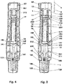
- Längsschnitt des Einmalinjektors aus
Figur 1 ; - Figur 4:
- Längsschnitt normal zu
Figur 3 ; - Figur 5:
- Querschnitt des Einmalinjektors oberhalb des Auslöserings;
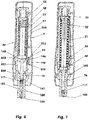
- Figur 6:
- Einmalinjektor nach dem Auslösen;
- Figur 7:
- Einmalinjektor mit entleerter Zylinder-Kolben-Einheit;
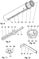
- Figur 8:
- Dimetrische Ansicht des Gehäuses;
- Figur 9:
- Dimetrische Ansicht des Kolbenbetätigungsstempels;
- Figur 10:
- Dimetrische Ansicht des Auslöserings;
- Figur 11:
- Dimetrische Darstellung der Stützscheibe;
- Figur 12:
- Dimetrische Darstellung des Stützstabs;
- Figur 13:
- Detail der Auslösevorrichtung vor dem Auslösen;
- Figur 14:
- Detail der Auslösevorrichtung nach dem Auslösen.
- Die
Figuren 1 - 14 zeigen einen Einmal- oder Einweginjektor (4). Derartige Injektoren (4) werden zum einmaligen Einbringen einer in einer Zylinder-Kolben-Einheit (100) gelagerten Injektionslösung (1) oder eines Lösemittels in die Haut eines Patienten eingesetzt. - Der Einweginjektor (4) umfasst ein Mantelgehäuse (82), in dem ein inneres Gehäuse (10) mit einem Kolbenbetätigungsstempel (60) und einer Schraubendruckfeder (50) als dauergeladener Federenergiespeicher (50) sowie eine Zylinder-Kolben-Einheit (100) angeordnet sind. Die Zylinder-Kolben-Einheit (100) ist mittels einer Schutzkappe (120) verschlossen. Das Auslösen des Einmalinjektors (4) wird mittels eines Sicherungsschiebers (87) verhindert. Dieser kann zur Entsicherung herausnehmbar sein oder er kann im Einmalinjektor (4) geführt verschiebbar sein. Das Gehäuse (10) und das Mantelgehäuse (82) sind beispielsweise aus Kunststoff hergestellt. Dies kann ein thermo- oder duroplastischer Werkstoff, z.B. POM, ABS, etc. sein.
- Das Mantelgehäuse (82) besteht im Ausführungsbeispiel aus einer Oberschale (220) und einer Unterschale (230). Die beiden Schalen (220, 230) sind mittels Zapfenverbindungen (228, 238) miteinander verbunden und beispielsweise form-und/oder stoffschlüssig gesichert. Die Oberschale (220) und die Unterschale (230) können beispielsweise miteinander verklebt, verschweißt, etc. sein. Die Oberschale (220) und die Unterschale (230) können auch miteinander verrastet sein.
- Das im Querschnitt polygonförmige Mantelgehäuse (82) hat im Ausführungsbeispiel einen zumindest annährend regelmäßigen, dreiecksähnlichen Querschnitt, vgl.
Figur 5 . Die Querschnittsfläche im hinteren, der Injektionsstelle abgewandten Bereich des Einweginjektors (4) beträgt 70 % der Querschnittsfläche im vorderen, der Injektionsstelle zugewandten Bereich des Einweginjektors (4). Der stetige Anstieg der Querschnittsfläche liegt, vom Bediener aus gesehen, im dritten Viertel der Länge des Einweginjektors (4). - Der Einweginjektor (4) umfasst ein rohrförmig ausgebildetes Gehäuse (10), in dem ein Federenergiespeicher (50) und ein Kolbenbetätigungsstempel (60) angeordnet sind. Im vorderen, der Injektionsstelle zugewandten Bereich hat das Gehäuse (10) nach innen ragende Federhaken (42). In die Federhaken (42) ist in den Darstellungen der
Figuren 3 und 4 die z.B. vorbefüllte Zylinder-Kolben-Einheit (100) eingesetzt und verrastet. - Das Gehäuse (10) hat eine weitgehend zylindrische Innenkontur. Im hinteren, der Injektionsstelle abgewandten Bereich ist ein Innengewinde (11) angeordnet. In diesem sitzt eine Abstützschraube (12) mit einem Sechskantabschnitt (13). Die Außenkontur des Gehäuses (10) hat eine zylinderförmige Grundform mit einer Abflachung (14), vgl.
Figur 2 . Im Bereich der Abflachung (14) liegt ein Stützstab (21) am Gehäuse (10) an. Der Stützstab (21) ragt mit einem Klemmschenkel (25) in einen oberen Schlitz (16) des Gehäuses (10). Ein Umgriffshaken (26) des Stützstabs (21) ragt durch eine untere Öffnung (18) mit rechteckiger Querschnittsfläche (18) in das Gehäuse (10). Gegenüber der Abflachung (14) weist das Gehäuse (10) eine in der Längsrichtung (5) des Einmalinjektors (4) orientierte Führungsrippe (15) auf, vgl. dieFiguren 5 und8 . - Der Kolbenbetätigungsstempel (60) umfasst einen z.B. zylindrischen Führungszapfen (62), einen Stempelteller (73) und einen Kolbenschieber (76). Der Führungszapfen (62) trägt und führt den Federenergiespeicher (50), der hier als Schraubendruckfeder (50) ausgebildet ist. Das in den
Figuren 3 und 4 obere Ende der Schraubendruckfeder (50) stützt sich über eine Scheibe (38) und den Klemmschenkel (25) des Stützstabs (21) an der Abstützschraube (12) ab. Der Führungszapfen (62) hat in radialer Richtung orientierte kreissegmentförmige Aussparungen (66). Der Einweginjektor (4) kann auch ohne die Stützscheibe (38) ausgeführt sein. - Der Stempelteller (73) des Kolbenbetätigungsstempels (60) ist scheibenförmig ausgebildet und normal zur Mittellängsachse (7) des Einweginjektors (4) ausgerichtet. Er hat eine der Schraubendruckfeder (50) abgewandte, konisch ausgebildete Bundfläche (75). Der Spitzenwinkel des gedachten Kegels der Bundfläche (75) beträgt z.B. 160 Grad.
- An dieser Bundfläche (75) liegt eine Stützscheibe (160) an, vgl.
Figur 11 . Im Ausführungsbeispiel ist die Stützscheibe (160) eine Lochscheibe und hat um die zentrale Bohrung herum angeordnete Nuten (163) und Keile (162), mit denen sie formschlüssig auf dem Kolbenschieber (76) des Kolbenbetätigungsstempels (60) sitzt. Die Stützscheibe (160) ist in der Seitenansicht kegelstumpfförmig ausgebildet. Sie ist beispielsweise aus einem metallischen Werkstoff, z.B. einem austenitischen, korrosionsbeständigen Stahl, hergestellt. In der Darstellung derFigur 3 ist sie mittels des Umgriffshakens (26) des Stützstabs (21) in ihrer Position gesichert. - Der stangenartig ausgebildete Kolbenschieber (76) hat im Ausführungsbeispiel eine zumindest annähernd zylindrische Gestalt. Beispielsweise weist er in Längsrichtung des Einmalinjektors (4) ausgerichtete Schlüsselflächen (77) auf. Entlang dieser Schlüsselflächen (77) kann beim Eintauchen des Kolbenschiebers (76) in die Zylinder-Kolben-Einheit (100) Luft schneller entweichen.
- Der Stützstab (21), vgl. die
Figuren 2 ,3 und12 , ist aus einem Blechstreifen mit z.B. konstanter rechteckiger Querschnittsfläche hergestellt. Die Breite des Stützstabes (21) normal zur Längsrichtung (5) des Einmalinjektors (4) ist im Ausführungsbeispiel acht Mal so groß wie seine Dicke. Der Werkstoff des Stützstabes (21) ist ein austenitischer Federstahl. Sein Elastizitätsmodul ist beispielsweise größer als 190.000 Newton pro Quadratmillimeter. Der Stützstab (21) umfasst einen Hauptschenkel (27), den Klemmschenkel (25) und den Umgriffshaken (26). In der Darstellung derFigur 3 liegt der Hauptschenkel (27) parallel zur Abflachung (14). Seine Länge beträgt beispielsweise dem Siebenfachen der Breite des Stützstabs (21). Das hintere, in derFigur 3 oben dargestellte Ende des Stützstabes (21) zeigt in Richtung des Innenraums (17) des Einweginjektors (4) und bildet den Klemmschenkel (25). Der z.B. durch ein Biegeumformverfahren abgewinkelte Klemmschenkel (25) schließt mit dem Hauptschenkel (27) einen Winkel von z.B. 92 Grad ein. - Das vordere, in der
Figur 3 untere Ende des Stützstabs (21) zeigt ebenfalls in Richtung des Innenraums (17) und bildet den Umgriffshaken (26). Der Umgriffshaken (26) schließt mit dem Hauptschenkel (27) einen Winkel ein, der um den Neigungswinkel der Bundfläche (75) zu einer Normalenebene der Mittenlängsachse (7) des Einmalinjektors (4) größer ist als ein rechter Winkel. Die Länge des Umgriffshakens (26) beträgt beispielsweise 20 % der Länge des Klemmschenkels (25). - Die Zylinder-Kolben-Einheit (100) umfasst einen z.B. transparenten Zylinder (101) und einen im Zylinder (101) geführten Kolben (111). In den Darstellungen der
Figuren 3, 4 und6 sitzt der Kolben (111) in einer hinteren Position. Zwischen dem Kolben (111) und dem, ebenfalls im Zylinder (101) geführten Kolbenschieber (76) liegt ein Zwischenraum (141). Seine Länge beträgt im Ausführungsbeispiel zwei Millimeter. Diese Länge kann zwischen einem Millimeter und zehn Millimeter betragen. - Die in den
Figuren 3, 4 ,6 und 7 unten liegende Austrittsöffnung (106) der Zylinder-Kolben-Einheit (100) ist als kurze, zylindrische, düsenartige Bohrung (106) ausgebildet. - In den Darstellungen der
Figuren 3, 4 ,6 und 7 ist die Zylinder-Kolben-Einheit (100) in das Gehäuse (10) eingesetzt. Die Federhaken (42) hintergreifen den oberen Bund (108) der Zylinder-Kolben-Einheit (100). Auf den Federhaken (42) sitztunterhalb der Ebene des unteren Endes des Bundes (108) - ein Sicherungsring (250). Dieser Sicherungsring (250) hat im Ausführungsbeispiel eine kreisförmige Grundfläche. Sein Innendurchmesser ist beispielsweise größer als der Außendurchmesser des Gehäuses (10) im Bereich der unverformten Federhaken (42). Sein Außendurchmesser ist z.B. größer als der Innendurchmesser des Mantelgehäuses (82) und kleiner als der Außendurchmesser der Verschlusskappe (120). - Auf dem Gehäuse (10) sitzt ein Auslösering (190). Dieser ist als Einzelteil in der
Figur 10 dargestellt. Seine Mantelfläche weist einen oberen zylindrischen Abschnitt (192) und einen unteren Abschnitt (191) auf. Der untere Abschnitt (191) ist bereichsweise zylindrisch und bereichsweise kegelstumpfförmig ausgebildet. Die in der Grundform zylinderförmige Innenwandung (193) hat auf der einen Seite eine in Längsrichtung (5) des Einweginjektors (4) orientierte Verdrehsicherungsnut (194). Auf der gegenüberliegenden Seite ist eine schräg ausgebildete Anlagefläche (195) ausgebildet. Diese Anlagefläche (195) ist beispielsweise in einem Winkel von 20 Grad zur Längsrichtung (5) des Einmalinjektors (4) ausgerichtet. Dieser Winkel, dessen Spitze in der Auslöserichtung (6) des Einweginjektors (4) versetzt zum Auslösering (190) liegt, kann zwischen 10 Grad und 45 Grad betragen. Die Anlagefläche (195) endet an einem unteren Absatz (197). Im Bereich dieses unteren Absatzes (197) ist die Innenwandung durch eine Sehne der Grundform begrenzt. - Auf der Anlagefläche (195) liegt im Ausführungsbeispiel ein als Gleitplatte (196) ausgebildetes Einschubblech (196). Der Einweginjektor (4) kann jedoch auch ohne das Einschubblech (196) ausgeführt sein. Das Einschubblech (196) besteht beispielsweise aus einem korrosionsfesten austenitischen Stahl. Der Elastizitätsmodul dieses Werkstoffs ist größer als 190.000 Newton pro Quadratmillimeter. Die Gleitplatte (196) steht auf dem Absatz (197) auf. Vor dem Auslösen des Einmalinjektors (4), vgl.
Figur 3 und13 , ist der Stützstab (21) an der Gleitplatte (196) abgestützt. Er ist damit indirekt an der Anlagefläche (195) abgestützt. Die Haftreibungszahl dieser Werkstoffkombination ist beispielsweise geringer als 0,2. Auch bei längerer Lagerung verursacht der druckbelastete Stützstab (21) keine Verformungen der Gleitplatte (196). Damit ist auch nach längerer Lagerzeit ein sicheres Auslösen gewährleistet. - Die beiden Schalen (220, 230) der Auslösehülse (82) haben an ihrer Innenseite jeweils Verstärkungsrippen (221 - 227; 231 - 237). Diese Querrippen (221 -227; 231 - 237) sind normal zur Längsrichtung (5) des Einmalinjektors (4) orientiert. Hierbei weisen die hinteren Verstärkungsrippen (223 - 227; 232 - 237) jeweils zwei Teile auf, zwischen denen eine Nut (239) angeordnet ist. Die dem Bediener abgewandten vordersten Verstärkungsrippen (221, 222; 231) sind jeweils unterbrechungsfrei ausgeführt. Die Oberschale (220) und die Unterschale (230) sind mittels mehrerer Zapfenverbindungen (228, 238) miteinander verbunden. Hierbei weist im Ausführungsbeispiel die Oberschale (220) an der Trennfuge sechs Zapfen (228) auf, die in Zapfenlöcher (238) der Unterschale (230) eingreifen. Gegebenenfalls können die Zapfenverbindungen (228, 238) bei der Montage miteinander verrasten. Auch ein Verkleben der Unterschale (230) mit der Oberschale (220) ist denkbar.
- Bei der Montage des Einmalinjektors (4) wird beispielsweise zunächst die Stützscheibe (160) auf den Kolbenschieber (76) des Kolbenbetätigungsstempels (60) aufgeschoben. Die Schraubenfeder (50) wird auf den Führungszapfen (62) des Kolbenbetätigungsstempels (60) aufgesetzt. Der Auslösering (190) wird, geführt an der Abflachung (14) und an der Führungsrippe (15), von hinten auf das Gehäuse (10) aufgeschoben, bis er unterhalb der rechteckigen Aussparung (18) liegt. Beispielsweise kann die Gleitplatte (196) bereits in den Auslösering (190) eingelegt und fixiert sein. Eine ringförmige Gehäuseaufweitung (19) verhindert das weitere Wandern oder Verschieben des Auslöserings (190) nach unten. Nach dem Einführen des Klemmschenkels (25) des Stützstabs (21) in den oberen Gehäuseschlitz (16) wird die Scheibe (38) von unten in das Gehäuse (10) eingelegt. Die Dicke der Scheibe (38) kann je nach erforderlicher Federvorspannung ausgewählt werden. Hiernach werden die vormontierten Teile (50, 60, 160) ebenfalls von unten in das Gehäuse (10) eingeführt, sodass die Schraubendruckfeder (50) an der Druckscheibe (38) anliegt und diese den Klemmschenkel (25) kontaktiert.
- Nun kann die Abstützschraube (12) eingeschraubt werden, bis sie am Klemmschenkel (25) anliegt oder gegen diesen presst. Gegebenenfalls kann der Gewindegang (213) der Abstützschraube (12) und/oder des Gehäuses (10) eine Planverzahnung aufweisen, um ein unbeabsichtigtes Lösen der Abstützschraube (12) zu verhindern. Der Kolbenbetätigungsstempel (60) wird z.B. mittels eines Werkzeugs eingedrückt. Hierbei wird die Schraubendruckfeder (50) gespannt. Beispielsweise wird das Gehäuse (10) hierbei an einem Haltering (211) gehalten. Der Umgriffshaken (26) des Stützstabs (21) wird in die rechteckige Aussparung (18) eingeführt und an die Unterseite (161) der Stützscheibe (160) angelegt. Der Auslösering (190) wird nach oben gezogen, bis er am Stützstab (21) anliegt. Der Stützstab (21) stützt sich nun an der Gleitplatte (196) ab, vgl.
Figur 13 . Zur Sicherung der Montageposition kann ein z.B. u-förmiger Bügel in Montageöffnungen (212) des Gehäuses (10) eingeführt werden. Dieser Bügel sichert die Lage des Auslöserings (190) nach dem Abnehmen der Spannvorrichtung des Federenergiespeichers (50). Diese Vormontagegruppe kann nun z.B. an einen weiteren Arbeitsplatz gefördert werden. Es besteht keine Gefahr eines unbeabsichtigten Auslösens. - Im unteren Bereich des Einmalinjektors (4) wird der Sicherungsring (250) auf die Federhaken (42) aufgeschoben, bis er beispielsweise am Haltering (211) anliegt. Nun kann die z.B. vorbefüllte Zylinder-Kolben-Einheit (100) in das Gehäuse (10) eingesetzt werden und in diesem verrastet werden. Der Sicherungsring (250) wird nach vorne gezogen und sichert so die Lage der Zylinder-Kolben-Einheit (100).
- Die Vormontagegruppe mit dem Gehäuse (10) und der Zylinder-Kolben-Einheit (100) kann nun weitergefördert oder behandelt werden.
- Bei der Endmontage wird diese Vormontagegruppe beispielsweise in die Unterschale (230) eingelegt. Hierbei wird die Rippe (15) des Gehäuses (10) in der Längsnut (239) der Unterschale (230) zentriert. Der Auslösering (190) liegt zwischen den zweiten Querrippen (222, 232) und den dritten Querrippen (223, 233). Der Kopf der Abstützschraube (12) ragt über die hinterste Querrippe (227; 237) heraus. Die Verschlusskappe (120) sitzt außerhalb des Mantelgehäuses (82). Das Sicherungselement (87) wird in den Schlitz (241) der Unterschale (230) eingeführt und z.B. zwischen der Abstützschraube (12) und dem Gehäuse (82) geklemmt. Die Abstützschraube (12) kann gegen weiteres Verdrehen z.B. formschlüssig gesichert werden. Gegebenenfalls kann eine zusätzliche Druckfeder zwischen der Abstützschraube (12) und der Hülse (82) den Widerstand gegen versehentliches Auslösen erhöhen. Diese Feder bestimmt auch den Widerstand des Einweginjektors (4) beim Auslösen. Der u-förmige Bügel kann entfernt werden.
- Zum Abschluss der Montage wird die Oberschale (220) auf die Unterschale (230) aufgesetzt und z.B. durch Verkleben, Verrasten, etc. gesichert. Nun kann ein zusätzlicher Originalitätsverschluss, z.B. eine Banderole, über das Mantelgehäuse (82) und die Verschlusskappe (120) angebracht werden. An ihrer Umfangsfläche (122) weist sie eine Riffelung (123) auf, um ein Abrutschen der Finger zu vermeiden.
- Es ist auch denkbar, die Montage in einer anderen als in der beschriebenen Reihenfolge durchzuführen.
- Der fertig montierte Einweginjektor (4) kann nun verpackt und vertrieben werden. Wird er z.B. nach dem Auspacken auf einem Tisch abgelegt, besteht aufgrund der Gehäusegeometrie keine Gefahr des Wegrollens.
- Vor dem Einsatz des Einmalinjektors (4) wird zunächst der Originalitätsverschluss entfernt. Nach dem Abnehmen der Verschlusskappe (120) kann das Sicherungselement (87) herausgezogen werden. Der Einmalinjektor (4) ist nun einsatzbereit und wird beispielsweise auf die Haut des Patienten aufgesetzt. Beispielsweise haftet die Stirnfläche (103) der Zylinder-Kolben-Einheit (100) an der Haut des Patienten an. Auch in diesem Zustand verhindert die Selbsthemmung zwischen dem Stützstab (21) und dem Auslösering (190) ein unbeabsichtigtes Selbstauslösen des Einweginjektors (4), vgl. die
Figur 13 . - Zum Auslösen des Einmalinjektors (4) wird das Mantelgehäuse (82), das eine Auslösehülse (82) bildet, in der Auslöserichtung (6) nach vorne, also in Richtung der Haut des Patienten verschoben. Die Auslösehülse (80) verschiebt hierbei den Auslösering (190) relativ zum Gehäuse (10) in den Schnittdarstellungen der
Figuren 3, 4 ,6 und 7 nach unten. In derFigur 6 ist der nichtstatische Zustand unmittelbar nach dem Auslösen dargestellt. Der Federenergiespeicher (50) drückt den Stempelteller (73) nach vorne. Hierbei verdrängt die Druckscheibe (160) den Umgriffshaken (26) des Stützstabs (21). Der Stützstab (21) gleitet entlang der Gleitplatte (196) nach außen und gibt damit den Kolbenbetätigungsstempel (60) vollständig frei. Hierbei kann der Stützstab (21) gegebenenfalls auf eine dämmende Gummischicht auftreffen. Der Kolbenbetätigungsstempel (60) schnellt, belastet von dem sich entspannenden Federenergiespeicher (50), nach vorne bzw. unten. Der Kolbenschieber (76) schlägt auf den Kolben (111) und schiebt diesen nach vorne. Hierbei wird die Luft aus dem Zwischenraum (141) entlang der Schlüsselflächen (77) verdrängt. Die im Zylinder (101) gelagerte Injektionslösung (1) wird durch die Austrittsöffnung (106) und die Hornhaut des Patienten hindurch in den Körper des Patienten verdrängt. - Die
Figuren 7 und14 zeigen den Einmalinjektor (4) nach dem Auslösen. Der Auslösering (190) ist relativ zum Gehäuse (10) nach unten verschoben. Der Stützstab (21) ist nach außen verdrängt. Hierbei blockiert er z.B. das Wiedereinschieben der Auslösehülse (82) mit dem Auslösering (190). Der Federenergiespeicher (50) ist entspannt. Der Kolbenbetätigungsstempel (60) liegt in seiner vorderen Endlage. Die Zylinder-Kolben-Einheit (100) ist entleert. - Selbstverständlich ist es auch denkbar, die verschiedenen genannten Ausführungsformen miteinander zu kombinieren.
-
- 1
- Injektionslösung, Wasser für Injektionszwecke
- 4
- Einmalinjektor, Einweginjektor
- 5
- Längsrichtung
- 6
- Auslöserichtung
- 7
- Mittellängsachse
- 10
- Gehäuse
- 11
- Innengewinde
- 12
- Abstützschraube
- 13
- Sechskantabschnitt
- 14
- Abflachung
- 15
- Führungsrippe
- 16
- Gehäuseöffnung, schlitzförmig
- 17
- Innenraum
- 18
- Gehäuseöffnung mit rechteckigem Querschnitt
- 19
- Gehäuseaufweitung
- 21
- Stützstab, Sperrstab
- 25
- Klemmschenkel
- 26
- Umgriffshaken
- 27
- Hauptschenkel
- 38
- Scheibe
- 42
- Federhaken
- 50
- Federenergiespeicher, Schraubendruckfeder, Feder
- 60
- Kolbenbetätigungsstempel
- 62
- Führungszapfen
- 66
- Aussparungen
- 73
- Stempelteller
- 75
- Bundfläche
- 76
- Kolbenschieber
- 77
- Schlüsselflächen
- 80
- Auslöseeinheit
- 82
- Auslöseelement, Auslösehülse
- 87
- Sicherungsschieber, Sicherungselement
- 100
- Zylinder-Kolben-Einheit
- 101
- Zylinder
- 103
- Stirnfläche
- 106
- Bohrung, Austrittsöffnung
- 108
- Bund
- 111
- Kolben
- 120
- Verschlusskappe
- 122
- Umfangsfläche
- 123
- Riffelung
- 141
- Zwischenraum
- 160
- Stützscheibe, Druckscheibe
- 161
- Unterseite
- 162
- Keile
- 163
- Nuten
- 190
- Auslösering
- 191
- unterer Bereich
- 192
- zylinderförmiger Bereich
- 193
- Innenwandung
- 194
- Verdrehsicherungsnut
- 195
- Anlagefläche
- 196
- Einschubblech, Gleitplatte
- 197
- Absatz
- 211
- Haltering
- 212
- Montageöffnungen
- 213
- Gewindegang
- 220
- Oberschale
- 221, 222
- Verstärkungsrippen, Querrippen, einteilig
- 223 - 227
- Verstärkungsrippen, Querrippen, zweiteilig
- 228
- Zapfen
- 230
- Unterschale
- 231
- Verstärkungsrippe, Querrippe, einteilig
- 232 - 237
- Verstärkungsrippe, Querrippe, zweiteilig
- 238
- Zapfenlöcher
- 239
- Längsnut
- 241
- Schlitz
- 250
- Sicherungsring
Claims (8)
- Einweginjektor (4) mit einem in einem Gehäuse (10) gelagerten, mittels eines Federenergiespeichers (50) belasteten und mittels einer verschiebbaren Auslösevorrichtung (80) entsperrbaren Kolbenbetätigungsstempel (60), wobei der Kolbenbetätigungsstempel (60) mittels eines im Gehäuse (10) gelagerten Zugstabs (21) abstützbar ist,
dadurch gekennzeichnet,- dass die Auslösevorrichtung (80) einen relativ zum Gehäuse (10) verschiebbaren Auslösering (190) umfasst,- dass der Zugstab (21) mittels einer Anlagefläche (195) des Auslöserings (190) direkt oder indirekt abstützbar ist und- dass die Anlagefläche (195) mit der Längsrichtung (5) des Einweginjektors (4) einen Winkel zwischen 10 Grad und 45 Grad einschließt, wobei der Scheitel des Winkels in der Auslöserichtung (6) des Einweginjektors (4) versetzt zum Auslösering (190) liegt. - Einweginjektor (4) nach Anspruch 1,
dadurch gekennzeichnet,
dass der Auslösering (190) in einer Auslösehülse (82) der Auslösevorrichtung (80) gelagert ist. - Einweginjektor (4) nach Anspruch 1,
dadurch gekennzeichnet,
dass der Auslösering (190) und das Gehäuse (10) verdrehsicher zueinander ausgebildet sind. - Einweginjektor (4) nach Anspruch 1,
dadurch gekennzeichnet,
dass die Anlagefläche (195) eine Gleitplatte (196) trägt. - Einweginjektor (4) nach Anspruch 1,
dadurch gekennzeichnet,
dass der Zugstab (21) einstreifig ausgebildet ist. - Einweginjektor (4) nach Anspruch 1,
dadurch gekennzeichnet,
dass der Zugstab (21) mittels eines Klemmschenkels (25) im Gehäuse (10) gelagert ist. - Einweginjektor (4) nach Anspruch 6,
dadurch gekennzeichnet,
dass der Klemmschenkel (25) im Gehäuse (10) mittels einer im Gehäuse (10) befestigten Abstützschraube (12) fixiert ist. - Einweginjektor (4) nach Anspruch 1,
dadurch gekennzeichnet,
dass die Relativbewegung zwischen der Auslösevorrichtung (80) und dem Gehäuse (10) mittels eines lösbaren oder entriegelbaren Sicherungselements (87) blockierbar ist.
Applications Claiming Priority (1)
| Application Number | Priority Date | Filing Date | Title |
|---|---|---|---|
| PCT/EP2015/059714 WO2016177393A1 (de) | 2015-05-04 | 2015-05-04 | Einweginjektor mit erhöhter auslösesicherheit |
Publications (2)
| Publication Number | Publication Date |
|---|---|
| EP3291863A1 EP3291863A1 (de) | 2018-03-14 |
| EP3291863B1 true EP3291863B1 (de) | 2019-03-13 |
Family
ID=53039913
Family Applications (1)
| Application Number | Title | Priority Date | Filing Date |
|---|---|---|---|
| EP15720087.4A Not-in-force EP3291863B1 (de) | 2015-05-04 | 2015-05-04 | Einweginjektor mit erhöhter auslösesicherheit |
Country Status (8)
| Country | Link |
|---|---|
| US (1) | US10888658B2 (de) |
| EP (1) | EP3291863B1 (de) |
| JP (1) | JP6617158B2 (de) |
| CN (1) | CN107206179B (de) |
| BR (1) | BR112017022400A2 (de) |
| CA (1) | CA2973396A1 (de) |
| ES (1) | ES2729864T3 (de) |
| WO (1) | WO2016177393A1 (de) |
Families Citing this family (1)
| Publication number | Priority date | Publication date | Assignee | Title |
|---|---|---|---|---|
| AU2019208338B2 (en) | 2018-01-19 | 2024-11-07 | Birya Biotech, Inc. | Tool for servicing an auto-injector |
Family Cites Families (18)
| Publication number | Priority date | Publication date | Assignee | Title |
|---|---|---|---|---|
| JP3487856B2 (ja) * | 1993-07-31 | 2004-01-19 | ウェストン メディカル リミテッド | 無針注射器 |
| FR2733155B1 (fr) * | 1995-04-18 | 1997-09-19 | Tebro | Auto-injecteur rechargeable |
| US6234996B1 (en) * | 1999-06-23 | 2001-05-22 | Percusurge, Inc. | Integrated inflation/deflation device and method |
| GB0007071D0 (en) * | 2000-03-24 | 2000-05-17 | Sams Bernard | One-way clutch mechanisms and injector devices |
| US20030105430A1 (en) * | 2001-11-30 | 2003-06-05 | Elan Pharma International Limited Wil House | Automatic injector |
| CH696421A5 (de) * | 2003-12-18 | 2007-06-15 | Tecpharma Licensing Ag | Autoinjektor mit Arretierung des Wirkstoffbehälters. |
| CN101854965B (zh) * | 2007-09-25 | 2013-02-13 | 贝克顿迪金森法国公司 | 具有可通过防护罩的运动定位在激活位置的触发装置和激活位置的指示的自动注射装置 |
| EP2237817B1 (de) * | 2007-11-14 | 2019-02-13 | SHL Group AB | Automatisches injektionsgerät mit aktiv ausgelöstem spritzenrückzug |
| GB2461087B (en) * | 2008-06-19 | 2012-09-26 | Cilag Gmbh Int | Injection device |
| DE102008048595A1 (de) * | 2008-09-23 | 2010-04-01 | Lts Lohmann Therapie-Systeme Ag | Einweginjektor mit hoher Injektionssicherheit |
| DE102008063517A1 (de) * | 2008-12-18 | 2010-07-01 | Lts Lohmann Therapie-Systeme Ag | Einmalinjektor mit einem biegeelastischen Gehäuse II |
| DE102008063519A1 (de) | 2008-12-18 | 2010-07-01 | Lts Lohmann Therapie-Systeme Ag | Einmalinjektor mit einem biegeelastischen Metallgehäuse |
| WO2011101383A1 (en) * | 2010-02-22 | 2011-08-25 | Sanofi-Aventis Deutschland Gmbh | Force transmission arrangement for auto-injector |
| US9320855B2 (en) * | 2011-02-03 | 2016-04-26 | Shl Group Ab | Medicament delivery device |
| US9717851B2 (en) | 2012-05-25 | 2017-08-01 | Aptar France Sas | Autoinjector |
| US9662447B2 (en) * | 2012-05-25 | 2017-05-30 | Aptar France Sas | Autoinjector |
| CA2908507C (en) * | 2013-03-25 | 2018-05-01 | Carebay Europe Ltd | Medicament delivery device comprising a locking mechanism |
| GB2521212B (en) * | 2013-12-13 | 2016-07-27 | Owen Mumford Ltd | Selectable dose injection device |
-
2015
- 2015-05-04 CN CN201580075124.9A patent/CN107206179B/zh not_active Expired - Fee Related
- 2015-05-04 JP JP2017557304A patent/JP6617158B2/ja not_active Expired - Fee Related
- 2015-05-04 ES ES15720087T patent/ES2729864T3/es active Active
- 2015-05-04 CA CA2973396A patent/CA2973396A1/en not_active Abandoned
- 2015-05-04 BR BR112017022400-3A patent/BR112017022400A2/pt not_active IP Right Cessation
- 2015-05-04 WO PCT/EP2015/059714 patent/WO2016177393A1/de not_active Ceased
- 2015-05-04 EP EP15720087.4A patent/EP3291863B1/de not_active Not-in-force
-
2017
- 2017-10-25 US US15/793,295 patent/US10888658B2/en active Active
Non-Patent Citations (1)
| Title |
|---|
| None * |
Also Published As
| Publication number | Publication date |
|---|---|
| BR112017022400A2 (pt) | 2018-07-10 |
| US20180056000A1 (en) | 2018-03-01 |
| WO2016177393A1 (de) | 2016-11-10 |
| ES2729864T3 (es) | 2019-11-06 |
| CN107206179B (zh) | 2020-06-19 |
| CA2973396A1 (en) | 2016-11-10 |
| JP6617158B2 (ja) | 2019-12-11 |
| EP3291863A1 (de) | 2018-03-14 |
| JP2018514317A (ja) | 2018-06-07 |
| CN107206179A (zh) | 2017-09-26 |
| US10888658B2 (en) | 2021-01-12 |
Similar Documents
| Publication | Publication Date | Title |
|---|---|---|
| EP2745866B1 (de) | Auslösesicherung für einen autoinjektor | |
| EP2323717B1 (de) | Automatische injektionsvorrichtung für die verabreichung einer festen dosis | |
| EP2139542B1 (de) | Einweginjektor mit mindestens einem zughaken und einem schiebekeilgetriebe zum entsichernden lösen eines sperrelements | |
| EP2121082B1 (de) | Einweginjektor mit mindestens einem zughaken | |
| DE102004064159B4 (de) | Autoinjektor mit Arretierung des Wirkstoffbehälters | |
| EP2341960B1 (de) | Nadelloser einweginjektor mit hoher injektionssicherheit | |
| DE102007008369A1 (de) | Einweginjektor mit mindestens einem zentralen Zugstab | |
| WO2004047893A1 (de) | Autoinjektor mit rückstellbarer auslösesicherung | |
| DE102007013837A1 (de) | Federanordnung in einer Injektionsvorrichtung | |
| EP2162171B1 (de) | Einweginjektor mit mindestens einem zughaken | |
| EP2892591B1 (de) | Einmalinjektor mit zweistufiger auslösung | |
| EP2078535A1 (de) | Implantatspritze | |
| WO2016177390A1 (de) | Einmalinjektor mit schalldämmschicht | |
| EP3291858B1 (de) | Einweginjektor mit einer auslösemontageeinheit zum vereinfachten zusammenbau | |
| WO2016177393A1 (de) | Einweginjektor mit erhöhter auslösesicherheit | |
| CH696423A5 (de) | Autoinjektor. | |
| EP2563428B1 (de) | Einmalinjektor mit biegeelastischem kolbenbetätigungsstempel | |
| EP4487897B1 (de) | Implantatspritze | |
| WO2014033175A2 (de) | Zylinder-kolben-einheit mit zweiteiligem kolben | |
| DE202024102228U1 (de) | Viehbetäubungsvorrichtung | |
| CH696738A5 (de) | Autoinjektor. | |
| EP2570144B1 (de) | Nadelloser Einweginjektor mit Elementen zur Erhöhung der Auslösesicherheit | |
| DE102008064985B4 (de) | Automatische Injektionsvorrichtung für die Verabreichung einer festen Dosis | |
| DE1478837A1 (de) | Bolzensetzgeraet zum Eintreiben von Bolzen od.dgl. in Bauteile | |
| EP4085945A1 (de) | Autoinjektor mit verbesserter co2 bilanz |
Legal Events
| Date | Code | Title | Description |
|---|---|---|---|
| STAA | Information on the status of an ep patent application or granted ep patent |
Free format text: STATUS: THE INTERNATIONAL PUBLICATION HAS BEEN MADE |
|
| PUAI | Public reference made under article 153(3) epc to a published international application that has entered the european phase |
Free format text: ORIGINAL CODE: 0009012 |
|
| STAA | Information on the status of an ep patent application or granted ep patent |
Free format text: STATUS: REQUEST FOR EXAMINATION WAS MADE |
|
| 17P | Request for examination filed |
Effective date: 20171106 |
|
| AK | Designated contracting states |
Kind code of ref document: A1 Designated state(s): AL AT BE BG CH CY CZ DE DK EE ES FI FR GB GR HR HU IE IS IT LI LT LU LV MC MK MT NL NO PL PT RO RS SE SI SK SM TR |
|
| AX | Request for extension of the european patent |
Extension state: BA ME |
|
| DAV | Request for validation of the european patent (deleted) | ||
| DAX | Request for extension of the european patent (deleted) | ||
| GRAP | Despatch of communication of intention to grant a patent |
Free format text: ORIGINAL CODE: EPIDOSNIGR1 |
|
| STAA | Information on the status of an ep patent application or granted ep patent |
Free format text: STATUS: GRANT OF PATENT IS INTENDED |
|
| INTG | Intention to grant announced |
Effective date: 20180928 |
|
| GRAS | Grant fee paid |
Free format text: ORIGINAL CODE: EPIDOSNIGR3 |
|
| GRAA | (expected) grant |
Free format text: ORIGINAL CODE: 0009210 |
|
| STAA | Information on the status of an ep patent application or granted ep patent |
Free format text: STATUS: THE PATENT HAS BEEN GRANTED |
|
| AK | Designated contracting states |
Kind code of ref document: B1 Designated state(s): AL AT BE BG CH CY CZ DE DK EE ES FI FR GB GR HR HU IE IS IT LI LT LU LV MC MK MT NL NO PL PT RO RS SE SI SK SM TR |
|
| REG | Reference to a national code |
Ref country code: GB Ref legal event code: FG4D Free format text: NOT ENGLISH |
|
| REG | Reference to a national code |
Ref country code: CH Ref legal event code: EP Ref country code: AT Ref legal event code: REF Ref document number: 1106837 Country of ref document: AT Kind code of ref document: T Effective date: 20190315 |
|
| REG | Reference to a national code |
Ref country code: IE Ref legal event code: FG4D Free format text: LANGUAGE OF EP DOCUMENT: GERMAN |
|
| REG | Reference to a national code |
Ref country code: DE Ref legal event code: R096 Ref document number: 502015008329 Country of ref document: DE |
|
| REG | Reference to a national code |
Ref country code: NL Ref legal event code: MP Effective date: 20190313 |
|
| REG | Reference to a national code |
Ref country code: LT Ref legal event code: MG4D |
|
| PG25 | Lapsed in a contracting state [announced via postgrant information from national office to epo] |
Ref country code: NO Free format text: LAPSE BECAUSE OF FAILURE TO SUBMIT A TRANSLATION OF THE DESCRIPTION OR TO PAY THE FEE WITHIN THE PRESCRIBED TIME-LIMIT Effective date: 20190613 Ref country code: FI Free format text: LAPSE BECAUSE OF FAILURE TO SUBMIT A TRANSLATION OF THE DESCRIPTION OR TO PAY THE FEE WITHIN THE PRESCRIBED TIME-LIMIT Effective date: 20190313 Ref country code: LT Free format text: LAPSE BECAUSE OF FAILURE TO SUBMIT A TRANSLATION OF THE DESCRIPTION OR TO PAY THE FEE WITHIN THE PRESCRIBED TIME-LIMIT Effective date: 20190313 Ref country code: SE Free format text: LAPSE BECAUSE OF FAILURE TO SUBMIT A TRANSLATION OF THE DESCRIPTION OR TO PAY THE FEE WITHIN THE PRESCRIBED TIME-LIMIT Effective date: 20190313 |
|
| PG25 | Lapsed in a contracting state [announced via postgrant information from national office to epo] |
Ref country code: LV Free format text: LAPSE BECAUSE OF FAILURE TO SUBMIT A TRANSLATION OF THE DESCRIPTION OR TO PAY THE FEE WITHIN THE PRESCRIBED TIME-LIMIT Effective date: 20190313 Ref country code: NL Free format text: LAPSE BECAUSE OF FAILURE TO SUBMIT A TRANSLATION OF THE DESCRIPTION OR TO PAY THE FEE WITHIN THE PRESCRIBED TIME-LIMIT Effective date: 20190313 Ref country code: RS Free format text: LAPSE BECAUSE OF FAILURE TO SUBMIT A TRANSLATION OF THE DESCRIPTION OR TO PAY THE FEE WITHIN THE PRESCRIBED TIME-LIMIT Effective date: 20190313 Ref country code: BG Free format text: LAPSE BECAUSE OF FAILURE TO SUBMIT A TRANSLATION OF THE DESCRIPTION OR TO PAY THE FEE WITHIN THE PRESCRIBED TIME-LIMIT Effective date: 20190613 Ref country code: HR Free format text: LAPSE BECAUSE OF FAILURE TO SUBMIT A TRANSLATION OF THE DESCRIPTION OR TO PAY THE FEE WITHIN THE PRESCRIBED TIME-LIMIT Effective date: 20190313 Ref country code: GR Free format text: LAPSE BECAUSE OF FAILURE TO SUBMIT A TRANSLATION OF THE DESCRIPTION OR TO PAY THE FEE WITHIN THE PRESCRIBED TIME-LIMIT Effective date: 20190614 |
|
| PG25 | Lapsed in a contracting state [announced via postgrant information from national office to epo] |
Ref country code: EE Free format text: LAPSE BECAUSE OF FAILURE TO SUBMIT A TRANSLATION OF THE DESCRIPTION OR TO PAY THE FEE WITHIN THE PRESCRIBED TIME-LIMIT Effective date: 20190313 Ref country code: PT Free format text: LAPSE BECAUSE OF FAILURE TO SUBMIT A TRANSLATION OF THE DESCRIPTION OR TO PAY THE FEE WITHIN THE PRESCRIBED TIME-LIMIT Effective date: 20190713 Ref country code: AL Free format text: LAPSE BECAUSE OF FAILURE TO SUBMIT A TRANSLATION OF THE DESCRIPTION OR TO PAY THE FEE WITHIN THE PRESCRIBED TIME-LIMIT Effective date: 20190313 Ref country code: SK Free format text: LAPSE BECAUSE OF FAILURE TO SUBMIT A TRANSLATION OF THE DESCRIPTION OR TO PAY THE FEE WITHIN THE PRESCRIBED TIME-LIMIT Effective date: 20190313 Ref country code: CZ Free format text: LAPSE BECAUSE OF FAILURE TO SUBMIT A TRANSLATION OF THE DESCRIPTION OR TO PAY THE FEE WITHIN THE PRESCRIBED TIME-LIMIT Effective date: 20190313 Ref country code: RO Free format text: LAPSE BECAUSE OF FAILURE TO SUBMIT A TRANSLATION OF THE DESCRIPTION OR TO PAY THE FEE WITHIN THE PRESCRIBED TIME-LIMIT Effective date: 20190313 |
|
| REG | Reference to a national code |
Ref country code: ES Ref legal event code: FG2A Ref document number: 2729864 Country of ref document: ES Kind code of ref document: T3 Effective date: 20191106 |
|
| PG25 | Lapsed in a contracting state [announced via postgrant information from national office to epo] |
Ref country code: SM Free format text: LAPSE BECAUSE OF FAILURE TO SUBMIT A TRANSLATION OF THE DESCRIPTION OR TO PAY THE FEE WITHIN THE PRESCRIBED TIME-LIMIT Effective date: 20190313 Ref country code: PL Free format text: LAPSE BECAUSE OF FAILURE TO SUBMIT A TRANSLATION OF THE DESCRIPTION OR TO PAY THE FEE WITHIN THE PRESCRIBED TIME-LIMIT Effective date: 20190313 |
|
| REG | Reference to a national code |
Ref country code: DE Ref legal event code: R097 Ref document number: 502015008329 Country of ref document: DE |
|
| REG | Reference to a national code |
Ref country code: CH Ref legal event code: PL |
|
| PG25 | Lapsed in a contracting state [announced via postgrant information from national office to epo] |
Ref country code: IS Free format text: LAPSE BECAUSE OF FAILURE TO SUBMIT A TRANSLATION OF THE DESCRIPTION OR TO PAY THE FEE WITHIN THE PRESCRIBED TIME-LIMIT Effective date: 20190713 |
|
| PLBE | No opposition filed within time limit |
Free format text: ORIGINAL CODE: 0009261 |
|
| STAA | Information on the status of an ep patent application or granted ep patent |
Free format text: STATUS: NO OPPOSITION FILED WITHIN TIME LIMIT |
|
| PG25 | Lapsed in a contracting state [announced via postgrant information from national office to epo] |
Ref country code: DK Free format text: LAPSE BECAUSE OF FAILURE TO SUBMIT A TRANSLATION OF THE DESCRIPTION OR TO PAY THE FEE WITHIN THE PRESCRIBED TIME-LIMIT Effective date: 20190313 Ref country code: MC Free format text: LAPSE BECAUSE OF FAILURE TO SUBMIT A TRANSLATION OF THE DESCRIPTION OR TO PAY THE FEE WITHIN THE PRESCRIBED TIME-LIMIT Effective date: 20190313 Ref country code: CH Free format text: LAPSE BECAUSE OF NON-PAYMENT OF DUE FEES Effective date: 20190531 Ref country code: LI Free format text: LAPSE BECAUSE OF NON-PAYMENT OF DUE FEES Effective date: 20190531 |
|
| REG | Reference to a national code |
Ref country code: BE Ref legal event code: MM Effective date: 20190531 |
|
| 26N | No opposition filed |
Effective date: 20191216 |
|
| PG25 | Lapsed in a contracting state [announced via postgrant information from national office to epo] |
Ref country code: LU Free format text: LAPSE BECAUSE OF NON-PAYMENT OF DUE FEES Effective date: 20190504 Ref country code: SI Free format text: LAPSE BECAUSE OF FAILURE TO SUBMIT A TRANSLATION OF THE DESCRIPTION OR TO PAY THE FEE WITHIN THE PRESCRIBED TIME-LIMIT Effective date: 20190313 |
|
| PG25 | Lapsed in a contracting state [announced via postgrant information from national office to epo] |
Ref country code: TR Free format text: LAPSE BECAUSE OF FAILURE TO SUBMIT A TRANSLATION OF THE DESCRIPTION OR TO PAY THE FEE WITHIN THE PRESCRIBED TIME-LIMIT Effective date: 20190313 |
|
| PG25 | Lapsed in a contracting state [announced via postgrant information from national office to epo] |
Ref country code: IE Free format text: LAPSE BECAUSE OF NON-PAYMENT OF DUE FEES Effective date: 20190504 |
|
| PG25 | Lapsed in a contracting state [announced via postgrant information from national office to epo] |
Ref country code: BE Free format text: LAPSE BECAUSE OF NON-PAYMENT OF DUE FEES Effective date: 20190531 |
|
| PGFP | Annual fee paid to national office [announced via postgrant information from national office to epo] |
Ref country code: DE Payment date: 20200520 Year of fee payment: 6 Ref country code: FR Payment date: 20200522 Year of fee payment: 6 |
|
| PGFP | Annual fee paid to national office [announced via postgrant information from national office to epo] |
Ref country code: IT Payment date: 20200528 Year of fee payment: 6 Ref country code: GB Payment date: 20200527 Year of fee payment: 6 |
|
| PGFP | Annual fee paid to national office [announced via postgrant information from national office to epo] |
Ref country code: ES Payment date: 20200728 Year of fee payment: 6 |
|
| PG25 | Lapsed in a contracting state [announced via postgrant information from national office to epo] |
Ref country code: CY Free format text: LAPSE BECAUSE OF FAILURE TO SUBMIT A TRANSLATION OF THE DESCRIPTION OR TO PAY THE FEE WITHIN THE PRESCRIBED TIME-LIMIT Effective date: 20190313 |
|
| REG | Reference to a national code |
Ref country code: AT Ref legal event code: MM01 Ref document number: 1106837 Country of ref document: AT Kind code of ref document: T Effective date: 20200504 |
|
| PG25 | Lapsed in a contracting state [announced via postgrant information from national office to epo] |
Ref country code: MT Free format text: LAPSE BECAUSE OF FAILURE TO SUBMIT A TRANSLATION OF THE DESCRIPTION OR TO PAY THE FEE WITHIN THE PRESCRIBED TIME-LIMIT Effective date: 20190313 Ref country code: HU Free format text: LAPSE BECAUSE OF FAILURE TO SUBMIT A TRANSLATION OF THE DESCRIPTION OR TO PAY THE FEE WITHIN THE PRESCRIBED TIME-LIMIT; INVALID AB INITIO Effective date: 20150504 |
|
| PG25 | Lapsed in a contracting state [announced via postgrant information from national office to epo] |
Ref country code: AT Free format text: LAPSE BECAUSE OF NON-PAYMENT OF DUE FEES Effective date: 20200504 |
|
| REG | Reference to a national code |
Ref country code: DE Ref legal event code: R119 Ref document number: 502015008329 Country of ref document: DE |
|
| GBPC | Gb: european patent ceased through non-payment of renewal fee |
Effective date: 20210504 |
|
| PG25 | Lapsed in a contracting state [announced via postgrant information from national office to epo] |
Ref country code: GB Free format text: LAPSE BECAUSE OF NON-PAYMENT OF DUE FEES Effective date: 20210504 Ref country code: DE Free format text: LAPSE BECAUSE OF NON-PAYMENT OF DUE FEES Effective date: 20211201 |
|
| PG25 | Lapsed in a contracting state [announced via postgrant information from national office to epo] |
Ref country code: FR Free format text: LAPSE BECAUSE OF NON-PAYMENT OF DUE FEES Effective date: 20210531 |
|
| PG25 | Lapsed in a contracting state [announced via postgrant information from national office to epo] |
Ref country code: MK Free format text: LAPSE BECAUSE OF FAILURE TO SUBMIT A TRANSLATION OF THE DESCRIPTION OR TO PAY THE FEE WITHIN THE PRESCRIBED TIME-LIMIT Effective date: 20190313 |
|
| REG | Reference to a national code |
Ref country code: ES Ref legal event code: FD2A Effective date: 20220727 |
|
| PG25 | Lapsed in a contracting state [announced via postgrant information from national office to epo] |
Ref country code: ES Free format text: LAPSE BECAUSE OF NON-PAYMENT OF DUE FEES Effective date: 20210505 |
|
| PG25 | Lapsed in a contracting state [announced via postgrant information from national office to epo] |
Ref country code: IT Free format text: LAPSE BECAUSE OF NON-PAYMENT OF DUE FEES Effective date: 20200504 |
|
| PG25 | Lapsed in a contracting state [announced via postgrant information from national office to epo] |
Ref country code: IT Free format text: LAPSE BECAUSE OF NON-PAYMENT OF DUE FEES Effective date: 20210504 |