EP3290799A1 - Air/gas admittance device for a combustion appliance - Google Patents
Air/gas admittance device for a combustion appliance Download PDFInfo
- Publication number
- EP3290799A1 EP3290799A1 EP17184899.7A EP17184899A EP3290799A1 EP 3290799 A1 EP3290799 A1 EP 3290799A1 EP 17184899 A EP17184899 A EP 17184899A EP 3290799 A1 EP3290799 A1 EP 3290799A1
- Authority
- EP
- European Patent Office
- Prior art keywords
- gas
- air
- pressure
- side wall
- pressure port
- Prior art date
- Legal status (The legal status is an assumption and is not a legal conclusion. Google has not performed a legal analysis and makes no representation as to the accuracy of the status listed.)
- Granted
Links
Images


Classifications
-
- F—MECHANICAL ENGINEERING; LIGHTING; HEATING; WEAPONS; BLASTING
- F23—COMBUSTION APPARATUS; COMBUSTION PROCESSES
- F23N—REGULATING OR CONTROLLING COMBUSTION
- F23N1/00—Regulating fuel supply
- F23N1/002—Regulating fuel supply using electronic means
-
- F—MECHANICAL ENGINEERING; LIGHTING; HEATING; WEAPONS; BLASTING
- F23—COMBUSTION APPARATUS; COMBUSTION PROCESSES
- F23L—SUPPLYING AIR OR NON-COMBUSTIBLE LIQUIDS OR GASES TO COMBUSTION APPARATUS IN GENERAL ; VALVES OR DAMPERS SPECIALLY ADAPTED FOR CONTROLLING AIR SUPPLY OR DRAUGHT IN COMBUSTION APPARATUS; INDUCING DRAUGHT IN COMBUSTION APPARATUS; TOPS FOR CHIMNEYS OR VENTILATING SHAFTS; TERMINALS FOR FLUES
- F23L17/00—Inducing draught; Tops for chimneys or ventilating shafts; Terminals for flues
- F23L17/005—Inducing draught; Tops for chimneys or ventilating shafts; Terminals for flues using fans
-
- F—MECHANICAL ENGINEERING; LIGHTING; HEATING; WEAPONS; BLASTING
- F23—COMBUSTION APPARATUS; COMBUSTION PROCESSES
- F23N—REGULATING OR CONTROLLING COMBUSTION
- F23N1/00—Regulating fuel supply
- F23N1/02—Regulating fuel supply conjointly with air supply
- F23N1/022—Regulating fuel supply conjointly with air supply using electronic means
-
- F—MECHANICAL ENGINEERING; LIGHTING; HEATING; WEAPONS; BLASTING
- F23—COMBUSTION APPARATUS; COMBUSTION PROCESSES
- F23N—REGULATING OR CONTROLLING COMBUSTION
- F23N2225/00—Measuring
- F23N2225/04—Measuring pressure
-
- F—MECHANICAL ENGINEERING; LIGHTING; HEATING; WEAPONS; BLASTING
- F23—COMBUSTION APPARATUS; COMBUSTION PROCESSES
- F23N—REGULATING OR CONTROLLING COMBUSTION
- F23N2900/00—Special features of, or arrangements for controlling combustion
- F23N2900/05181—Controlling air to fuel ratio by using a single differential pressure detector
Definitions
- the present disclosure relates generally to systems and methods for admitting air and fuel to a burner of a combustion appliance, and more particularly to a device and method for delivering an accurate air/fuel ratio to a burner of a combustion appliance.
- the air/fuel ratio used during the operation of a combustion appliance can affect the efficiency and emissions of the combustion appliance.
- Example combustion appliances include furnaces, water heaters, boilers, direct/in-direct make-up air heaters, power/jet burners and any other residential, commercial or industrial combustion appliance.
- the flow of gas is adjusted to set the air/fuel ratio. This is often accomplished by modulating a gas valve to control the pressure and thus the flow of gas to the combustion appliance. In some cases, the gas valve is modulated based on signals from one or more pressure or flow sensors placed in the gas and/or air streams.
- turbulent and/or otherwise non-uniform gas and/or air flows can introduce noise into the pressure or flow sensor signals, which can result in a non-uniform or otherwise non-optimal air/fuel ratio. This can reduce the efficiency and/or increase the emissions of the combustion appliance.
- an improved air/gas admittance device that provides a more uniform gas and/or air flow to reduce sensor noise and thus improve the efficiency and/or emissions of a combustion appliance.
- the present disclosure relates generally to an improved air/gas admittance device that provides a more uniform gas and/or air flow to reduce sensor noise and thus improve the efficiency and/or emissions of a combustion appliance.
- an illustrative air/gas admittance device for use with a combustion unit such as a combustion appliance may include a body having a side wall defining a passageway that extends from an air inlet to an air/gas outlet and a gas pipe having a side wall defining a passageway that extends from a gas inlet to a gas outlet.
- the side wall of the body may have a gas pipe opening that is in fluid communication with the gas outlet of the gas pipe.
- An air flow restrictor may be positioned in the body between the gas pipe opening and the air inlet, and a gas flow restrictor may be positioned in the gas pipe downstream of the gas inlet.
- a first pressure port may be in the side wall of the body, upstream of the gas pipe opening.
- the first pressure port may be configured to be operatively coupled to a first pressure sensor for measuring a pressure of air within the body.
- a second pressure port may be in the side wall of the gas pipe.
- the second pressure port may be configured to be operatively coupled to a second pressure sensor for measuring a pressure of gas within the gas pipe.
- An air flow smoothing insert may be positioned in the body upstream of the first pressure port.
- an air/gas admittance device for use with a combustion unit may comprise a body having a side wall defining a passageway that extends from an air inlet to an air/gas outlet and a gas pipe having a side wall defining a passageway that extends from a gas inlet to a gas outlet.
- the side wall of the body may have a gas pipe opening that is in fluid communication with the gas outlet of the gas pipe.
- An air flow restrictor may be positioned in the body between the gas pipe opening and the air inlet and an air flow smoothing insert may be positioned in the body upstream of the gas pipe opening.
- the device may further comprise a fan in fluid communication with the air/gas outlet. The fan may be configured to generate an under pressure at the air/gas outlet.
- an air/gas admittance device for use with a combustion unit may comprise a body having a side wall defining a passageway that extends from an air inlet to an air/gas outlet and a gas pipe having a side wall defining a passageway that extends from a gas inlet to a gas outlet.
- the side wall of the body may have a gas pipe opening that is in fluid communication with the gas outlet of the gas pipe.
- a first pressure port may be in the side wall of the body, upstream of the gas pipe opening.
- a first pressure sensor may be operatively coupled to the first pressure port for measuring a pressure of air within the body.
- a second pressure port may be in the side wall of the gas pipe.
- a second pressure sensor may be operatively coupled to the second pressure port for measuring a pressure of gas within the gas pipe.
- An air flow smoothing insert may be positioned in the body upstream of the first pressure port.
- a gas control valve may be coupled to the gas inlet.
- a controller may be operatively coupled to the first pressure sensor, the second pressure sensor and the gas control valve. The controller may be configured to use the pressure of air within the body sensed by the first pressure sensor and the pressure of gas within the gas pipe sensed by the second pressure sensor to control the gas valve to produce a desired air/gas mixture at the air/gas outlet.
- Gas valves are often driven by electronic control systems which evaluate feedback signals from pressure and/or flow sensors.
- the pressure sensors may relay pressure readings to a controller which controls a position of the gas valve.
- the position of the gas valve may be adjusted to optimize the air to fuel (A/F) ratio in order to achieve low emissions of CO, NOx and/or to increase efficiency (e.g. save fuel).
- the pressure sensors may be placed to sense pressures before and/or after air and gas restrictors in an air/gas admittance device. Ideally, signals from the pressure signals are stable and largely free of oscillations and/or other noise caused by air or gas flow disturbances in the admittance device.
- Unstable pressure sensor signals can result in a non-uniform or otherwise non-optimal air/fuel ratio, which can reduce the efficiency and/or increase the emissions of the combustion unit.
- the air/gas admittance device described herein provides a more uniform gas and/or air flow, which reduces sensor noise and can improve the efficiency and/or emissions of a downstream combustion unit.
- FIG. 1 is a schematic perspective view of an illustrative gas valve, air/gas admittance device and fan assembly for use with a combustion unit.
- the illustrative assembly 10 includes a gas valve assembly 12 for controlling gas flow to a combustion unit 17 or other similar or difference devices, an air/gas admittance device 14, a fan or blower 16, and a valve controller 18.
- the gas valve assembly 12 may include a valve body that includes an inlet port coupled to a gas source 11, an outlet port configured to be coupled to a portion of the air/gas admittance device 14, and a fluid path or fluid channel extending between the inlet port and the outlet port.
- a valve member may control the flow of gas from the inlet port to the outlet port.
- the gas valve assembly 12 may include one or more actuators to modulate the flow of gas that is provided to the air/gas admittance device 14.
- the valve controller 18 may control the gas valve assembly 12 based on signals from one or more pressure or flow sensors 22a-22c in order to provide a desired air/fuel ratio to the downstream fan or blower 16.
- the downstream fan or blower 16 mixes the air and gas streams and provides the mixed air/gas stream to a combustion chamber of the downstream combustion unit 17.
- the gas valve assembly 12 is shown coupled to the air/gas admittance device 14.
- the air/gas admittance device 14 may be configured to provide air and gas (e.g. fuel) at a desired ratio to a downstream combustion unit 17.
- the illustrative air/gas admittance device 14 includes a body 26 having a side wall 78 defining a passageway 64 extending from an air inlet 50 to an air/gas outlet 62 (see, for example, Figure 4 ).
- the body 26 may have a generally tubular or cylindrical shape, although this is not required.
- the body 26 may include an air inlet flange 34 mounted adjacent to an air inlet, or first, end 30 thereof.
- the air inlet flange 34 may include one or more apertures 56 for receiving a fastening mechanism, including but not limited to bolts, screws, etc.
- the air inlet flange 34 may be configured to be connected (e.g. via apertures 56 and a fastening mechanism) to a structure 72 configured to control a flow of air, such as, but not limited to a valve, an air damper, or the like.
- a valve or damper can be closed to stop or prevent air flow when a combustion unit is not in use. In some cases, the valve or damper 72 is not provided.
- the body 26 of the air/gas admittance device 14 may also include an air/gas outlet flange 36 mounted adjacent to an air/gas outlet, or second, end 32 thereof.
- the air/gas outlet flange 36 may include one or more apertures 58 for receiving a fastening mechanism, including but not limited to a bolt, screw, etc.
- the air/gas outlet flange 36 may be configured to be connected (e.g. via apertures 58 and a fastening mechanism) to the fan or blower 16. In some cases, the air/gas outlet flange 36 may be directly coupled to a housing of the fan or blower 16.
- the fan or blower 16 may generate an under pressure at the air/gas outlet 62 and/or in the passageway 64 of the air/gas admittance device 14, drawing air in through the air inlet 50 and gas inlet 68 and to the air/gas outlet 62, as will be described in more detail herein.
- the air/gas admittance device 14 may include a gas pipe 28 extending generally orthogonal to the body 26.
- the gas pipe 28 may have a side wall 82 defining a passageway 66 extending from a gas inlet 68 to a gas pipe outlet 70 (see, for example, Figure 4 ).
- the gas pipe 28 may have a generally tubular or cylindrical shape, although this is not required.
- the gas pipe 28 may include a gas inlet flange 40 mounted adjacent to the gas inlet 68, or first, end 38 thereof.
- the gas inlet flange 40 may be configured to be connected to the body of the gas valve assembly 12.
- the gas inlet flange 40 may include one or more apertures 55 for receiving a fastening mechanism, including but not limited to bolts, screws, etc.
- the gas inlet flange 40 may be configured to be connected (e.g. via apertures 55 and a fastening mechanism) to the housing of the gas valve assembly 12. In some cases, the flow of gas may be drawn into the air/gas admittance device 14 aided by an under pressure created by the fan or blower 16.
- the air/gas admittance device 14 may include a plurality of pressure ports formed in the side wall 78 of the body 26 and/or the side wall 82 of the gas pipe 28.
- the pressure ports may include a first pressure port 20a, a second pressure port 20b, and a third pressure port 20c (collectively, 20) extending through the side walls 78, 82 and into the passageways 64, 66.
- the pressure ports 20 may each be configured to receive or be operatively coupled with a pressure (or other) sensor 22a, 22b, 22c (collectively, 22).
- the pressure sensors 22 may be in operative communication with a fluid (e.g.
- the pressure sensors 22 may be in operative communication (e.g., through a wired 24a, 24b, 24c or wireless connection) to the valve controller 18.
- the pressure sensors 22 may provide pressure readings to the valve controller 18, which in turn may adjust a flow of gas from the gas valve assembly 12 to achieve a desired air/fuel ratio. More specifically, in order to achieve low emissions of CO, NOx and/or to increase efficiency (e.g. save fuel), the gas valve assembly 12 may be operated to control the air/fuel ratio (e.g. Lamba) of the mixed air stream provided to the combustion unit 17.
- the air/fuel ratio e.g. Lamba
- Lambda may be a function of the pressure amplification ratio.
- P amp P gas ⁇ P Ref P air ⁇ P Ref
- the valve controller 18 may obtain pressure readings from the three pressure sensors (e.g. 22a, 22b, 22c) and determine a P amp value. The valve controller 18 may then adjust a position of the gas valve assembly 12 (and hence adjust a flow of gas to the gas inlet 68 of the air/gas admittance device 14) to maintain the P amp value essentially constant. For best performance and control, it is desirable for the pressure readings to be stable and free from oscillations and/or other noise caused by turbulent and/or non-uniform air and/or gas flows.
- an air flow smoothing insert 42 may be positioned within the passageway 64 of the body 26.
- a gas flow smoothing insert (not shown), similar in form and function to the air flow smoothing insert 42 may be positioned within the passage way 82 of the gas pipe 28.
- the air flow smoothing insert 42 may be configured to filter and reduce or eliminate flow disturbances from the air entering the air/gas admittance device 14. This may result in a more stable flow uniformly spread over the whole air passageways 64. As a result, the pressure readings obtained at the pressure sensors 22 may be more stable and largely free from oscillations and/or other noise in a compact simple assembly.
- the air flow smoothing insert 42 may include a plurality of openings 44 separated by a plurality of walls 45. In some cases, a portion of the openings 44 may have a generally hexagonal cross-sectional shape. In other words, the air flow smoothing insert 42 may have a generally honeycomb type configuration. However, it is contemplated that the openings 44 may have any cross-sectional shape desired, including, but not limited to, circular, oblong, square, rectangular, polygonal, etc.
- FIG 2 is a side view of the illustrative air/gas admittance device 14 of Figure 1 .
- the air/gas admittance device 14 may include at least one slot or channel 48a in formed in the side wall 78 of the body 26.
- the channel 48a may be configured to slidably receive a portion 52a of the air flow smoothing insert 42. This may allow the air flow smoothing insert 42 to be removably positioned with the passageway 64 on an as-needed basis.
- a second slot 48b may be provided opposite from the first slot 48a, as shown in Figure 4 . Additional slots may be provided as desired.
- the body 26 of the air/gas admittance device 14 may include two (or more) additional pressure ports 20d, 20f formed in the side wall 78 of the body 26.
- the pressure ports 20d, 20f may be positioned generally opposite from or 180° from (e.g. opposing) the pressure ports 20a, 20c described above with respect to Figure 1 , although the pressure ports 20d, 20f can be oriented in any manner desired.
- the pressure ports 20d, 20f may each be configured to receive or be operatively coupled to a pressure or other sensor (not explicitly shown) It is contemplated that only the pressure ports 20 on one side of the air/gas admittance device 14 may be used in an application (e.g. pressure ports 20a, 20c or pressure ports 20d, 20f).
- the additional pressure ports 20d, 20f may be provided in the air/gas admittance device 14 to facilitate installation that block access to pressure ports 20a-20c.
- the installer may utilize the pressure ports 20 that are easiest to access.
- the pressure ports 20 that do not receive a pressure sensor 22 may be blocked or plugged with a plug screw 54d, 54f or other removable mechanism. In some cases, only some of the pressure ports 20 will receive a pressure sensor 22.
- a gas flow restrictor 46 may be positioned within the passageway 66 of the gas pipe 28.
- the gas flow restrictor 46 may have a reduce diameter D G relative to the passageway 66.
- the diameter D G of the gas flow restrictor 46 may be precisely controlled to provide a predictable and consistent flow of gas into the body 26 of the air/gas admittance device 14 to aid in providing a constant and/or precise air/fuel ratio to the combustion unit.
- the gas flow restrictor 46 may be removably positioned within the passageway 66. This may allow the gas flow restrictor 46 to be changed to accommodate different burner loads and/or different air/gas ratios. That is, different diameter D G gas flow restrictors 46 may be used in differing applications or configurations to provide a desired flow of gas to achieve a desired air/fuel ratio for a given combustion unit 17.
- FIG 3 is a top view of the illustrative air/gas admittance device 14 of Figure 1 .
- the illustrative air flow smoothing insert 42 may include one or more regions or portions 52a, 52b that extend radially beyond the diameter of the air flow smoothing insert 42. These portions 52a, 52b may be configured to engage with corresponding channels 48a, 48b in the side wall 78 of the body 26.
- the gas pipe 28 may similarly include slots or channels configured to receive a gas flow smoothing insert similar in form and function to the air flow smoothing insert 42, but this is not required.
- the gas pipe 28 of the air/gas admittance device 14 may include an additional pressure ports 20e formed in the side wall 82 of the gas pipe 28.
- the pressure port 20e may be positioned generally opposite from or 180° from (e.g. opposing) the pressure port 20b shown in Figure 1 , although the pressure port 20e, can be oriented in any manner desired.
- the pressure port 20e may be configured to receive or be operatively coupled to a pressure sensor (not explicitly shown). It is contemplated that only the pressure ports 20 on one side of the air/gas admittance device 14 may be used in an application (e.g. pressure port 20b or pressure port 20e).
- the additional pressure port 20e may be provided in the air/gas admittance device 14 to facilitate installation.
- the installer may utilize the pressure ports 20 that are easiest to access.
- the pressure ports 20 that do not receive a pressure sensor 22 may be blocked or plugged with a plug screw 54e or other removable mechanism. It is contemplated that only some of the pressure ports 20 will receive a pressure sensor 22.
- only one of the air pressure ports 20a or 20d, one of the gas pressure ports 20b or 20e, and one of the mixed (or reference) pressure ports 20c or 20f may receive a pressure sensor 22.
- the remaining pressure ports (e.g. without a pressure sensor 22) will be provided with a plug screw 54 or the like.
- FIG 4 is a cross-section of the illustrative air/gas admittance device 14 taken at line 4-4 of Figure 3 .
- an air flow restrictor 60 may be positioned within the air passageway 64 of the body 26.
- the air flow restrictor 60 may have a reduce diameter D A relative to the air passageway 64.
- the diameter D A of the air flow restrictor 60 and the diameter D G of the gas flow restrictor 46 may be precisely controlled to help provide a predictable and consistent air/fuel ratio to the combustion unit 17.
- the air flow restrictor 60 may be removably positioned within the passageway 64. This may allow the air flow restrictor 60 to be easily changed to accommodate different combustion units.
- different diameter D A air flow restrictors 60 and/or different diameter D G gas flow restrictors 46 may be used in differing applications or configurations to provide a controlled air/fuel volumetric rate and air/fuel ratio to support a given combustion unit 17.
- the body 26 of the air/gas admittance device 14 may include an opening 80 extending through the side wall 78 thereof.
- the opening 80 may be downstream of the air flow restrictor 60 and upstream of the reference pressure port 20c, 20f.
- a second end 76 of the gas pipe 28 may be secured to the side wall 78 of the body 26 such that the gas pipe outlet 70 (and passageway 66) is in fluid communication with the opening 80 and the passageway 64 of the body 26.
- the gas flow restrictor 46 may be positioned with the gas pipe 28 (e.g. within the passageway 66) downstream of the gas inlet 68 and upstream the gas pipe outlet 70. In the example shown, the gas flow restrictor 46 may also be positioned downstream of the gas pressure port 20b, 20e. This may allow a gas pressure reading to be obtained upstream of the gas flow restrictor 46 and prior to the gas mixing with air.
- the air flow restrictor 60 may be positioned downstream of the air inlet 50 and upstream of the opening 80 (and/or gas pipe outlet 70) in the side wall 78.
- the air pressure port 20a, 20d may be positioned between the air flow smoothing insert 42 and the air flow restrictor 60 to obtain an air pressure reading upstream of the air flow restrictor 60 and prior to mixing with gas.
- the air pressure port 20a, 20d may be positioned upstream of the air flow restrictor 60 and upstream of the opening 80 (and/or gas pipe outlet 70) in the side wall 78.
- the air flow smoothing insert 42 may be positioned upstream of the air flow restrictor 60 and the air pressure port 20a, 20d. This may allow the flow of air to be smoothed (e.g. turbulence reduced from the incoming air flow) prior to obtaining a pressure reading and prior to passing through the air flow restrictor 60. While the air flow smoothing insert 42 is illustrated as generally adjacent to the air inlet 50, the air flow smoothing insert 42 may be positioned at any location between the air inlet 50 and the air pressure ports 20a, 20d. Likewise, when provided, a gas flow smoothing insert may be positioned upstream of the gas flow restrictor 46 and the gas pressure port 20b, 20e. This may allow the flow of gas to be smoothed (e.g. turbulence reduced from the incoming gas) prior to obtaining a pressure reading and prior to passing through the gas flow restrictor 46. A gas flow smoothing insert may be positioned at any location between the gas inlet 68 and the gas pressure ports 20b, 20e.
- the reference pressure port 20c and opposing reference pressure port 20f may be positioned between the opening 80 (and/or gas pipe outlet 70) and the air/gas or mixed outlet 62 of the body 26 to obtain a pressure reading of the mixed gas and air.
- the reference pressure ports 20c, 20f may be positioned downstream of the gas pipe outlet 70. While the air and gas are referred to as mixed within the downstream portion of the air/gas admittance device 14, it should be noted that the gas and air may not be completely mixed. Further mixing of the air and gas may occur in downstream components, such as, but not limited to the fan or blower 16.
- FIG. 5 is a schematic block diagram of an illustrative valve controller 18 that may be used with the present assembly 10.
- the illustrative valve controller 18 includes a processor or controller 100.
- the valve controller 18 may be adapted or configured to operate in accordance with an algorithm that controls or at least partially controls portions of the gas valve assembly 12.
- the valve controller 18 may include a memory block 102 that may be considered as being electrically connected to the processor 100.
- the memory block 102 may be used to store any desired information, such as the aforementioned control algorithm, set points, A/F ratio versus burner load curves, and the like.
- the processor 100 may store information within memory block 102 and may subsequently retrieved the stored information.
- the memory block 102 may be any suitable type of storage device, such as RAM, ROM, EPROM, a flash drive, a hard drive, and the like.
- the valve controller 18 may include an input/output block (I/O block) 104 having a number of wire terminals for receiving one or more wires from the gas valve assembly 12, the pressure sensors 22a-22c of the air/gas admittance device 14, and/or the combustion unit 17. While the term I/O may imply both input and output, it is intended to include input only, output only, as well as both input and output.
- the I/O block 104 may be used to communicate one or more signals to and/or from the gas valve assembly 12, air/gas admittance device 14, and/or combustion unit.
- the valve controller 18 may have any number of wire terminals for accepting connections from the gas valve assembly 12, air/gas admittance device 14, and/or combustion unit 17. How many and which of the wire terminals are actually used at a particular installation may depend on the particular configuration of the gas valve assembly 12, air/gas admittance device 14 and/or combustion unit 17.
- the valve controller 18 may include a communications or data port 106.
- the communication ports 106 may be configured to communicate with the processor 100 and may, if desired, be used to either upload information to the processor 100, download information from the processor 100, provide commands to the processor 100, send commands from the processor 100, and/or perform any other suitable task.
- the communication port 106 may be a wireless port such as a BluetoothTM port or any other wireless protocol.
- communication port 106 may be a wired port such as a serial port, a parallel port, a CAT5 port, a USB (universal serial bus) port, or the like.
- the communication port 106 may be a USB port and may be used to download and/or upload information from a USB flash drive. Other storage devices may also be employed, as desired.
- a separate device may be in communication with the processor 100 of the valve controller 18.
- the valve controller 18 may be in wired or wireless communication with an external device.
- the external device may be a computing device separate from the gas valve assembly 12.
- the external device may be a personal computer, tablet computer, smart phone, laptop computer, a server, or other computer as desired.
- the external device may not be a part of the gas valve assembly 12 or combustion unit 17.
- the external device may be a portable device which travels with an installer.
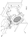
- FIG. 6 is another schematic perspective view of an illustrative gas valve, air/gas admittance device and fan assembly 10 for use with a combustion unit with an alternative pressure sensor connection.
- the assembly 10 may be substantially similar in form and function to the assembly 10 as described with respect to Figures 1-5 . It should be understood that like numbers represent like parts.
- pressure sensors may be positioned within a box 90 coupled to the valve body of the valve assembly 12.
- the pressure sensors may be fluidly coupled or operatively coupled to the pressure ports 20 via conduits or tubes 92a, 92b, 92c (collectively, 92).
- the pressure sensors may be in operative communication with a fluid (e.g.
- the pressure ports 20 may be operatively coupled to a pressure sensor.
- the remaining (e.g. without tubes 92) pressure ports 20 may be plugged or otherwise blocked.
- the pressure sensors may also be in operative communication (e.g., through a wired or wireless connection) to the valve controller 18.
- an illustrative air/gas admittance device for use with a combustion unit may comprise a body having a side wall defining a passageway that extends from an air inlet to an air/gas outlet and a gas pipe having a side wall defining a passageway that extends from a gas inlet to a gas outlet.
- the side wall of the body may have a gas pipe opening that is in fluid communication with the gas outlet of the gas pipe.
- An air flow restrictor may be positioned in the body between the gas pipe opening and the air inlet and a gas flow restrictor may be positioned in the gas pipe downstream of the gas inlet.
- a first pressure port may be in the side wall of the body, upstream of the gas pipe opening.
- the first pressure port may be configured to be operatively coupled to a first pressure sensor for measuring a pressure of air within the body.
- a second pressure port may be in the side wall of the gas pipe.
- the second pressure port may be configured to be operatively coupled to a second pressure sensor for measuring a pressure of gas within the gas pipe.
- An air flow smoothing insert may be positioned in the body upstream of the first pressure port.
- the air/gas admittance device may further comprise a third pressure port in the side wall of the body downstream of the gas pipe opening.
- the third pressure port may be configured to be operatively coupled to a third pressure sensor for measuring a pressure adjacent the air/gas outlet.
- the first pressure port may be positioned upstream of the air flow restrictor, and the second pressure port may be positioned upstream of the gas flow restrictor.
- the air/gas admittance device may further comprise an outlet flange mounted to the body adjacent to the air/gas outlet.
- the air/gas admittance device may further comprise a fan mounted to the outlet flange for creating an under pressure at the air/gas outlet of the body.
- the air/gas admittance device may further comprise a fourth pressure port in the side wall of the body, upstream of the gas pipe opening and opposing the first pressure port and a fifth pressure port in the side wall of the gas pipe and opposing the second pressure port.
- the air/gas admittance device may further comprise a sixth pressure port in the side wall of the body, downstream of the gas pipe opening and opposing the third pressure port.
- the air/gas admittance device may further comprise an air inlet flange coupled to the body adjacent to the air inlet.
- the air/gas admittance device may further comprise an air damper coupled to the air inlet flange.
- the air/gas admittance device may further comprise a gas inlet flange coupled to the gas pipe adjacent to the gas inlet.
- the air/gas admittance device may further comprise a gas valve coupled to the gas inlet flange.
- the air flow smoothing insert may be positioned upstream of the air flow restrictor.
- the air/gas admittance device may further comprise a gas flow smoothing insert positioned upstream of the second pressure port.
- an air/gas admittance device for use with a combustion unit may comprise a body having a side wall defining a passageway that extends from an air inlet to an air/gas outlet and a gas pipe having a side wall defining a passageway that extends from a gas inlet to a gas outlet.
- the side wall of the body may have a gas pipe opening that is in fluid communication with the gas outlet of the gas pipe.
- An air flow restrictor may be positioned in the body between the gas pipe opening and the air inlet and an air flow smoothing insert may be positioned in the body upstream of the gas pipe opening.
- the device may further comprise a fan in fluid communication with the air/gas outlet. The fan may be configured to generate an under pressure at the air/gas outlet.
- the air/gas admittance device may further comprise a first pressure port in the side wall of the body, upstream of the gas pipe opening.
- the first pressure port may be configured to be operatively coupled to a first pressure sensor for measuring a pressure of air within the body.
- the air/gas admittance device may further comprise a second pressure port in the side wall of the gas pipe.
- the second pressure port may be configured to be operatively coupled to a second pressure sensor for measuring a pressure of gas within the gas pipe.
- the air/gas admittance device may further comprise a third pressure port in the side wall of the body downstream of the gas pipe opening.
- the third pressure port may be configured to be operatively coupled to a third pressure sensor for measuring a pressure adjacent the air/gas outlet.
- the air/gas admittance device may further comprise an outlet flange mounted to the body adjacent to the air/gas outlet, and wherein the fan is mounted directly to the outlet flange.
- the air/gas admittance device may further comprise a gas inlet flange coupled to the gas pipe adjacent to the gas inlet and a gas valve mounted directly to the gas inlet flange.
- an air/gas admittance device for use with a combustion unit may comprise a body having a side wall defining a passageway that extends from an air inlet to an air/gas outlet and a gas pipe having a side wall defining a passageway that extends from a gas inlet to a gas outlet.
- the side wall of the body may have a gas pipe opening that is in fluid communication with the gas outlet of the gas pipe.
- a first pressure port may be in the side wall of the body, upstream of the gas pipe opening.
- a first pressure sensor may be operatively coupled to the first pressure port for measuring a pressure of air within the body.
- a second pressure port may be in the side wall of the gas pipe.
- a second pressure sensor may be operatively coupled to the second pressure port for measuring a pressure of gas within the gas pipe.
- An air flow smoothing insert may be positioned in the body upstream of the first pressure port.
- a gas control valve may be coupled to the gas inlet.
- a controller may be operatively coupled to the first pressure sensor, the second pressure sensor and the gas control valve. The controller may be configured to use the pressure of air within the body sensed by the first pressure sensor and the pressure of gas within the gas pipe sensed by the second pressure sensor to control the gas valve to produce a desired air/gas mixture at the air/gas outlet.
- the air/gas admittance device may further comprising a third pressure port in the side wall of the body downstream of the gas pipe opening and a third pressure sensor operatively coupled to the third pressure port for measuring a pressure adjacent the air/gas outlet.
- the controller may be configured to use the pressure of air within the body sensed by the first pressure sensor, the pressure of gas within the gas pipe sensed by the second pressure sensor, and the pressure adjacent the air/gas outlet sensed by the third pressure sensor to control the gas valve to produce a desired air/gas mixture at the air/gas outlet.
Landscapes
- Engineering & Computer Science (AREA)
- Chemical & Material Sciences (AREA)
- Combustion & Propulsion (AREA)
- Mechanical Engineering (AREA)
- General Engineering & Computer Science (AREA)
- Regulation And Control Of Combustion (AREA)
Abstract
Description
- The present disclosure relates generally to systems and methods for admitting air and fuel to a burner of a combustion appliance, and more particularly to a device and method for delivering an accurate air/fuel ratio to a burner of a combustion appliance.
- The air/fuel ratio used during the operation of a combustion appliance can affect the efficiency and emissions of the combustion appliance. Example combustion appliances include furnaces, water heaters, boilers, direct/in-direct make-up air heaters, power/jet burners and any other residential, commercial or industrial combustion appliance. In many cases, the flow of gas is adjusted to set the air/fuel ratio. This is often accomplished by modulating a gas valve to control the pressure and thus the flow of gas to the combustion appliance. In some cases, the gas valve is modulated based on signals from one or more pressure or flow sensors placed in the gas and/or air streams. In some cases, turbulent and/or otherwise non-uniform gas and/or air flows can introduce noise into the pressure or flow sensor signals, which can result in a non-uniform or otherwise non-optimal air/fuel ratio. This can reduce the efficiency and/or increase the emissions of the combustion appliance. What would be desirable is an improved air/gas admittance device that provides a more uniform gas and/or air flow to reduce sensor noise and thus improve the efficiency and/or emissions of a combustion appliance.
- The present disclosure relates generally to an improved air/gas admittance device that provides a more uniform gas and/or air flow to reduce sensor noise and thus improve the efficiency and/or emissions of a combustion appliance.
- In one example, an illustrative air/gas admittance device for use with a combustion unit such as a combustion appliance may include a body having a side wall defining a passageway that extends from an air inlet to an air/gas outlet and a gas pipe having a side wall defining a passageway that extends from a gas inlet to a gas outlet. The side wall of the body may have a gas pipe opening that is in fluid communication with the gas outlet of the gas pipe. An air flow restrictor may be positioned in the body between the gas pipe opening and the air inlet, and a gas flow restrictor may be positioned in the gas pipe downstream of the gas inlet. A first pressure port may be in the side wall of the body, upstream of the gas pipe opening. The first pressure port may be configured to be operatively coupled to a first pressure sensor for measuring a pressure of air within the body. A second pressure port may be in the side wall of the gas pipe. The second pressure port may be configured to be operatively coupled to a second pressure sensor for measuring a pressure of gas within the gas pipe. An air flow smoothing insert may be positioned in the body upstream of the first pressure port.
- In another example, an air/gas admittance device for use with a combustion unit may comprise a body having a side wall defining a passageway that extends from an air inlet to an air/gas outlet and a gas pipe having a side wall defining a passageway that extends from a gas inlet to a gas outlet. The side wall of the body may have a gas pipe opening that is in fluid communication with the gas outlet of the gas pipe. An air flow restrictor may be positioned in the body between the gas pipe opening and the air inlet and an air flow smoothing insert may be positioned in the body upstream of the gas pipe opening. The device may further comprise a fan in fluid communication with the air/gas outlet. The fan may be configured to generate an under pressure at the air/gas outlet.
- In another example, an air/gas admittance device for use with a combustion unit may comprise a body having a side wall defining a passageway that extends from an air inlet to an air/gas outlet and a gas pipe having a side wall defining a passageway that extends from a gas inlet to a gas outlet. The side wall of the body may have a gas pipe opening that is in fluid communication with the gas outlet of the gas pipe. A first pressure port may be in the side wall of the body, upstream of the gas pipe opening. A first pressure sensor may be operatively coupled to the first pressure port for measuring a pressure of air within the body. A second pressure port may be in the side wall of the gas pipe. A second pressure sensor may be operatively coupled to the second pressure port for measuring a pressure of gas within the gas pipe. An air flow smoothing insert may be positioned in the body upstream of the first pressure port. A gas control valve may be coupled to the gas inlet. A controller may be operatively coupled to the first pressure sensor, the second pressure sensor and the gas control valve. The controller may be configured to use the pressure of air within the body sensed by the first pressure sensor and the pressure of gas within the gas pipe sensed by the second pressure sensor to control the gas valve to produce a desired air/gas mixture at the air/gas outlet.
- The preceding summary is provided to facilitate an understanding of some of the innovative features unique to the present disclosure and is not intended to be a full description. A full appreciation of the disclosure can be gained by taking the entire specification, claims, drawings, and abstract as a whole.
- The disclosure may be more completely understood in consideration of the following description of various illustrative embodiments in connection with the accompanying drawings, in which:
-
Figure 1 is a schematic perspective view of an illustrative gas valve, air/gas admittance device and fan assembly for use with a combustion unit; -
Figure 2 is a schematic side view of the illustrative air/gas admittance device ofFigure 1 ; -
Figure 3 is a schematic top view of the illustrative air/gas admittance device ofFigure 1 ; -
Figure 4 is a cross-sectional view of the illustrative air/gas admittance device ofFigure 4 , taken along line 4-4; -
Figure 5 is a schematic block diagram of an illustrative valve controller for controlling the gas valve ofFigure 1 ; and -
Figure 6 is a schematic perspective view of another illustrative gas valve, air/gas admittance device and fan assembly for use with a combustion unit. - While the disclosure is amenable to various modifications and alternative forms, specifics thereof have been shown by way of example in the drawings and will be described in detail. It should be understood, however, that the intention is not to limit aspects of the disclosure to the particular illustrative embodiments described. On the contrary, the intention is to cover all modifications, equivalents, and alternatives falling within the spirit and scope of the disclosure.
- The following description should be read with reference to the drawings wherein like reference numerals indicate like elements throughout the several views. The description and drawings show several illustrative embodiments which are meant to be illustrative of the claimed disclosure.
- Gas valves are often driven by electronic control systems which evaluate feedback signals from pressure and/or flow sensors. When pressure sensors are used, the pressure sensors may relay pressure readings to a controller which controls a position of the gas valve. The position of the gas valve may be adjusted to optimize the air to fuel (A/F) ratio in order to achieve low emissions of CO, NOx and/or to increase efficiency (e.g. save fuel). The pressure sensors may be placed to sense pressures before and/or after air and gas restrictors in an air/gas admittance device. Ideally, signals from the pressure signals are stable and largely free of oscillations and/or other noise caused by air or gas flow disturbances in the admittance device. Unstable pressure sensor signals can result in a non-uniform or otherwise non-optimal air/fuel ratio, which can reduce the efficiency and/or increase the emissions of the combustion unit. The air/gas admittance device described herein provides a more uniform gas and/or air flow, which reduces sensor noise and can improve the efficiency and/or emissions of a downstream combustion unit.
-
Figure 1 is a schematic perspective view of an illustrative gas valve, air/gas admittance device and fan assembly for use with a combustion unit. Theillustrative assembly 10 includes agas valve assembly 12 for controlling gas flow to acombustion unit 17 or other similar or difference devices, an air/gas admittance device 14, a fan orblower 16, and avalve controller 18. While not explicitly shown, thegas valve assembly 12 may include a valve body that includes an inlet port coupled to a gas source 11, an outlet port configured to be coupled to a portion of the air/gas admittance device 14, and a fluid path or fluid channel extending between the inlet port and the outlet port. A valve member may control the flow of gas from the inlet port to the outlet port. Some illustrative gas valves are described in commonly assignedU.S. Patent Publication No. 2013/0153042 andU.S. Patent Publication No. 2013/0153041 , which are herein incorporated by reference. - The
gas valve assembly 12 may include one or more actuators to modulate the flow of gas that is provided to the air/gas admittance device 14. Thevalve controller 18 may control thegas valve assembly 12 based on signals from one or more pressure orflow sensors 22a-22c in order to provide a desired air/fuel ratio to the downstream fan orblower 16. In the example shown, the downstream fan orblower 16 mixes the air and gas streams and provides the mixed air/gas stream to a combustion chamber of thedownstream combustion unit 17. - In the example shown, the
gas valve assembly 12 is shown coupled to the air/gas admittance device 14. The air/gas admittance device 14 may be configured to provide air and gas (e.g. fuel) at a desired ratio to adownstream combustion unit 17. The illustrative air/gas admittance device 14 includes abody 26 having aside wall 78 defining apassageway 64 extending from anair inlet 50 to an air/gas outlet 62 (see, for example,Figure 4 ). In some cases, thebody 26 may have a generally tubular or cylindrical shape, although this is not required. Thebody 26 may include anair inlet flange 34 mounted adjacent to an air inlet, or first, end 30 thereof. Theair inlet flange 34 may include one ormore apertures 56 for receiving a fastening mechanism, including but not limited to bolts, screws, etc. Theair inlet flange 34 may be configured to be connected (e.g. viaapertures 56 and a fastening mechanism) to astructure 72 configured to control a flow of air, such as, but not limited to a valve, an air damper, or the like. For clarity, the airflow control structure 72 is shown uncoupled from theair inlet flange 34. A valve or damper can be closed to stop or prevent air flow when a combustion unit is not in use. In some cases, the valve ordamper 72 is not provided. - The
body 26 of the air/gas admittance device 14 may also include an air/gas outlet flange 36 mounted adjacent to an air/gas outlet, or second, end 32 thereof. The air/gas outlet flange 36 may include one ormore apertures 58 for receiving a fastening mechanism, including but not limited to a bolt, screw, etc. The air/gas outlet flange 36 may be configured to be connected (e.g. viaapertures 58 and a fastening mechanism) to the fan orblower 16. In some cases, the air/gas outlet flange 36 may be directly coupled to a housing of the fan orblower 16. As the fan and/orblower 16 turns, the fan orblower 16 may generate an under pressure at the air/gas outlet 62 and/or in thepassageway 64 of the air/gas admittance device 14, drawing air in through theair inlet 50 andgas inlet 68 and to the air/gas outlet 62, as will be described in more detail herein. - The air/
gas admittance device 14 may include agas pipe 28 extending generally orthogonal to thebody 26. Thegas pipe 28 may have aside wall 82 defining apassageway 66 extending from agas inlet 68 to a gas pipe outlet 70 (see, for example,Figure 4 ). In some cases, thegas pipe 28 may have a generally tubular or cylindrical shape, although this is not required. Thegas pipe 28 may include agas inlet flange 40 mounted adjacent to thegas inlet 68, or first, end 38 thereof. Thegas inlet flange 40 may be configured to be connected to the body of thegas valve assembly 12. Thegas inlet flange 40 may include one ormore apertures 55 for receiving a fastening mechanism, including but not limited to bolts, screws, etc. Thegas inlet flange 40 may be configured to be connected (e.g. viaapertures 55 and a fastening mechanism) to the housing of thegas valve assembly 12. In some cases, the flow of gas may be drawn into the air/gas admittance device 14 aided by an under pressure created by the fan orblower 16. - The air/
gas admittance device 14 may include a plurality of pressure ports formed in theside wall 78 of thebody 26 and/or theside wall 82 of thegas pipe 28. In the example shown, the pressure ports may include afirst pressure port 20a, asecond pressure port 20b, and athird pressure port 20c (collectively, 20) extending through theside walls passageways sensor passageways valve controller 18. The pressure sensors 22 may provide pressure readings to thevalve controller 18, which in turn may adjust a flow of gas from thegas valve assembly 12 to achieve a desired air/fuel ratio. More specifically, in order to achieve low emissions of CO, NOx and/or to increase efficiency (e.g. save fuel), thegas valve assembly 12 may be operated to control the air/fuel ratio (e.g. Lamba) of the mixed air stream provided to thecombustion unit 17. In some applications, Lambda may be a function of the pressure amplification ratio. The pressure readings may be used to determine a pressure amplification ratio defined by the following equation:
pressure sensor 22b), Pair is a pressure of the air (e.g. obtained atpressure sensor 22a), and PRef is a reference pressure of an air/gas mixture (e.g. obtained atpressure sensor 22c). In order to maintain lambda (e.g. air/fuel ratio) at a desired (e.g. relatively constant) value, it is desirable to maintain the pressure amplification ratio (Pamp) at a constant value. In the example shown, thevalve controller 18 may obtain pressure readings from the three pressure sensors (e.g. 22a, 22b, 22c) and determine a Pamp value. Thevalve controller 18 may then adjust a position of the gas valve assembly 12 (and hence adjust a flow of gas to thegas inlet 68 of the air/gas admittance device 14) to maintain the Pamp value essentially constant. For best performance and control, it is desirable for the pressure readings to be stable and free from oscillations and/or other noise caused by turbulent and/or non-uniform air and/or gas flows. - In some cases, an air
flow smoothing insert 42 may be positioned within thepassageway 64 of thebody 26. Alternatively, or additionally, a gas flow smoothing insert (not shown), similar in form and function to the airflow smoothing insert 42 may be positioned within thepassage way 82 of thegas pipe 28. The airflow smoothing insert 42 may be configured to filter and reduce or eliminate flow disturbances from the air entering the air/gas admittance device 14. This may result in a more stable flow uniformly spread over thewhole air passageways 64. As a result, the pressure readings obtained at the pressure sensors 22 may be more stable and largely free from oscillations and/or other noise in a compact simple assembly. - The air
flow smoothing insert 42 may include a plurality ofopenings 44 separated by a plurality ofwalls 45. In some cases, a portion of theopenings 44 may have a generally hexagonal cross-sectional shape. In other words, the airflow smoothing insert 42 may have a generally honeycomb type configuration. However, it is contemplated that theopenings 44 may have any cross-sectional shape desired, including, but not limited to, circular, oblong, square, rectangular, polygonal, etc. -
Figure 2 is a side view of the illustrative air/gas admittance device 14 ofFigure 1 . The air/gas admittance device 14 may include at least one slot orchannel 48a in formed in theside wall 78 of thebody 26. Thechannel 48a may be configured to slidably receive aportion 52a of the airflow smoothing insert 42. This may allow the airflow smoothing insert 42 to be removably positioned with thepassageway 64 on an as-needed basis. In some cases, asecond slot 48b may be provided opposite from thefirst slot 48a, as shown inFigure 4 . Additional slots may be provided as desired. - The
body 26 of the air/gas admittance device 14 may include two (or more)additional pressure ports side wall 78 of thebody 26. Thepressure ports pressure ports Figure 1 , although thepressure ports pressure ports gas admittance device 14 may be used in an application (e.g. pressure ports pressure ports additional pressure ports gas admittance device 14 to facilitate installation that block access topressure ports 20a-20c. For example, the installer may utilize the pressure ports 20 that are easiest to access. The pressure ports 20 that do not receive a pressure sensor 22 may be blocked or plugged with aplug screw - In the example show, a
gas flow restrictor 46 may be positioned within thepassageway 66 of thegas pipe 28. Thegas flow restrictor 46 may have a reduce diameter DG relative to thepassageway 66. The diameter DG of thegas flow restrictor 46 may be precisely controlled to provide a predictable and consistent flow of gas into thebody 26 of the air/gas admittance device 14 to aid in providing a constant and/or precise air/fuel ratio to the combustion unit. In some cases, thegas flow restrictor 46 may be removably positioned within thepassageway 66. This may allow the gas flow restrictor 46 to be changed to accommodate different burner loads and/or different air/gas ratios. That is, different diameter DGgas flow restrictors 46 may be used in differing applications or configurations to provide a desired flow of gas to achieve a desired air/fuel ratio for a givencombustion unit 17. -
Figure 3 is a top view of the illustrative air/gas admittance device 14 ofFigure 1 . As can be seen, the illustrative airflow smoothing insert 42 may include one or more regions orportions flow smoothing insert 42. Theseportions corresponding channels side wall 78 of thebody 26. While not explicitly shown, thegas pipe 28 may similarly include slots or channels configured to receive a gas flow smoothing insert similar in form and function to the airflow smoothing insert 42, but this is not required. - The
gas pipe 28 of the air/gas admittance device 14 may include anadditional pressure ports 20e formed in theside wall 82 of thegas pipe 28. Thepressure port 20e may be positioned generally opposite from or 180° from (e.g. opposing) thepressure port 20b shown inFigure 1 , although thepressure port 20e, can be oriented in any manner desired. Thepressure port 20e may be configured to receive or be operatively coupled to a pressure sensor (not explicitly shown). It is contemplated that only the pressure ports 20 on one side of the air/gas admittance device 14 may be used in an application (e.g. pressure port 20b orpressure port 20e). Theadditional pressure port 20e may be provided in the air/gas admittance device 14 to facilitate installation. For example, the installer may utilize the pressure ports 20 that are easiest to access. The pressure ports 20 that do not receive a pressure sensor 22 may be blocked or plugged with aplug screw 54e or other removable mechanism. It is contemplated that only some of the pressure ports 20 will receive a pressure sensor 22. For example, only one of theair pressure ports gas pressure ports pressure ports plug screw 54 or the like. -
Figure 4 is a cross-section of the illustrative air/gas admittance device 14 taken at line 4-4 ofFigure 3 . In the example shown, anair flow restrictor 60 may be positioned within theair passageway 64 of thebody 26. Theair flow restrictor 60 may have a reduce diameter DA relative to theair passageway 64. The diameter DA of theair flow restrictor 60 and the diameter DG of thegas flow restrictor 46 may be precisely controlled to help provide a predictable and consistent air/fuel ratio to thecombustion unit 17. In some cases, theair flow restrictor 60 may be removably positioned within thepassageway 64. This may allow the air flow restrictor 60 to be easily changed to accommodate different combustion units. In other words, different diameter DAair flow restrictors 60 and/or different diameter DGgas flow restrictors 46 may be used in differing applications or configurations to provide a controlled air/fuel volumetric rate and air/fuel ratio to support a givencombustion unit 17. - The
body 26 of the air/gas admittance device 14 may include anopening 80 extending through theside wall 78 thereof. Theopening 80 may be downstream of theair flow restrictor 60 and upstream of thereference pressure port second end 76 of thegas pipe 28 may be secured to theside wall 78 of thebody 26 such that the gas pipe outlet 70 (and passageway 66) is in fluid communication with theopening 80 and thepassageway 64 of thebody 26. - The
gas flow restrictor 46 may be positioned with the gas pipe 28 (e.g. within the passageway 66) downstream of thegas inlet 68 and upstream thegas pipe outlet 70. In the example shown, thegas flow restrictor 46 may also be positioned downstream of thegas pressure port gas flow restrictor 46 and prior to the gas mixing with air. - The
air flow restrictor 60 may be positioned downstream of theair inlet 50 and upstream of the opening 80 (and/or gas pipe outlet 70) in theside wall 78. In the example shown, theair pressure port flow smoothing insert 42 and the air flow restrictor 60 to obtain an air pressure reading upstream of theair flow restrictor 60 and prior to mixing with gas. As such, theair pressure port air flow restrictor 60 and upstream of the opening 80 (and/or gas pipe outlet 70) in theside wall 78. - As shown in
Figure 4 , the airflow smoothing insert 42 may be positioned upstream of theair flow restrictor 60 and theair pressure port air flow restrictor 60. While the airflow smoothing insert 42 is illustrated as generally adjacent to theair inlet 50, the airflow smoothing insert 42 may be positioned at any location between theair inlet 50 and theair pressure ports gas flow restrictor 46 and thegas pressure port gas flow restrictor 46. A gas flow smoothing insert may be positioned at any location between thegas inlet 68 and thegas pressure ports - The
reference pressure port 20c and opposingreference pressure port 20f, it is contemplated that these pressure ports may be positioned between the opening 80 (and/or gas pipe outlet 70) and the air/gas ormixed outlet 62 of thebody 26 to obtain a pressure reading of the mixed gas and air. In other words, thereference pressure ports gas pipe outlet 70. While the air and gas are referred to as mixed within the downstream portion of the air/gas admittance device 14, it should be noted that the gas and air may not be completely mixed. Further mixing of the air and gas may occur in downstream components, such as, but not limited to the fan orblower 16. -
Figure 5 is a schematic block diagram of anillustrative valve controller 18 that may be used with thepresent assembly 10. Theillustrative valve controller 18 includes a processor orcontroller 100. Thevalve controller 18 may be adapted or configured to operate in accordance with an algorithm that controls or at least partially controls portions of thegas valve assembly 12. Thevalve controller 18 may include amemory block 102 that may be considered as being electrically connected to theprocessor 100. Thememory block 102 may be used to store any desired information, such as the aforementioned control algorithm, set points, A/F ratio versus burner load curves, and the like. Theprocessor 100 may store information withinmemory block 102 and may subsequently retrieved the stored information. Thememory block 102 may be any suitable type of storage device, such as RAM, ROM, EPROM, a flash drive, a hard drive, and the like. - In many cases, the
valve controller 18 may include an input/output block (I/O block) 104 having a number of wire terminals for receiving one or more wires from thegas valve assembly 12, thepressure sensors 22a-22c of the air/gas admittance device 14, and/or thecombustion unit 17. While the term I/O may imply both input and output, it is intended to include input only, output only, as well as both input and output. The I/O block 104 may be used to communicate one or more signals to and/or from thegas valve assembly 12, air/gas admittance device 14, and/or combustion unit. Thevalve controller 18 may have any number of wire terminals for accepting connections from thegas valve assembly 12, air/gas admittance device 14, and/orcombustion unit 17. How many and which of the wire terminals are actually used at a particular installation may depend on the particular configuration of thegas valve assembly 12, air/gas admittance device 14 and/orcombustion unit 17. - In some cases, as illustrated, the
valve controller 18 may include a communications ordata port 106. Thecommunication ports 106 may be configured to communicate with theprocessor 100 and may, if desired, be used to either upload information to theprocessor 100, download information from theprocessor 100, provide commands to theprocessor 100, send commands from theprocessor 100, and/or perform any other suitable task. Thecommunication port 106 may be a wireless port such as a Bluetooth™ port or any other wireless protocol. In some cases,communication port 106 may be a wired port such as a serial port, a parallel port, a CAT5 port, a USB (universal serial bus) port, or the like. In some instances, thecommunication port 106 may be a USB port and may be used to download and/or upload information from a USB flash drive. Other storage devices may also be employed, as desired. In some cases, a separate device may be in communication with theprocessor 100 of thevalve controller 18. - As noted above, the
valve controller 18 may be in wired or wireless communication with an external device. The external device may be a computing device separate from thegas valve assembly 12. For example, the external device may be a personal computer, tablet computer, smart phone, laptop computer, a server, or other computer as desired. In some cases, the external device may not be a part of thegas valve assembly 12 orcombustion unit 17. For example, the external device may be a portable device which travels with an installer. -
Figure 6 is another schematic perspective view of an illustrative gas valve, air/gas admittance device andfan assembly 10 for use with a combustion unit with an alternative pressure sensor connection. Theassembly 10 may be substantially similar in form and function to theassembly 10 as described with respect toFigures 1-5 . It should be understood that like numbers represent like parts. In the example shown inFigure 6 , pressure sensors may be positioned within abox 90 coupled to the valve body of thevalve assembly 12. The pressure sensors may be fluidly coupled or operatively coupled to the pressure ports 20 via conduits ortubes passageways valve controller 18. - In a first example, an illustrative air/gas admittance device for use with a combustion unit may comprise a body having a side wall defining a passageway that extends from an air inlet to an air/gas outlet and a gas pipe having a side wall defining a passageway that extends from a gas inlet to a gas outlet. The side wall of the body may have a gas pipe opening that is in fluid communication with the gas outlet of the gas pipe. An air flow restrictor may be positioned in the body between the gas pipe opening and the air inlet and a gas flow restrictor may be positioned in the gas pipe downstream of the gas inlet. A first pressure port may be in the side wall of the body, upstream of the gas pipe opening. The first pressure port may be configured to be operatively coupled to a first pressure sensor for measuring a pressure of air within the body. A second pressure port may be in the side wall of the gas pipe. The second pressure port may be configured to be operatively coupled to a second pressure sensor for measuring a pressure of gas within the gas pipe. An air flow smoothing insert may be positioned in the body upstream of the first pressure port.
- Alternatively or additionally to any of the examples above, in another example, the air/gas admittance device may further comprise a third pressure port in the side wall of the body downstream of the gas pipe opening. The third pressure port may be configured to be operatively coupled to a third pressure sensor for measuring a pressure adjacent the air/gas outlet.
- Alternatively or additionally to any of the examples above, in another example, the first pressure port may be positioned upstream of the air flow restrictor, and the second pressure port may be positioned upstream of the gas flow restrictor.
- Alternatively or additionally to any of the examples above, in another example, the air/gas admittance device may further comprise an outlet flange mounted to the body adjacent to the air/gas outlet.
- Alternatively or additionally to any of the examples above, in another example, the air/gas admittance device may further comprise a fan mounted to the outlet flange for creating an under pressure at the air/gas outlet of the body.
- Alternatively or additionally to any of the examples above, in another example, the air/gas admittance device may further comprise a fourth pressure port in the side wall of the body, upstream of the gas pipe opening and opposing the first pressure port and a fifth pressure port in the side wall of the gas pipe and opposing the second pressure port.
- Alternatively or additionally to any of the examples above, in another example, the air/gas admittance device may further comprise a sixth pressure port in the side wall of the body, downstream of the gas pipe opening and opposing the third pressure port.
- Alternatively or additionally to any of the examples above, in another example, the air/gas admittance device may further comprise an air inlet flange coupled to the body adjacent to the air inlet.
- Alternatively or additionally to any of the examples above, in another example, the air/gas admittance device may further comprise an air damper coupled to the air inlet flange.
- Alternatively or additionally to any of the examples above, in another example, the air/gas admittance device may further comprise a gas inlet flange coupled to the gas pipe adjacent to the gas inlet.
- Alternatively or additionally to any of the examples above, in another example, the air/gas admittance device may further comprise a gas valve coupled to the gas inlet flange.
- Alternatively or additionally to any of the examples above, in another example, the air flow smoothing insert may be positioned upstream of the air flow restrictor.
- Alternatively or additionally to any of the examples above, in another example, the air/gas admittance device may further comprise a gas flow smoothing insert positioned upstream of the second pressure port.
- In another example, an air/gas admittance device for use with a combustion unit may comprise a body having a side wall defining a passageway that extends from an air inlet to an air/gas outlet and a gas pipe having a side wall defining a passageway that extends from a gas inlet to a gas outlet. The side wall of the body may have a gas pipe opening that is in fluid communication with the gas outlet of the gas pipe. An air flow restrictor may be positioned in the body between the gas pipe opening and the air inlet and an air flow smoothing insert may be positioned in the body upstream of the gas pipe opening. The device may further comprise a fan in fluid communication with the air/gas outlet. The fan may be configured to generate an under pressure at the air/gas outlet.
- Alternatively or additionally to any of the examples above, in another example, the air/gas admittance device may further comprise a first pressure port in the side wall of the body, upstream of the gas pipe opening. The first pressure port may be configured to be operatively coupled to a first pressure sensor for measuring a pressure of air within the body. The air/gas admittance device may further comprise a second pressure port in the side wall of the gas pipe. The second pressure port may be configured to be operatively coupled to a second pressure sensor for measuring a pressure of gas within the gas pipe.
- Alternatively or additionally to any of the examples above, in another example, the air/gas admittance device may further comprise a third pressure port in the side wall of the body downstream of the gas pipe opening. The third pressure port may be configured to be operatively coupled to a third pressure sensor for measuring a pressure adjacent the air/gas outlet.
- Alternatively or additionally to any of the examples above, in another example, the air/gas admittance device may further comprise an outlet flange mounted to the body adjacent to the air/gas outlet, and wherein the fan is mounted directly to the outlet flange.
- Alternatively or additionally to any of the examples above, in another example, the air/gas admittance device may further comprise a gas inlet flange coupled to the gas pipe adjacent to the gas inlet and a gas valve mounted directly to the gas inlet flange.
- In another example, an air/gas admittance device for use with a combustion unit may comprise a body having a side wall defining a passageway that extends from an air inlet to an air/gas outlet and a gas pipe having a side wall defining a passageway that extends from a gas inlet to a gas outlet. The side wall of the body may have a gas pipe opening that is in fluid communication with the gas outlet of the gas pipe. A first pressure port may be in the side wall of the body, upstream of the gas pipe opening. A first pressure sensor may be operatively coupled to the first pressure port for measuring a pressure of air within the body. A second pressure port may be in the side wall of the gas pipe. A second pressure sensor may be operatively coupled to the second pressure port for measuring a pressure of gas within the gas pipe. An air flow smoothing insert may be positioned in the body upstream of the first pressure port. A gas control valve may be coupled to the gas inlet. A controller may be operatively coupled to the first pressure sensor, the second pressure sensor and the gas control valve. The controller may be configured to use the pressure of air within the body sensed by the first pressure sensor and the pressure of gas within the gas pipe sensed by the second pressure sensor to control the gas valve to produce a desired air/gas mixture at the air/gas outlet.
- Alternatively or additionally to any of the examples above, in another example, the air/gas admittance device may further comprising a third pressure port in the side wall of the body downstream of the gas pipe opening and a third pressure sensor operatively coupled to the third pressure port for measuring a pressure adjacent the air/gas outlet. The controller may be configured to use the pressure of air within the body sensed by the first pressure sensor, the pressure of gas within the gas pipe sensed by the second pressure sensor, and the pressure adjacent the air/gas outlet sensed by the third pressure sensor to control the gas valve to produce a desired air/gas mixture at the air/gas outlet.
- It should be understood that this disclosure is, in many respects, only illustrative. The various individual elements discussed above may be arranged or configured in any combination thereof without exceeding the scope of the disclosure. Changes may be made in details, particularly in matters of shape, size, and arrangement of steps without exceeding the scope of the disclosure. The disclosure's scope is, of course, defined in the language in which the appended claims are expressed.
- Preferred Embodiments of the Present Invention are as Numbered Below:
- 1. An air/gas admittance device for use with a combustion unit, the air/gas admittance device comprising:
- a body having a side wall defining a passageway that extends from an air inlet to an air/gas outlet;
- a gas pipe having a side wall defining a passageway that extends from a gas inlet to a gas outlet;
- the side wall of the body having a gas pipe opening that is in fluid communication with the gas outlet of the gas pipe;
- an air flow restrictor positioned in the body between the gas pipe opening and the air inlet;
- a gas flow restrictor positioned in the gas pipe downstream of the gas inlet;
- a first pressure port in the side wall of the body, upstream of the gas pipe opening, the first pressure port configured to be operatively coupled to a first pressure sensor for measuring a pressure of air within the body;
- a second pressure port in the side wall of the gas pipe, the second pressure port configured to be operatively coupled to a second pressure sensor for measuring a pressure of gas within the gas pipe; and
- an air flow smoothing insert positioned in the body upstream of the first pressure port.
- 2. The air/gas admittance device of 1, further comprising a third pressure port in the side wall of the body downstream of the gas pipe opening, the third pressure port configured to be operatively coupled to a third pressure sensor for measuring a pressure adjacent the air/gas outlet.
- 3. The air/gas admittance device of 1, wherein the first pressure port is positioned upstream of the air flow restrictor, and the second pressure port is positioned upstream of the gas flow restrictor.
- 4. The air/gas admittance device of 1, further comprising an outlet flange mounted to the body adjacent to the air/gas outlet.
- 5. The air/gas admittance device of 4, further comprising a fan mounted to the outlet flange for creating an under pressure at the air/gas outlet of the body.
- 6. The air/gas admittance device of 2, further comprising:
- a fourth pressure port in the side wall of the body, upstream of the gas pipe opening and opposing the first pressure port; and
- a fifth pressure port in the side wall of the gas pipe and opposing the second pressure port.
- 7. The air/gas admittance device of 6, further comprising a sixth pressure port in the side wall of the body, downstream of the gas pipe opening and opposing the third pressure port.
- 8. The air/gas admittance device of 1, further comprising an air inlet flange coupled to the body adjacent to the air inlet.
- 9. The air/gas admittance device of 8, further comprising an air damper coupled to the air inlet flange.
- 10. The air/gas admittance device of 1, further comprising a gas inlet flange coupled to the gas pipe adjacent to the gas inlet.
- 11. The air/gas admittance device of 10, further comprising a gas valve coupled to the gas inlet flange.
- 12. The air/gas admittance device of 1, wherein the air flow smoothing insert is positioned upstream of the air flow restrictor.
- 13. The air/gas admittance device of 1, further comprising a gas flow smoothing insert positioned upstream of the second pressure port.
- 14. An air/gas admittance device for use with a combustion unit, the air/gas admittance device comprising:
- a body having a side wall defining a passageway that extends from an air inlet to an air/gas outlet;
- a gas pipe having a side wall defining a passageway that extends from a gas inlet to a gas outlet;
- the side wall of the body having a gas pipe opening that is in fluid communication with the gas outlet of the gas pipe;
- an air flow restrictor positioned in the body between the gas pipe opening and the air inlet;
- an air flow smoothing insert positioned in the body upstream of the gas pipe opening; and
- a fan in fluid communication with the air/gas outlet, the fan configured to generate an under pressure at the air/gas outlet.
- 15. The air/gas admittance device of 14, further comprising:
- a first pressure port in the side wall of the body, upstream of the gas pipe opening, the first pressure port configured to be operatively coupled to a first pressure sensor for measuring a pressure of air within the body; and
- a second pressure port in the side wall of the gas pipe, the second pressure port configured to be operatively coupled to a second pressure sensor for measuring a pressure of gas within the gas pipe.
- 16. The air/gas admittance device of 15, further comprising a third pressure port in the side wall of the body downstream of the gas pipe opening, the third pressure port configured to be operatively coupled to a third pressure sensor for measuring a pressure adjacent the air/gas outlet.
- 17. The air/gas admittance device of 14, further comprising an outlet flange mounted to the body adjacent to the air/gas outlet, and wherein the fan is mounted directly to the outlet flange.
- 18. The air/gas admittance device of 14, further comprising:
- a gas inlet flange coupled to the gas pipe adjacent to the gas inlet; and
- a gas valve mounted directly to the gas inlet flange.
- 19. An air/gas admittance device for use with a combustion unit, the air/gas admittance device comprising:
- a body having a side wall defining a passageway that extends from an air inlet to an air/gas outlet;
- a gas pipe having a side wall defining a passageway that extends from a gas inlet to a gas outlet;
- the side wall of the body having a gas pipe opening that is in fluid communication with the gas outlet of the gas pipe;
- a first pressure port in the side wall of the body, upstream of the gas pipe opening;
- a first pressure sensor operatively coupled to the first pressure port for measuring a pressure of air within the body;
- a second pressure port in the side wall of the gas pipe;
- a second pressure sensor operatively coupled to the second pressure port for measuring a pressure of gas within the gas pipe;
- an air flow smoothing insert positioned in the body upstream of the first pressure port;
- a gas control valve coupled to the gas inlet; and
- a controller operatively coupled to the first pressure sensor, the second pressure sensor and the gas control valve, the controller is configured to use the pressure of air within the body sensed by the first pressure sensor and the pressure of gas within the gas pipe sensed by the second pressure sensor to control the gas valve to produce a desired air/gas mixture at the air/gas outlet.
- 20. The air/gas admittance device of 19, further comprising:
- a third pressure port in the side wall of the body downstream of the gas pipe opening;
- a third pressure sensor operatively coupled to the third pressure port for measuring a pressure adjacent the air/gas outlet; and
- wherein the controller is configured to use the pressure of air within the body sensed by the first pressure sensor, the pressure of gas within the gas pipe sensed by the second pressure sensor, and the pressure adjacent the air/gas outlet sensed by the third pressure sensor to control the gas valve to produce a desired air/gas mixture at the air/gas outlet.
Claims (15)
- An air/gas admittance device for use with a combustion unit, the air/gas admittance device comprising:a body having a side wall defining a passageway that extends from an air inlet to an air/gas outlet;a gas pipe having a side wall defining a passageway that extends from a gas inlet to a gas outlet;the side wall of the body having a gas pipe opening that is in fluid communication with the gas outlet of the gas pipe;an air flow restrictor positioned in the body between the gas pipe opening and the air inlet;a gas flow restrictor positioned in the gas pipe downstream of the gas inlet;a first pressure port in the side wall of the body, upstream of the gas pipe opening, the first pressure port configured to be operatively coupled to a first pressure sensor for measuring a pressure of air within the body;a second pressure port in the side wall of the gas pipe, the second pressure port configured to be operatively coupled to a second pressure sensor for measuring a pressure of gas within the gas pipe; andan air flow smoothing insert positioned in the body upstream of the first pressure port.
- The air/gas admittance device of claim 1, further comprising a third pressure port in the side wall of the body downstream of the gas pipe opening, the third pressure port configured to be operatively coupled to a third pressure sensor for measuring a pressure adjacent the air/gas outlet.
- The air/gas admittance device of any one of claims 1-2, wherein the first pressure port is positioned upstream of the air flow restrictor, and the second pressure port is positioned upstream of the gas flow restrictor.
- The air/gas admittance device of any one of claims 1-3, further comprising an outlet flange mounted to the body adjacent to the air/gas outlet.
- The air/gas admittance device of claim 4, further comprising a fan mounted to the outlet flange for creating an under pressure at the air/gas outlet of the body.
- The air/gas admittance device of any one of claims 2-5, further comprising:a fourth pressure port in the side wall of the body, upstream of the gas pipe opening and opposing the first pressure port; anda fifth pressure port in the side wall of the gas pipe and opposing the second pressure port.
- The air/gas admittance device of claim 6, further comprising a sixth pressure port in the side wall of the body, downstream of the gas pipe opening and opposing the third pressure port.
- The air/gas admittance device of any one of claims 1-7, further comprising an air inlet flange coupled to the body adjacent to the air inlet.
- The air/gas admittance device of claim 8, further comprising an air damper coupled to the air inlet flange.
- The air/gas admittance device of any one of claim 1-9, further comprising a gas inlet flange coupled to the gas pipe adjacent to the gas inlet.
- The air/gas admittance device of claim 10, further comprising a gas valve coupled to the gas inlet flange.
- The air/gas admittance device of any one of claims 1-11, wherein the air flow smoothing insert is positioned upstream of the air flow restrictor.
- The air/gas admittance device of any one of claims 1-12, further comprising a gas flow smoothing insert positioned upstream of the second pressure port.
- An air/gas admittance device for use with a combustion unit, the air/gas admittance device comprising:a body having a side wall defining a passageway that extends from an air inlet to an air/gas outlet;a gas pipe having a side wall defining a passageway that extends from a gas inlet to a gas outlet;the side wall of the body having a gas pipe opening that is in fluid communication with the gas outlet of the gas pipe;a first pressure port in the side wall of the body, upstream of the gas pipe opening;a first pressure sensor operatively coupled to the first pressure port for measuring a pressure of air within the body;a second pressure port in the side wall of the gas pipe;a second pressure sensor operatively coupled to the second pressure port for measuring a pressure of gas within the gas pipe;an air flow smoothing insert positioned in the body upstream of the first pressure port;a gas control valve coupled to the gas inlet; anda controller operatively coupled to the first pressure sensor, the second pressure sensor and the gas control valve, the controller is configured to use the pressure of air within the body sensed by the first pressure sensor and the pressure of gas within the gas pipe sensed by the second pressure sensor to control the gas valve to produce a desired air/gas mixture at the air/gas outlet.
- The air/gas admittance device of claim 14, further comprising:a third pressure port in the side wall of the body downstream of the gas pipe opening;a third pressure sensor operatively coupled to the third pressure port for measuring a pressure adjacent the air/gas outlet; andwherein the controller is configured to use the pressure of air within the body sensed by the first pressure sensor, the pressure of gas within the gas pipe sensed by the second pressure sensor, and the pressure adjacent the air/gas outlet sensed by the third pressure sensor to control the gas valve to produce a desired air/gas mixture at the air/gas outlet.
Applications Claiming Priority (1)
| Application Number | Priority Date | Filing Date | Title |
|---|---|---|---|
| US15/253,112 US10274195B2 (en) | 2016-08-31 | 2016-08-31 | Air/gas admittance device for a combustion appliance |
Publications (2)
| Publication Number | Publication Date |
|---|---|
| EP3290799A1 true EP3290799A1 (en) | 2018-03-07 |
| EP3290799B1 EP3290799B1 (en) | 2019-03-20 |
Family
ID=59558271
Family Applications (1)
| Application Number | Title | Priority Date | Filing Date |
|---|---|---|---|
| EP17184899.7A Active EP3290799B1 (en) | 2016-08-31 | 2017-08-04 | Air/gas admittance device for a combustion appliance |
Country Status (2)
| Country | Link |
|---|---|
| US (1) | US10274195B2 (en) |
| EP (1) | EP3290799B1 (en) |
Cited By (1)
| Publication number | Priority date | Publication date | Assignee | Title |
|---|---|---|---|---|
| EP4102134A1 (en) | 2021-06-11 | 2022-12-14 | BDR Thermea Group B.V. | Method for controlling the operation of a gas boiler |
Citations (5)
| Publication number | Priority date | Publication date | Assignee | Title |
|---|---|---|---|---|
| DD285155A5 (en) * | 1989-06-26 | 1990-12-05 | Veb Kombinat Ilka Luft- Und Kaeltetechnik,Dd | STROEMUNGSGLEICHRICHTER |
| DE102008041145A1 (en) * | 2008-08-11 | 2010-02-18 | Robert Bosch Gmbh | Sensor arrangement for determining a parameter of a fluid medium |
| EP2466202A2 (en) * | 2010-12-20 | 2012-06-20 | Vaillant GmbH | Method for regulating a gas/air mixture |
| US20130153042A1 (en) | 2011-12-15 | 2013-06-20 | Honeywell International Inc. | Gas valve with high/low gas pressure detection |
| US20130153041A1 (en) | 2011-12-15 | 2013-06-20 | Honeywell International Inc. | Gas valve with overpressure diagnostics |
Family Cites Families (59)
| Publication number | Priority date | Publication date | Assignee | Title |
|---|---|---|---|---|
| US2440329A (en) * | 1944-10-21 | 1948-04-27 | Stanley Steam Motors Corp | Control means for correlating supply of aspirating to aspirated fluids |
| US2648499A (en) * | 1951-01-25 | 1953-08-11 | Standard Oil Dev Co | Variable oil-gas fuel control system |
| US3299940A (en) * | 1963-06-22 | 1967-01-24 | American Smelting Refining | Burner structure |
| US3741710A (en) * | 1971-12-20 | 1973-06-26 | L Nelson | Combustion control valve means and system |
| JPS6018887B2 (en) * | 1978-04-17 | 1985-05-13 | 松下電器産業株式会社 | Combustion control device |
| JPS58224227A (en) * | 1982-06-21 | 1983-12-26 | Matsushita Electric Ind Co Ltd | Combustion control device |
| JPS59212622A (en) * | 1983-05-18 | 1984-12-01 | Matsushita Electric Ind Co Ltd | gas combustion control device |
| CH676497A5 (en) * | 1987-10-19 | 1991-01-31 | Landis & Gyr Betriebs Ag | Forced-draught gas-burner control - uses conduit pressure to regulate gas quantity |
| CH678099A5 (en) * | 1988-11-17 | 1991-07-31 | Basten Maria Sibylle | |
| WO1991006809A1 (en) * | 1989-10-30 | 1991-05-16 | Honeywell Inc. | Microbridge-based combustion control |
| JPH0776612B2 (en) * | 1990-07-03 | 1995-08-16 | 三浦工業株式会社 | Proportional combustion controller for gas fired boiler system |
| CA2099894C (en) * | 1992-07-10 | 1998-11-03 | Wayne C. Gensler | Apparatus and method for mixing gases |
| EP0644377B1 (en) * | 1993-09-16 | 1996-10-23 | Honeywell B.V. | Control device for gas burners |
| GB2327750A (en) * | 1997-07-28 | 1999-02-03 | Autoflame Eng Ltd | Burner control installation |
| JPH11183376A (en) * | 1997-12-19 | 1999-07-09 | Shimadzu Corp | Atomic absorption photometer |
| US5980835A (en) | 1998-01-02 | 1999-11-09 | Innovative Engineering Solutions, Inc. | Ambient air inlet assembly for a hazardous gas mixing apparatus |
| FR2775782B1 (en) * | 1998-03-06 | 2000-05-05 | Theobald Sa A | DIFFERENTIAL PRESSURE MEASURING DEVICE AND DEVICE FOR ACTIVE REGULATION OF THE AIR / GAS RATIO OF A BURNER USING SUCH A MEASURING DEVICE |
| DE19824521B4 (en) * | 1998-06-02 | 2004-12-23 | Honeywell B.V. | Control device for gas burners |
| US6322247B1 (en) | 1999-01-28 | 2001-11-27 | Honeywell International Inc. | Microsensor housing |
| US6135063A (en) * | 1999-03-11 | 2000-10-24 | Welden; David P. | Dual regulator direct-fired steam generator |
| DE19922226C1 (en) * | 1999-05-14 | 2000-11-30 | Honeywell Bv | Control device for gas burners |
| US6655207B1 (en) | 2000-02-16 | 2003-12-02 | Honeywell International Inc. | Flow rate module and integrated flow restrictor |
| US6537060B2 (en) * | 2001-03-09 | 2003-03-25 | Honeywell International Inc. | Regulating system for gas burners |
| CN1228568C (en) * | 2001-03-23 | 2005-11-23 | 多孔燃烧器技术销售有限责任公司 | Method and apparatus for setting air ratio |
| EP1323966A1 (en) * | 2001-12-21 | 2003-07-02 | G. Kromschröder Aktiengesellschaft | Device and method for controlling and cutting off a fluid flow |
| US7101172B2 (en) * | 2002-08-30 | 2006-09-05 | Emerson Electric Co. | Apparatus and methods for variable furnace control |
| US7048536B2 (en) * | 2003-04-25 | 2006-05-23 | Alzeta Corporation | Temperature-compensated combustion control |
| US6984122B2 (en) * | 2003-04-25 | 2006-01-10 | Alzeta Corporation | Combustion control with temperature compensation |
| DE10340045A1 (en) * | 2003-08-28 | 2005-03-24 | Karl Dungs Gmbh & Co. Kg | Ratio controller with dynamic ratio formation |
| DE102004055716C5 (en) * | 2004-06-23 | 2010-02-11 | Ebm-Papst Landshut Gmbh | Method for controlling a firing device and firing device (electronic composite I) |
| EP1761728B1 (en) * | 2004-06-23 | 2014-11-19 | ebm-papst Landshut GmbH | Method for adjusting the excess air coefficient on a firing apparatus, and firing apparatus |
| DE102004038673B3 (en) * | 2004-08-09 | 2006-03-30 | Karl Dungs Gmbh & Co. Kg | Servo pressure regulator |
| US7146961B1 (en) | 2005-02-18 | 2006-12-12 | Jeff Westcott | Engine air inlet flow enhancement device for internal combustion engines |
| US7234307B2 (en) | 2005-04-11 | 2007-06-26 | Praxair Technology, Inc. | Cryocooler with grooved flow straightener |
| DE102005033611B3 (en) * | 2005-07-14 | 2006-10-19 | Honeywell Technologies S.A.R.L. | Safe control of gas burner operation, blocks ignition when leakage is detected at a point between control valve and safety shut-off valve |
| KR100548451B1 (en) | 2005-07-22 | 2006-01-31 | 한국기계연구원 | Flameproof Burner for Diesel Engine Soot Filter Regeneration |
| DE102006034917B4 (en) * | 2006-07-28 | 2010-07-29 | Karl Dungs Gmbh & Co. Kg | Volume flow controller |
| US8635997B2 (en) | 2006-10-18 | 2014-01-28 | Honeywell International Inc. | Systems and methods for controlling gas pressure to gas-fired appliances |
| US9039407B2 (en) * | 2006-11-17 | 2015-05-26 | James K. McKnight | Powdered fuel conversion systems and methods |
| DE102007032483A1 (en) * | 2007-07-12 | 2009-01-22 | Karl Dungs Gmbh & Co. Kg | Operating equipment for a high power surface burner and method of operation therefor |
| EP2048439B1 (en) * | 2007-10-12 | 2014-06-18 | ebm-papst Landshut GmbH | Ventilator with integrated control valve |
| US8303297B2 (en) * | 2007-10-31 | 2012-11-06 | Webster Engineering & Manufacturing Co., Llc | Method and apparatus for controlling combustion in a burner |
| DE102007053028B4 (en) | 2007-11-05 | 2013-04-11 | Honeywell Technologies S.A.R.L. | Apparatus for providing a gas / combustion air mixture for a gas burner |
| US8500320B2 (en) | 2007-12-14 | 2013-08-06 | Dow Technology Investments Llc | Low shear gas mixer |
| DE102008022435A1 (en) * | 2008-05-07 | 2009-11-12 | Karl Dungs Gmbh & Co. Kg | Valve unit with two butterfly valves |
| DE102009048405A1 (en) | 2009-10-06 | 2011-04-07 | Honeywell Technologies S.A.R.L. | Control device for gas burners |
| US7992454B2 (en) | 2009-12-04 | 2011-08-09 | International Business Machines Corporation | Airflow bench with laminar flow element |
| DE102010010791A1 (en) | 2010-03-09 | 2011-09-15 | Honeywell Technologies Sarl | Mixing device for a gas burner |
| US8397586B2 (en) | 2010-03-22 | 2013-03-19 | Honeywell International Inc. | Flow sensor assembly with porous insert |
| DE102010015523A1 (en) | 2010-04-16 | 2011-10-20 | Continental Automotive Gmbh | Air flow sensor |
| DE102010044762A1 (en) * | 2010-09-08 | 2012-03-08 | Honeywell Technologies S.A.R.L. | Device for calibrating a gas burner control |
| US20120125311A1 (en) * | 2010-11-18 | 2012-05-24 | Thomas & Betts International, Inc. | Premix air heater |
| KR101214745B1 (en) * | 2011-03-25 | 2012-12-21 | 주식회사 경동나비엔 | Gas-air mixer with branch fluid paths |
| US8899108B2 (en) | 2011-10-20 | 2014-12-02 | Honeywell International Inc. | Flow sensor with multi-position laminar flow element having integrated bypass channels |
| US9234661B2 (en) * | 2012-09-15 | 2016-01-12 | Honeywell International Inc. | Burner control system |
| US9239257B2 (en) | 2012-09-21 | 2016-01-19 | Sierra Instruments, Inc. | Mass flow meter configured with computational modeling for use with different fluids |
| ITBO20120568A1 (en) * | 2012-10-17 | 2014-04-18 | Gas Point S R L | ADJUSTMENT AND CONTROL EQUIPMENT FOR COMBUSTION IN A FUEL GAS BURNER |
| US9528712B2 (en) * | 2012-11-05 | 2016-12-27 | Pat Caruso | Modulating burner system |
| KR101331426B1 (en) * | 2012-12-03 | 2013-11-21 | 주식회사 경동나비엔 | Dual venturi for burner |
-
2016
- 2016-08-31 US US15/253,112 patent/US10274195B2/en active Active
-
2017
- 2017-08-04 EP EP17184899.7A patent/EP3290799B1/en active Active
Patent Citations (5)
| Publication number | Priority date | Publication date | Assignee | Title |
|---|---|---|---|---|
| DD285155A5 (en) * | 1989-06-26 | 1990-12-05 | Veb Kombinat Ilka Luft- Und Kaeltetechnik,Dd | STROEMUNGSGLEICHRICHTER |
| DE102008041145A1 (en) * | 2008-08-11 | 2010-02-18 | Robert Bosch Gmbh | Sensor arrangement for determining a parameter of a fluid medium |
| EP2466202A2 (en) * | 2010-12-20 | 2012-06-20 | Vaillant GmbH | Method for regulating a gas/air mixture |
| US20130153042A1 (en) | 2011-12-15 | 2013-06-20 | Honeywell International Inc. | Gas valve with high/low gas pressure detection |
| US20130153041A1 (en) | 2011-12-15 | 2013-06-20 | Honeywell International Inc. | Gas valve with overpressure diagnostics |
Cited By (2)
| Publication number | Priority date | Publication date | Assignee | Title |
|---|---|---|---|---|
| EP4102134A1 (en) | 2021-06-11 | 2022-12-14 | BDR Thermea Group B.V. | Method for controlling the operation of a gas boiler |
| WO2022258421A1 (en) | 2021-06-11 | 2022-12-15 | Bdr Thermea Group B.V. | Method for controlling the operation of a gas boiler |
Also Published As
| Publication number | Publication date |
|---|---|
| US20180058689A1 (en) | 2018-03-01 |
| EP3290799B1 (en) | 2019-03-20 |
| US10274195B2 (en) | 2019-04-30 |
Similar Documents
| Publication | Publication Date | Title |
|---|---|---|
| US8635997B2 (en) | Systems and methods for controlling gas pressure to gas-fired appliances | |
| US11175039B2 (en) | Regulating turbulent flows | |
| EP3019834B1 (en) | Fluid control measuring device | |
| CN102155794B (en) | A header box for a furnace, a furnace including the header box and a method of constructing a furnace | |
| EP3139088B1 (en) | Burner control system | |
| US20180094807A1 (en) | Measuring Turbulent Flows | |
| US20080213710A1 (en) | Combustion blower control for modulating furnace | |
| EP3290799B1 (en) | Air/gas admittance device for a combustion appliance | |
| US10088063B2 (en) | Device for supplying water with temperature and flow adjustment and related usage methods | |
| CN106233098A (en) | Equipment used to control burner combustion | |
| CN211822989U (en) | Centralized exhaust system | |
| US20120094242A1 (en) | Multiple Fuel Manifold System | |
| JP2016020791A (en) | Boiler system | |
| JP2016008803A (en) | Boiler equipment | |
| US20100065046A1 (en) | Passive stream regulating system applicable to heat exchangers | |
| EP2135011B1 (en) | Air conditioning equipment for return air | |
| WO2014178408A1 (en) | Boiler | |
| CN205119124U (en) | Compensating system of burning control system and combustion control | |
| JP2016020789A (en) | Boiler system | |
| CN209386565U (en) | Gas combustion apparatus and water heater | |
| JP2016020795A (en) | Boiler system | |
| JPWO2016157925A1 (en) | Boiler equipment | |
| US7644712B2 (en) | Negative pressure conditioning device and forced air furnace employing same | |
| US11976815B2 (en) | Modifiable premix combustion system and premix blower for elevation compensation | |
| US20230250989A1 (en) | Gain-scheduling system and method for improving fan speed control in air handling units |
Legal Events
| Date | Code | Title | Description |
|---|---|---|---|
| PUAI | Public reference made under article 153(3) epc to a published international application that has entered the european phase |
Free format text: ORIGINAL CODE: 0009012 |
|
| STAA | Information on the status of an ep patent application or granted ep patent |
Free format text: STATUS: REQUEST FOR EXAMINATION WAS MADE |
|
| 17P | Request for examination filed |
Effective date: 20170804 |
|
| AK | Designated contracting states |
Kind code of ref document: A1 Designated state(s): AL AT BE BG CH CY CZ DE DK EE ES FI FR GB GR HR HU IE IS IT LI LT LU LV MC MK MT NL NO PL PT RO RS SE SI SK SM TR |
|
| AX | Request for extension of the european patent |
Extension state: BA ME |
|
| STAA | Information on the status of an ep patent application or granted ep patent |
Free format text: STATUS: EXAMINATION IS IN PROGRESS |
|
| 17Q | First examination report despatched |
Effective date: 20180515 |
|
| GRAP | Despatch of communication of intention to grant a patent |
Free format text: ORIGINAL CODE: EPIDOSNIGR1 |
|
| STAA | Information on the status of an ep patent application or granted ep patent |
Free format text: STATUS: GRANT OF PATENT IS INTENDED |
|
| INTG | Intention to grant announced |
Effective date: 20181030 |
|
| GRAS | Grant fee paid |
Free format text: ORIGINAL CODE: EPIDOSNIGR3 |
|
| GRAA | (expected) grant |
Free format text: ORIGINAL CODE: 0009210 |
|
| STAA | Information on the status of an ep patent application or granted ep patent |
Free format text: STATUS: THE PATENT HAS BEEN GRANTED |
|
| AK | Designated contracting states |
Kind code of ref document: B1 Designated state(s): AL AT BE BG CH CY CZ DE DK EE ES FI FR GB GR HR HU IE IS IT LI LT LU LV MC MK MT NL NO PL PT RO RS SE SI SK SM TR |
|
| REG | Reference to a national code |
Ref country code: GB Ref legal event code: FG4D |
|
| REG | Reference to a national code |
Ref country code: CH Ref legal event code: EP |
|
| REG | Reference to a national code |
Ref country code: DE Ref legal event code: R096 Ref document number: 602017002811 Country of ref document: DE |
|
| REG | Reference to a national code |
Ref country code: AT Ref legal event code: REF Ref document number: 1110938 Country of ref document: AT Kind code of ref document: T Effective date: 20190415 |
|
| REG | Reference to a national code |
Ref country code: IE Ref legal event code: FG4D |
|
| REG | Reference to a national code |
Ref country code: NL Ref legal event code: MP Effective date: 20190320 |
|
| PG25 | Lapsed in a contracting state [announced via postgrant information from national office to epo] |
Ref country code: SE Free format text: LAPSE BECAUSE OF FAILURE TO SUBMIT A TRANSLATION OF THE DESCRIPTION OR TO PAY THE FEE WITHIN THE PRESCRIBED TIME-LIMIT Effective date: 20190320 Ref country code: FI Free format text: LAPSE BECAUSE OF FAILURE TO SUBMIT A TRANSLATION OF THE DESCRIPTION OR TO PAY THE FEE WITHIN THE PRESCRIBED TIME-LIMIT Effective date: 20190320 Ref country code: LT Free format text: LAPSE BECAUSE OF FAILURE TO SUBMIT A TRANSLATION OF THE DESCRIPTION OR TO PAY THE FEE WITHIN THE PRESCRIBED TIME-LIMIT Effective date: 20190320 Ref country code: NO Free format text: LAPSE BECAUSE OF FAILURE TO SUBMIT A TRANSLATION OF THE DESCRIPTION OR TO PAY THE FEE WITHIN THE PRESCRIBED TIME-LIMIT Effective date: 20190620 |
|
| REG | Reference to a national code |
Ref country code: LT Ref legal event code: MG4D |
|
| PG25 | Lapsed in a contracting state [announced via postgrant information from national office to epo] |
Ref country code: NL Free format text: LAPSE BECAUSE OF FAILURE TO SUBMIT A TRANSLATION OF THE DESCRIPTION OR TO PAY THE FEE WITHIN THE PRESCRIBED TIME-LIMIT Effective date: 20190320 Ref country code: HR Free format text: LAPSE BECAUSE OF FAILURE TO SUBMIT A TRANSLATION OF THE DESCRIPTION OR TO PAY THE FEE WITHIN THE PRESCRIBED TIME-LIMIT Effective date: 20190320 Ref country code: RS Free format text: LAPSE BECAUSE OF FAILURE TO SUBMIT A TRANSLATION OF THE DESCRIPTION OR TO PAY THE FEE WITHIN THE PRESCRIBED TIME-LIMIT Effective date: 20190320 Ref country code: BG Free format text: LAPSE BECAUSE OF FAILURE TO SUBMIT A TRANSLATION OF THE DESCRIPTION OR TO PAY THE FEE WITHIN THE PRESCRIBED TIME-LIMIT Effective date: 20190620 Ref country code: GR Free format text: LAPSE BECAUSE OF FAILURE TO SUBMIT A TRANSLATION OF THE DESCRIPTION OR TO PAY THE FEE WITHIN THE PRESCRIBED TIME-LIMIT Effective date: 20190621 Ref country code: LV Free format text: LAPSE BECAUSE OF FAILURE TO SUBMIT A TRANSLATION OF THE DESCRIPTION OR TO PAY THE FEE WITHIN THE PRESCRIBED TIME-LIMIT Effective date: 20190320 |
|
| REG | Reference to a national code |
Ref country code: AT Ref legal event code: MK05 Ref document number: 1110938 Country of ref document: AT Kind code of ref document: T Effective date: 20190320 |
|
| PG25 | Lapsed in a contracting state [announced via postgrant information from national office to epo] |
Ref country code: EE Free format text: LAPSE BECAUSE OF FAILURE TO SUBMIT A TRANSLATION OF THE DESCRIPTION OR TO PAY THE FEE WITHIN THE PRESCRIBED TIME-LIMIT Effective date: 20190320 Ref country code: SK Free format text: LAPSE BECAUSE OF FAILURE TO SUBMIT A TRANSLATION OF THE DESCRIPTION OR TO PAY THE FEE WITHIN THE PRESCRIBED TIME-LIMIT Effective date: 20190320 Ref country code: IT Free format text: LAPSE BECAUSE OF FAILURE TO SUBMIT A TRANSLATION OF THE DESCRIPTION OR TO PAY THE FEE WITHIN THE PRESCRIBED TIME-LIMIT Effective date: 20190320 Ref country code: CZ Free format text: LAPSE BECAUSE OF FAILURE TO SUBMIT A TRANSLATION OF THE DESCRIPTION OR TO PAY THE FEE WITHIN THE PRESCRIBED TIME-LIMIT Effective date: 20190320 Ref country code: AL Free format text: LAPSE BECAUSE OF FAILURE TO SUBMIT A TRANSLATION OF THE DESCRIPTION OR TO PAY THE FEE WITHIN THE PRESCRIBED TIME-LIMIT Effective date: 20190320 Ref country code: PT Free format text: LAPSE BECAUSE OF FAILURE TO SUBMIT A TRANSLATION OF THE DESCRIPTION OR TO PAY THE FEE WITHIN THE PRESCRIBED TIME-LIMIT Effective date: 20190720 Ref country code: RO Free format text: LAPSE BECAUSE OF FAILURE TO SUBMIT A TRANSLATION OF THE DESCRIPTION OR TO PAY THE FEE WITHIN THE PRESCRIBED TIME-LIMIT Effective date: 20190320 Ref country code: ES Free format text: LAPSE BECAUSE OF FAILURE TO SUBMIT A TRANSLATION OF THE DESCRIPTION OR TO PAY THE FEE WITHIN THE PRESCRIBED TIME-LIMIT Effective date: 20190320 |
|
| PG25 | Lapsed in a contracting state [announced via postgrant information from national office to epo] |
Ref country code: SM Free format text: LAPSE BECAUSE OF FAILURE TO SUBMIT A TRANSLATION OF THE DESCRIPTION OR TO PAY THE FEE WITHIN THE PRESCRIBED TIME-LIMIT Effective date: 20190320 Ref country code: PL Free format text: LAPSE BECAUSE OF FAILURE TO SUBMIT A TRANSLATION OF THE DESCRIPTION OR TO PAY THE FEE WITHIN THE PRESCRIBED TIME-LIMIT Effective date: 20190320 |
|
| PG25 | Lapsed in a contracting state [announced via postgrant information from national office to epo] |
Ref country code: AT Free format text: LAPSE BECAUSE OF FAILURE TO SUBMIT A TRANSLATION OF THE DESCRIPTION OR TO PAY THE FEE WITHIN THE PRESCRIBED TIME-LIMIT Effective date: 20190320 Ref country code: IS Free format text: LAPSE BECAUSE OF FAILURE TO SUBMIT A TRANSLATION OF THE DESCRIPTION OR TO PAY THE FEE WITHIN THE PRESCRIBED TIME-LIMIT Effective date: 20190720 |
|
| REG | Reference to a national code |
Ref country code: DE Ref legal event code: R097 Ref document number: 602017002811 Country of ref document: DE |
|
| PLBE | No opposition filed within time limit |
Free format text: ORIGINAL CODE: 0009261 |
|
| STAA | Information on the status of an ep patent application or granted ep patent |
Free format text: STATUS: NO OPPOSITION FILED WITHIN TIME LIMIT |
|
| PG25 | Lapsed in a contracting state [announced via postgrant information from national office to epo] |
Ref country code: DK Free format text: LAPSE BECAUSE OF FAILURE TO SUBMIT A TRANSLATION OF THE DESCRIPTION OR TO PAY THE FEE WITHIN THE PRESCRIBED TIME-LIMIT Effective date: 20190320 |
|
| 26N | No opposition filed |
Effective date: 20200102 |
|
| PG25 | Lapsed in a contracting state [announced via postgrant information from national office to epo] |
Ref country code: SI Free format text: LAPSE BECAUSE OF FAILURE TO SUBMIT A TRANSLATION OF THE DESCRIPTION OR TO PAY THE FEE WITHIN THE PRESCRIBED TIME-LIMIT Effective date: 20190320 |
|
| PG25 | Lapsed in a contracting state [announced via postgrant information from national office to epo] |
Ref country code: TR Free format text: LAPSE BECAUSE OF FAILURE TO SUBMIT A TRANSLATION OF THE DESCRIPTION OR TO PAY THE FEE WITHIN THE PRESCRIBED TIME-LIMIT Effective date: 20190320 |
|
| PG25 | Lapsed in a contracting state [announced via postgrant information from national office to epo] |
Ref country code: LU Free format text: LAPSE BECAUSE OF NON-PAYMENT OF DUE FEES Effective date: 20190804 Ref country code: MC Free format text: LAPSE BECAUSE OF FAILURE TO SUBMIT A TRANSLATION OF THE DESCRIPTION OR TO PAY THE FEE WITHIN THE PRESCRIBED TIME-LIMIT Effective date: 20190320 |
|
| REG | Reference to a national code |
Ref country code: BE Ref legal event code: MM Effective date: 20190831 |
|
| PG25 | Lapsed in a contracting state [announced via postgrant information from national office to epo] |
Ref country code: IE Free format text: LAPSE BECAUSE OF NON-PAYMENT OF DUE FEES Effective date: 20190804 |
|
| PG25 | Lapsed in a contracting state [announced via postgrant information from national office to epo] |
Ref country code: BE Free format text: LAPSE BECAUSE OF NON-PAYMENT OF DUE FEES Effective date: 20190831 |
|
| REG | Reference to a national code |
Ref country code: CH Ref legal event code: PL |
|
| PG25 | Lapsed in a contracting state [announced via postgrant information from national office to epo] |
Ref country code: LI Free format text: LAPSE BECAUSE OF NON-PAYMENT OF DUE FEES Effective date: 20200831 Ref country code: CH Free format text: LAPSE BECAUSE OF NON-PAYMENT OF DUE FEES Effective date: 20200831 |
|
| PG25 | Lapsed in a contracting state [announced via postgrant information from national office to epo] |
Ref country code: CY Free format text: LAPSE BECAUSE OF FAILURE TO SUBMIT A TRANSLATION OF THE DESCRIPTION OR TO PAY THE FEE WITHIN THE PRESCRIBED TIME-LIMIT Effective date: 20190320 |
|
| PG25 | Lapsed in a contracting state [announced via postgrant information from national office to epo] |
Ref country code: MT Free format text: LAPSE BECAUSE OF FAILURE TO SUBMIT A TRANSLATION OF THE DESCRIPTION OR TO PAY THE FEE WITHIN THE PRESCRIBED TIME-LIMIT Effective date: 20190320 Ref country code: HU Free format text: LAPSE BECAUSE OF FAILURE TO SUBMIT A TRANSLATION OF THE DESCRIPTION OR TO PAY THE FEE WITHIN THE PRESCRIBED TIME-LIMIT; INVALID AB INITIO Effective date: 20170804 |
|
| PG25 | Lapsed in a contracting state [announced via postgrant information from national office to epo] |
Ref country code: MK Free format text: LAPSE BECAUSE OF FAILURE TO SUBMIT A TRANSLATION OF THE DESCRIPTION OR TO PAY THE FEE WITHIN THE PRESCRIBED TIME-LIMIT Effective date: 20190320 |
|
| P01 | Opt-out of the competence of the unified patent court (upc) registered |
Effective date: 20230414 |
|
| PGFP | Annual fee paid to national office [announced via postgrant information from national office to epo] |
Ref country code: DE Payment date: 20250827 Year of fee payment: 9 |
|
| PGFP | Annual fee paid to national office [announced via postgrant information from national office to epo] |
Ref country code: GB Payment date: 20250826 Year of fee payment: 9 |
|
| PGFP | Annual fee paid to national office [announced via postgrant information from national office to epo] |
Ref country code: FR Payment date: 20250825 Year of fee payment: 9 |