CN1228568C - Method and apparatus for setting air ratio - Google Patents
Method and apparatus for setting air ratio Download PDFInfo
- Publication number
- CN1228568C CN1228568C CNB028101642A CN02810164A CN1228568C CN 1228568 C CN1228568 C CN 1228568C CN B028101642 A CNB028101642 A CN B028101642A CN 02810164 A CN02810164 A CN 02810164A CN 1228568 C CN1228568 C CN 1228568C
- Authority
- CN
- China
- Prior art keywords
- air
- fuel
- mass flow
- measured value
- data processing
- Prior art date
- Legal status (The legal status is an assumption and is not a legal conclusion. Google has not performed a legal analysis and makes no representation as to the accuracy of the status listed.)
- Expired - Fee Related
Links
- 238000000034 method Methods 0.000 title claims abstract description 30
- 239000000446 fuel Substances 0.000 claims abstract description 71
- 239000000203 mixture Substances 0.000 claims abstract description 22
- 238000012545 processing Methods 0.000 claims description 43
- 238000005259 measurement Methods 0.000 claims description 26
- 238000002485 combustion reaction Methods 0.000 claims description 22
- 230000001105 regulatory effect Effects 0.000 claims description 13
- 238000009530 blood pressure measurement Methods 0.000 claims description 11
- 230000005855 radiation Effects 0.000 claims description 9
- 230000009467 reduction Effects 0.000 claims description 2
- 239000007789 gas Substances 0.000 description 72
- 238000013461 design Methods 0.000 description 6
- 239000002737 fuel gas Substances 0.000 description 6
- 230000010355 oscillation Effects 0.000 description 5
- 238000010586 diagram Methods 0.000 description 4
- 239000007800 oxidant agent Substances 0.000 description 4
- 230000001590 oxidative effect Effects 0.000 description 4
- 230000002349 favourable effect Effects 0.000 description 3
- 230000014509 gene expression Effects 0.000 description 3
- 238000005457 optimization Methods 0.000 description 3
- 239000000523 sample Substances 0.000 description 3
- 230000008901 benefit Effects 0.000 description 2
- 230000008859 change Effects 0.000 description 2
- 238000002156 mixing Methods 0.000 description 2
- 230000008569 process Effects 0.000 description 2
- 230000009471 action Effects 0.000 description 1
- 230000000740 bleeding effect Effects 0.000 description 1
- 230000007547 defect Effects 0.000 description 1
- 238000001514 detection method Methods 0.000 description 1
- 238000011161 development Methods 0.000 description 1
- 230000000694 effects Effects 0.000 description 1
- 239000012530 fluid Substances 0.000 description 1
- 239000008240 homogeneous mixture Substances 0.000 description 1
- 238000009434 installation Methods 0.000 description 1
- 230000004048 modification Effects 0.000 description 1
- 238000012986 modification Methods 0.000 description 1
Images


Classifications
-
- F—MECHANICAL ENGINEERING; LIGHTING; HEATING; WEAPONS; BLASTING
- F23—COMBUSTION APPARATUS; COMBUSTION PROCESSES
- F23N—REGULATING OR CONTROLLING COMBUSTION
- F23N1/00—Regulating fuel supply
- F23N1/02—Regulating fuel supply conjointly with air supply
- F23N1/022—Regulating fuel supply conjointly with air supply using electronic means
-
- F—MECHANICAL ENGINEERING; LIGHTING; HEATING; WEAPONS; BLASTING
- F04—POSITIVE - DISPLACEMENT MACHINES FOR LIQUIDS; PUMPS FOR LIQUIDS OR ELASTIC FLUIDS
- F04D—NON-POSITIVE-DISPLACEMENT PUMPS
- F04D29/00—Details, component parts, or accessories
- F04D29/40—Casings; Connections of working fluid
- F04D29/42—Casings; Connections of working fluid for radial or helico-centrifugal pumps
- F04D29/4206—Casings; Connections of working fluid for radial or helico-centrifugal pumps especially adapted for elastic fluid pumps
- F04D29/4213—Casings; Connections of working fluid for radial or helico-centrifugal pumps especially adapted for elastic fluid pumps suction ports
-
- F—MECHANICAL ENGINEERING; LIGHTING; HEATING; WEAPONS; BLASTING
- F04—POSITIVE - DISPLACEMENT MACHINES FOR LIQUIDS; PUMPS FOR LIQUIDS OR ELASTIC FLUIDS
- F04D—NON-POSITIVE-DISPLACEMENT PUMPS
- F04D29/00—Details, component parts, or accessories
- F04D29/40—Casings; Connections of working fluid
- F04D29/42—Casings; Connections of working fluid for radial or helico-centrifugal pumps
- F04D29/4206—Casings; Connections of working fluid for radial or helico-centrifugal pumps especially adapted for elastic fluid pumps
- F04D29/4226—Fan casings
-
- F—MECHANICAL ENGINEERING; LIGHTING; HEATING; WEAPONS; BLASTING
- F23—COMBUSTION APPARATUS; COMBUSTION PROCESSES
- F23D—BURNERS
- F23D14/00—Burners for combustion of a gas, e.g. of a gas stored under pressure as a liquid
- F23D14/46—Details, e.g. noise reduction means
- F23D14/60—Devices for simultaneous control of gas and combustion air
-
- F—MECHANICAL ENGINEERING; LIGHTING; HEATING; WEAPONS; BLASTING
- F23—COMBUSTION APPARATUS; COMBUSTION PROCESSES
- F23N—REGULATING OR CONTROLLING COMBUSTION
- F23N5/00—Systems for controlling combustion
- F23N5/18—Systems for controlling combustion using detectors sensitive to rate of flow of air or fuel
- F23N5/184—Systems for controlling combustion using detectors sensitive to rate of flow of air or fuel using electronic means
-
- F—MECHANICAL ENGINEERING; LIGHTING; HEATING; WEAPONS; BLASTING
- F23—COMBUSTION APPARATUS; COMBUSTION PROCESSES
- F23N—REGULATING OR CONTROLLING COMBUSTION
- F23N5/00—Systems for controlling combustion
- F23N5/18—Systems for controlling combustion using detectors sensitive to rate of flow of air or fuel
- F23N2005/181—Systems for controlling combustion using detectors sensitive to rate of flow of air or fuel using detectors sensitive to rate of flow of air
-
- F—MECHANICAL ENGINEERING; LIGHTING; HEATING; WEAPONS; BLASTING
- F23—COMBUSTION APPARATUS; COMBUSTION PROCESSES
- F23N—REGULATING OR CONTROLLING COMBUSTION
- F23N5/00—Systems for controlling combustion
- F23N5/18—Systems for controlling combustion using detectors sensitive to rate of flow of air or fuel
- F23N2005/185—Systems for controlling combustion using detectors sensitive to rate of flow of air or fuel using detectors sensitive to rate of flow of fuel
-
- F—MECHANICAL ENGINEERING; LIGHTING; HEATING; WEAPONS; BLASTING
- F23—COMBUSTION APPARATUS; COMBUSTION PROCESSES
- F23N—REGULATING OR CONTROLLING COMBUSTION
- F23N2221/00—Pretreatment or prehandling
- F23N2221/10—Analysing fuel properties, e.g. density, calorific
-
- F—MECHANICAL ENGINEERING; LIGHTING; HEATING; WEAPONS; BLASTING
- F23—COMBUSTION APPARATUS; COMBUSTION PROCESSES
- F23N—REGULATING OR CONTROLLING COMBUSTION
- F23N2233/00—Ventilators
- F23N2233/06—Ventilators at the air intake
- F23N2233/08—Ventilators at the air intake with variable speed
-
- Y—GENERAL TAGGING OF NEW TECHNOLOGICAL DEVELOPMENTS; GENERAL TAGGING OF CROSS-SECTIONAL TECHNOLOGIES SPANNING OVER SEVERAL SECTIONS OF THE IPC; TECHNICAL SUBJECTS COVERED BY FORMER USPC CROSS-REFERENCE ART COLLECTIONS [XRACs] AND DIGESTS
- Y02—TECHNOLOGIES OR APPLICATIONS FOR MITIGATION OR ADAPTATION AGAINST CLIMATE CHANGE
- Y02T—CLIMATE CHANGE MITIGATION TECHNOLOGIES RELATED TO TRANSPORTATION
- Y02T50/00—Aeronautics or air transport
- Y02T50/60—Efficient propulsion technologies, e.g. for aircraft
Abstract
The invention relates to a method for adjusting the air ratio of a fuel/air mixture, produced from a gaseous fuel and air, for operating a burner. The inventive method comprises the following steps: a) determining as the first measured value the mass flow of the fuel; b) determining as the second measured value a value for determining the Wobbe index of the fuel; c) determining as the third measured value the mass flow of the air; and d) controlling the mass flow of the air and/or of the fuel on the basis of at least two measured values in such a manner that a predetermined air ratio lambda of the fuel/air mixture is adjusted.
Description
Technical field
The present invention relates to a kind of method and apparatus that is used to set the air ratio λ of the fuel/air mixture of using for operation of combustors of forming by gaseous fuel and air.
Background technology
Disclose a kind of method in German patent DE 2928739B1, wherein the part air-flow of fuel gas is attracted and guides on the resistant layer.Fall at the pressure of measuring on the resistant layer under stable temperature or the suitable temperature-compensating.Can adopt measured pressure to fall or gas viscosity is determined Wobbe index or Wobbe number, and therefore determine the calorific value and the efficient heat of gas.
A kind of device of oxidant/fuel mixture of the supply pipeline that is used for setting burner is disclosed in International Patent Application WO 2000/065280 or German patent DE 19918901C1.Measure the viscosity of oxidant/fuel mixture, and set the composition of oxidant/fuel mixture according to determined measured value.In order to measure this viscosity, especially need measure volume flow, the temperature and pressure of fuel.According to the method that is proposed, viscosity determine to depend on many parameters.Owing to when measuring each parameter, exist measure error, so the definite of viscosity is inaccurate sometimes.Therefore, the setting of oxidant/fuel mixture is always best.
But the volume flow of measurement gas fuel is disclosed so that measure and/or adjust the heat that will be sent in the gas consumption device in German patent DE 4336174.Also measure velocity of sound and gas density under the normal condition in addition, and the velocity of sound under the condition of work.From above-mentioned parameter, can determine to be sent to the heat in the gas consumption device.
Known devices can't be determined the pressure oscillation in the gas line.Must locate the setting pressure adjuster forwardly.Known devices is not general especially, and this is because it just is optimized to designated value with gas/air mixture.Particularly, it does not have to consider especially burner must be sometimes will be according to the selection of certain operational modes and under the condition of different gas/air mixture, operate.
Summary of the invention
The objective of the invention is to specify a kind of universal method and fexible unit that is used to set the air ratio of fuel/air mixture.
According to the present invention, a kind of method that is used to set the air ratio λ of the fuel/air mixture of using for operation of combustors of being made up of gaseous fuel and air is provided, it is characterized in that, a) the quality of fuel flow is defined as first measured value, b) value that will be used for determining the Wobbe index of fuel is defined as second measured value, the wherein said step of determining second measured value comprises by a part of fuel guiding is determined the viscosity of fuel by a capillary with by measuring the speed that pressure falls or pressure falls that capillary causes, c) mass flow with air is defined as the 3rd measured value, and d) controls air and/or quality of fuel flow according at least two described measured values, thereby set the appointment air ratio λ of described fuel/air mixture.
According to the present invention, a kind of device that is used to carry out method of the present invention also is provided, it is characterized in that, in the fuel feed pipe line, connected first mass flow sensor that is used for determining first measured value, be used to measure the device of second measured value that can determine Wobbe index, described device comprises that a capillary and a device for pressure measurement are used to measure the pressure that capillary causes and fall or pressure reduction of speed degree, and first proportional valve, in the air supply pipe line, connected second mass flow sensor that is used for determining the 3rd measured value, be provided with the device of the mass flow of the described air of control, be provided with data processing equipment, be used for regulating described quality of fuel flow by described first proportional valve, described quality of fuel flow is regulated according to described first and second measured values, make the given caloric value of the fuel that offers described burner in the time per unit keep constant, and can control the mass flow of described air, thereby set the air ratio λ of appointment according at least two described measured values and by described data processing equipment.
The method that is proposed is particularly general.Quality of fuel flow measurement provided by the present invention can detect the pressure oscillation in the gas line.But the method for this pressure oscillation the application of the invention is compensated by FEEDBACK CONTROL.So just no longer need to be provided with pressure regulator.Mass flow or mass flow are by formula q
m=dm/dt obtains.Mass flow or mass flow are constant in closed system.Compare with volume flow, for compressible fluid, mass flow does not depend on density, thereby does not depend on pressure and temperature yet.
The mass flow measurement of air can be set to air ratio the specification requirement of used burner types.In addition, can wait according to the concrete operations pattern of burner such as ignition process air ratio is set to designated value.Even when having pressure oscillation or changing gas componant in gas line, the method that is proposed always can make the stable and operation safely of various burner.
Particularly, the gas componant of fluctuation has made burner to design according to the development level of prior art, thereby it can correctly be worked in the air ratio scope of relative broad.Simultaneously, this burner has the shortcoming of the non-the best of burning.The result has produced undesirable radiation.Method of the present invention allows to use burner in being optimized to the air ratio scope of relative narrower.This burner can be worked under low emissivity value.
The mass flow control of air is best to be that first, second carries out in steps d with the 3rd measured value according to measured data.Control is especially accurate like this.The mass flow of air can be controlled by air blast.The speed of air blast is high more, and the air capacity in the fuel/air mixture is just big more.When fuel increased in the time per unit calorific value keeps constant basically, just can improve air ratio λ by the speed that increases air blast.
In being provided with of a kind of optimization, measured value is sent in the data processing equipment, handle according to the algorithm of appointment, and the mass flow of coming fuel metering with the proportional valve that is connected in the fuel stream by this data processing equipment.The mass flow of air can be controlled by air blast, air valve and/or second proportional valve.Data processing equipment can be traditional assessment and the control electronic unit that microprocessor is housed.But proportional valve pneumatic type ground or regulate easily by electronic driver.
In another design feature, can control air ratio λ according to the stability of the flame that is produced in the burner.For example, photo resistance etc. can be set in burner.The 4th measured value can be sent in the data processing equipment like this.According to the 4th measured value and the 3rd measured value, not only can control air blast, air valve and/or second proportional valve, but also can regulate them.The adjusting of air blast, air valve and/or second proportional valve can be carried out according to the appointment thermal capacity of burner.In this case, the 5th measured value that is used for measuring the device of burner capacity can be sent to data processing equipment.Air ratio can also be regulated so that the radiation minimum that is produced during the burning.In this case, for example λ-probe can be installed in burner, it is sent to the 6th measured value in the data processing equipment.
The feasible variation that can detect gas componant immediately of the viscosity measurement of fuel.Can also regulate or the Wobbe index of compensate for fuel or the associated change of Wobbe number, the perhaps associated change of calorific value or caloric value.
Can from fuel stream, take out a certain distributary division and assign to measure viscosity.This splitter section can utilize micropump to aspirate, thereby passes through capillary with constant volume flow V.The pressure that can measure on temperature capillaceous and this capillary falls.Dynamic viscosity can determine that under the situation of laminar flow as herein described, this device constant is calculated by the Hagen-Poiseuille equation by these measured values and device constant.
Also can come the dynamic viscosity of measurement gas fuel by phased manner.Can from fuel stream, take out gaseous sample and send it in the piston pump.The piston of piston pump changes thereby make by volume capillaceous with constant speed motion.According to first kind of pattern, set constant volume flow V for certain section time t, and measure the pressure differential Δ p on the capillary.Measurement can only be undertaken by mode forward or backward, perhaps by forward and mode backward carry out.According to second kind of pattern, the speed of piston increases constantly, when pressure differential reaches the low especially a certain value of the measure error of pressure sensor till.At this moment, this speed is defined and determines dynamic viscosity.
The another way of determining dynamic viscosity is to utilize micropump that cavity pressure is brought up to specified pressure p
0Open the valve between capillary and the chamber then, like this, cavity pressure discharges through capillary, till this pressure equals pressure in the fuel main flow part.Determine dynamic viscosity can the pressure from capillary underspeeding.
About influencing the Fundamentals that concern between gas viscosity and Wobbe index or Wobbe number and calorific value and the caloric value, can be with reference to German patent DE 2928739B1 and International Patent Application WO 2000/065280, its disclosure is incorporated herein.Air ratio λ is drawn by following relational expression:
λ=L/L
Min, wherein, L is the combustion air amount of resulting reality from burning is calculated, L
MinIt is minimum air requirements amount.
According to the present invention, a kind of device that is used to carry out the inventive method is provided, wherein in supply pipeline, connected first mass flow sensor that is used for determining first measured value, the device that is used to measure second measured value of fuel viscosity or plays similar effect, and proportional valve
Wherein, second mass flow sensor is connected on the air supply pipe line determining the 3rd measured value,
Wherein also be provided with the device of the mass flow that can control air,
Wherein also be provided with data processing equipment, be used for coming the mass flow of fuel metering by first proportional valve, the quality of fuel flow can be regulated according to first and second measured values, makes the given caloric value of the required fuel that time per unit is interior keep constant basically, and
Wherein, can control the mass flow of air according at least two measured values and by data processing equipment, thereby set the air ratio λ of appointment.
Used mass flow sensor can be traditional mass flow sensor.For example, hot wire sensor, Karman eddy current sensor etc. all are suitable for.The device that is used to measure fuel viscosity also can be known conventional apparatus, for example by DE 2928739 or WO 2000/065280 disclosed device.With regard in this respect, the disclosure of above-mentioned publication is incorporated herein.Proportional valve also can be a proportional valve commonly used of the prior art, and it can pneumatically or electrically be regulated.
In the present invention, term " fuel feed pipe line " also can refer to the branch line told from the fuel Trunk Line.Particularly, can use this device to measure second measured value or the similar function of the viscosity in this branch line.In the present invention, term " air supply pipe line " also can refer to flow the branch line of telling the Trunk Line from air.Second mass flow sensor also can be arranged in this branch line.
In being provided with of a kind of optimization, can be the mass flow that first, second and the 3rd measured value are controlled air by data processing equipment and according to measured value.This control is accurate especially.The position of power, air valve that the mass flow of air can be by air blast or other proportional valve is controlled particularly.
For another advantageous embodiments, can be with reference to the specification in the foregoing invention, it also may be used in the device here.
In a kind of favourable setting, can in wall surface type/floor type combustion furnace, be provided for the air blast with blower drum and blower wheel of air or combustion air, combustion stove has air intake (suction side) and air outlet slit (on the pressure side), and the fuel feed pipe line that is preferably used in gaseous fuel is housed, wherein second mass flow sensor is as the part of air supply pipe line and be positioned at the air intake place, and on function, link to each other with data processing equipment, and this sensor sends a signal to data processing equipment, is used for regulating according to required thermal capacity the ratio of combustion medium/combustion air.
The device that making has this air blast is feasible, and it comes to provide and permanently guarantee uniformly low radiation burning for complete blending surface formula burner by the mass flow that obtains air.By air blast and the fuel feed pipe line that is used for fuel or gas combustion medium are combined, just can provide the compact structure unit, it can reduce the workload of installation significantly when making combustion furnace.By directly obtaining the mass flow of combustion air and the mass flow of combustion medium at the air intake place, just can obtain being used for interference-free and control and regulate required actual value, like this, the adjusting of blending ratio can realize accurate setting, and the burning of low radiation is provided.
This advantage especially when second mass flow sensor is the airspeedometer of electronic air mass flow.Proved that this airspeedometer is all useful to various measured zone, and can provide enough accurate signal to determine the mass flow of gaseous medium.
A kind of setting of special optimization is at the air intake place of air blast the annular jet device to be set, and second mass flow sensor is located on this device.This special setting that is used to locate second mass flow sensor allows interference-free to obtain mass flow, and this is because have the pseudolaminar flow flow in this position, and measured state can be regarded as on the sectional area of suction side be uniform.
Advantageous particularly when second mass flow sensor is arranged in the branch line in the gap of leading to the annular jet device.Can be sent to by the measurement mass flow that this branch line will be optimized in second mass flow sensor, like this, this suitable measuring-signal can carry out the mensuration of zero defect to the actual mass flow in the main flow part.
In another embodiment, except the jet gap that is used for the air quality measurement, the annular jet device also has another jet gap that is used to provide fuel.This special form allows to obtain the mixture very uniformly of fuel and combustion air.
First mass flow sensor preferably is installed in the zone in described another jet gap, and it can send to data processing equipment with appropriate signals.This just makes it possible to obtain optimum burning condition, and with irrelevant in the fixed value that is used for setting on the device of fuel gas.
As another advantage, the annular jet device can be an integral part on the shell wall at air blast air intake place.The annular jet device has preferably surrounded the main flow part of the combustion air at air intake place, or forms a ring around this main flow part.This device guarantees to continue by suitable jet gap and aspirates equably and measure air stream.
In a kind of different design form, input channel can be located at before the annular jet device.When this favourable form of use, branch line can lead in the input channel.Yet this branch line also can lead in the annular gap in the input channel, thereby can guarantee to measure the even suction of air stream according to the pressure distribution on the cross section.
In another kind of design form, preferably can control gas supply device by rotary valve/control valve, this valve is an integral part of blower drum.This rotary valve/control valve preferred design is used for the gas supply device of air blast suction side.This makes that the efficient of making is higher.
Form provided by the present invention preferably adopts motor commutation (commutataion) to handle the assessment of mass flow, and the speed of regulating blower motor based on assessment result.
When adopting motor commutation to handle the mass flow assessment and regulating the speed of blower motor and during gas supply device, this is especially favourable.
To adopt example below and introduce the present invention in more detail based on accompanying drawing.
Description of drawings
Fig. 1 is the circuit block diagram of apparatus of the present invention,
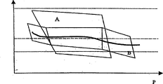
Fig. 2 has shown the relation of burner capacity and air ratio λ,
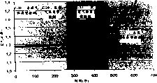
Fig. 3 has shown air ratio λ and the time relation under the different operating condition,
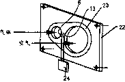
Fig. 4 a has shown the schematic part of control of the present invention and adjusting device to c,
Fig. 5 is the schematic sectional view of first air blast,
Fig. 6 is the schematic sectional view of second air blast,
Fig. 7 is the schematic sectional view of the 3rd air blast,
Fig. 8 is the schematic sectional view of the 4th air blast,
Fig. 9 is the schematic diagram that is provided with the air blast top of gas supply device at the air intake place,
Figure 10 is first schematic representation of apparatus that is used for measurement gas viscosity,
Figure 11 be used for measurement gas viscosity second schematic representation of apparatus and
Figure 12 is the 3rd schematic representation of apparatus that is used for measurement gas viscosity.
The specific embodiment
In Fig. 1, security solenoid valve or shutoff valve 2 in the supply pipeline 1 that is applicable to fuel gas or gas, have been connected.Shutoff valve 2 links to each other with data processing equipment 4 by first control line 3.Data processing equipment 4 can be assessment and control electronic unit, and it is equipped with the algorithm of the microprocessor and the permanent storage of assessment that is used for measurement data and control.The downstream of shutoff valve 2 is provided with the device 5 that is used for measurement gas viscosity, and it for example has the capillary (not shown) as flow impedance herein, and the splitter section of extracting out from the gas stream of laminar flow form is guided through this capillary.The pressure that utilizes suitable device for pressure measurement (also not shown) to measure on this capillary herein falls.From falling, measured pressure can determine Wobbe index or Wobbe number, calorific value and the caloric value of gas.Device for pressure measurement links to each other with data processing equipment 4 by first slotted line 6.First mass flow sensor 7 is positioned at after the device 5 that is used for measurement gas viscosity.This sensor for example is traditional hot wire sensor.Hot wire sensor comes the mass flow of measurement gas according to the duration (flying time) that acts on the thermal signal on the gas stream.First mass flow sensor 7 links to each other with data processing equipment 4 by second slotted line 8.First proportional valve 9 is positioned at after first mass flow sensor 7, and this first proportional valve links to each other with data processing equipment 4 by second control line 10.Gas supply pipe line 1 leads in the air supply pipe line 12 at branch point 11 places.Connected second mass flow sensor 13 in air supply pipe line 12, this sensor links to each other with data processing equipment 4 by the 3rd slotted line.Air blast identifies with label 15, and it is connected the downstream of the branch point 11 in the gas/air mixture pipeline 16.Air blast 15 links to each other with data processing equipment 4 by the 3rd control line 17.
Be provided with the burner 18 of band igniter 19 in the downstream of air blast 15, igniter 19 links to each other with data processing equipment 4 by the 4th control line 20.
To introduce the function of this device below.
Gas supply pipe line 1 can directly link to each other with gas line, and the mid portion that links to each other with pressure regulator promptly is not set.Can carry out leak detection afterwards.Shutoff valve 2 cuts out.Utilize first mass flow sensor 7 to determine whether shutoff valve 2 has correctly fastened gas supply pipe line 1.If this is the case, can open shutoff valve 2 through first control line 3 by suitable energisation mode so.Adopt device 5 on the distance of first proportional valve 9, measuring viscosity, and come the mass flow of measurement gas by first mass flow sensor 7.These two measured values are sent in the data processing equipment 4, and adopt the algorithm of appointment to assess there.Should consider various designated parameters (for example characteristic of burner 18).Can produce control impuls to the processing of installing the measurement result that 5 and first mass flow sensor 7 provided, control first proportional valve 9 by this control impuls, making can provide the gas flow that has constant calorific value in the time per unit at branch point 11 places.First proportional valve 9 can be pulse valve, rotary valve or piezo electric valve.The viscosity of gas or the deviation of mass flow can cause the instant variation in the cross section of first proportional valve 9, make that the given caloric value in the time per unit always keeps constant.The various pressure oscillations of gas line and the various variations of gas componant all can detect by suitable mode and be compensated.
Adopt second mass flow sensor 13 to measure the mass flow of air.Gas/air mixture is determined by air ratio λ.By air blast 15 is suitably controlled, just can set a kind of mode of operation of appointment according to data processing equipment 4, for example the fired state of burner.When having the gas of constant calorific value in time per unit is provided, the air ratio λ of appointment is just corresponding to air fed mass flow.Therefore, air ratio λ can set by the mass flow of air.The mass flow of air for example can be by air blast power, be that its speed is controlled, perhaps control by second proportional valve or the air valve (not shown herein) that are connected before or after the air blast.
In addition, also can regulate air ratio λ according to other parameter.The stability that suitable sensor obtains flame, the ability of burner 18 or the radiation that burning produced can be set in the zone of burner 18.This sensor (not shown herein) can link to each other with data processing equipment 4 by the 4th, the 5th or the 6th slotted line (not shown herein).For example, can control air ratio λ, make burner 18 stably remain on a certain ability, perhaps make radiation remain minimum so that flame keeps the stability of appointment.
Above-mentioned example should not be misinterpreted as it certainly and mean that described parts must arrange with described order.Naturally, also device 5, first mass flow sensor 7 and proportional valve 9 can be arranged with different order.In addition, also second mass flow sensor 13 and air blast 15 and the device relevant with branch point 11 can be arranged with different orders.
Fig. 2 has shown the relation between the performance P of air ratio λ and burner.The burner of having represented typical prior art by the operating area of A sign.Because the variation of gas type in the traditional operation process, this burner must guarantee to work safely in the scope of the relative broad of air ratio λ.It is too wide that available performance range P is that so-called modulation is not.When adopting method of the present invention or use to be applicable to the device of carrying out this method, can use set for can air ratio λ than close limit in the burner of working.When using method provided by the present invention, the variation of air ratio λ occurs in the limit value of appointment.Air ratio λ can not produce at random, do not wish the variation that takes place.The interior burner of working range that is set in the relative narrower of air ratio λ can be operated under lower radiation value.They embody the modulating performance of raising.In Fig. 2, indicated the operating area of this burner with B.
Air ratio λ and time relation in Fig. 3, have been shown.As a comparison, shown among the figure being provided with and not being provided with under the situation of apparatus of the present invention and changed to the burner of operating under the condition of G23 from G20 at gas type.If do not use device provided by the present invention, when gas type changed to G23, air ratio λ can increase to the location point that makes the fray-out of flame in the burner so.
Fig. 4 a has shown the schematic diagram of control provided by the present invention and adjusting device to c.The inlet plate 21 that links to each other with the air supply pipe line with gas has been installed in device.Be provided with intermediate plate 22 (it illustrates in greater detail) in Fig. 4 a in the downstream of inlet plate 21.Intermediate plate 22 has can be for the mouth of pipe of supply gas individually and air stream.First mass flow sensor 6 is positioned at the mouth of pipe that is used for gas stream, and second mass flow sensor 13 is positioned at the mouth of pipe that is used for air stream.The assessment electronic unit that label 23 expression seals, label 24 expressions and first mass flow sensor 6 link to each other with second mass flow sensor 13.Intermediate plate 22 (air hermetic ground) is installed in and is used for data processing equipment 4 or control and regulates the shell 25 of using electronic unit.Shell 25 comprises and is connected after the intermediate plate 22 and is in security solenoid valve 2 in the gas stream.Proportional valve 9 is installed in the downstream of magnetic valve 2 and is connected in the gas stream.The device 5 (not shown herein) that is used for measurement gas viscosity can be installed between security solenoid valve 2 and the proportional valve 9.Yet device 5 also can be the part of intermediate plate 22.Device shown in Fig. 4 b is applicable to the burner of being supported by air blast 18.Air blast 15 is connected on the gas/air mixture pipeline 16 of drawing from crust of the device 25.Can realize control by the capacity of control air blast 15 here to MAF.
Device shown in Fig. 4 c is applicable to the air ratio of setting atmospheric burner 18.In this case, in gas/air mixture pipeline 16, do not connect air blast.Another proportional valve (not shown herein) that is used to control MAF can be installed in shell, can control the mass flow of air by it.
Fig. 5 has shown the example of another air blast that is used for combustion air, and it can be used in so-called wall/floor type combustion furnace.This another air blast is made up of fan drum 26 and blast fan 27, and blast fan 27 has air intake 28 and air outlet slit 29.Air intake 28 is positioned at the suction side of air blast, and air outlet slit 29 is positioned on the pressure side.In example of the present invention shown in Figure 5, the gas supply pipe line is represented by label 1 equally.Be used for determining that second mass flow sensor 13 of MAF is in air intake 28.Second mass flow sensor 13 sends to control-regulon or data processing equipment 4 with signal, and it can control burning according to required thermal capacity, for example sets the relation between combustion medium and the combustion air.Second mass flow sensor 13 can be the airspeedometer of the MAF of electronic type, and it can obtain from the tradition source.
Shown in this example, except the jet gap 32 that is used for the air quality measurement, annular jet device 30 also has another jet gap 33 (gas jet gap) that is used for supply gas.
First mass flow sensor 7 is arranged in another jet gap 33, and it sends to data processing equipment 4 with the signal relevant with the mass flow of fuel gas.
If exist deviation with actual value, data processing equipment 4 just adopts the signal of MAF and the signal of gas mass flow to calculate suitable variable quantity, so that reach each required value.
Though mass flow sensor 7,13 are installed in available pipeline or the annular jet part as independent parts shown in example among Fig. 5, yet also can design the mass flow sensor 7 as shown in example among Fig. 6,13, it makes to have common dividing wall between the annular jet device of the mass flow measurement that is used for air, and flow obtains by measuring chip.This has just formed the compact structure unit.
Fig. 7 has shown another example of air blast.Input channel 35 is positioned at before the annular jet device 30.In this form, second mass flow sensor 13 that is used for MAF is positioned at the branch line 31 that leads to input channel 35.Be provided with the circulating line that is capped 37 that is positioned at before the annular gap 36 in input channel 35, branch line 31 leads in this circulating line.The swabbing action of annular can realize suction uniformly to the measurement volumes of the mass flow of passing branch line 31.
In the example depicted in fig. 8, branch line 31 is designed to make its opening generally perpendicularly to point to the wall of input channel 35.
Fig. 8 has shown the example of rotary valve/control valve 38, and this valve can be used for actuating in all other the pattern and by data processing unit 4.Rotary valve/control valve 38 is integral parts of air blast.Shown in form in, rotary valve/control valve 38 is designed to the suction side supply gas at air blast.
As the example that can be used for all other patterns, Fig. 8 has shown blower motor 39, and wherein data processing equipment 4 is handled the assessment and the motor commutation of mass flow, and the speed of regulating blower motor in view of the above.This control is designed to electronic unit or adjustments of gas supply under the constant speed of motor 39, perhaps relatively comes suitably to regulate the speed and the gas supply of motor according to the continuous set point/actual value of desired volume.
Fig. 9 has shown the side view of structure provided by the present invention, and wherein gas supplies with 1 and occur on the air intake without the annular jet device, but occur on the air outlet slit on the pressure side near.
The present invention is not limited to above-mentioned preferred exemplary.On the contrary, even under the visibly different situation of model, also can utilize described plan plot to go out many modification.
Figure 10 to 12 has shown the schematic diagram of the different examples of the device 5 that is used to measure viscosity.
The measurement that device 5 permissions shown in Figure 11 are interrupted dynamic viscosity.Piston pump 44 is connected in the branch line 40.Utilizing after piston pump carries out the measurement of first pattern, the gaseous samples pressurization of extracting out from branch line 40 by 44 pairs of piston pumps reaches a certain amount of time, makes it flow through capillary 42 with constant volume flow.Employing device for pressure measurement 43 is measured the pressure differential on the capillary.As device shown in Figure 10, can come to determine the dynamic viscosity of gas thus.In second pattern, increase the speed of piston pump 44, the pressure differential on capillary 42 reach the measure error of device for pressure measurement 43 when low especially till.Determine the feed speed of piston pump 44 at this moment.Determine the dynamic viscosity of gas then thus.
As for another device 5 shown in Figure 12, the measurement of dynamic viscosity is carried out based on known volume.Gas bleeding sample from branch line 40, and be pumped in the chamber 45 by micropump 41.When filling chamber 45, first valve 46 is opened and second valve 47 cuts out.In case chamber 45 is filled, first valve 46 is also closed.Second valve 47 is opened then.Gas flows through capillary 42, and the pressure in chamber 45 equals till the pressure in the gas supply pipe line 1.Device for pressure measurement 43 is used for the speed that gaging pressure descends.Can determine dynamic viscosity thus.
Label list
1 gas supply pipe line
2 shutoff valves
3 first control lines
4 data processing equipments
5 are used for measuring the device of viscosity
6 first slotted lines
7 first mass flow sensors
8 second slotted lines
9 first proportional valves
10 second control lines
11 branch points
12 air supply pipelines
13 second mass flow sensors
14 the 3rd slotted lines
15 air blasts
16 gas/air mixture pipelines
17 the 3rd control lines
18 burners
19 igniters
20 the 4th control lines
21 inlet plates
22 intermediate plates
23 seals
24 assessment electronic units
25 shells
26 fan drums
27 blast fans
28 air intakes
29 air outlet slits
30 annular jet devices
31 branch lines
32 jet gaps
33 another jet gaps
34 shell walls
35 input channels
36 annular gaps
37 circulating lines
38 rotary valves/control valve
39 motor
40 another branch lines
41 micropumps
42 capillaries
43 device for pressure measurement
44 piston pumps
45 chambeies
46 first valves
47 second valves
Claims (32)
1. a method that is used for setting for the air ratio λ of the fuel/air mixture of being made up of gaseous fuel and air of burner (18) operation usefulness is characterized in that,
A) the quality of fuel flow is defined as first measured value,
B) value that will be used for determining the Wobbe index of fuel is defined as second measured value, the wherein said step of determining second measured value comprises by a part of fuel guiding is determined the viscosity of fuel by a capillary with by measuring the speed that pressure falls or pressure falls that capillary causes
C) mass flow of air is defined as the 3rd measured value and
D) control air and/or quality of fuel flow according at least two described measured values, thereby set the appointment air ratio λ of described fuel/air mixture.
2. method according to claim 1 is characterized in that, comes the mass flow of described air is controlled according to described measured value in described steps d.
3. each described method in requiring according to aforesaid right, it is characterized in that, described measured value is sent in the data processing equipment (4), algorithm according to appointment is handled, and regulates described quality of fuel flow by described data processing equipment (4) with first proportional valve (9) that is connected in the described fuel stream.
4. method according to claim 3 is characterized in that, the mass flow of described air is controlled by air blast (15), air valve and/or second proportional valve.
5. require 1 described method according to aforesaid right, it is characterized in that, regulate described air ratio λ according to the stability of the flame that in described burner (18), produces.
6. require 1 described method according to aforesaid right, it is characterized in that, regulate described air ratio λ according to the appointment thermal capacity of described burner (18).
7. require 1 described method according to aforesaid right, it is characterized in that, can regulate described air ratio λ so that the radiation minimum that is produced in the combustion process.
8. require 1 described method according to aforesaid right, it is characterized in that, regulate described quality of fuel flow, make the given caloric value of the fuel that in time per unit, is supplied to described burner (18) keep constant according to described first and second measured values.
9. require 1 described method according to aforesaid right, it is characterized in that, the viscosity of described fuel is defined as second measured value.
10. one kind is used for the device that enforcement of rights requires 1 described method, it is characterized in that,
First mass flow sensor that is used for determining first measured value, the device (5) that is used to measure second measured value that to determine Wobbe index in fuel feed pipe line (1), have been connected, described device (5) comprises that a capillary (42) and a device for pressure measurement (43) are used to measure the pressure that capillary causes and fall or pressure reduction of speed degree, and first proportional valve (9)
In air supply pipe line (12), connected second mass flow sensor (13) that is used for determining the 3rd measured value,
Be provided with the device (15) of the mass flow of the described air of control,
Be provided with data processing equipment (4), be used for regulating described quality of fuel flow by described first proportional valve (9), described quality of fuel flow is regulated according to described first and second measured values, make the given caloric value of the fuel that offers described burner (18) in the time per unit keep constant, and
Can control the mass flow of described air according at least two described measured values and by described data processing equipment (4), thereby set the air ratio λ of appointment.
11. device according to claim 10 is characterized in that, controls the mass flow of described air according to described measured value.
12. device according to claim 10 is characterized in that, the device (5) that is used to measure described second measured value is the device that is used to measure viscosity.
13. device according to claim 10 is characterized in that, the device of the mass flow of described adjusting air is equipped with air blast (15), air valve and/or second proportional valve.
14. device according to claim 10, it is characterized in that, a kind of device that is used for being identified in the stability of the flame that described burner produces is provided, and the 4th measured value that can record according to this device also be regulated described air ratio λ by described data processing equipment (4).
15. device according to claim 10, it is characterized in that, a kind of device that is used to measure the thermal capacity of described burner (18) is provided, and the 5th measured value that records according to this device is also regulated described air ratio λ by described data processing equipment (4).
16. device according to claim 10, it is characterized in that, a kind of device that measuring radiation is polluted content that is used for is provided, can also regulate described air ratio λ according to the 6th measured value that this device records, feasible burning produced pollution content minimum by described data processing equipment (4).
17. device according to claim 10, it is characterized in that, a kind of air blast that is used for the air of wall surface type/floor type combustion furnace is provided, it has fan drum (26) and blast fan (27), described impeller (27) has air intake (28) and air outlet slit (29), also has the fuel feed pipe line (1) that is used for fuel, wherein, second mass flow sensor (13) that is used for the mass flow of definite described air is positioned at described air intake (28), it links to each other with described data processing equipment (4) on function and sends a signal to described data processing equipment, is used for calculating according to required thermal capacity the ratio of combustion medium and combustion air.
18. device according to claim 17 is characterized in that, described second mass flow sensor (13) is the airspeedometer of the MAF of electronic type.
19. device according to claim 18 is characterized in that, is provided with annular jet device (30) on described air intake (28).
20. device according to claim 19 is characterized in that, described second mass flow sensor (13) is positioned on the described annular jet device (30).
21. device according to claim 20 is characterized in that, described second mass flow sensor (13) is arranged in a branch line (31), and described branch line leads in the jet gap (32) of described annular jet device (30).
22. device according to claim 21 is characterized in that, except the jet gap (32) that is used for the air quality measurement, described annular jet device (30) also has another jet gap (33) that is used for fuel supplying.
23. device according to claim 22 is characterized in that, first mass flow sensor (7) is positioned at the zone in described another jet gap (33), and it sends to described data processing equipment (4) with appropriate signals.
24. device according to claim 19 is characterized in that, described annular jet device (30) is an integral part of the shell wall (34) located of the air intake (28) of described air blast.
25. device according to claim 19 is characterized in that, described annular jet device (30) has surrounded the main flow part of the combustion air that described air intake (28) locates.
26. device according to claim 21 is characterized in that, is provided with input channel (35) before at described annular jet device (30).
27. device according to claim 26 is characterized in that, described branch line (31) leads in the described input channel (35).
28. device according to claim 27 is characterized in that, described branch line (31) leads in the interior annular gap (36) of described input channel (35).
29. device according to claim 17 is characterized in that, a rotary valve/control valve (38) that is used for supply gas is an integral part of described fan drum.
30. device according to claim 29 is characterized in that, the described rotary valve/control valve (38) that is used for supply gas is positioned at the suction side of described air blast.
31. device according to claim 10 is characterized in that, adopts an electronic motor to commutate and handles the assessment of mass flow, and regulate the speed of a blower motor.
32. device according to claim 31 is characterized in that, described electronic motor commutates and handles the assessment of mass flow, and regulates the speed and the air supply of described blower motor.
Applications Claiming Priority (4)
| Application Number | Priority Date | Filing Date | Title |
|---|---|---|---|
| DE10114405A DE10114405B4 (en) | 2001-03-23 | 2001-03-23 | Blower for combustion air |
| DE10114405.9 | 2001-03-23 | ||
| DE10114901.8 | 2001-03-26 | ||
| DE10114901A DE10114901A1 (en) | 2001-03-26 | 2001-03-26 | Method and device for adjusting the air ratio of a fuel air mixture, measures mass flows and wobbe index and adjusts to give predetermined lambda |
Related Child Applications (1)
| Application Number | Title | Priority Date | Filing Date |
|---|---|---|---|
| CNB2005101036834A Division CN100464124C (en) | 2001-03-23 | 2002-03-22 | Blower for combustion air |
Publications (2)
| Publication Number | Publication Date |
|---|---|
| CN1509391A CN1509391A (en) | 2004-06-30 |
| CN1228568C true CN1228568C (en) | 2005-11-23 |
Family
ID=26008879
Family Applications (1)
| Application Number | Title | Priority Date | Filing Date |
|---|---|---|---|
| CNB028101642A Expired - Fee Related CN1228568C (en) | 2001-03-23 | 2002-03-22 | Method and apparatus for setting air ratio |
Country Status (7)
| Country | Link |
|---|---|
| US (2) | US6939127B2 (en) |
| EP (1) | EP1370806B1 (en) |
| JP (2) | JP2004522129A (en) |
| CN (1) | CN1228568C (en) |
| AT (1) | ATE476628T1 (en) |
| DE (1) | DE50214567D1 (en) |
| WO (1) | WO2002077528A1 (en) |
Families Citing this family (59)
| Publication number | Priority date | Publication date | Assignee | Title |
|---|---|---|---|---|
| DE19918901C1 (en) * | 1999-04-26 | 2001-05-03 | Franz Durst | Device for setting the oxidant / fuel mixture in the feed line of a burner |
| DE10348324B3 (en) * | 2003-10-17 | 2005-05-25 | Gvp Gesellschaft Zur Vermarktung Der Porenbrennertechnik Mbh | Modulation process for heating load of burner involves preparing measuring lines, measuring volume and mass flow of gas and air and producing required gas mixture |
| DE10349344B3 (en) | 2003-10-23 | 2005-06-30 | Ebm-Papst Landshut Gmbh | Blower with laminar element in front of the suction opening |
| KR101157652B1 (en) * | 2004-06-23 | 2012-06-18 | 에베엠-파프스트 란드스후트 게엠베하 | Method for adjusting the excess air coefficient on a firing apparatus, and firing apparatus |
| DE102004055716C5 (en) * | 2004-06-23 | 2010-02-11 | Ebm-Papst Landshut Gmbh | Method for controlling a firing device and firing device (electronic composite I) |
| WO2006101991A2 (en) * | 2005-03-17 | 2006-09-28 | Southwest Research Institute | Mass air flow compensation for burner-based exhaust gas generation system |
| US20070154856A1 (en) * | 2006-01-03 | 2007-07-05 | Raymond Hallit | Dual fuel boiler with backflow-preventing valve arrangement |
| US7856853B2 (en) * | 2006-02-01 | 2010-12-28 | Owens Corning Intellectual Capital, Llc | Rotary process for making mineral fiber insulation material |
| US8105077B2 (en) * | 2007-08-17 | 2012-01-31 | Red-Ray Manufacturing, Co., Inc. | Integrated operating and control package for a pressurized burner system |
| EP2048439B1 (en) * | 2007-10-12 | 2014-06-18 | ebm-papst Landshut GmbH | Ventilator with integrated control valve |
| JP2009162128A (en) * | 2008-01-08 | 2009-07-23 | Yamatake Corp | Fuel supply device |
| US9317046B2 (en) * | 2008-07-03 | 2016-04-19 | Mike Gum | Variable output heating control system |
| US20100205976A1 (en) * | 2008-08-26 | 2010-08-19 | Pratyush Nag | Integrated fuel gas characterization system |
| US8484981B2 (en) * | 2008-08-26 | 2013-07-16 | Siemens Energy, Inc. | Integrated fuel gas characterization system |
| US8286594B2 (en) * | 2008-10-16 | 2012-10-16 | Lochinvar, Llc | Gas fired modulating water heating appliance with dual combustion air premix blowers |
| BE1018339A3 (en) * | 2008-11-18 | 2010-09-07 | Bodart Et Gonay | SYSTEM OF AIR SUPPLY AND EXHAUST OF BURNED GASES. |
| US8302324B1 (en) * | 2009-05-26 | 2012-11-06 | Stella Sharon Connelly | Oscillating hair dryer |
| DE202010018511U1 (en) * | 2010-03-10 | 2017-03-24 | Ebm-Papst Landshut Gmbh | Pneumatic compound with mass balance |
| DE102011117736A1 (en) | 2011-11-07 | 2013-05-08 | Honeywell Technologies Sarl | Method for operating a gas burner |
| US8839815B2 (en) | 2011-12-15 | 2014-09-23 | Honeywell International Inc. | Gas valve with electronic cycle counter |
| US8905063B2 (en) | 2011-12-15 | 2014-12-09 | Honeywell International Inc. | Gas valve with fuel rate monitor |
| US9074770B2 (en) | 2011-12-15 | 2015-07-07 | Honeywell International Inc. | Gas valve with electronic valve proving system |
| US9557059B2 (en) | 2011-12-15 | 2017-01-31 | Honeywell International Inc | Gas valve with communication link |
| US9851103B2 (en) | 2011-12-15 | 2017-12-26 | Honeywell International Inc. | Gas valve with overpressure diagnostics |
| US9835265B2 (en) | 2011-12-15 | 2017-12-05 | Honeywell International Inc. | Valve with actuator diagnostics |
| US9995486B2 (en) | 2011-12-15 | 2018-06-12 | Honeywell International Inc. | Gas valve with high/low gas pressure detection |
| US8899264B2 (en) | 2011-12-15 | 2014-12-02 | Honeywell International Inc. | Gas valve with electronic proof of closure system |
| US8947242B2 (en) | 2011-12-15 | 2015-02-03 | Honeywell International Inc. | Gas valve with valve leakage test |
| US9846440B2 (en) | 2011-12-15 | 2017-12-19 | Honeywell International Inc. | Valve controller configured to estimate fuel comsumption |
| KR101915196B1 (en) * | 2012-05-18 | 2018-11-05 | 한화에어로스페이스 주식회사 | Gas turbine system |
| US9234661B2 (en) | 2012-09-15 | 2016-01-12 | Honeywell International Inc. | Burner control system |
| US10422531B2 (en) | 2012-09-15 | 2019-09-24 | Honeywell International Inc. | System and approach for controlling a combustion chamber |
| ITMI20122008A1 (en) * | 2012-11-27 | 2014-05-28 | Polidoro Spa | DEVICE FOR THE MANAGEMENT OF THE COMBUSTIBLE / FUEL REPORT OF THERMOTECHNICAL PLANTS. |
| EP2789915A1 (en) * | 2013-04-10 | 2014-10-15 | Alstom Technology Ltd | Method for operating a combustion chamber and combustion chamber |
| EP2868970B1 (en) | 2013-10-29 | 2020-04-22 | Honeywell Technologies Sarl | Regulating device |
| US10024439B2 (en) | 2013-12-16 | 2018-07-17 | Honeywell International Inc. | Valve over-travel mechanism |
| US9841122B2 (en) | 2014-09-09 | 2017-12-12 | Honeywell International Inc. | Gas valve with electronic valve proving system |
| US9645584B2 (en) | 2014-09-17 | 2017-05-09 | Honeywell International Inc. | Gas valve with electronic health monitoring |
| US10503181B2 (en) | 2016-01-13 | 2019-12-10 | Honeywell International Inc. | Pressure regulator |
| CN105758206A (en) * | 2016-03-16 | 2016-07-13 | 东旭科技集团有限公司 | Total heat control method and system for kiln temperature |
| CN105953408A (en) * | 2016-06-29 | 2016-09-21 | 佛山市顺德区奇林电气有限公司 | Adjusting method and adjusting device for precise air inflow |
| US10274195B2 (en) * | 2016-08-31 | 2019-04-30 | Honeywell International Inc. | Air/gas admittance device for a combustion appliance |
| PL3301362T3 (en) | 2016-09-30 | 2020-08-24 | Siemens Aktiengesellschaft | Method of controlling turbulent flows |
| EP3301363B1 (en) * | 2016-09-30 | 2019-08-28 | Siemens Aktiengesellschaft | Combustion unit with a burner and flow measurement of turbulent flows |
| US10564062B2 (en) | 2016-10-19 | 2020-02-18 | Honeywell International Inc. | Human-machine interface for gas valve |
| CN106765334A (en) * | 2016-12-06 | 2017-05-31 | 江门市永成厨具设备有限公司 | A kind of boiler |
| US20180180586A1 (en) * | 2016-12-22 | 2018-06-28 | COSA Xentaur Corporation | Zero emission wobbe analyzer |
| CN107255274A (en) * | 2017-05-24 | 2017-10-17 | 江苏师范大学 | A kind of low nitrogen burner for gas boiler |
| CN107352274A (en) * | 2017-08-25 | 2017-11-17 | 天津商业大学 | A kind of regulatable new induction Pneumatic conveyer of particle concentration |
| DE102017009393B3 (en) * | 2017-10-11 | 2019-01-24 | Promecon Process Measurement Control Gmbh | Device for controlling the combustion process in a power plant furnace |
| US10718518B2 (en) | 2017-11-30 | 2020-07-21 | Brunswick Corporation | Systems and methods for avoiding harmonic modes of gas burners |
| US11073281B2 (en) | 2017-12-29 | 2021-07-27 | Honeywell International Inc. | Closed-loop programming and control of a combustion appliance |
| US10697815B2 (en) | 2018-06-09 | 2020-06-30 | Honeywell International Inc. | System and methods for mitigating condensation in a sensor module |
| US11441772B2 (en) | 2018-07-19 | 2022-09-13 | Brunswick Corporation | Forced-draft pre-mix burner device |
| US11486576B2 (en) * | 2019-08-23 | 2022-11-01 | Regal Beloit America, Inc. | System and method for burner ignition using sensorless constant mass flow draft inducers |
| CN110566962A (en) * | 2019-09-26 | 2019-12-13 | 佛山市通润热能科技有限公司 | Combustion control method of heat accumulating type single-burner aluminum melting furnace with adjustable air-fuel ratio |
| US11608983B2 (en) | 2020-12-02 | 2023-03-21 | Brunswick Corporation | Gas burner systems and methods for calibrating gas burner systems |
| EP4033148B1 (en) | 2021-01-25 | 2023-11-01 | Pittway Sarl | Method and controller for operating a gas burner appliance |
| US11940147B2 (en) | 2022-06-09 | 2024-03-26 | Brunswick Corporation | Blown air heating system |
Family Cites Families (20)
| Publication number | Priority date | Publication date | Assignee | Title |
|---|---|---|---|---|
| DE2928739C2 (en) | 1979-07-17 | 1981-03-19 | Ruhrgas Ag, 4300 Essen | Method and device for combustion-free measurement and / or control of the amount of heat supplied to gas consumption devices |
| US4359284A (en) * | 1981-03-17 | 1982-11-16 | Honeywell Inc. | Method and apparatus for determining the Wobbe index of gaseous fuels |
| NL8104308A (en) | 1981-09-18 | 1983-04-18 | Nederlandse Gasunie Nv | METHOD AND APPARATUS FOR KEEPING THE CALORIC TAX OF GAS APPLIANCES CONSTANTLY |
| DE3502008A1 (en) * | 1985-01-23 | 1986-07-24 | Standard Elektrik Lorenz Ag, 7000 Stuttgart | EXPANSION SENSOR |
| EP0204928B1 (en) * | 1985-04-18 | 1991-07-24 | Matsushita Electric Industrial Co., Ltd. | Exciting of magnetic field for amorphous-alloy sensor |
| US4924711A (en) * | 1989-02-10 | 1990-05-15 | National Research Development Corporation | Force transducers for use in arrays |
| CA2072122A1 (en) * | 1989-10-30 | 1991-05-01 | Ulrich Bonne | Microbridge-based combustion control |
| JPH04309713A (en) * | 1991-04-05 | 1992-11-02 | Paloma Ind Ltd | Multi gas combustion device |
| EP0554095A3 (en) * | 1992-01-30 | 1994-12-14 | Honeywell Inc | Determination of fuel characteristics |
| JP2943544B2 (en) * | 1992-12-11 | 1999-08-30 | トヨタ自動車株式会社 | Gas turbine generator |
| DE4336174C2 (en) | 1993-10-22 | 2003-09-18 | Ruhrgas Ag | Process for the combustion-free measurement and / or regulation of the supply of heat to gas consumption devices |
| JPH07243640A (en) * | 1994-03-08 | 1995-09-19 | Toto Ltd | Combustion controller |
| JP3534865B2 (en) * | 1994-12-27 | 2004-06-07 | 株式会社ガスター | Air-fuel ratio control device for combustor |
| DE19629220B4 (en) * | 1996-07-19 | 2005-05-12 | Motoren Ventilatoren Landshut Gmbh | High Pressure Blower |
| JP3736929B2 (en) * | 1997-03-27 | 2006-01-18 | 株式会社ガスター | Combustion device |
| JPH1194244A (en) * | 1997-09-18 | 1999-04-09 | Gastar Corp | Combustion device |
| DE19853567A1 (en) | 1998-11-20 | 2000-05-25 | Kromschroeder Ag G | Process for controlling the air ratio of a fully premixed gas burner |
| DE19918901C1 (en) | 1999-04-26 | 2001-05-03 | Franz Durst | Device for setting the oxidant / fuel mixture in the feed line of a burner |
| US6639402B2 (en) * | 2001-01-31 | 2003-10-28 | University Of Kentucky Research Foundation | Temperature, stress, and corrosive sensing apparatus utilizing harmonic response of magnetically soft sensor element (s) |
| DE10145592C1 (en) * | 2001-09-14 | 2003-06-18 | Rational Ag | Method for setting the power of gas-operated cooking appliances and cooking appliance using this method |
-
2002
- 2002-03-22 US US10/472,660 patent/US6939127B2/en not_active Expired - Fee Related
- 2002-03-22 CN CNB028101642A patent/CN1228568C/en not_active Expired - Fee Related
- 2002-03-22 DE DE50214567T patent/DE50214567D1/en not_active Expired - Lifetime
- 2002-03-22 WO PCT/EP2002/003253 patent/WO2002077528A1/en not_active Application Discontinuation
- 2002-03-22 AT AT02727462T patent/ATE476628T1/en active
- 2002-03-22 EP EP02727462A patent/EP1370806B1/en not_active Expired - Lifetime
- 2002-03-22 JP JP2002575538A patent/JP2004522129A/en active Pending
-
2005
- 2005-06-17 US US11/155,350 patent/US7223094B2/en not_active Expired - Lifetime
-
2007
- 2007-11-30 JP JP2007311526A patent/JP4928426B2/en not_active Expired - Fee Related
Also Published As
| Publication number | Publication date |
|---|---|
| ATE476628T1 (en) | 2010-08-15 |
| US20050255418A1 (en) | 2005-11-17 |
| US7223094B2 (en) | 2007-05-29 |
| US6939127B2 (en) | 2005-09-06 |
| EP1370806B1 (en) | 2010-08-04 |
| US20040106078A1 (en) | 2004-06-03 |
| JP4928426B2 (en) | 2012-05-09 |
| DE50214567D1 (en) | 2010-09-16 |
| JP2004522129A (en) | 2004-07-22 |
| EP1370806A1 (en) | 2003-12-17 |
| CN1509391A (en) | 2004-06-30 |
| WO2002077528A1 (en) | 2002-10-03 |
| JP2008101909A (en) | 2008-05-01 |
Similar Documents
| Publication | Publication Date | Title |
|---|---|---|
| CN1228568C (en) | Method and apparatus for setting air ratio | |
| CN1737428A (en) | Blower for combustion air | |
| CN1040514C (en) | Working head and laser working apparatus | |
| CN100338236C (en) | Heating furnace with regenerative burners and method of operating heating furnace | |
| US8417434B2 (en) | Active pattern factor control for gas turbine engines | |
| CN1270067C (en) | Apparatus for controlling internal combustion engine | |
| CN86106698A (en) | Air/fuel ratio detecting apparatus for internal combustion engines | |
| SU1738102A3 (en) | Multichamber furnace for caking carbon-containing blocks and burning control method | |
| GB2226163A (en) | Air/fuel ratio control for a burner | |
| CN1351700A (en) | Device for adjusting oxidation agent/fuel mixture in feeding pipe of burner | |
| CN103147860A (en) | Method and apparatus for gas turbine dry low NOx combustor corrected parameter control | |
| SE507834C2 (en) | Method and apparatus for controlling the fuel / air ratio of the combustion gas supply of a radiant burner | |
| CN1637255A (en) | Engine controller | |
| CN1611766A (en) | Fuel jet device for IC engine and method and fuel jet valve | |
| CN1222714C (en) | Fireroom temp. control method cable of making discharge of carbon monoxide reach standard and energy consume minimum | |
| CN107882613B (en) | Reduce the device of engine motor oil consumption and particulate emission | |
| JP4854505B2 (en) | Noise control method for heat engine | |
| CN106439821A (en) | Civil combustor test device and combustor test method applying same | |
| CN1688367A (en) | Fire extinguishing training exercise system | |
| CN1693755A (en) | Heating furnace with regenerative burners and method of operating heating furnace | |
| KR19990055427A (en) | Sintered ore device and sintered ore manufacturing method | |
| CN1875177A (en) | Control system of an internal combustion engine | |
| JP2000169214A (en) | Gas ceramic art kiln | |
| JPH06299158A (en) | Apparatus for producing powdery charcoal | |
| WO2005043038A2 (en) | Method and apparatus for introducing a fuel mixture containing methane and an aggregate of air and coal dust, into a combustion chamber and/or of a kiln |
Legal Events
| Date | Code | Title | Description |
|---|---|---|---|
| C06 | Publication | ||
| PB01 | Publication | ||
| C10 | Entry into substantive examination | ||
| SE01 | Entry into force of request for substantive examination | ||
| C14 | Grant of patent or utility model | ||
| GR01 | Patent grant | ||
| C17 | Cessation of patent right | ||
| CF01 | Termination of patent right due to non-payment of annual fee |
Granted publication date: 20051123 Termination date: 20100322 |