EP3290597A1 - Procédé de commande d'une soupape de commande principale d'un excavateur et appareil à cet effet - Google Patents
Procédé de commande d'une soupape de commande principale d'un excavateur et appareil à cet effet Download PDFInfo
- Publication number
- EP3290597A1 EP3290597A1 EP17187385.4A EP17187385A EP3290597A1 EP 3290597 A1 EP3290597 A1 EP 3290597A1 EP 17187385 A EP17187385 A EP 17187385A EP 3290597 A1 EP3290597 A1 EP 3290597A1
- Authority
- EP
- European Patent Office
- Prior art keywords
- arm
- boom
- joystick
- cylinder
- flux
- Prior art date
- Legal status (The legal status is an assumption and is not a legal conclusion. Google has not performed a legal analysis and makes no representation as to the accuracy of the status listed.)
- Granted
Links
Images


Classifications
-
- E—FIXED CONSTRUCTIONS
- E02—HYDRAULIC ENGINEERING; FOUNDATIONS; SOIL SHIFTING
- E02F—DREDGING; SOIL-SHIFTING
- E02F9/00—Component parts of dredgers or soil-shifting machines, not restricted to one of the kinds covered by groups E02F3/00 - E02F7/00
- E02F9/20—Drives; Control devices
- E02F9/22—Hydraulic or pneumatic drives
- E02F9/2264—Arrangements or adaptations of elements for hydraulic drives
-
- E—FIXED CONSTRUCTIONS
- E02—HYDRAULIC ENGINEERING; FOUNDATIONS; SOIL SHIFTING
- E02F—DREDGING; SOIL-SHIFTING
- E02F9/00—Component parts of dredgers or soil-shifting machines, not restricted to one of the kinds covered by groups E02F3/00 - E02F7/00
- E02F9/20—Drives; Control devices
- E02F9/22—Hydraulic or pneumatic drives
- E02F9/2221—Control of flow rate; Load sensing arrangements
- E02F9/2225—Control of flow rate; Load sensing arrangements using pressure-compensating valves
-
- E—FIXED CONSTRUCTIONS
- E02—HYDRAULIC ENGINEERING; FOUNDATIONS; SOIL SHIFTING
- E02F—DREDGING; SOIL-SHIFTING
- E02F9/00—Component parts of dredgers or soil-shifting machines, not restricted to one of the kinds covered by groups E02F3/00 - E02F7/00
- E02F9/20—Drives; Control devices
- E02F9/2004—Control mechanisms, e.g. control levers
-
- E—FIXED CONSTRUCTIONS
- E02—HYDRAULIC ENGINEERING; FOUNDATIONS; SOIL SHIFTING
- E02F—DREDGING; SOIL-SHIFTING
- E02F9/00—Component parts of dredgers or soil-shifting machines, not restricted to one of the kinds covered by groups E02F3/00 - E02F7/00
- E02F9/20—Drives; Control devices
- E02F9/22—Hydraulic or pneumatic drives
- E02F9/2221—Control of flow rate; Load sensing arrangements
- E02F9/2239—Control of flow rate; Load sensing arrangements using two or more pumps with cross-assistance
- E02F9/2242—Control of flow rate; Load sensing arrangements using two or more pumps with cross-assistance including an electronic controller
-
- E—FIXED CONSTRUCTIONS
- E02—HYDRAULIC ENGINEERING; FOUNDATIONS; SOIL SHIFTING
- E02F—DREDGING; SOIL-SHIFTING
- E02F9/00—Component parts of dredgers or soil-shifting machines, not restricted to one of the kinds covered by groups E02F3/00 - E02F7/00
- E02F9/20—Drives; Control devices
- E02F9/22—Hydraulic or pneumatic drives
- E02F9/2278—Hydraulic circuits
- E02F9/2292—Systems with two or more pumps
-
- F—MECHANICAL ENGINEERING; LIGHTING; HEATING; WEAPONS; BLASTING
- F15—FLUID-PRESSURE ACTUATORS; HYDRAULICS OR PNEUMATICS IN GENERAL
- F15B—SYSTEMS ACTING BY MEANS OF FLUIDS IN GENERAL; FLUID-PRESSURE ACTUATORS, e.g. SERVOMOTORS; DETAILS OF FLUID-PRESSURE SYSTEMS, NOT OTHERWISE PROVIDED FOR
- F15B11/00—Servomotor systems without provision for follow-up action; Circuits therefor
- F15B11/16—Servomotor systems without provision for follow-up action; Circuits therefor with two or more servomotors
- F15B11/17—Servomotor systems without provision for follow-up action; Circuits therefor with two or more servomotors using two or more pumps
-
- F—MECHANICAL ENGINEERING; LIGHTING; HEATING; WEAPONS; BLASTING
- F15—FLUID-PRESSURE ACTUATORS; HYDRAULICS OR PNEUMATICS IN GENERAL
- F15B—SYSTEMS ACTING BY MEANS OF FLUIDS IN GENERAL; FLUID-PRESSURE ACTUATORS, e.g. SERVOMOTORS; DETAILS OF FLUID-PRESSURE SYSTEMS, NOT OTHERWISE PROVIDED FOR
- F15B13/00—Details of servomotor systems ; Valves for servomotor systems
- F15B13/02—Fluid distribution or supply devices characterised by their adaptation to the control of servomotors
- F15B13/06—Fluid distribution or supply devices characterised by their adaptation to the control of servomotors for use with two or more servomotors
-
- B—PERFORMING OPERATIONS; TRANSPORTING
- B60—VEHICLES IN GENERAL
- B60Y—INDEXING SCHEME RELATING TO ASPECTS CROSS-CUTTING VEHICLE TECHNOLOGY
- B60Y2200/00—Type of vehicle
- B60Y2200/40—Special vehicles
- B60Y2200/41—Construction vehicles, e.g. graders, excavators
- B60Y2200/412—Excavators
-
- E—FIXED CONSTRUCTIONS
- E02—HYDRAULIC ENGINEERING; FOUNDATIONS; SOIL SHIFTING
- E02F—DREDGING; SOIL-SHIFTING
- E02F3/00—Dredgers; Soil-shifting machines
- E02F3/04—Dredgers; Soil-shifting machines mechanically-driven
- E02F3/28—Dredgers; Soil-shifting machines mechanically-driven with digging tools mounted on a dipper- or bucket-arm, i.e. there is either one arm or a pair of arms, e.g. dippers, buckets
- E02F3/36—Component parts
- E02F3/42—Drives for dippers, buckets, dipper-arms or bucket-arms
- E02F3/425—Drive systems for dipper-arms, backhoes or the like
-
- E—FIXED CONSTRUCTIONS
- E02—HYDRAULIC ENGINEERING; FOUNDATIONS; SOIL SHIFTING
- E02F—DREDGING; SOIL-SHIFTING
- E02F9/00—Component parts of dredgers or soil-shifting machines, not restricted to one of the kinds covered by groups E02F3/00 - E02F7/00
- E02F9/20—Drives; Control devices
- E02F9/22—Hydraulic or pneumatic drives
- E02F9/2264—Arrangements or adaptations of elements for hydraulic drives
- E02F9/2267—Valves or distributors
-
- F—MECHANICAL ENGINEERING; LIGHTING; HEATING; WEAPONS; BLASTING
- F15—FLUID-PRESSURE ACTUATORS; HYDRAULICS OR PNEUMATICS IN GENERAL
- F15B—SYSTEMS ACTING BY MEANS OF FLUIDS IN GENERAL; FLUID-PRESSURE ACTUATORS, e.g. SERVOMOTORS; DETAILS OF FLUID-PRESSURE SYSTEMS, NOT OTHERWISE PROVIDED FOR
- F15B2211/00—Circuits for servomotor systems
- F15B2211/20—Fluid pressure source, e.g. accumulator or variable axial piston pump
- F15B2211/205—Systems with pumps
- F15B2211/20576—Systems with pumps with multiple pumps
-
- F—MECHANICAL ENGINEERING; LIGHTING; HEATING; WEAPONS; BLASTING
- F15—FLUID-PRESSURE ACTUATORS; HYDRAULICS OR PNEUMATICS IN GENERAL
- F15B—SYSTEMS ACTING BY MEANS OF FLUIDS IN GENERAL; FLUID-PRESSURE ACTUATORS, e.g. SERVOMOTORS; DETAILS OF FLUID-PRESSURE SYSTEMS, NOT OTHERWISE PROVIDED FOR
- F15B2211/00—Circuits for servomotor systems
- F15B2211/30—Directional control
- F15B2211/305—Directional control characterised by the type of valves
- F15B2211/3056—Assemblies of multiple valves
- F15B2211/3059—Assemblies of multiple valves having multiple valves for multiple output members
-
- F—MECHANICAL ENGINEERING; LIGHTING; HEATING; WEAPONS; BLASTING
- F15—FLUID-PRESSURE ACTUATORS; HYDRAULICS OR PNEUMATICS IN GENERAL
- F15B—SYSTEMS ACTING BY MEANS OF FLUIDS IN GENERAL; FLUID-PRESSURE ACTUATORS, e.g. SERVOMOTORS; DETAILS OF FLUID-PRESSURE SYSTEMS, NOT OTHERWISE PROVIDED FOR
- F15B2211/00—Circuits for servomotor systems
- F15B2211/30—Directional control
- F15B2211/35—Directional control combined with flow control
-
- F—MECHANICAL ENGINEERING; LIGHTING; HEATING; WEAPONS; BLASTING
- F15—FLUID-PRESSURE ACTUATORS; HYDRAULICS OR PNEUMATICS IN GENERAL
- F15B—SYSTEMS ACTING BY MEANS OF FLUIDS IN GENERAL; FLUID-PRESSURE ACTUATORS, e.g. SERVOMOTORS; DETAILS OF FLUID-PRESSURE SYSTEMS, NOT OTHERWISE PROVIDED FOR
- F15B2211/00—Circuits for servomotor systems
- F15B2211/50—Pressure control
- F15B2211/51—Pressure control characterised by the positions of the valve element
-
- F—MECHANICAL ENGINEERING; LIGHTING; HEATING; WEAPONS; BLASTING
- F15—FLUID-PRESSURE ACTUATORS; HYDRAULICS OR PNEUMATICS IN GENERAL
- F15B—SYSTEMS ACTING BY MEANS OF FLUIDS IN GENERAL; FLUID-PRESSURE ACTUATORS, e.g. SERVOMOTORS; DETAILS OF FLUID-PRESSURE SYSTEMS, NOT OTHERWISE PROVIDED FOR
- F15B2211/00—Circuits for servomotor systems
- F15B2211/50—Pressure control
- F15B2211/52—Pressure control characterised by the type of actuation
- F15B2211/521—Pressure control characterised by the type of actuation mechanically
- F15B2211/523—Pressure control characterised by the type of actuation mechanically manually, e.g. by using a lever or pedal
-
- F—MECHANICAL ENGINEERING; LIGHTING; HEATING; WEAPONS; BLASTING
- F15—FLUID-PRESSURE ACTUATORS; HYDRAULICS OR PNEUMATICS IN GENERAL
- F15B—SYSTEMS ACTING BY MEANS OF FLUIDS IN GENERAL; FLUID-PRESSURE ACTUATORS, e.g. SERVOMOTORS; DETAILS OF FLUID-PRESSURE SYSTEMS, NOT OTHERWISE PROVIDED FOR
- F15B2211/00—Circuits for servomotor systems
- F15B2211/60—Circuit components or control therefor
- F15B2211/63—Electronic controllers
- F15B2211/6303—Electronic controllers using input signals
- F15B2211/6346—Electronic controllers using input signals representing a state of input means, e.g. joystick position
-
- F—MECHANICAL ENGINEERING; LIGHTING; HEATING; WEAPONS; BLASTING
- F15—FLUID-PRESSURE ACTUATORS; HYDRAULICS OR PNEUMATICS IN GENERAL
- F15B—SYSTEMS ACTING BY MEANS OF FLUIDS IN GENERAL; FLUID-PRESSURE ACTUATORS, e.g. SERVOMOTORS; DETAILS OF FLUID-PRESSURE SYSTEMS, NOT OTHERWISE PROVIDED FOR
- F15B2211/00—Circuits for servomotor systems
- F15B2211/60—Circuit components or control therefor
- F15B2211/665—Methods of control using electronic components
- F15B2211/6654—Flow rate control
-
- F—MECHANICAL ENGINEERING; LIGHTING; HEATING; WEAPONS; BLASTING
- F15—FLUID-PRESSURE ACTUATORS; HYDRAULICS OR PNEUMATICS IN GENERAL
- F15B—SYSTEMS ACTING BY MEANS OF FLUIDS IN GENERAL; FLUID-PRESSURE ACTUATORS, e.g. SERVOMOTORS; DETAILS OF FLUID-PRESSURE SYSTEMS, NOT OTHERWISE PROVIDED FOR
- F15B2211/00—Circuits for servomotor systems
- F15B2211/70—Output members, e.g. hydraulic motors or cylinders or control therefor
- F15B2211/705—Output members, e.g. hydraulic motors or cylinders or control therefor characterised by the type of output members or actuators
- F15B2211/7051—Linear output members
-
- F—MECHANICAL ENGINEERING; LIGHTING; HEATING; WEAPONS; BLASTING
- F15—FLUID-PRESSURE ACTUATORS; HYDRAULICS OR PNEUMATICS IN GENERAL
- F15B—SYSTEMS ACTING BY MEANS OF FLUIDS IN GENERAL; FLUID-PRESSURE ACTUATORS, e.g. SERVOMOTORS; DETAILS OF FLUID-PRESSURE SYSTEMS, NOT OTHERWISE PROVIDED FOR
- F15B2211/00—Circuits for servomotor systems
- F15B2211/70—Output members, e.g. hydraulic motors or cylinders or control therefor
- F15B2211/71—Multiple output members, e.g. multiple hydraulic motors or cylinders
-
- F—MECHANICAL ENGINEERING; LIGHTING; HEATING; WEAPONS; BLASTING
- F15—FLUID-PRESSURE ACTUATORS; HYDRAULICS OR PNEUMATICS IN GENERAL
- F15B—SYSTEMS ACTING BY MEANS OF FLUIDS IN GENERAL; FLUID-PRESSURE ACTUATORS, e.g. SERVOMOTORS; DETAILS OF FLUID-PRESSURE SYSTEMS, NOT OTHERWISE PROVIDED FOR
- F15B2211/00—Circuits for servomotor systems
- F15B2211/70—Output members, e.g. hydraulic motors or cylinders or control therefor
- F15B2211/75—Control of speed of the output member
Definitions
- Example embodiments relate to a method of controlling a main control valve of an excavator and an apparatus for performing the same. More particularly, example embodiments relate to a method of controlling a main control valve configured to operate a boom and an arm of an excavator, and an apparatus for performing the method.
- a boom and an arm of an excavator may be operated by a flux.
- the flux may be transferred to the boom and the arm from a hydraulic pump through a main control valve.
- a recent excavator may include a first hydraulic pump and a second hydraulic pump.
- the main control valve may include first and second boom control spools arranged between the first and second hydraulic pumps and a boom cylinder, and first and second arm control spools arranged between the first and second hydraulic pumps and an arm cylinder.
- a first flux generated from the first hydraulic pump and a second flux generated from the second hydraulic pump may be supplied to the boom cylinder or the arm cylinder through the first and second boom control spools or the first and second arm control spools.
- the first flux may be partially supplied to the arm cylinder through the second arm control spool and the second flux may be partially supplied to the boom cylinder through the second boom control spool.
- a part of the first flux may pass through the second arm control spool and a part of the second flux may pass through the second boom control spool so that pressure loss may be generated.
- Example embodiments provide a method of controlling a main control valve of an excavator that may be capable of reducing pressure loss.
- Example embodiments also provide an apparatus for performing the above-mentioned method.
- a method of controlling a main control valve of an excavator when speeds of a boom cylinder and an arm cylinder may be increased by handling a boom joystick and an arm joystick, a second arm control spool between a first hydraulic pump and the arm cylinder may be closed.
- a first boom control spool between the first hydraulic pump and the boom cylinder may be opened to supply a first flux generated from the first hydraulic pump to the boom cylinder.
- a second boom control spool between a second hydraulic pump and the boom cylinder may be closed.
- a first arm control spool between the second hydraulic pump and the arm cylinder may be opened to supply a second flux generated from the second hydraulic pump to the arm cylinder.
- supplying the first flux to the boom cylinder may include partially opening the second arm control spool to supply a part of the first flux to the arm cylinder.
- supplying the second flux to the arm cylinder may include partially opening the second boom control spool to supply a part of the second flux to the boom cylinder.
- the method may further include partially opening the second arm control spool to supply a part of the first flux to the arm cylinder when the boom joystick may be handled in a decreasing direction or the arm joystick may be handled in an increasing direction.
- the method may further include partially opening the second boom control spool to supply a part of the second flux to the boom cylinder when the boom joystick may be handled to an increasing direction or the arm joystick may be handled in a decreasing direction.
- the boom joystick may be partially handled compared than the arm joystick.
- the method may further include partially opening the second arm control spool to supply a part of the first flux to the arm cylinder when the boom joystick may be handled in a decreasing direction with stopping of the arm joystick after the boom joystick may be partially handled.
- the method may further include selectively controlling opening/closing of the first and second boom control spools and the first and second arm control spools by handling any one of the boom joystick and the arm joystick in an increasing direction or a decreasing direction after the speeds of the boom cylinder and the arm cylinder may be increased by handling the boom joystick and the arm joystick.
- an apparatus for controlling a main control valve of an excavator may include a boom joystick, an arm joystick and a controller.
- the boom joystick may be configured to operate a first boom control spool between a first hydraulic pump and a boom cylinder, and a second boom control spool between the boom cylinder and a second hydraulic pump.
- the arm joystick may be configured to operate a first arm control spool between the second hydraulic pump and an arm cylinder, and a second arm control spool between the arm cylinder and the first hydraulic pump.
- the controller may be configured to selectively supply a first flux generated from the first hydraulic pump and a second flux generated from the second hydraulic pump to the first and second boom control spools and the first and second arm control spools in accordance with handing directions and handing strokes of the boom joystick and the boom joystick.
- the controller may close the second arm control spool and open the first boom control spool to supply the first flux to the boom cylinder. Further, the controller may close the second boom control spool and open the first arm control spool to supply the second flux to the arm cylinder.
- the controller may partially open the second arm control spool to supply a part of the first flux to the arm cylinder when the boom joystick may be handled in a decreasing direction or the arm joystick may be handled in an increasing direction.
- the controller may partially open the second boom control spool to supply a part of the second flux to the boom cylinder when the boom joystick may be handled in an increasing direction or the arm joystick may be handled in a decreasing direction.
- the boom joystick may be partially handled compared than the arm joystick.
- the controller may partially open the second arm control spool to supply a part of the first flux to the arm cylinder when the boom joystick may be handled in a decreasing direction with stopping of the arm joystick after the boom joystick may be partially handled.
- the controller may selectively control opening/closing of the first and second boom control spools and the first and second arm control spools by handling any one of the boom joystick and the arm joystick in an increasing direction or a decreasing direction after the speeds of the boom cylinder and the arm cylinder may be increased by handling the boom joystick and the arm joystick.
- the first flux may be supplied to the boom cylinder through only the first boom control spool and the second flux may be supplied to the arm cylinder through only the first arm control spools.
- the second arm control spool and/or the second boom control spool may be selectively controlled by handling the boom joystick and/or the arm joystick. Therefore, a pressure loss caused by passing of the flux through the second boom control spool and the second arm control spool may be reduced.
- FIGS. 1 to 5 represent non-limiting, example embodiments as described herein.
- first, second, third etc. may be used herein to describe various elements, components, regions, layers and/or sections, these elements, components, regions, layers and/or sections should not be limited by these terms. These terms are only used to distinguish one element, component, region, layer or section from another region, layer or section. Thus, a first element, component, region, layer or section discussed below could be termed a second element, component, region, layer or section without departing from the teachings of the present invention.
- spatially relative terms such as “beneath,” “below,” “lower,” “above,” “upper” and the like, may be used herein for ease of description to describe one element or feature's relationship to another element(s) or feature(s) as illustrated in the figures. It will be understood that the spatially relative terms are intended to encompass different orientations of the device in use or operation in addition to the orientation depicted in the figures. For example, if the device in the figures is turned over, elements described as “below” or “beneath” other elements or features would then be oriented “above” the other elements or features. Thus, the exemplary term “below” can encompass both an orientation of above and below. The device may be otherwise oriented (rotated 90 degrees or at other orientations) and the spatially relative descriptors used herein interpreted accordingly.
- Example embodiments are described herein with reference to cross-sectional illustrations that are schematic illustrations of idealized example embodiments (and intermediate structures). As such, variations from the shapes of the illustrations as a result, for example, of manufacturing techniques and/or tolerances, are to be expected. Thus, example embodiments should not be construed as limited to the particular shapes of regions illustrated herein but are to include deviations in shapes that result, for example, from manufacturing. For example, an implanted region illustrated as a rectangle will, typically, have rounded or curved features and/or a gradient of implant concentration at its edges rather than a binary change from implanted to non-implanted region.
- a buried region formed by implantation may result in some implantation in the region between the buried region and the surface through which the implantation takes place.
- the regions illustrated in the figures are schematic in nature and their shapes are not intended to illustrate the actual shape of a region of a device and are not intended to limit the scope of the present invention.
- FIG. 1 is a hydraulic circuit diagram illustrating a method of controlling a main control valve when only a boom is operated in accordance with example embodiments.
- an excavator may include a first hydraulic pump 110, a second hydraulic pump 112, a main control valve, a boom cylinder 140 and an arm cylinder 150.
- the first hydraulic pump 110 may be configured to generate a first flux.
- the second hydraulic pump 120 may be configured to generate a second flux.
- the first flux and the second flux may have substantially the same pressure.
- the first flux and the second flux may have different pressures.
- the main control valve may be arranged between the first and second hydraulic pumps 110 and 112 and the boom and arm cylinders 140 and 150.
- the main control valve may be configured to selectively supply the first and second fluxes to the boom cylinder 140 and the arm cylinder 150.
- the boom cylinder 140 may be connected with a boom.
- the boom cylinder 140 may be configured to supply the first flux and/or the second flux to the boom.
- the arm cylinder 150 may be connected with an arm.
- the arm cylinder 150 may be configured to supply the first flux and/or the second flux to the arm.
- the first hydraulic pump 110 may be connected with the boom cylinder 140 through a first boom line 120.
- the second hydraulic pump 120 may be connected with the boom cylinder 140 through a second boom line 122.
- the second hydraulic pump 120 may be connected with the arm cylinder 150 through a first arm line 130.
- the first hydraulic pump 110 may be connected with the arm cylinder 150 through a second arm line 132.
- the main control valve may include a first boom control spool 160, a second boom control spool 162, a first arm control spool 170 and a second arm control spool 172.
- the first boom control spool 160 may be installed on the first boom line 120.
- the second boom control spool 162 may be installed on the second boom line 122.
- the first boom control spool 160 and the second boom control spool 162 may be controlled by control signals of a controller 180 in accordance with handling directions and handling strokes of a boom joystick 164.
- the first arm control spool 170 may be installed on the first arm line 130.
- the second arm control spool 172 may be installed on the second arm line 132.
- the first arm control spool 170 and the second arm control spool 172 may be controlled by control signals of the controller 180 in accordance with handling directions and handling strokes of an arm joystick 174.
- the first arm control spool 170 and the second arm control spool 172 may be closed by the control signal of the controller 180 in accordance with handling of the arm joystick 174.
- the first boom control spool 160 and the second boom control spool 162 may be opened by the control signal of the controller 180 in accordance with handling of the boom joystick 164.
- 100% of the first flux generated from the first hydraulic pump 110 may be transferred to the boom cylinder 140 through the first boom line 120.
- 100% of the second flux generated from the second hydraulic pump 112 may be transferred to the boom cylinder 140 through the second boom line 122.
- a total flux supplied to the boom cylinder 140 may be a sum of 100% of the first flux and 100% of the second flux.
- FIG. 2 is a hydraulic circuit diagram illustrating a method of controlling a main control valve when only an arm is operated in accordance with example embodiments.
- the first boom control spool 160 and the second boom control spool 162 may be closed by the control signal of the controller 180 in accordance with handling of the boom joystick 164.
- the first arm control spool 170 and the second arm control spool 172 may be opened by the control signal of the controller 180 in accordance with handling of the arm joystick 174.
- 100% of the first flux generated from the first hydraulic pump 110 may be transferred to the arm cylinder 150 through the first arm line 130.
- 100% of the second flux generated from the second hydraulic pump 112 may be transferred to the arm cylinder 150 through the second arm line 132.
- a total flux supplied to the arm cylinder 150 may be a sum of 100% of the first flux and 100% of the second flux.
- FIG. 3 is a hydraulic circuit diagram illustrating a method of controlling a main control valve when fluxes are separately supplied to the boom and the arm without passing of the fluxes through a join spool in accordance with example embodiments.
- the second arm control spool 172 and the second boom control spool 162 may be closed by the control signal of the controller 180 in accordance with handlings of the boom joystick 164 and the arm joystick 174.
- the first boom control spool 160 and the first arm control spool 170 may be opened by the control signal of the controller 180 in accordance with handlings of the boom joystick 164 and the arm joystick 174.
- the first flux generated from the first hydraulic pump 110 may not be supplied to the arm cylinder 150.
- the first flux may be supplied to only the boom cylinder 140 through the first boom line 120.
- the second flux generated from the second hydraulic pump 112 may not be supplied to the boom cylinder 140.
- the second flux may be supplied to only the arm cylinder 150 through the first arm line 130.
- the hydraulic circuit connected with the boom cylinder may be separated from the hydraulic circuit connected with the arm cylinder 150.
- the first flux generated from the first hydraulic pump 110 may be supplied to the boom cylinder 140 through only one first boom control spool 160.
- the second flux generated from the second hydraulic pump 112 may be supplied to the arm cylinder 150 through only one first arm control spool 170. As a result, a pressure loss caused by passing of the fluxes through the second control spools may be reduced.
- FIG. 4 is a hydraulic circuit diagram illustrating a method of controlling a main control valve when a relatively great amount of the flux is supplied to the boom cylinder to increase a speed of the boom in accordance with example embodiments.
- the controller 180 may determine the increasing of the speed of the boom to close the second arm control spool 172.
- the first boom control spool 160 and the first arm control spool 170 may be opened.
- the second boom control spool 162 may be partially opened.
- the first flux generated from the first hydraulic pump 110 may not be supplied to the arm cylinder 150.
- the first flux may be supplied to the boom cylinder 140 through the first boom line 112.
- a great part of the second flux generated from the second hydraulic pump 112 may be supplied to the arm cylinder 150 through the first arm line 130.
- a part of the second flux may be supplied to the boom cylinder 140 through the second boom line 122.
- a total flux supplied to the boom cylinder 140 may be a sum of 100% of the first flux and the part of the second flux. Further, a total flux supplied to the arm cylinder 150 may be the great part of the second flux except for the part of the second flux passing through the second boom line 122. As a result, because the total flux supplied to the boom cylinder 140 may be higher than the total flux supplied to the arm cylinder 150, the speed of the boom may be increased and the speed of the arm may be decreased.
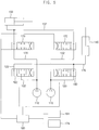
- FIG. 5 is a hydraulic circuit diagram illustrating a method of controlling a main control valve when a relatively great amount of the flux is supplied to the arm cylinder to increase a speed of the arm in accordance with example embodiments.
- the controller 180 may determine the increasing of the speed of the arm to close the second boom control spool 162.
- the first boom control spool 160 and the first arm control spool 170 may be opened.
- the second arm control spool 172 may be partially opened.
- a great part of the first flux generated from the first hydraulic pump 110 may be supplied to the boom cylinder 140 through the first boom line 120.
- a part of the first flux may be supplied to the arm cylinder 150 through the second arm line 132.
- the second flux generated from the second hydraulic pump 112 may not be supplied to the boom cylinder 140.
- the second flux may be supplied to the arm cylinder 150 through the first arm line 130.
- the boom joystick 164 may be partially handled compared than the arm joystick 174. After partially handling the boom joystick 164, when the boom joystick 164 may be handled in the decreasing direction with stopping of the arm joystick 174, the second boom control spool 162 may be closed. In contrast, the first boom control spool 160 and the first arm control spool 170 may be opened. The second arm control spool 172 may be partially opened.
- a total flux supplied to the arm cylinder 150 may be a sum of 100% of the second flux and the part of the first flux. Further, a total flux supplied to the boom cylinder 140 may be the great part of the first flux except for the part of the first flux passing through the second arm line 132. As a result, because the total flux supplied to the arm cylinder 150 may be higher than the total flux supplied to the boom cylinder 140, the speed of the arm may be increased and the speed of the boom may be decreased.
- the controller 180 may selectively open/close the first and second boom control spools 160 and 162 and the first and second arm control spools 170 and 172 in accordance with the handling directions of any one of the boom joystick 164 and the arm joystick 174 so that the pressure loss may be reduced.
- the first flux may be supplied to the boom cylinder through only the first boom control spool and the second flux may be supplied to the arm cylinder through only the first arm control spools.
- the second arm control spool and/or the second boom control spool may be selectively controlled by handling the boom joystick and/or the arm joystick. Therefore, the pressure loss caused by passing of the flux through the second boom control spool and the second arm control spool may be reduced.
Landscapes
- Engineering & Computer Science (AREA)
- General Engineering & Computer Science (AREA)
- Mining & Mineral Resources (AREA)
- Civil Engineering (AREA)
- Structural Engineering (AREA)
- Physics & Mathematics (AREA)
- Fluid Mechanics (AREA)
- Mechanical Engineering (AREA)
- Operation Control Of Excavators (AREA)
- Fluid-Pressure Circuits (AREA)
Applications Claiming Priority (1)
| Application Number | Priority Date | Filing Date | Title |
|---|---|---|---|
| KR1020160114233A KR102571079B1 (ko) | 2016-09-06 | 2016-09-06 | 굴삭기의 메인 컨트롤 밸브 제어 방법 및 이를 수행하기 위한 장치 |
Publications (2)
| Publication Number | Publication Date |
|---|---|
| EP3290597A1 true EP3290597A1 (fr) | 2018-03-07 |
| EP3290597B1 EP3290597B1 (fr) | 2023-04-12 |
Family
ID=59686830
Family Applications (1)
| Application Number | Title | Priority Date | Filing Date |
|---|---|---|---|
| EP17187385.4A Active EP3290597B1 (fr) | 2016-09-06 | 2017-08-23 | Procédé de commande d'une soupape de commande principale d'un excavateur et appareil à cet effet |
Country Status (4)
| Country | Link |
|---|---|
| US (1) | US10392779B2 (fr) |
| EP (1) | EP3290597B1 (fr) |
| KR (1) | KR102571079B1 (fr) |
| CN (1) | CN107794969B (fr) |
Cited By (1)
| Publication number | Priority date | Publication date | Assignee | Title |
|---|---|---|---|---|
| EP4202232A1 (fr) * | 2021-12-21 | 2023-06-28 | Danfoss Scotland Limited | Système hydraulique |
Families Citing this family (1)
| Publication number | Priority date | Publication date | Assignee | Title |
|---|---|---|---|---|
| WO2015099440A1 (fr) * | 2013-12-26 | 2015-07-02 | 두산인프라코어 주식회사 | Procédé et appareil de commande de la soupape de commande principale d'un engin de chantier |
Citations (5)
| Publication number | Priority date | Publication date | Assignee | Title |
|---|---|---|---|---|
| JPS58146629A (ja) * | 1982-02-24 | 1983-09-01 | Hitachi Constr Mach Co Ltd | 土木・建設機械の油圧回路 |
| JPH10176347A (ja) * | 1996-12-19 | 1998-06-30 | Sumitomo Constr Mach Co Ltd | 油圧ショベル制御回路 |
| EP1672127A2 (fr) * | 2004-12-16 | 2006-06-21 | Doosan Infracore Co., Ltd. | Commande hydraulique pour actionner en combinaison le bras avec le bras du godet d'une excavatrice |
| KR100923396B1 (ko) * | 2004-02-23 | 2009-10-23 | 현대중공업 주식회사 | 굴삭기 작업장치의 가변우선 시스템 |
| US20160252107A1 (en) * | 2013-10-31 | 2016-09-01 | Kawasaki Jukogyo Kabushiki Kaisha | Hydraulic excavator drive system |
Family Cites Families (7)
| Publication number | Priority date | Publication date | Assignee | Title |
|---|---|---|---|---|
| KR100348128B1 (ko) * | 1994-09-30 | 2002-11-22 | 볼보 컨스트럭션 이키프먼트 홀딩 스웨덴 에이비 | 가변우선기능을갖는콘트롤밸브 |
| JP2006029468A (ja) | 2004-07-16 | 2006-02-02 | Shin Caterpillar Mitsubishi Ltd | 流体圧制御装置 |
| JP4655795B2 (ja) * | 2005-07-15 | 2011-03-23 | コベルコ建機株式会社 | 油圧ショベルの油圧制御装置 |
| JP2009275769A (ja) * | 2008-05-13 | 2009-11-26 | Caterpillar Japan Ltd | 流体圧シリンダ制御回路 |
| JP5572586B2 (ja) * | 2011-05-19 | 2014-08-13 | 日立建機株式会社 | 作業機械の油圧駆動装置 |
| CN103857850A (zh) * | 2011-10-07 | 2014-06-11 | 沃尔沃建造设备有限公司 | 用于施工机械的优先控制系统 |
| US20130318959A1 (en) * | 2012-06-04 | 2013-12-05 | Caterpillar, Inc. | Hydraulic Circuits with Energy Conservation Features for Overrunning Load Conditions |
-
2016
- 2016-09-06 KR KR1020160114233A patent/KR102571079B1/ko active Active
-
2017
- 2017-08-22 US US15/683,107 patent/US10392779B2/en active Active
- 2017-08-23 EP EP17187385.4A patent/EP3290597B1/fr active Active
- 2017-09-05 CN CN201710792183.9A patent/CN107794969B/zh active Active
Patent Citations (5)
| Publication number | Priority date | Publication date | Assignee | Title |
|---|---|---|---|---|
| JPS58146629A (ja) * | 1982-02-24 | 1983-09-01 | Hitachi Constr Mach Co Ltd | 土木・建設機械の油圧回路 |
| JPH10176347A (ja) * | 1996-12-19 | 1998-06-30 | Sumitomo Constr Mach Co Ltd | 油圧ショベル制御回路 |
| KR100923396B1 (ko) * | 2004-02-23 | 2009-10-23 | 현대중공업 주식회사 | 굴삭기 작업장치의 가변우선 시스템 |
| EP1672127A2 (fr) * | 2004-12-16 | 2006-06-21 | Doosan Infracore Co., Ltd. | Commande hydraulique pour actionner en combinaison le bras avec le bras du godet d'une excavatrice |
| US20160252107A1 (en) * | 2013-10-31 | 2016-09-01 | Kawasaki Jukogyo Kabushiki Kaisha | Hydraulic excavator drive system |
Cited By (1)
| Publication number | Priority date | Publication date | Assignee | Title |
|---|---|---|---|---|
| EP4202232A1 (fr) * | 2021-12-21 | 2023-06-28 | Danfoss Scotland Limited | Système hydraulique |
Also Published As
| Publication number | Publication date |
|---|---|
| EP3290597B1 (fr) | 2023-04-12 |
| US20180066417A1 (en) | 2018-03-08 |
| CN107794969A (zh) | 2018-03-13 |
| CN107794969B (zh) | 2021-02-19 |
| KR20180027088A (ko) | 2018-03-14 |
| US10392779B2 (en) | 2019-08-27 |
| KR102571079B1 (ko) | 2023-09-06 |
Similar Documents
| Publication | Publication Date | Title |
|---|---|---|
| EP3283696B1 (fr) | Circuit hydraulique et engin de chantier | |
| US10519628B2 (en) | Control system for construction machinery and control method for construction machinery | |
| EP1895060A2 (fr) | Circuit hydraulique de direction | |
| US10577777B2 (en) | Control system for construction machinery | |
| KR101718835B1 (ko) | 건설기계의 유압제어밸브 | |
| KR20150122695A (ko) | 유압 장치의 합류 회로 | |
| EP1972726A1 (fr) | Circuit hydraulique pour empêcher la séparation de bac d'un appui de bac lors du voyage d'un équipement lourd | |
| EP3290597B1 (fr) | Procédé de commande d'une soupape de commande principale d'un excavateur et appareil à cet effet | |
| US9605693B2 (en) | Hydraulic pressure control device for swing motor for construction machinery | |
| CN203248431U (zh) | 一种卸荷阀及液压油缸回油背压卸荷装置和工程机械 | |
| CN107407299A (zh) | 建筑机械的油压驱动系统 | |
| US10167615B2 (en) | Control system for construction machinery and control method for construction machinery using the same | |
| US9618019B2 (en) | Hydraulic pressure control device for construction machinery | |
| EP1726723A2 (fr) | Engin de travaux publics | |
| EP3249114A1 (fr) | Soupape de commande pour équipement de construction | |
| US20170121943A1 (en) | Method and device for controlling main control valve of construction machinery | |
| US20030116010A1 (en) | Hydraulic valve control device for heavy construction equipment | |
| US9021796B2 (en) | Pipelayer | |
| US10273124B2 (en) | Rotation control system for material handling machines | |
| CN107313998A (zh) | 一种液压节能系统及正面吊 | |
| JP6381228B2 (ja) | 油圧駆動装置 | |
| JP3807581B2 (ja) | 斜板式可変容量ポンプを用いた油圧駆動回路 | |
| CN107477039B (zh) | 具有流量补偿功能的液压系统及工程机械 | |
| JP2005265049A (ja) | 作業機械の油圧駆動装置 | |
| CN108018896A (zh) | 挖掘机 |
Legal Events
| Date | Code | Title | Description |
|---|---|---|---|
| PUAI | Public reference made under article 153(3) epc to a published international application that has entered the european phase |
Free format text: ORIGINAL CODE: 0009012 |
|
| STAA | Information on the status of an ep patent application or granted ep patent |
Free format text: STATUS: THE APPLICATION HAS BEEN PUBLISHED |
|
| AK | Designated contracting states |
Kind code of ref document: A1 Designated state(s): AL AT BE BG CH CY CZ DE DK EE ES FI FR GB GR HR HU IE IS IT LI LT LU LV MC MK MT NL NO PL PT RO RS SE SI SK SM TR |
|
| AX | Request for extension of the european patent |
Extension state: BA ME |
|
| STAA | Information on the status of an ep patent application or granted ep patent |
Free format text: STATUS: REQUEST FOR EXAMINATION WAS MADE |
|
| 17P | Request for examination filed |
Effective date: 20180907 |
|
| RBV | Designated contracting states (corrected) |
Designated state(s): AL AT BE BG CH CY CZ DE DK EE ES FI FR GB GR HR HU IE IS IT LI LT LU LV MC MK MT NL NO PL PT RO RS SE SI SK SM TR |
|
| STAA | Information on the status of an ep patent application or granted ep patent |
Free format text: STATUS: EXAMINATION IS IN PROGRESS |
|
| 17Q | First examination report despatched |
Effective date: 20190305 |
|
| RAP3 | Party data changed (applicant data changed or rights of an application transferred) |
Owner name: HYUNDAI DOOSAN INFRACORE CO., LTD. |
|
| GRAP | Despatch of communication of intention to grant a patent |
Free format text: ORIGINAL CODE: EPIDOSNIGR1 |
|
| STAA | Information on the status of an ep patent application or granted ep patent |
Free format text: STATUS: GRANT OF PATENT IS INTENDED |
|
| INTG | Intention to grant announced |
Effective date: 20221102 |
|
| GRAS | Grant fee paid |
Free format text: ORIGINAL CODE: EPIDOSNIGR3 |
|
| GRAA | (expected) grant |
Free format text: ORIGINAL CODE: 0009210 |
|
| STAA | Information on the status of an ep patent application or granted ep patent |
Free format text: STATUS: THE PATENT HAS BEEN GRANTED |
|
| AK | Designated contracting states |
Kind code of ref document: B1 Designated state(s): AL AT BE BG CH CY CZ DE DK EE ES FI FR GB GR HR HU IE IS IT LI LT LU LV MC MK MT NL NO PL PT RO RS SE SI SK SM TR |
|
| REG | Reference to a national code |
Ref country code: GB Ref legal event code: FG4D |
|
| REG | Reference to a national code |
Ref country code: CH Ref legal event code: EP |
|
| REG | Reference to a national code |
Ref country code: DE Ref legal event code: R096 Ref document number: 602017067634 Country of ref document: DE |
|
| REG | Reference to a national code |
Ref country code: IE Ref legal event code: FG4D |
|
| REG | Reference to a national code |
Ref country code: AT Ref legal event code: REF Ref document number: 1559858 Country of ref document: AT Kind code of ref document: T Effective date: 20230515 |
|
| REG | Reference to a national code |
Ref country code: LT Ref legal event code: MG9D |
|
| REG | Reference to a national code |
Ref country code: NL Ref legal event code: MP Effective date: 20230412 |
|
| REG | Reference to a national code |
Ref country code: AT Ref legal event code: MK05 Ref document number: 1559858 Country of ref document: AT Kind code of ref document: T Effective date: 20230412 |
|
| PG25 | Lapsed in a contracting state [announced via postgrant information from national office to epo] |
Ref country code: NL Free format text: LAPSE BECAUSE OF FAILURE TO SUBMIT A TRANSLATION OF THE DESCRIPTION OR TO PAY THE FEE WITHIN THE PRESCRIBED TIME-LIMIT Effective date: 20230412 |
|
| PG25 | Lapsed in a contracting state [announced via postgrant information from national office to epo] |
Ref country code: SE Free format text: LAPSE BECAUSE OF FAILURE TO SUBMIT A TRANSLATION OF THE DESCRIPTION OR TO PAY THE FEE WITHIN THE PRESCRIBED TIME-LIMIT Effective date: 20230412 Ref country code: PT Free format text: LAPSE BECAUSE OF FAILURE TO SUBMIT A TRANSLATION OF THE DESCRIPTION OR TO PAY THE FEE WITHIN THE PRESCRIBED TIME-LIMIT Effective date: 20230814 Ref country code: NO Free format text: LAPSE BECAUSE OF FAILURE TO SUBMIT A TRANSLATION OF THE DESCRIPTION OR TO PAY THE FEE WITHIN THE PRESCRIBED TIME-LIMIT Effective date: 20230712 Ref country code: ES Free format text: LAPSE BECAUSE OF FAILURE TO SUBMIT A TRANSLATION OF THE DESCRIPTION OR TO PAY THE FEE WITHIN THE PRESCRIBED TIME-LIMIT Effective date: 20230412 Ref country code: AT Free format text: LAPSE BECAUSE OF FAILURE TO SUBMIT A TRANSLATION OF THE DESCRIPTION OR TO PAY THE FEE WITHIN THE PRESCRIBED TIME-LIMIT Effective date: 20230412 |
|
| PG25 | Lapsed in a contracting state [announced via postgrant information from national office to epo] |
Ref country code: RS Free format text: LAPSE BECAUSE OF FAILURE TO SUBMIT A TRANSLATION OF THE DESCRIPTION OR TO PAY THE FEE WITHIN THE PRESCRIBED TIME-LIMIT Effective date: 20230412 Ref country code: PL Free format text: LAPSE BECAUSE OF FAILURE TO SUBMIT A TRANSLATION OF THE DESCRIPTION OR TO PAY THE FEE WITHIN THE PRESCRIBED TIME-LIMIT Effective date: 20230412 Ref country code: LV Free format text: LAPSE BECAUSE OF FAILURE TO SUBMIT A TRANSLATION OF THE DESCRIPTION OR TO PAY THE FEE WITHIN THE PRESCRIBED TIME-LIMIT Effective date: 20230412 Ref country code: LT Free format text: LAPSE BECAUSE OF FAILURE TO SUBMIT A TRANSLATION OF THE DESCRIPTION OR TO PAY THE FEE WITHIN THE PRESCRIBED TIME-LIMIT Effective date: 20230412 Ref country code: IS Free format text: LAPSE BECAUSE OF FAILURE TO SUBMIT A TRANSLATION OF THE DESCRIPTION OR TO PAY THE FEE WITHIN THE PRESCRIBED TIME-LIMIT Effective date: 20230812 Ref country code: HR Free format text: LAPSE BECAUSE OF FAILURE TO SUBMIT A TRANSLATION OF THE DESCRIPTION OR TO PAY THE FEE WITHIN THE PRESCRIBED TIME-LIMIT Effective date: 20230412 Ref country code: GR Free format text: LAPSE BECAUSE OF FAILURE TO SUBMIT A TRANSLATION OF THE DESCRIPTION OR TO PAY THE FEE WITHIN THE PRESCRIBED TIME-LIMIT Effective date: 20230713 Ref country code: AL Free format text: LAPSE BECAUSE OF FAILURE TO SUBMIT A TRANSLATION OF THE DESCRIPTION OR TO PAY THE FEE WITHIN THE PRESCRIBED TIME-LIMIT Effective date: 20230412 |
|
| REG | Reference to a national code |
Ref country code: DE Ref legal event code: R081 Ref document number: 602017067634 Country of ref document: DE Owner name: HD HYUNDAI INFRACORE CO., LTD., KR Free format text: FORMER OWNER: HYUNDAI DOOSAN INFRACORE CO., LTD., INCHEON, KR |
|
| PG25 | Lapsed in a contracting state [announced via postgrant information from national office to epo] |
Ref country code: FI Free format text: LAPSE BECAUSE OF FAILURE TO SUBMIT A TRANSLATION OF THE DESCRIPTION OR TO PAY THE FEE WITHIN THE PRESCRIBED TIME-LIMIT Effective date: 20230412 |
|
| REG | Reference to a national code |
Ref country code: DE Ref legal event code: R097 Ref document number: 602017067634 Country of ref document: DE |
|
| PG25 | Lapsed in a contracting state [announced via postgrant information from national office to epo] |
Ref country code: SK Free format text: LAPSE BECAUSE OF FAILURE TO SUBMIT A TRANSLATION OF THE DESCRIPTION OR TO PAY THE FEE WITHIN THE PRESCRIBED TIME-LIMIT Effective date: 20230412 |
|
| PG25 | Lapsed in a contracting state [announced via postgrant information from national office to epo] |
Ref country code: SM Free format text: LAPSE BECAUSE OF FAILURE TO SUBMIT A TRANSLATION OF THE DESCRIPTION OR TO PAY THE FEE WITHIN THE PRESCRIBED TIME-LIMIT Effective date: 20230412 Ref country code: SK Free format text: LAPSE BECAUSE OF FAILURE TO SUBMIT A TRANSLATION OF THE DESCRIPTION OR TO PAY THE FEE WITHIN THE PRESCRIBED TIME-LIMIT Effective date: 20230412 Ref country code: RO Free format text: LAPSE BECAUSE OF FAILURE TO SUBMIT A TRANSLATION OF THE DESCRIPTION OR TO PAY THE FEE WITHIN THE PRESCRIBED TIME-LIMIT Effective date: 20230412 Ref country code: EE Free format text: LAPSE BECAUSE OF FAILURE TO SUBMIT A TRANSLATION OF THE DESCRIPTION OR TO PAY THE FEE WITHIN THE PRESCRIBED TIME-LIMIT Effective date: 20230412 Ref country code: DK Free format text: LAPSE BECAUSE OF FAILURE TO SUBMIT A TRANSLATION OF THE DESCRIPTION OR TO PAY THE FEE WITHIN THE PRESCRIBED TIME-LIMIT Effective date: 20230412 Ref country code: CZ Free format text: LAPSE BECAUSE OF FAILURE TO SUBMIT A TRANSLATION OF THE DESCRIPTION OR TO PAY THE FEE WITHIN THE PRESCRIBED TIME-LIMIT Effective date: 20230412 |
|
| PLBE | No opposition filed within time limit |
Free format text: ORIGINAL CODE: 0009261 |
|
| STAA | Information on the status of an ep patent application or granted ep patent |
Free format text: STATUS: NO OPPOSITION FILED WITHIN TIME LIMIT |
|
| PG25 | Lapsed in a contracting state [announced via postgrant information from national office to epo] |
Ref country code: MC Free format text: LAPSE BECAUSE OF FAILURE TO SUBMIT A TRANSLATION OF THE DESCRIPTION OR TO PAY THE FEE WITHIN THE PRESCRIBED TIME-LIMIT Effective date: 20230412 |
|
| 26N | No opposition filed |
Effective date: 20240115 |
|
| REG | Reference to a national code |
Ref country code: CH Ref legal event code: PL |
|
| PG25 | Lapsed in a contracting state [announced via postgrant information from national office to epo] |
Ref country code: MC Free format text: LAPSE BECAUSE OF FAILURE TO SUBMIT A TRANSLATION OF THE DESCRIPTION OR TO PAY THE FEE WITHIN THE PRESCRIBED TIME-LIMIT Effective date: 20230412 |
|
| PG25 | Lapsed in a contracting state [announced via postgrant information from national office to epo] |
Ref country code: LU Free format text: LAPSE BECAUSE OF NON-PAYMENT OF DUE FEES Effective date: 20230823 |
|
| PG25 | Lapsed in a contracting state [announced via postgrant information from national office to epo] |
Ref country code: LU Free format text: LAPSE BECAUSE OF NON-PAYMENT OF DUE FEES Effective date: 20230823 Ref country code: CH Free format text: LAPSE BECAUSE OF NON-PAYMENT OF DUE FEES Effective date: 20230831 |
|
| PG25 | Lapsed in a contracting state [announced via postgrant information from national office to epo] |
Ref country code: SI Free format text: LAPSE BECAUSE OF FAILURE TO SUBMIT A TRANSLATION OF THE DESCRIPTION OR TO PAY THE FEE WITHIN THE PRESCRIBED TIME-LIMIT Effective date: 20230412 |
|
| REG | Reference to a national code |
Ref country code: BE Ref legal event code: MM Effective date: 20230831 |
|
| REG | Reference to a national code |
Ref country code: IE Ref legal event code: MM4A |
|
| PG25 | Lapsed in a contracting state [announced via postgrant information from national office to epo] |
Ref country code: SI Free format text: LAPSE BECAUSE OF FAILURE TO SUBMIT A TRANSLATION OF THE DESCRIPTION OR TO PAY THE FEE WITHIN THE PRESCRIBED TIME-LIMIT Effective date: 20230412 Ref country code: IT Free format text: LAPSE BECAUSE OF FAILURE TO SUBMIT A TRANSLATION OF THE DESCRIPTION OR TO PAY THE FEE WITHIN THE PRESCRIBED TIME-LIMIT Effective date: 20230412 |
|
| PG25 | Lapsed in a contracting state [announced via postgrant information from national office to epo] |
Ref country code: IE Free format text: LAPSE BECAUSE OF NON-PAYMENT OF DUE FEES Effective date: 20230823 |
|
| PG25 | Lapsed in a contracting state [announced via postgrant information from national office to epo] |
Ref country code: IE Free format text: LAPSE BECAUSE OF NON-PAYMENT OF DUE FEES Effective date: 20230823 |
|
| PG25 | Lapsed in a contracting state [announced via postgrant information from national office to epo] |
Ref country code: BE Free format text: LAPSE BECAUSE OF NON-PAYMENT OF DUE FEES Effective date: 20230831 |
|
| PG25 | Lapsed in a contracting state [announced via postgrant information from national office to epo] |
Ref country code: BG Free format text: LAPSE BECAUSE OF FAILURE TO SUBMIT A TRANSLATION OF THE DESCRIPTION OR TO PAY THE FEE WITHIN THE PRESCRIBED TIME-LIMIT Effective date: 20230412 |
|
| PG25 | Lapsed in a contracting state [announced via postgrant information from national office to epo] |
Ref country code: BG Free format text: LAPSE BECAUSE OF FAILURE TO SUBMIT A TRANSLATION OF THE DESCRIPTION OR TO PAY THE FEE WITHIN THE PRESCRIBED TIME-LIMIT Effective date: 20230412 |
|
| PG25 | Lapsed in a contracting state [announced via postgrant information from national office to epo] |
Ref country code: CY Free format text: LAPSE BECAUSE OF FAILURE TO SUBMIT A TRANSLATION OF THE DESCRIPTION OR TO PAY THE FEE WITHIN THE PRESCRIBED TIME-LIMIT; INVALID AB INITIO Effective date: 20170823 |
|
| PG25 | Lapsed in a contracting state [announced via postgrant information from national office to epo] |
Ref country code: HU Free format text: LAPSE BECAUSE OF FAILURE TO SUBMIT A TRANSLATION OF THE DESCRIPTION OR TO PAY THE FEE WITHIN THE PRESCRIBED TIME-LIMIT; INVALID AB INITIO Effective date: 20170823 |
|
| PGFP | Annual fee paid to national office [announced via postgrant information from national office to epo] |
Ref country code: DE Payment date: 20250702 Year of fee payment: 9 |
|
| PGFP | Annual fee paid to national office [announced via postgrant information from national office to epo] |
Ref country code: GB Payment date: 20250703 Year of fee payment: 9 |
|
| PGFP | Annual fee paid to national office [announced via postgrant information from national office to epo] |
Ref country code: FR Payment date: 20250703 Year of fee payment: 9 |
|
| PG25 | Lapsed in a contracting state [announced via postgrant information from national office to epo] |
Ref country code: TR Free format text: LAPSE BECAUSE OF FAILURE TO SUBMIT A TRANSLATION OF THE DESCRIPTION OR TO PAY THE FEE WITHIN THE PRESCRIBED TIME-LIMIT Effective date: 20230412 |