EP3290555A1 - Needle for forming stitches on a weft or warp knitting machine, weft or warp knitting machine with a plurality of such needles and method for producing such a needle - Google Patents
Needle for forming stitches on a weft or warp knitting machine, weft or warp knitting machine with a plurality of such needles and method for producing such a needle Download PDFInfo
- Publication number
- EP3290555A1 EP3290555A1 EP16001924.6A EP16001924A EP3290555A1 EP 3290555 A1 EP3290555 A1 EP 3290555A1 EP 16001924 A EP16001924 A EP 16001924A EP 3290555 A1 EP3290555 A1 EP 3290555A1
- Authority
- EP
- European Patent Office
- Prior art keywords
- needle
- hook
- needles
- upper portion
- knitting machine
- Prior art date
- Legal status (The legal status is an assumption and is not a legal conclusion. Google has not performed a legal analysis and makes no representation as to the accuracy of the status listed.)
- Withdrawn
Links
- 238000009940 knitting Methods 0.000 title claims abstract description 101
- 238000004519 manufacturing process Methods 0.000 title claims abstract description 20
- 230000005540 biological transmission Effects 0.000 claims abstract description 49
- 238000012546 transfer Methods 0.000 claims description 74
- 238000003466 welding Methods 0.000 claims description 16
- 238000000034 method Methods 0.000 claims description 12
- 210000002105 tongue Anatomy 0.000 description 35
- 229910000831 Steel Inorganic materials 0.000 description 26
- 239000010959 steel Substances 0.000 description 26
- 238000005516 engineering process Methods 0.000 description 25
- 230000015572 biosynthetic process Effects 0.000 description 14
- 238000013461 design Methods 0.000 description 13
- BASFCYQUMIYNBI-UHFFFAOYSA-N platinum Chemical group [Pt] BASFCYQUMIYNBI-UHFFFAOYSA-N 0.000 description 10
- 230000008901 benefit Effects 0.000 description 9
- 238000011161 development Methods 0.000 description 9
- 230000018109 developmental process Effects 0.000 description 9
- 230000000694 effects Effects 0.000 description 9
- 210000000481 breast Anatomy 0.000 description 8
- 230000008569 process Effects 0.000 description 8
- 238000007747 plating Methods 0.000 description 7
- 230000009471 action Effects 0.000 description 5
- 238000010276 construction Methods 0.000 description 5
- 229910000639 Spring steel Inorganic materials 0.000 description 4
- 239000002245 particle Substances 0.000 description 4
- 239000011295 pitch Substances 0.000 description 4
- 235000014676 Phragmites communis Nutrition 0.000 description 3
- 238000010586 diagram Methods 0.000 description 3
- 239000004744 fabric Substances 0.000 description 3
- 230000000717 retained effect Effects 0.000 description 3
- 238000003860 storage Methods 0.000 description 3
- 238000013459 approach Methods 0.000 description 2
- 230000000295 complement effect Effects 0.000 description 2
- 239000000463 material Substances 0.000 description 2
- 239000004753 textile Substances 0.000 description 2
- 229920000049 Carbon (fiber) Polymers 0.000 description 1
- 229920001131 Pulp (paper) Polymers 0.000 description 1
- 241000673677 Viburnum lantana Species 0.000 description 1
- 230000001154 acute effect Effects 0.000 description 1
- 238000004026 adhesive bonding Methods 0.000 description 1
- 230000003466 anti-cipated effect Effects 0.000 description 1
- 239000004917 carbon fiber Substances 0.000 description 1
- 210000000038 chest Anatomy 0.000 description 1
- 230000015271 coagulation Effects 0.000 description 1
- 238000005345 coagulation Methods 0.000 description 1
- 230000001419 dependent effect Effects 0.000 description 1
- 238000000151 deposition Methods 0.000 description 1
- 230000008021 deposition Effects 0.000 description 1
- 238000001514 detection method Methods 0.000 description 1
- 238000010438 heat treatment Methods 0.000 description 1
- 230000003993 interaction Effects 0.000 description 1
- 229910052751 metal Inorganic materials 0.000 description 1
- 239000002184 metal Substances 0.000 description 1
- 238000005555 metalworking Methods 0.000 description 1
- VNWKTOKETHGBQD-UHFFFAOYSA-N methane Chemical compound C VNWKTOKETHGBQD-UHFFFAOYSA-N 0.000 description 1
- 238000000059 patterning Methods 0.000 description 1
- 230000000149 penetrating effect Effects 0.000 description 1
- 229910052697 platinum Inorganic materials 0.000 description 1
- 238000011084 recovery Methods 0.000 description 1
- 230000009467 reduction Effects 0.000 description 1
- 230000002441 reversible effect Effects 0.000 description 1
- 239000007787 solid Substances 0.000 description 1
- 230000000087 stabilizing effect Effects 0.000 description 1
- 230000000638 stimulation Effects 0.000 description 1
- 239000013589 supplement Substances 0.000 description 1
- 230000001360 synchronised effect Effects 0.000 description 1
- 238000009732 tufting Methods 0.000 description 1
- 229960005486 vaccine Drugs 0.000 description 1
- 239000002023 wood Substances 0.000 description 1
Images


Classifications
-
- D—TEXTILES; PAPER
- D04—BRAIDING; LACE-MAKING; KNITTING; TRIMMINGS; NON-WOVEN FABRICS
- D04B—KNITTING
- D04B35/00—Details of, or auxiliary devices incorporated in, knitting machines, not otherwise provided for
- D04B35/02—Knitting tools or instruments not provided for in group D04B15/00 or D04B27/00
- D04B35/06—Sliding-tongue needles
-
- D—TEXTILES; PAPER
- D04—BRAIDING; LACE-MAKING; KNITTING; TRIMMINGS; NON-WOVEN FABRICS
- D04B—KNITTING
- D04B9/00—Circular knitting machines with independently-movable needles
- D04B9/02—Circular knitting machines with independently-movable needles with one set of needles
Definitions
- the present invention relates to a needle for knitting a knitting or warp knitting machine, a knitting or warp knitting machine having a plurality of such needles, and a method of manufacturing such a needle.
- the invention is a further development of the German patent no. 10 2007 039 973 of 23.08.2007, which realizes an advantageous control of the opening and closing movement of a longitudinally guided tongue member without the need for slide needles second castle track.
- the patent was intended to avoid the disadvantages of the latch needle with ever-finer needle pitches, ie a needle technology without pivoting tongues should be pointed out.
- the latch needle which prevailed dominant for the mass production of knitted fabrics.
- the prerequisite for this was hardenable steel, which could only be produced in the required quality from the middle of the 19th century.
- the pivoting-tongue needle is designed as a ready-to-install functional unit that can be easily inserted and replaced by the operator in the machine. With increasing increases in rotational speeds in circular knitting machines and simultaneous multiplication of the knitting systems, however, the described advantage proves to be a weak point for production safety.
- the advantages of the reed needles technology as a functional unit with the advantages of the needles and at the same time to avoid the disadvantage of having to use an extra controlled complementary element in user-friendly size in the machine is in the DE 10 2007 039 973 .
- a vibrating-needle technology is provided in which the long shaft of the slider element is transformed into a mini-board member reciprocating within the needle. This is moved in phases along with the needle and on the other hand by the Machine controlled phased stopped. From the point of view of implementation, the longitudinal guide is always more complex than the fulcrum bearing of a component.
- the board should have a leadership approach and be secured with tongue and groove laterally against falling out of the needle shaft smoothly, which limits the fineness of execution in addition to these difficulties in mass production.
- the problematic longitudinal storage with the smallest size is simplified in that between the vibrating member and the needle body, a central connecting bracket is provided which ensures both the relative movement of the oscillating member to Nadelgroper and its lateral guidance and on the sliding surface in the needle. In this way, analogous to the up and zuschwenkenden tongue in the needle reciprocating mini-board member realized with the important difference, not by the thread, but to be controlled by the machine.
- both types the phased arrest of the transfer member during the stitch formation is done by a holding balcony of the issued patent within the needle lock on a stop tooth of the transfer member acts.
- both types would be possible on a much broader basis if no additional elements were required within the lock systems.
- the machine designs would then be possible on those of the previous latch needle. This would also allow the implementation of the process for double-sided knits.
- the inwardly tapered knitting systems for the dial exclude other components.
- the object of the invention characterized in claim 1 is to provide a needle for stitching on a knitting or warp knitting machine, which has a simple, stable and compact construction and can be produced in a simple manner. Moreover, the invention provides a knitting or warp knitting machine with a plurality of such needles according to claim 11 and a method of manufacturing such a needle according to claim 17. Preferred embodiments of the invention follow from the dependent claims.
- the needle for knitting on a knitting or warp knitting machine comprises a base body, a needle hook and a transmission member or tongue member which is movable in the longitudinal direction of the base body relative to the base body and the needle hook and is adapted to the needle hook by a relative movement to the base body to close and open.
- the needle further comprises a connector which engages around the transmission member or tongue member along at least a portion of the length of the transmission member or tongue member such that the relative movement of the transmission member or tongue member is guided to the body by the connector, the connector engaging with an upper portion of the body Basic body is connected.
- the connecting element may be a U-shaped connecting element.
- the transmission member or tongue member may be received in the recess of the U-shaped connecting element.
- the U-shape of the connecting element engages around the transmission member.
- the connecting element may be formed as a U-shaped bracket.
- the needle according to the invention makes it possible to effect the control function for the opening and closing movement of a transmission member outside the needle movement system. Another advantage is to be able to influence the positioning of a plating thread in the needle hook.
- the structure of the functional unit needle with longitudinally guided transmission member is compact, so that no dirt particles can penetrate within the system. Since the connecting member is provided so as to be connected to an upper portion of the main body, the needle can be easily manufactured. Moreover, the needle has a simple and stable construction.
- the longitudinal movement of the transfer member or tongue member in the needle may occur during needle movement by phase-limited stopping on an engagement member, such as a cut or bump, of the transfer member or tongue member outside the knitting systems by means of holding blades, for example, lined up around a needle cylinder.
- the front of a transfer finger of the transfer member or tongue member on the needle hook by means of a notched projection on its front section.
- the transfer finger height is advantageously larger and more stable due to a reduction, and its underside can also be formed for the exact positioning of a plating thread.
- plating forms the basis for a large number of pattern types. In this case, two different threads must be supplied separately to the needles and cover a cover thread as the basic thread. This requires a precise positioning of the threads in the needle, which must be preserved in the stitch formation. In trials of various users with the known needles has Surprisingly, it turns out that safety is less here than with tongue needles.
- the design possibility of the widened transfer finger favors the fulfillment of the high demand uniform positioning of the separately supplied threads in the needle hook.
- connection of the invention of the connecting element with the upper portion of the body allows easily replaceable needle elements, which types of knitting arise that extends the scope for double-surface generating circular knitting machines to flat knitting machines in designs from coarse to fine.
- the transfer member or tongue member of the needle becomes the rod-shaped profile of a compact design which together with the main body or needle body forms a prismatic body without interruptions or recesses which completely fills the needle channel and thereby prevents the ingress and seizing of dirt particles.
- the stop tooth on the tongue member within the knitting system and the corresponding holding balconies can be replaced by measures outside the knitting systems. Instead of the stop tooth, at the top, in particular at the top, a narrow holding recess or alternatively a bump may be provided in a shank of the transfer member or tongue member, in which during the downward movement of the needle to close the needle hook an engaging unit of the knitting or warp knitting machine, such as the projection one Blade section outside the castle, engages.
- blade sections can be supplemented at the top of the lock to form a ring around the needle cylinder.
- These are simple platinum parts that line up in a stop recess on the upper side of the lock and can be fixed there using familiar technology, including gluing.
- a second section projection can be used, which stops the transmission finger on the transmission member or tongue member in the needle-down movement.
- the arrangement allows the simplest realization of the desired relative movement of the transmission member or tongue member to the needle body without additional controls. In this way, completely new machine conceptions can be made possible.
- the transmission member or tongue member becomes easy to manufacture component and can then placed both with device handling and automatable placed over the needle body, above, in particular perpendicular, the connecting element, such as a particular U-shaped connecting bracket inserted and, for example, beyond the tongue member base protruding leg be fastened in fixing recesses on the needle shaft.
- the stitch-forming function corresponds to that described in the starting patent.
- the invention is basically applicable to all machine variants and is particularly advantageous for the finest pitches and lowest mesh heights with the aim of solid mesh fabrics.
- the main body has the upper portion immediately adjacent to the needle hook in the longitudinal direction of the main body, a central portion immediately adjacent to the upper portion in the longitudinal direction of the main body, and a needle foot extending longitudinally of the main body to the middle section adjoins.
- the needle foot can connect directly to the middle section in the longitudinal direction of the main body.
- the upper portion may have a smaller lateral extent perpendicular to the longitudinal direction of the main body than the middle portion, so that a step is formed between the upper portion and the middle portion.
- the connecting element may be arranged completely above the step in the direction of the needle foot on the needle hook.
- the central portion may have a smaller lateral extent perpendicular to the longitudinal direction of the main body than the needle butt.
- the step may extend perpendicular to the longitudinal direction of the base body.
- the relative movement of the transfer member to the main body may be completely above the step, i. above the step in the direction of the needle foot on the needle hook, done.
- the needle according to the invention may be arranged so that the step forms a stop surface for a lower end surface of the transmission member. In this case, the relative movement of the transfer member to the body downward, ie in the direction of the needle foot, are limited by the step.
- the connecting element may be connected to the upper portion of the base body by a welded connection, in particular a laser welding connection.
- a welded connection in particular a laser welding connection.
- the laser welding connection can be made by conventional laser welding technology. Welding, especially laser welding, leaves unambiguously identifiable traces on the finished needle that enable one to distinguish such a needle from needles made by other methods.
- the welded connection in particular the laser welding connection, can be in the form of a weld or a spot weld, for example.
- the transfer member may include an engagement member for engagement with an engagement unit of the knitting or warp knitting machine.
- the engagement element can be a recess or a projection, in particular a bump, which runs in the direction perpendicular to the longitudinal direction of the base body.
- the needle hook may be formed integrally with the base body. In this case, the body has the needle hook.
- the needle hook can be integrally formed, in particular in one piece, with the connecting element.
- the needle hook may have two halves, wherein the two halves may be separated from one another at least in regions by a gap. The two halves can be completely separated by the gap.
- the two halves of the needle hook may be formed so that a needle curvature of each half extends in a plane parallel to the plane in which a needle curvature of the needle hook extends.
- the gap may lie in a plane or extend in a plane which is parallel to the plane in which the needle curvature of the needle hook extends.
- the transfer member may have at an upper end thereof in the direction of the needle butt on the needle hook to a transfer finger, which is adapted to close and open the needle hook by the relative movement of the transfer member to the base body.
- the transmission finger may have an upper portion and a lower portion which adjoins the upper portion directly in the longitudinal direction of the main body.
- the upper portion of the transfer finger may have a smaller lateral extent perpendicular to the longitudinal direction of the main body than the lower portion of the transfer finger, so that a step is formed between the upper portion and the lower portion.
- the needle may be arranged so that the step of the transfer finger forms a stop surface for a lower end surface of the needle hook, so that the relative movement of the transfer member to the main body upwards, ie in the direction of the needle hook, is limited by the step.
- a knitting or warp knitting machine comprising a plurality of needles according to the invention.
- the knitting or warp knitting machine according to the invention provides the advantageous effects that have already been set out above for the needle according to the invention.
- the plurality of needles may be sequentially arranged in the knitting or warp knitting machine.
- the knitting or warp knitting machine may comprise only needles according to the invention.
- the knitting or warp knitting machine may further comprise an engaging unit for engaging with engaging elements of the transfer members of the needles.
- the engagement unit may include a plurality of protrusions and recesses alternately arranged along the direction along which the plural needles are successively arranged in the knitting or warp knitting machine.
- the projections and recesses may each extend in a direction which is substantially perpendicular to the arrangement direction of the needles and / or substantially perpendicular to the longitudinal direction of the main body of the needles.
- the engagement unit may comprise a holding rocker.
- the engagement unit may be a holding rocker.
- the knitting or warp knitting machine may further comprise a rotatable and a knock-off having needle cylinder, wherein the plurality of needles are arranged in the needle cylinder.
- the knitting or warp knitting machine may further comprise from the needle back forth in between the needles present needle gaps engaging holding elements, in particular in the form of a spring ring spiral, which form a gap to the tee edge, the newly formed mesh slips through and stops the stitches at the tee edge on further pushing the needles.
- the holding elements in particular the spring ring spiral, can be rotatably mounted, so that the holding elements, in particular the spring ring spiral, can be rotated together with the needle cylinder.
- the holding elements, in particular the spring-ring spiral can be rotated by their engagement in the needle gaps together with the needle cylinder.
- a method of manufacturing the needle of the present invention comprising the steps of: providing the body, the needle hook, the transmission member, and the connector, and connecting the connector to the upper portion of the body so that Connecting element surrounds the transmission member at least along part of the length of the transmission member.
- the connecting element can be connected to the upper portion of the base body by welding, in particular laser welding.
- connection of the connecting element to the upper portion of the base body can be carried out by conventional laser welding technology.
- the welding process in particular the laser welding process, can be carried out in such a way that the welded connection, in particular the laser welding connection, is present, for example in the form of a weld seam or a spot weld.
- FIGS. 1 to 50 Embodiments of the invention will be described with reference to FIGS FIGS. 1 to 50 explained. These are, unless otherwise indicated, all carried out on an enlarged scale about 5: 1.
- FIGS. 1 to 17 are illustrations of the stitch formation of single-circular knitting machines. For their practicality boards are not shown between the needles between the needles in a sinker ring around the needle cylinder is provided which retains the hanging hook in the last stitch when the needle abuts the tee and the newly forming loop passes over the hook. In this version, little insight into the stitch formation is possible because everything is zu correlate here. In contrast, the execution of the FIGS. 18 to 20 a clear design of a single knitting machine without blanks. Instead of this, the turns of a spring-ring spiral engage with a pitch corresponding to the pitch above the knock-off edge of the needle cylinder from the back of the needle into the intermediate spaces of the needles.
- the smooth bearing point (ball bearing) for receiving horizontal guide segments for fixing the spring ring spiral is provided on a downwardly extending journal, which in Outer diameter is so large that the turns engage in the interstices of the needles and so hold down the stitches in the needle upward movement.
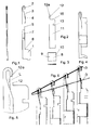
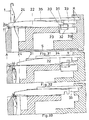
- Fig. 1 shows in a side view and plan view of the needle body or base body 1, which has the needle-specific features needle hook 2, needle face 3, needle slot 4. Behind this is the offset 5, which is up to the end stop 6 for the transmission member 11 (FIG. Fig.2 ) in its rear position extends.
- the needle hook 2 includes a zipper at the top for receiving the transfer finger 12.
- Lateral fixing recesses 7 are for mounting and fixing a connecting bracket 8 (FIG. Figure 3 ) is provided with its attachment zone of the open legs 9.
- the Fig. 2 is also a side view of the transfer member 11, which forms a prismatic body as a flat component without depositions to the end face 15 which completely fills together with the needle body 1 within the needle channel and merges with the transfer 12 at the front of the transfer finger 12a. In the vicinity of the end face 15 of the retaining recess 13 is provided.
- Fig. 3 is a representation of a side view and the top view of the U-shaped connecting bracket 8. This has a head 10 and the attachment zone of the open legs 9. In addition, shows Fig. 3 schematically a welding point through which the connecting bracket 8 is connected to the upper portion of the main body or needle body 1.
- FIG. 4 is shown in a side view of the fully assembled compact functional unit Lssenszeptnadel.
- the transfer member 11 is thereby in the front closed position of the needle hook 2 by the transfer finger 12 due to the abutment of the offset 12a at the front edge of the needle hook 2.
- Penetrating thread particles at the rear end of the transmission member 11 can not build up. They are pushed at the opening of the needle hook to the stop 6, where they pass through its bevel again from the needle channel.
- the Fig. 5 shows the front part of the Fig. 4 in 20x magnification.
- the transfer finger 12 widened around the step 12a supports on its lower side the separate positioning of the plating yarn from the main yarn for the knitting operation of the plating.
- the bottom may have a Leitkufe L, which directs the Plattierfaden to the bottom in the hook 2 and the transfer finger 12 leads exactly to the hook center.
- Fig. 6 is the schematic representation of the thread inlet during the plating process in 4 phases.
- Plating or covering forms the basis for a large number of pattern types.
- the two different threads must be supplied to the needles exactly separated from two thread guides.
- the cover yarn D is fed at a more acute angle relative to the background yarn G and passes during the relative movement of the needle hook 2 to the transfer finger 12 on the underside of which ie closer to the needle shank and to the knock-off edge as the introduced in the needle hook 2 ground yarn G.
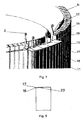
- the Fig. 7 is the graphically enlarged 3D principle representation for the arrangement of the functional parts for opening and closing movement of the transfer finger 12 with respect to the needle hook 2.
- the needle cylinder N contains the top 16 in the channel side walls of the piercing 16 before the steel band section 17 and in the cycle of the needle positions the projections 18th , once in the retaining recess 13, the other times on the end face 15 of the transmission member 11 are in operative connection. For better understanding, the channel side walls are hidden.
- the direction of rotation of the cylinder is clockwise.
- the steel belt section 17 is an example of an engagement unit of the knitting or warp knitting machine.
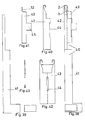
- the Fig. 8 is a schematic diagram of the arrangement of a steel band section 17 at the top of the lock system in a stop recess 20.
- a steel band cover 25 may be attached unusually glued, so that there is a gap in which the steel band section 17 is held under tension.
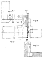
- Fig. 11 shows the state in which by further return movement of the needle 1 of Fig. 10 to Fig. 11 the holding recess 13 was located above the first gap of the steel belt section 17, so that the needle 1 moved together with the forwardmost transfer member 11 in the Kulier ein. During this process, the old mesh is thrown off the transfer finger 12, so that now a new loop in the needle hook 2 depends.
- the second retaining projection 18 of the steel belt section 17 is already above the end face 15 on the transmission member 11th
- Fig. 12 shows the state in which by the forward movement of the needle 1 of Fig. 11 to Fig. 12 the transfer member 11 was stopped with its end face 15 from the second retaining projection 18 and the transfer finger 12 the needle hook 2 opened, ie this gets back into the needle breast 3.
- the face 15 is already at the beginning of the second gap of the steel belt section 17.
- the new mesh passes from the needle hook 2 to the breast rise 3.
- the groove 16 in the channel side wall of the needle cylinder is visible.
- Fig. 13 shows the final phase, ie the state of Fig. 12 to Fig. 13 , in which no retaining projection 18 of the steel belt section 17 is present, ie needle 1 and transmission member 11 come together in the Austriebswolf.
- the retaining recess 13 runs in the next knitting system again in the retaining projection 18 of the steel belt section 17 a.
- FIGS. 14 to 17 illustrate the two different arrangements of the steel belt sections 17 on the lock system, the holding projections 18 project once from the inner surface and the other times are flush with this. This also causes differences in front of the transfer member 11 and the needle cylinder N.
- the Fig. 15 above shows in a section of the cylinder and the upper lock area the engagement of the lock inner surface protruding holding projections 18 in the recess 16 of the channel webs of the needle cylinder N.
- the bottom view is the top view of the cutout with a view of the needle channels and the detection of holding projections 18, which protrude into the invisible puncture 16 of the side walls.
- Fig. 16 the transfer member 11 instead of the holding incision 13 on a bump 14, which in the left Fig. Below and in the right Fig. above a Active connection with the holding projections 18 on the steel strip section 17 is received.
- the retaining projections 18 do not protrude beyond the inner surface of the needle lock.
- a recess 19 is provided below the retaining projections 18 in the needle lock.
- the Fig. 17 Above shows in a section of the cylinder and the upper lock area corresponding to the needle cylinder outer diameter retaining projections 18 on the recess 19 on the needle lock for the forward and backward movement of the hump 14 on the transfer member 11 and the bottom in plan view, the visible holding projections 18 of the steel belt section 17th
- the Fig. 19 is the top view of Fig. 18 into a guide segment 56 for the spring ring spiral 55 with the representation of the engagement of some turns of the spring ring spiral 55 in the needle gaps.
- Fig. 20 is a section through the needle cylinder N after the withdrawal of the needle 1, in which the bump 14 closes by engaging the retaining projection 18 of the steel belt section 17, the needle hook, as shown in Fig. 18 is apparent.
- FIGS. 21 to 26 are schematic representations of the stitch formation of a single circular knitting machine using conventional boards and based on the in Fig. 20 shown new machine concept in one Section through the needle channel and the attached circuit board ring.
- Fig. 21 shows the position of the board P to the needle 1 at the beginning of the thread inlet.
- the last stitch is located in the inclusion throat of the board P.
- the board P has a guide nose 29 for the thread inlet in the needle hook 2.
- the Fig. 24 shows the Kulier ein the needle 1 with simultaneous ejection of the old stitch from the needle hook 2. In this case, the board P goes back completely, so as not to hinder the formation of the new stitch in the needle hook 2.
- the needle 1 has already advanced a bit and the board P assumed its front position, so that after further forward movement of the needle 1 for Fig. 21 located in the needle hook 2 new mesh is retained by the Leitnase 29 of the board P and passes to the needle breast 3.
- the Fig. 26 shows on the left the view from the front on the thread guide, like the thread afterwards as a result of the thread feed forms an angle in the Kul réelle and right as in the side view of the needle hook 2, by the Leitnase 29 on the board P, the thread is introduced into the interior of the needle hook 2.
- the Fig. 27 is a sectional view of the 3D representation of the needle cylinder N with the pressed-on circuit board ring 22 as an assembly unit that allows a new machine design. Below the sinker ring 23 is the recess 16 in the side walls of the needle channels.
- the Fig. 28 is in 3D representation the front view of the Fig. 27 , It can be seen how the board slots are arranged between the needle channels.
- the embodiment of the sinker ring 22 with carbon fiber material may be advantageous.
- the Fig. 29 is the 3D representation of an advantageous single-circular knitting machine with individually controlled boards P through the disposed above the sinker ring 23 control cam 27, which can be adjusted radially by means of a control screw 25.
- Fig. 30 is the 3D principle representation of a RR circular knitting machine with needle technology according to the invention.
- a dial R is provided, in which so-called Rippnadeln are provided on the gap to the cylinder needles. In this way, double-surface knits can be produced.
- the execution of the transmission member 11 is here after the Fig. 16 shown with hump 14.
- FIGS. 31 to 37 For the sake of completeness, the use of features of the invention is also apparent for latch needles. In this case, the larger needle path in the mesh formation in the eye, which affects less systems. Instead of the usual boards, which gives an insight into the stitch formation there are mesh holders / sliders here that make an accessible machine concept possible.
- the Fig. 31 Fig. 3 is a view of the side surface of a mesh slider 22 which is in its forward position through the forward slide 33 of the previous system. When pushing the needle 1, the retaining lug 24 formed by the limited upward entrainment by means of the loop stitch to the cylinder upper edge a gap Sp, so that the old mesh could slip through.
- the illustrated Vor section 33 is still the previous system, that is no longer effectively present, so that upon further rotation the spring steel 31 in action in the recovery section 30 in action until the mesh sliding element 22 in his in the Fig. 32 shown vomateend ein passes.
- the Federstahlleitband 31 on the upper side surface has a bulge 34 under this effect, the retaining lug 24 is pressed by means of the rocking movement of the shaft bottom on the tee edge A.
- no spring steel band housing 32 now occurs in action, as in the Fig. 33 is shown.
- FIGS. 34 and 35 are additional explanations of the type after the FIGS. 31 to 33 for the Segment horraufsatz 29.
- This contains the housing 32 with Federstahlleitband 31 and the recording of Vor presentgleitsay 33.
- the housing 32 is in the Fig. 34 in the central elevation section of the control block 29 shown as a side view.
- a mesh slider / holder 22 inserted into the slit ring 23 is shown as a side view in FIG Fig. 34 pictured at the rear end in its rear position.
- the gap Sp to the Abschlagkante A Fig. 31 ).
- the Federstahlleitband 31 is engaged in the remindholausschnitt 30 of the mesh slider / holder 22, which is due to the upward movement of the retaining lug 24 in the lower tilted position.
- Fig. 35 is the top view of the right-handed slot ring 23 in which the rear portion of a mesh slider / holder 22 is inserted in the slide slot 21 in the reverse position and the view of the fixed segment control cap 29 without the cover rail 35, so that in the upper half of the housing 32 and in the lower half of the forward sliding plate 33 is recognisably mounted in the segment control attachment 29.
- a recess 36 in the housing 32 results in two side bars whose slots 37 correspond to the return path of the mesh slide / holder 22 with distances to the axis of rotation.
- the illustration also shows that the spring steel guide band 31 protrudes beyond the housing 32 side webs in the region of the forward sliding plate 33 and there the spring steel 31 has a bulge 34, under this effect, the mesh slide / holder 22 presses with its retaining lug 24 on the tee edge A ( Fig. 32 ).
- Fig. 36 is the right partial top view of the side surface of the Federstahlleitbandes 31, in the right end of the bulge 34 is recognizable on the upper edge.
- Fig. 37 shows how in a recess of the tee A, a spring wire ring 40 is received, which is inserted in a groove on the front side of the cylinder Z, wherein the seat fixation is ensured by phased contact pressure from the retaining lugs 24.
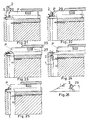
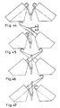
- FIGS. 38 to 43 An embodiment of a needle according to this new technology is disclosed in U.S. Pat FIGS. 38 to 43 shown.
- the FIGS. 44 to 47 and 48 to 50 show two examples of applications of such new needles.
- the Fig. 38 is the representation of this overall concept knitting or knitting needle 40 consisting of needle body 41 and mesh section 42, in which the transmission tongue 43 is longitudinally movably contained.
- the mesh section 42 is an embodiment of the fastener according to the present invention.
- the flat sides of the U-shaped mesh section 42 go forward in the split needle breast 3 and the two-part needle hook 2 over.
- the needle body 41 can either be offset on both sides in front, so that the mesh section 42 introduced above is laterally flat, or as shown, are placed on the shaft of the needle body 41 adapted to the interior of the U-shaped mesh section 42. It is then expedient to provide a small U-bracket in the region of the foot in order to stabilize the weaker shaft of the needle body 41 as it moves in the needle channel.
- Fig. 39 is the representation of the needle body 41 and the small stabilizing U-bracket for the needle foot for movement in the needle channel of the textile machine, wherein just in the needle body 41, a recess for receiving the transmission tongue 43 is provided.
- Fig. 40 is the side view of the U-shaped bracket of the mesh section 42, in which the two-sided course of the flat sides merges forward into the chest and hook halves (polished steel surfaces instead of milled surfaces).
- the lower edges are welded to the lower edge of the needle body 41 by laser technology. In this case, in particular a laser weld seam can be formed for connection.
- Fig. 41 is the side view of the transmission tongue 43, which has just the transmission finger 12 and the shaft below the retaining tooth 45.
- Fig. 42 is the view of the development of only flat board of the U-shaped bracket of the mesh section 42 in Fig. 40 with stop breakthrough 44 for the holding tooth 45. From there above and below, a narrow zone of the central axis is soft annealed by laser technology, so that the U-bend to the mesh section 42 can be performed.
- the stop breakthrough 44 may be formed so that it the relative movement of the transmission member or the transmission tongue 43 to the base body upwards or forwards, ie in the direction of the needle hook, and / or down or back, ie in the direction of the needle foot , limited. This limitation is achieved by an interaction of the Antschticians 44 with the holding tooth 45th
- Fig. 43 Below shows the view from the front of the split needle head, which was welded in the base area and in the area of the transfer finger 12 a this adapted having a bent bed and Fig. 43 Above shows the view of the split side surfaces of the mesh section 42, which are welded together unifying front and just, not visible, form the receiving bed for the transfer finger 12.
- the needle hook thus has two halves, the two halves being separated by a gap.
- FIGS. 44 to 47 is the mesh transfer to a needle of the other needle bed of a flat knitting machine, without having to make complicated effort on the needle, can be seen.
- the two needle beds are brought to each other in the alignment position of the needle channels and in the Fig. 44 the donor and the accepting needle are shown in the starting position, each with a loop in the needle hook.
- Figures 48 to 50 show the representation of the stitch forming center of the significant pulp production of a warp knitting machine.
- the needles are not housed individually movable in needle beds, but firmly clamped in so-called needle bar in a certain division. To stitch, all needles move together. Patterns that are based on the basic functions of knitting, non-knitting and tufting are not possible here.
- Parallel to the needle bars, the needle closing elements are provided in a second bar system in the machine. This requires many functional parts in a confined space.
- the use of laser technology based function needle with two-piece hook after the FIGS. 38 to 43 avoids the second ingot. Instead of this occurs over the bar length provided holding rocker 50, which the effect of in FIGS. 16 and 17 shown retaining projection 18 on the bump 14 takes over. Instead of the recesses in the holding projections 18, the pivoting of the holding rocker 50 occurs.
- the Fig. 48 shows the needle bar B in the upper position.
- the recorded in a fixedly connected to the machine bearing rail 51 holding rocker 50 is pivoted and its retaining projection 18 is located under the bump 14 of the transmission tongue 43rd
- the holding rocker 50 can be provided continuously over the entire length over which the needles are arranged.
- the pivoting movement of the holding rocker 50 is synchronized with the up-and-down movement of the needles.
- Fig. 49 the needle bar B was swung back and thereby closed by stopping the hump 14 on the transfer member 43 of the needle hooks. Thereafter, the holding rocker 50 is swung out, so that in the further downward movement of the bump 14 on the retaining projection 18 is moved past how the Fig. 50 in the lower needle bar position represents.
Landscapes
- Engineering & Computer Science (AREA)
- Textile Engineering (AREA)
- Knitting Machines (AREA)
Abstract
Die Erfindung stellt eine Nadel zur Maschenbildung an einer Strick- oder Kettenwirkmaschine bereit, die einen Grundkörper, einen Nadelhaken (2) und ein Übertragungsglied (11) oder Zungenglied, das in Längsrichtung des Grundkörpers (1) relativ zu dem Grundkörper (1) und dem Nadelhaken (2) bewegbar ist und dafür eingerichtet ist, durch eine Relativbewegung zu dem Grundkörper (1) den Nadelhaken (2) zu schließen und zu öffnen, aufweist. Die Nadel weist ferner ein Verbindungselement (8) auf, welches das Übertragungsglied (11) oder Zungenglied zumindest entlang eines Teils der Länge des Übertragungsglieds (11) oder Zungenglieds umgreift, so dass die Relativbewegung des Übertragungsglieds (11) oder Zungenglieds zu dem Grundkörper (1) durch das Verbindungselement (8) geführt wird, wobei das Verbindungselement (8) mit einem oberen Abschnitt des Grundkörpers (1) verbunden ist. Überdies stellt die Erfindung eine Strick- oder Kettenwirkmaschine mit mehreren solcher Nadeln und ein Verfahren zum Herstellen einer solchen Nadel bereit.The invention provides a needle for stitching on a knitting or warp knitting machine comprising a main body, a needle hook (2) and a transmission member (11) or tongue member in the longitudinal direction of the base body (1) relative to the base body (1) and the Needle hook (2) is movable and is adapted to close by a relative movement to the base body (1) the needle hook (2) and to open, has. The needle further comprises a connecting element (8) which surrounds the transmission member (11) or tongue member at least along a part of the length of the transmission member (11) or tongue member, so that the relative movement of the transmission member (11) or tongue member to the base body (1 ) is guided by the connecting element (8), wherein the connecting element (8) is connected to an upper portion of the base body (1). Moreover, the invention provides a knitting or warp knitting machine having a plurality of such needles and a method of manufacturing such a needle.
Description
Die vorliegende Erfindung betrifft eine Nadel zur Maschenbildung an einer Strick- oder Kettenwirkmaschine, eine Strick- oder Kettenwirkmaschine mit mehreren solcher Nadeln und ein Verfahren zum Herstellen einer solchen Nadel.The present invention relates to a needle for knitting a knitting or warp knitting machine, a knitting or warp knitting machine having a plurality of such needles, and a method of manufacturing such a needle.
Die Erfindung ist eine Weiterentwicklung des deutschen Patentes Nr.
Die mechanische Maschenstofferzeugung beruht im Gegensatz zum vor Tausenden von Jahren entstandenen Webstuhl-Verfahren, das Bauelemente aus Holz ermöglichte, auf im technischen Zeitalter entstandenen neuen Werkstoffen für präzise ansteuerbare Strickelemente, an denen sich die zuletzt entstandenen Maschen weiterbilden. Diese Nadeln genannten Elemente konnten nur aus Metall hergestellt werden, so dass ihre Entwicklung als Stand der Technik in der Metallbearbeitung gesehen werden kann. So entstanden 1589 erstmals Hakennadeln, auch Spitzen oder Wirknadeln genannt, die Zungennadel 1856 und die Schiebernadel Anfang des 20. Jahrhunderts.Mechanical pulp production, in contrast to the loom process created thousands of years ago, which made possible components made of wood, is based on new materials created in the technical age for precisely controllable knitting elements, which are used to develop the last stitches created. These elements mentioned elements could only be made of metal, so that their development can be seen as state of the art in metalworking. In 1589, for the first time, hook needles, also called spikes or knitting needles, were created, the reed pin in 1856 and the needle at the beginning of the 20th century.
Insbesondere war es die Zungennadel, welche sich für die massenhafte Erzeugung von Strickstoffen dominierend durchsetzte. Die Voraussetzung dafür war härtbarer Stahl, der erst ab Mitte des 19.Jahrhunderts in der benötigten Qualität herstellbar war. Bei dieser Technologie ist es ein Vorteil, dass der Faden bei der Maschenbildung zwangsläufig eine Steuerungsaufgabe durch die Bewegung der Zunge übernimmt und dadurch -von Musterungs-Effekten abgesehen- nur ein Steuerfuß an der Nadel vorgesehen sein muss. Außerdem ist die Schwenk-Zungennadel als einbaufertige Funktionseinheit ausgebildet, die sich vom Bedienungspersonal leicht in die Maschine einsetzen und austauschen lässt. Mit zunehmenden Steigerungen der Drehzahlen bei Rundstrickmaschinen und gleichzeitiger Vermehrung der Strick-Systeme erweist sich der beschriebene Vorteil jedoch als Schwachstelle für die Produktionssicherheit. Es wurden daher schon intensive Überlegungen angestellt, neue Wege zu finden, um die lagerungsbedingten Nachteile der Schwenk-Zunge auszuschalten. Dabei fand man als Alternative zur Zungennadeltechnologie zweiteilige Maschenbildungselemente, bei denen der Faden mittels des Hakenteils einer Strick- oder Wirknadel jeweils durch die an der Spitze des Komplementärelementes gehaltene Masche als Schleife hindurch bewegt wird und eine neue Masche bildet, wobei die alte Masche über den Kopf der Nadel abgeworfen wird. So konnte sich für spezielle Anwendungen, bspw. bei Kettenwirkmaschinen mit den dort extrem kurzen Zykluszeiten, dieser Nadeltyp bereits durchsetzen. Der Nachteil dieser Technologie bei Strickmaschinen besteht aber darin, dass für jedes Element eine besondere Steuerkurve für dessen Steuerfuß notwendig ist, die jeweils in den Schlosssystemen untergebracht sein muss. Für die doppelflächige Anwendung mit den dort beengten Schlosskonstruktionen liegt hier ein zusätzliches Problem.In particular, it was the latch needle, which prevailed dominant for the mass production of knitted fabrics. The prerequisite for this was hardenable steel, which could only be produced in the required quality from the middle of the 19th century. With this technology, it is an advantage that the thread in stitch formation inevitably takes over a control task by the movement of the tongue and thereby-apart from patterning effects-only one control foot must be provided on the needle. In addition, the pivoting-tongue needle is designed as a ready-to-install functional unit that can be easily inserted and replaced by the operator in the machine. With increasing increases in rotational speeds in circular knitting machines and simultaneous multiplication of the knitting systems, however, the described advantage proves to be a weak point for production safety. Therefore, intensive considerations have been made to find new ways to eliminate the storage-related disadvantages of the pivoting tongue. In this case, found as an alternative to the reed needle technology two-piece knitting elements in which the thread by means of the hook part of a knitting needle or knitting each held by the held on the tip of the complementary element loop as a loop and forms a new stitch, the old stitch over the head the needle is dropped. Thus, for special applications, for example, in warp knitting machines with the extremely short cycle times, this type of needle could already prevail. The disadvantage of this technology in knitting machines, however, is that for each element a special control cam is necessary for its control foot, which must be accommodated in each case in the lock systems. For the double-surface application with the cramped lock constructions there is an additional problem.
Aus der Offenlegungsschrift
Die in der Offenlegungsschrift
Die verbreitete Technologie der Maschenbildung mit Zungennadeln baut auf einem über hundertjährigen Entwicklungszeitraum mit einer Vielzahl verschiedener Maschinenbauarten auf. Um den Vorteil schwenkzungenloser Maschenbildungselemente für die vielfältigen Anwendungen mit Hochleistungsmaschinen nutzen zu können, steht nicht so viel Entwicklungszeit mit entsprechend großem Konstruktionsaufwand wie früher zur Verfügung. Das erhöht den Druck bei erfinderischen Neuentwicklungen.The common technology of stitch formation with latch needles builds on a development period of more than one hundred years with a multitude of different machine types. In order to take advantage of the pivotless loop-forming elements for the various applications with high-performance machines, not so much development time with correspondingly large design effort as previously available. This increases the pressure on innovative new developments.
Um bei Strickmaschinen die Vorteile der Zungennadeltechnik als Funktionseinheit mit den Vorteilen der Schiebernadeln auszunutzen und gleichzeitig den Nachteil zu vermeiden, ein extra gesteuertes Komplementärelement in bedienungstauglicher Baugröße in die Maschine einsetzen zu müssen, ist in der
Dabei inspirierte das aus der mechanischen Uhrenindustrie bekannte zentrale Bauelement Aufzugfeder zu einem Mini-Verbindungsbügel zwischen dem Nadelkörper und dem Faden-Übertragungselement. Es ergaben sich ungewöhnliche Nadelbauarten, welche das längsbewegliche Zungenglied auf eine Baugröße vergleichsweise mit der Schwenkzunge reduzierte und die bisherigen Probleme der geradlinigen Führung des Schwinggliedes lösten. So entstanden als wichtige Vorbedingung für die Durchsetzung dieser Technologie in der Praxis Ausführungen von Funktionseinheiten, die mit weniger spezialisierten Fertigungsverfahren herstellbar sind.The central component known from the mechanical watch industry inspired the elevator spring to form a mini-link between the needle body and the thread transfer element. There were unusual needle designs, which reduced the longitudinally movable tongue member to a size comparatively with the pivoting tongue and solved the previous problems of linear guidance of the vibrating member. Thus, as an important prerequisite for the enforcement of this technology in practice, embodiments of functional units that can be produced with less specialized manufacturing processes.
Bei einer Bauart nach o.a. Patent wird für die Führung des Übertragungsgliedes, insbesondere bei feinen Ausführungen, die sonst erforderliche Hochtechnologie vermieden. Das bedeutet als Vorteil eine problemlose Montagemöglichkeit des Übertragungsgliedes zur Funktionseinheit, die auch ohne Qualitätseinbuße in handbetätigten Arbeitsgängen möglich ist. Das flach strukturierte Übertragungsglied erfordert aber seitliche Absetzungen, die bei den Minibauteilen einen nicht ganz einfachen zusätzlichen Arbeitsgang erfordern, wie dies auch bei den Führungsvertiefungen am Nadelschaft zutrifft. Bei einer anderen Bauart, die eine besonders für feinste Nadelstärken interessante Alternative ist, sind die Bauteile etwas komplizierter und die Montage zur Funktionseinheit ist nur durch Handarbeit, die Geschicklichkeit erfordert, möglich.In a design after o.a. Patent is avoided for the leadership of the transmission element, especially in fine versions, the otherwise required high technology. This means as an advantage a hassle-free mounting option of the transfer element to the functional unit, which is possible without loss of quality in manually operated operations. However, the flat structured transfer member requires lateral settlements, which require a not very simple additional operation in the mini components, as is true even with the guide grooves on the needle shank. In another type, which is an interesting alternative for very fine needle sizes, the components are somewhat more complicated and the assembly to the functional unit is only possible by hand, which requires skill.
Bei beiden Bauarten geschieht das phasenweise Anhalten des Übertragungsgliedes während der Maschenbildung durch einen Haltebalkon der im erteilten Patent innerhalb des Nadelschlosses auf einen Stopzahn des Übertragungsgliedes wirkt. Die Anwendung beider Bauarten wäre jedoch auf viel breiterer Grundlage möglich, wenn keinerlei zusätzliche Elemente innerhalb der Schlosssysteme notwendig wären. Die Maschinenkonzeptionen würden dann auf denen der bisherigen Zungennadel möglich sein. Das würde auch die Verwirklichung des Verfahrens für doppelflächige Strickstoffe ermöglichen. Die sich nach innen verjüngenden Stricksysteme für die Rippscheibe schließen weitere Bauelemente aus. Außerdem hat sich als Nachteil erwiesen, dass Flusenpartikel in die Lücken der Bauteile eindringen können, die sich nicht selbst entfernen, sondern sich darin festsetzen und weiter aufbauen können. Die aufgezeigten Gesichtspunkte führten zu den Grundgedanken, auf denen sich die jetzige Erfindung aufbaut. Sie haben bedeutende Auswirkungen auf die Verwirklichung in neuen Maschinen-Konzeptionen und Vorteile für die Herstellung der als Nadeln bezeichneten Strickelemente.In both types, the phased arrest of the transfer member during the stitch formation is done by a holding balcony of the issued patent within the needle lock on a stop tooth of the transfer member acts. However, the application of both types would be possible on a much broader basis if no additional elements were required within the lock systems. The machine designs would then be possible on those of the previous latch needle. This would also allow the implementation of the process for double-sided knits. The inwardly tapered knitting systems for the dial exclude other components. In addition, has proven to be a disadvantage that lint particles can penetrate into the gaps of the components that do not remove themselves, but can settle in it and continue to build. The points of view pointed out the basic ideas on which the current invention is based. They have significant implications for the realization in new machine designs and advantages for the manufacture of the knitting elements called needles.
Die Aufgabe der im Anspruch 1 gekennzeichneten Erfindung besteht darin, eine Nadel zur Maschenbildung an einer Strick- oder Kettenwirkmaschine bereitzustellen, die einen einfachen, stabilen und kompakten Aufbau aufweist und in einfacher Weise hergestellt werden kann. Überdies stellt die Erfindung eine Strick- oder Kettenwirkmaschine mit mehreren solcher Nadeln nach Anspruch 11 und ein Verfahren zum Herstellen einer solchen Nadel nach Anspruch 17 bereit. Bevorzugte Ausführungsformen der Erfindung folgen aus den abhängigen Ansprüchen.The object of the invention characterized in
Die erfindungsgemäße Nadel zur Maschenbildung an einer Strick- oder Kettenwirkmaschine weist einen Grundkörper, einen Nadelhaken und ein Übertragungsglied oder Zungenglied, das in Längsrichtung des Grundkörpers relativ zu dem Grundkörper und dem Nadelhaken bewegbar ist und dafür eingerichtet ist, durch eine Relativbewegung zu dem Grundkörper den Nadelhaken zu schließen und zu öffnen, auf. Die Nadel weist ferner ein Verbindungselement auf, welches das Übertragungsglied oder Zungenglied zumindest entlang eines Teils der Länge des Übertragungsglieds oder Zungenglieds umgreift, so dass die Relativbewegung des Übertragungsglieds oder Zungenglieds zu dem Grundkörper durch das Verbindungselement geführt wird, wobei das Verbindungselement mit einem oberen Abschnitt des Grundkörpers verbunden ist.The needle for knitting on a knitting or warp knitting machine according to the invention comprises a base body, a needle hook and a transmission member or tongue member which is movable in the longitudinal direction of the base body relative to the base body and the needle hook and is adapted to the needle hook by a relative movement to the base body to close and open. The needle further comprises a connector which engages around the transmission member or tongue member along at least a portion of the length of the transmission member or tongue member such that the relative movement of the transmission member or tongue member is guided to the body by the connector, the connector engaging with an upper portion of the body Basic body is connected.
Das Verbindungselement kann ein U-förmiges Verbindungselement sein. Das Übertragungsglied oder Zungenglied kann in der Vertiefung des U-förmigen Verbindungselements aufgenommen sein. In diesem Fall umgreift die U-Form des Verbindungselements das Übertragungsglied. Insbesondere kann das Verbindungselement als U-förmiger Bügel ausgebildet sein.The connecting element may be a U-shaped connecting element. The transmission member or tongue member may be received in the recess of the U-shaped connecting element. In this case, the U-shape of the connecting element engages around the transmission member. In particular, the connecting element may be formed as a U-shaped bracket.
Die erfindungsgemäße Nadel ermöglicht, die Steuerfunktion für die Öffnungs- und Schließbewegung eines Übertragungsgliedes außerhalb des Nadelbewegungs-Systems zu bewirken. Ein weiterer Vorteil besteht darin, auf die Positionierung eines Plattierfadens im Nadelhaken Einfluss nehmen zu können. Der Aufbau der Funktionseinheit Nadel mit längsgeführtem Übertragungsglied ist kompakt ausgebildet, so dass keine Schmutzpartikel innerhalb des Systems eindringen können. Da das Verbindungselement so vorgesehen ist, dass es mit einem oberen Abschnitt des Grundkörpers verbunden ist, kann die Nadel in einfacher Weise hergestellt werden. Überdies weist die Nadel einen einfachen und stabilen Aufbau auf.The needle according to the invention makes it possible to effect the control function for the opening and closing movement of a transmission member outside the needle movement system. Another advantage is to be able to influence the positioning of a plating thread in the needle hook. The structure of the functional unit needle with longitudinally guided transmission member is compact, so that no dirt particles can penetrate within the system. Since the connecting member is provided so as to be connected to an upper portion of the main body, the needle can be easily manufactured. Moreover, the needle has a simple and stable construction.
Die Längsbewegung des Übertragungsglieds oder Zungenglieds in der Nadel kann während der Nadelbewegung durch phasenbegrenztes Anhalten an einem Eingriffselement, wie zum Beispiel einem Einschnitt oder Höcker, des Übertragungsglieds oder Zungenglieds außerhalb der Stricksysteme mittels Halteklingen geschehen, die beispielweise um einen Nadelzylinder angereiht sind.The longitudinal movement of the transfer member or tongue member in the needle may occur during needle movement by phase-limited stopping on an engagement member, such as a cut or bump, of the transfer member or tongue member outside the knitting systems by means of holding blades, for example, lined up around a needle cylinder.
Dabei ergibt sich in einigen Ausführungsformen nach vorne die Anlage eines Übertragungsfingers des Übertragungsglieds oder Zungenglieds am Nadelhaken mittels eines ausgeklinkten Vorsprunges an seiner vorderen Sektion. Die Übertragungsfingerhöhe wird durch eine Absetzung vorteilhaft größer und stabiler und ihre Unterseite lässt sich zudem für die genaue Positionierung eines Plattierfadens ausbilden. Das ist ein wichtiger Vorteil eines Aspekts der Erfindung, weil das Plattieren die Grundlage für eine große Anzahl von Musterarten bildet. Dabei müssen zwei verschiedene Fäden getrennt den Nadeln zugeführt werden und einer als Deckfaden den Grundfaden überdecken. Das bedingt eine genaue Positionierung der Fäden in der Nadel, die bei der Maschenbildung erhalten bleiben muss. Bei Erprobungsversuchen verschiedenster Anwender mit den bekannten Schiebernadeln hat sich erstaunlicherweise herausgestellt, dass hier die Sicherheit geringer als bei Zungennadeln ist. Die Folge war, dass sich diese Nadelart bei Strickmaschinen nicht durchsetzen konnte. Das zeigt, mit welchen Unwägbarkeiten beim Fadeneinlauf zu rechnen ist und wie nicht durchschaubare kleine Unterschiede eine maßgebende Rolle spielen. Es kann nur vermutet werden, dass der sich zur Lagerung verbreiterte Zungenschaft als Merkmal von Bedeutung ist.This results in some embodiments, the front of a transfer finger of the transfer member or tongue member on the needle hook by means of a notched projection on its front section. The transfer finger height is advantageously larger and more stable due to a reduction, and its underside can also be formed for the exact positioning of a plating thread. This is an important advantage of one aspect of the invention because plating forms the basis for a large number of pattern types. In this case, two different threads must be supplied separately to the needles and cover a cover thread as the basic thread. This requires a precise positioning of the threads in the needle, which must be preserved in the stitch formation. In trials of various users with the known needles has Surprisingly, it turns out that safety is less here than with tongue needles. The result was that this type of needle could not prevail in knitting machines. This shows what imponderables are to be expected when entering the thread and how unmanageable small differences play a decisive role. It can only be presumed that the tongue shaft widened for storage is a feature of importance.
Die Gestaltungsmöglichkeit des verbreiterten Übertragungsfingers begünstigt die Erfüllung der hohen Forderung gleichmäßiger Positionierung der getrennt zugeführten Fäden in den Nadelhaken.The design possibility of the widened transfer finger favors the fulfillment of the high demand uniform positioning of the separately supplied threads in the needle hook.
Die erfindungsgemäße Verbindung des Verbindungselements mit dem oberen Abschnitt des Grundkörpers ermöglicht einfach auswechselbare Nadelelemente, wodurch Bauarten von Strickmaschinen entstehen, die den Anwendungsbereich auch für doppelflächig erzeugende Rundstrickmaschinen bis hin zu Flachstrickmaschinen bei Ausführungen von grob bis feinst erweitert.The connection of the invention of the connecting element with the upper portion of the body allows easily replaceable needle elements, which types of knitting arise that extends the scope for double-surface generating circular knitting machines to flat knitting machines in designs from coarse to fine.
Das Übertragungsglied oder Zungenglied der Nadel wird zum stabförmigen Profil einer kompakten Ausführung, die zusammen mit dem Grundkörper oder Nadelkörper einen prismatischen Körper ohne Unterbrechungen oder Aussparungen bildet, welcher den Nadelkanal vollständig ausfüllt und dadurch das Eindringen und Festsetzen von Schmutzpartikeln verhindert. Der Stopzahn am Zungenglied innerhalb des Stricksystems und die korrespondierenden Haltebalkone können durch Maßnahmen außerhalb der Stricksysteme ersetzt werden. Anstelle des Stopzahns kann oben, insbesondere ganz oben, in einem Schaft des Übertragungsglieds oder Zungengliedes ein schmaler Halteeinschnitt oder alternativ ein Höcker vorgesehen sein, in den bei der Abwärtsbewegung der Nadel zum Schließen des Nadelhakens eine Eingriffseinheit der Strick- oder Kettenwirkmaschine, wie beispielsweise der Vorsprung einer Klingensektion außerhalb des Schlosses, eingreift. Diese Klingensektionen lassen sich an der Schlossoberseite zu einem Ring um den Nadelzylinder ergänzen. Es sind einfache Platinenteile, die sich in einer Anschlagvertiefung der Schlossoberseite anreihen und mit bekannter Technik, auch durch Kleben, dort befestigt werden können. Zum Schließen des Nadelhakens kann beispielsweise ein zweiter Sektionsvorsprung benützt werden, welcher den Übertragungsfinger am Übertragungsglied oder Zungenglied bei der Nadel-Abwärtsbewegung anhält. Die Anordnung ermöglicht die einfachste Verwirklichung der gewünschten Relativbewegung des Übertragungsglieds oder Zungengliedes zum Nadelgrundkörper ohne zusätzliche Steuerelemente. Auf diesem Wege lassen sich ganz neue Maschinen-Konzeptionen ermöglichen. Das Übertragungsglied oder Zungenglied wird zum einfach herstellbaren Bauelement und kann anschließend sowohl mit Vorrichtungshandhabung als auch automatisierbar über den Nadelgrundkörper aufgesetzt, darüber, insbesondere senkrecht, das Verbindungselement, wie zum Beispiel ein insbesondere U-förmiger Verbindungsbügel, eingeführt und beispielsweise die über den Zungengliedgrund hinausstehenden Schenkel in Fixierungsvertiefungen am Nadelschaft befestigt werden. Die maschenbildende Funktion entspricht dabei der im beschriebenen Ausgangspatent.The transfer member or tongue member of the needle becomes the rod-shaped profile of a compact design which together with the main body or needle body forms a prismatic body without interruptions or recesses which completely fills the needle channel and thereby prevents the ingress and seizing of dirt particles. The stop tooth on the tongue member within the knitting system and the corresponding holding balconies can be replaced by measures outside the knitting systems. Instead of the stop tooth, at the top, in particular at the top, a narrow holding recess or alternatively a bump may be provided in a shank of the transfer member or tongue member, in which during the downward movement of the needle to close the needle hook an engaging unit of the knitting or warp knitting machine, such as the projection one Blade section outside the castle, engages. These blade sections can be supplemented at the top of the lock to form a ring around the needle cylinder. These are simple platinum parts that line up in a stop recess on the upper side of the lock and can be fixed there using familiar technology, including gluing. To close the needle hook, for example, a second section projection can be used, which stops the transmission finger on the transmission member or tongue member in the needle-down movement. The arrangement allows the simplest realization of the desired relative movement of the transmission member or tongue member to the needle body without additional controls. In this way, completely new machine conceptions can be made possible. The transmission member or tongue member becomes easy to manufacture component and can then placed both with device handling and automatable placed over the needle body, above, in particular perpendicular, the connecting element, such as a particular U-shaped connecting bracket inserted and, for example, beyond the tongue member base protruding leg be fastened in fixing recesses on the needle shaft. The stitch-forming function corresponds to that described in the starting patent.
Dadurch, dass innerhalb der Schlosssysteme keine Haltebalkone vorgesehen sein müssen, wird die Anwendung der Übertragungsglied- bzw. Zungenglied-Technologie auf breiterer Basis möglich. Insbesondere bei RR- Maschinen, wo die Rippschlösser sich nach hinten verjüngen, ist die übersichtliche Steuerung außerhalb des Schlosses von Bedeutung.The fact that inside the lock systems no holding balconies must be provided, the application of the transfer element or tongue member technology is possible on a broader basis. In particular, in RR machines, where the rib locks taper backwards, the clear control outside the lock is important.
Die Erfindung ist grundsätzlich für alle Maschinenvarianten anwendbar und ist für feinste Teilungen und niederste Maschenhöhen mit dem Ziel fester Maschenstoffe besonders vorteilhaft.The invention is basically applicable to all machine variants and is particularly advantageous for the finest pitches and lowest mesh heights with the aim of solid mesh fabrics.
Bei einigen Ausführungsformen der vorliegenden Erfindung weist der Grundkörper den oberen Abschnitt, der sich in Längsrichtung des Grundkörpers unmittelbar an den Nadelhaken anschließt, einen mittleren Abschnitt, der sich in Längsrichtung des Grundkörpers unmittelbar an den oberen Abschnitt anschließt, und einen Nadelfuß, der sich in Längsrichtung des Grundkörpers an den mittleren Abschnitt anschließt, auf. Der Nadelfuß kann sich in Längsrichtung des Grundkörpers unmittelbar an den mittleren Abschnitt anschließen.In some embodiments of the present invention, the main body has the upper portion immediately adjacent to the needle hook in the longitudinal direction of the main body, a central portion immediately adjacent to the upper portion in the longitudinal direction of the main body, and a needle foot extending longitudinally of the main body to the middle section adjoins. The needle foot can connect directly to the middle section in the longitudinal direction of the main body.
Der obere Abschnitt kann eine geringere seitliche Erstreckung senkrecht zu der Längsrichtung des Grundkörpers aufweisen als der mittlere Abschnitt, so dass zwischen dem oberen Abschnitt und dem mittleren Abschnitt eine Stufe ausgebildet ist. Das Verbindungselement kann vollständig oberhalb der Stufe in Richtung von dem Nadelfuß auf den Nadelhaken zu angeordnet sein.The upper portion may have a smaller lateral extent perpendicular to the longitudinal direction of the main body than the middle portion, so that a step is formed between the upper portion and the middle portion. The connecting element may be arranged completely above the step in the direction of the needle foot on the needle hook.
Der mittlere Abschnitt kann eine geringere seitliche Erstreckung senkrecht zu der Längsrichtung des Grundkörpers aufweisen als der Nadelfuß.The central portion may have a smaller lateral extent perpendicular to the longitudinal direction of the main body than the needle butt.
Die Stufe kann sich senkrecht zu der Längsrichtung des Grundkörpers erstrecken.The step may extend perpendicular to the longitudinal direction of the base body.
Die Relativbewegung des Übertragungsglieds zu dem Grundkörper kann vollständig oberhalb der Stufe, d.h. oberhalb der Stufe in Richtung von dem Nadelfuß auf den Nadelhaken zu, erfolgen.The relative movement of the transfer member to the main body may be completely above the step, i. above the step in the direction of the needle foot on the needle hook, done.
Die erfindungsgemäße Nadel kann so eingerichtet sein, dass die Stufe eine Anschlagfläche für eine untere Endfläche des Übertragungsglieds bildet. In diesem Fall kann die Relativbewegung des Übertragungsglieds zu dem Grundkörper nach unten, also in Richtung auf den Nadelfuß, durch die Stufe begrenzt werden.The needle according to the invention may be arranged so that the step forms a stop surface for a lower end surface of the transmission member. In this case, the relative movement of the transfer member to the body downward, ie in the direction of the needle foot, are limited by the step.
Das Verbindungselement kann mit dem oberen Abschnitt des Grundkörpers durch eine Schweißverbindung, insbesondere eine Laserschweißverbindung, verbunden sein. Dieser Ansatz ermöglicht einen besonders einfachen Aufbau und eine besonders einfache Herstellung der Nadel. Die Laserschweißverbindung kann durch konventionelle Laserschweißtechnologie hergestellt werden. Schweißen, insbesondere Laserschweißen, hinterlässt eindeutig identifizierbare Spuren an der fertigen Nadel, die ermöglichen, eine solche Nadel von mit anderen Verfahren hergestellten Nadeln zu unterscheiden.The connecting element may be connected to the upper portion of the base body by a welded connection, in particular a laser welding connection. This approach allows a particularly simple structure and a particularly simple manufacture of the needle. The laser welding connection can be made by conventional laser welding technology. Welding, especially laser welding, leaves unambiguously identifiable traces on the finished needle that enable one to distinguish such a needle from needles made by other methods.
Die Schweißverbindung, insbesondere die Laserschweißverbindung, kann beispielsweise in Form einer Schweißnaht oder eines Schweißpunkts vorliegen.The welded connection, in particular the laser welding connection, can be in the form of a weld or a spot weld, for example.
Das Übertragungsglied kann ein Eingriffselement zum Eingriff mit einer Eingriffseinheit der Strick- oder Kettenwirkmaschine aufweisen.The transfer member may include an engagement member for engagement with an engagement unit of the knitting or warp knitting machine.
Das Eingriffselement kann eine Aussparung oder ein Vorsprung, insbesondere ein Höcker, sein, die oder der in Richtung senkrecht zu der Längsrichtung des Grundkörpers verläuft.The engagement element can be a recess or a projection, in particular a bump, which runs in the direction perpendicular to the longitudinal direction of the base body.
Der Nadelhaken kann einstückig mit dem Grundkörper ausgebildet sein. In diesem Fall weist der Grundkörper den Nadelhaken auf.The needle hook may be formed integrally with the base body. In this case, the body has the needle hook.
Der Nadelhaken kann integral, insbesondere einstückig, mit dem Verbindungselement ausgebildet sein.The needle hook can be integrally formed, in particular in one piece, with the connecting element.
Der Nadelhaken kann zwei Hälften aufweisen, wobei die zwei Hälften zumindest bereichsweise durch eine Lücke voneinander getrennt sein können. Die zwei Hälften können durch die Lücke vollständig voneinander getrennt sein.The needle hook may have two halves, wherein the two halves may be separated from one another at least in regions by a gap. The two halves can be completely separated by the gap.
Die zwei Hälften des Nadelhakens können so ausgebildet sein, dass sich eine Nadelkrümmung jeder Hälfte in einer Ebene erstreckt, die parallel zu der Ebene ist, in der sich eine Nadelkrümmung des Nadelhakens erstreckt.The two halves of the needle hook may be formed so that a needle curvature of each half extends in a plane parallel to the plane in which a needle curvature of the needle hook extends.
Die Lücke kann in einer Ebene liegen bzw. sich in einer Ebene erstrecken, die parallel zu der Ebene ist, in der sich die Nadelkrümmung des Nadelhakens erstreckt.The gap may lie in a plane or extend in a plane which is parallel to the plane in which the needle curvature of the needle hook extends.
Das Übertragungsglied kann an einem oberen Ende desselben in Richtung von dem Nadelfuß auf den Nadelhaken zu einen Übertragungsfinger aufweisen, der dafür eingerichtet ist, durch die Relativbewegung des Übertragungsglieds zu dem Grundkörper den Nadelhaken zu schließen und zu öffnen.The transfer member may have at an upper end thereof in the direction of the needle butt on the needle hook to a transfer finger, which is adapted to close and open the needle hook by the relative movement of the transfer member to the base body.
Der Übertragungsfinger kann einen oberen Abschnitt und einen unteren Abschnitt, der sich in Längsrichtung des Grundkörpers unmittelbar an den oberen Abschnitt anschließt, aufweisen.The transmission finger may have an upper portion and a lower portion which adjoins the upper portion directly in the longitudinal direction of the main body.
Der obere Abschnitt des Übertragungsfingers kann eine geringere seitliche Erstreckung senkrecht zu der Längsrichtung des Grundkörpers aufweisen als der untere Abschnitt des Übertragungsfingers, so dass zwischen dem oberen Abschnitt und dem unteren Abschnitt eine Stufe ausgebildet ist.The upper portion of the transfer finger may have a smaller lateral extent perpendicular to the longitudinal direction of the main body than the lower portion of the transfer finger, so that a step is formed between the upper portion and the lower portion.
Die Nadel kann so eingerichtet sein, dass die Stufe des Übertragungsfingers eine Anschlagfläche für eine untere Endfläche des Nadelhakens bildet, so dass die Relativbewegung des Übertragungsglieds zu dem Grundkörper nach oben, also in Richtung auf den Nadelhaken, durch die Stufe begrenzt wird.The needle may be arranged so that the step of the transfer finger forms a stop surface for a lower end surface of the needle hook, so that the relative movement of the transfer member to the main body upwards, ie in the direction of the needle hook, is limited by the step.
Gemäß einem weiteren Aspekt der vorliegenden Erfindung wird eine Strick- oder Kettenwirkmaschine bereitgestellt, die mehrere erfindungsgemäße Nadeln aufweist. Die erfindungsgemäße Strick- oder Kettenwirkmaschine bietet die vorteilhaften Effekte, die oben bereits für die erfindungsgemäße Nadel dargelegt wurden.According to another aspect of the present invention there is provided a knitting or warp knitting machine comprising a plurality of needles according to the invention. The knitting or warp knitting machine according to the invention provides the advantageous effects that have already been set out above for the needle according to the invention.
Die mehreren Nadeln können aufeinanderfolgend in der Strick- oder Kettenwirkmaschine angeordnet sein. Die Strick- oder Kettenwirkmaschine kann ausschließlich erfindungsgemäße Nadeln aufweisen.The plurality of needles may be sequentially arranged in the knitting or warp knitting machine. The knitting or warp knitting machine may comprise only needles according to the invention.
Die Strick- oder Kettenwirkmaschine kann ferner eine Eingriffseinheit zum Eingriff mit Eingriffselementen der Übertragungsglieder der Nadeln aufweisen.The knitting or warp knitting machine may further comprise an engaging unit for engaging with engaging elements of the transfer members of the needles.
Die Eingriffseinheit kann mehrere Vorsprünge und Aussparungen aufweisen, die abwechselnd entlang der Richtung angeordnet sind, entlang derer die mehreren Nadeln aufeinanderfolgend in der Strick- oder Kettenwirkmaschine angeordnet sind.The engagement unit may include a plurality of protrusions and recesses alternately arranged along the direction along which the plural needles are successively arranged in the knitting or warp knitting machine.
Die Vorsprünge und Aussparungen können sich jeweils in einer Richtung erstrecken, die im Wesentlichen senkrecht zu der Anordnungsrichtung der Nadeln und/oder im Wesentlichen senkrecht zu der Längsrichtung der Grundkörper der Nadeln ist.The projections and recesses may each extend in a direction which is substantially perpendicular to the arrangement direction of the needles and / or substantially perpendicular to the longitudinal direction of the main body of the needles.
Die Eingriffseinheit kann eine Haltewippe aufweisen. Die Eingriffseinheit kann eine Haltewippe sein.The engagement unit may comprise a holding rocker. The engagement unit may be a holding rocker.
Die Strick- oder Kettenwirkmaschine kann ferner einen drehbaren und eine Abschlagkante aufweisenden Nadelzylinder aufweisen, wobei die mehreren Nadeln in dem Nadelzylinder angeordnet sind.The knitting or warp knitting machine may further comprise a rotatable and a knock-off having needle cylinder, wherein the plurality of needles are arranged in the needle cylinder.
Die Strick- oder Kettenwirkmaschine kann ferner vom Nadelrücken her in zwischen den Nadeln vorliegende Nadellücken eingreifende Halteelemente, insbesondere in Form einer Federringspirale, aufweisen, die zur Abschlagkante einen Spalt bilden, der neu gebildete Maschen hindurchschlüpfen lässt und bei weiterem Vorstoßen der Nadeln die Maschen bei der Abschlagkante anhält.The knitting or warp knitting machine may further comprise from the needle back forth in between the needles present needle gaps engaging holding elements, in particular in the form of a spring ring spiral, which form a gap to the tee edge, the newly formed mesh slips through and stops the stitches at the tee edge on further pushing the needles.
Die Halteelemente, insbesondere die Federringspirale, können drehbar gelagert sein, so dass die Halteelemente, insbesondere die Federringspirale, zusammen mit dem Nadelzylinder gedreht werden können. Insbesondere können die Halteelemente, insbesondere die Federringspirale, durch deren Eingriff in die Nadellücken zusammen mit dem Nadelzylinder gedreht werden.The holding elements, in particular the spring ring spiral, can be rotatably mounted, so that the holding elements, in particular the spring ring spiral, can be rotated together with the needle cylinder. In particular, the holding elements, in particular the spring-ring spiral, can be rotated by their engagement in the needle gaps together with the needle cylinder.
Gemäß einem weiteren Aspekt der vorliegenden Erfindung wird ein Verfahren zur Herstellung der erfindungsgemäßen Nadel bereitgestellt, das die folgenden Schritte umfasst: Bereitstellen des Grundkörpers, des Nadelhakens, des Übertragungsglieds und des Verbindungselements, und Verbinden des Verbindungselements mit dem oberen Abschnitt des Grundkörpers, so dass das Verbindungselement das Übertragungsglied zumindest entlang eines Teils der Länge des Übertragungsglieds umgreift. Das erfindungsgemäße Verfahren bietet die vorteilhaften Effekte, die oben bereits für die erfindungsgemäße Nadel dargelegt wurden.According to another aspect of the present invention, there is provided a method of manufacturing the needle of the present invention, comprising the steps of: providing the body, the needle hook, the transmission member, and the connector, and connecting the connector to the upper portion of the body so that Connecting element surrounds the transmission member at least along part of the length of the transmission member. The method according to the invention offers the advantageous effects already set forth above for the needle according to the invention.
Das Verbindungselement kann mit dem oberen Abschnitt des Grundkörpers durch Schweißen, insbesondere Laserschweißen, verbunden werden.The connecting element can be connected to the upper portion of the base body by welding, in particular laser welding.
Das Verbinden des Verbindungselements mit dem oberen Abschnitt des Grundkörpers kann durch konventionelle Laserschweißtechnologie durchgeführt werden.The connection of the connecting element to the upper portion of the base body can be carried out by conventional laser welding technology.
Der Schweißvorgang, insbesondere der Laserschweißvorgang, kann so durchgeführt werden, dass die Schweißverbindung, insbesondere die Laserschweißverbindung, beispielsweise in Form einer Schweißnaht oder eines Schweißpunkts vorliegt.The welding process, in particular the laser welding process, can be carried out in such a way that the welded connection, in particular the laser welding connection, is present, for example in the form of a weld seam or a spot weld.
Ausführungsbeispiele der Erfindung werden anhand der
Es zeigen:
-
Figuren 1bis 3 -
Fig. 1 die Seitenansicht und Draufsicht des Nadelgrundkörpers (1) ; -
Fig. 2 die Seitenansicht des Übertragungsgliedes (11); -
Fig. 3 die Seitenansicht und Draufsicht von oben des Verbindungselements bzw. Verbindungsbügels (8); -
Fig. 4 eine Darstellung der montierten Funktionseinheit in Schließstellung des Übertragungsfingers (12) mit dem Nadelhaken (2); -
Fig. 5 die 20fache Vergrößerung der Vorderpartie der Funktionseinheit längsgeführte Zungennadel mit angedeuteter zusätzlicher Leitkufe (L) für den Plattierfaden; -
Fig. 6 eine Darstellung in ca. 10facher Vergrößerung des Fadeneinlaufes verschiedener Phasen von Grund- und Plattierfaden in den Nadelhaken (2); -
Fig. 7 eine 3D-Darstellung des Ausschnittes eines Rundstrickmaschinenzylinders (N) mit den Phasen der Funktionseinheit zur Maschenbildung und die Anordnung einer Stahlbandsektion (17) vor dem Einstich (16) für die Haltevorsprünge (18); -
Fig. 8 das Beispiel einer Befestigung der Stahlbandsektionen (17) in einer Vertiefung (20) oberhalb des Schlosssystems mit einer Stahlbandabdeckung; -
Figuren 9 Prinzipdarstellungen der Maschenbildung in einem Schnitt durch den Nadelkanal;bis 13 -
Fig. 9 die Nadel in der Einlaufzone des Fadens in das Stricksystem; -
Fig. 10 die weitere Drehung des Zylinders mit der Rückbewegung der Nadel (1) zur Schließstellung des Nadelhakens (2) durch den Übertragungsfinger (12); -
Fig. 11 einen weiteren Rückzug der Nadel (1) mit geschlossenem Haken (2) in die Kulierstellung; -
Fig. 12 die Vorwärtsbewegung der Nadel (1), bei der das Übertragungsglied (11) mit dem Vorsprung (18) der Stahlbandsektion (17) vonFig. 11 ausgehend vorne an der Stirnfläche (15) angehalten wurde; -
Fig. 13 die gemeinsame Vorbewegung der Nadel (1) und des Übertragungsgliedes (11) in die Offenstellung des Nadelhakens (2) zur Ausgangsstellung, in der kein Haltevorsprung (18) vorhanden war; -
Fig. 14 links den Haltevorsprung (18) im Eingriff im Halteeinschnitt (13) des Übertragungsgliedes (11) vor der Rückbewegung der Nadel (1) und rechts die Anlage des Haltvorsprunges (18) an der Stirnfläche (15) des Übertragungsgliedes (11) zur Öffnung des Nadelhakens (2) bei der Vorbewegung der Nadel (1); -
Fig. 15 einen Ausschnitt in Seitenansicht und die Draufsicht auf den Nadelzylinderausschnitt mit dem Eingriff der Haltevorsprünge (18) in den Einstich (16) oben am Nadelzylinder (N); -
Fig. 16 links den Höcker (14) oberhalb des Haltevorsprunges (18) vor der Rückbewegung der Nadel (1) und rechts die Anlage des Haltevorsprunges (18) an der Stirnfläche (15) des Gliedes (11) zur Öffnung des Nadelhakens (2) bei der Vorbewegung der Nadel (1); -
Fig. 17 einen Ausschnitt in Seitenansicht und die Draufsicht auf den Nadelzylinderausschnitt mit dem Eingriff der Haltevorsprünge (18) unter- und oberhalb des Höckers (14); -
Figuren 18bis 20 -
Figuren 21bis 25-
Fig. 21 die Stellung der Platine zur Nadel (1) beim Beginn des Fadeneinlaufes in den Nadelhaken (2); -
Fig. 22 den eingefangene neuen Faden, der bei Rückbewegung der Nadel (1) eingeschlossen wird; dabei geht die Platine geringfügig zurück und die alte Masche befindet sich auf dem Übertragungsfinger (12); -
Fig. 23 den weiteren Rückzug der Platine vor der Kulierung; die alte Masche ist auf dem Vorsprung-Schenkel der Platine zum Abwurf bereit; -
Fig. 24 die Nadel (1) in der Kulierstellung und die Platine in der hinteren Endstellung, so dass die alte Masche dabei über den Kopf des Nadelhakens (2) abgeworfen wird und sich durch die im Nadelhaken (2) befindliche Schlinge eine neue Masche bildet; -
Fig. 25 die Platine, die sich in die vordere Endstellung bewegt hat, dabei die alte Masche weggeschoben hat und die sich neu bildende Masche im Platineneinschnitt eingeschlossen hat, so dass diese beim Vorstoßen der Nadel von der Platinennase zurückgehalten wird;
-
-
Fig. 26 eine Prinzipdarstellung des Fadeneinlaufes nach der Faden Zuführung inden Nadelhaken 2 durch eine Leitnase 29 an der Platine P; -
Fig. 27 einen Schnitt des Nadelzylinders (N) mit aufgesetztem Platinenring in 3D-Darstellung; -
Fig. 28 die Ansicht derFig. 27 von vorne; -
Fig. 29 die 3D-Darstellung der Platinensteuerung (P) durch die Steuerkurve (27) oberhalb des Platinenringes (23); -
Fig. 30 die 3D-Prinzipdarstellung des Nadelzylinders zur Rippscheine einer RR-Rundstrickmaschine mit der Anordnung der Stahlbandsektionen (17) an den Schlosssystemen; -
Figuren 31bis 33 -
Figuren 34bis 37 -
Figuren 38bis 43 -
Figuren 44 bis 47 -
Figuren 48 die Darstellung des maschenbildenden Zentrums der Maschenstofferzeugung einer Kettenwirkmaschine.bis 50
-
FIGS. 1 to 3 Representations of the construction of the compact functional unit Knitting machine with longitudinally guided transfer member or tongue member based on a less specialized needle technology and extended possibilities for the construction of knitting machines with additional application areas, namely -
Fig. 1 the side view and top view of the needle body (1); -
Fig. 2 the side view of the transmission member (11); -
Fig. 3 the side view and top view of the top of the connecting element or connection bracket (8); -
Fig. 4 a representation of the assembled functional unit in the closed position of the transfer finger (12) with the needle hook (2); -
Fig. 5 the 20x magnification of the front part of the functional unit longitudinally guided latch needle with indicated additional Leitkufe (L) for the Plattierfaden; -
Fig. 6 a representation in about 10facher enlargement of the thread inlet of different phases of ground and Plattierfaden in the needle hook (2); -
Fig. 7 a 3D representation of the section of a circular knitting machine cylinder (N) with the phases of Function unit for stitch formation and the arrangement of a steel strip section (17) in front of the recess (16) for the retaining projections (18); -
Fig. 8 the example of a fastening of the steel strip sections (17) in a recess (20) above the lock system with a steel band cover; -
FIGS. 9 to 13 Schematic representations of stitch formation in a section through the needle channel; -
Fig. 9 the needle in the inlet zone of the thread in the knitting system; -
Fig. 10 the further rotation of the cylinder with the return movement of the needle (1) to the closed position of the needle hook (2) by the transfer finger (12); -
Fig. 11 a further retraction of the needle (1) with the hook closed (2) in the Kulierstellung; -
Fig. 12 the forward movement of the needle (1), wherein the transfer member (11) with the projection (18) of the steel strip section (17) ofFig. 11 starting at the front end (15) was stopped; -
Fig. 13 the common advancement of the needle (1) and the transfer member (11) in the open position of the needle hook (2) to the starting position, in which no retaining projection (18) was present; -
Fig. 14 on the left the retaining projection (18) in engagement in the retaining recess (13) of the transmission member (11) before the return movement of the needle (1) and right the abutment of the retaining projection (18) on the end face (15) of the transmission member (11) for opening the needle hook (2) during the advancement of the needle (1); -
Fig. 15 a cutout in side view and the top view of the needle cylinder cutout with the engagement of the retaining projections (18) in the recess (16) at the top of the needle cylinder (N); -
Fig. 16 on the left the bump (14) above the retaining projection (18) before the return movement of the needle (1) and on the right the abutment of the retaining projection (18) on the end face (15) of the member (11) for opening the needle hook (2) during the forward movement the needle (1); -
Fig. 17 a detail in side view and the top view of the needle cylinder cutout with the engagement of the retaining projections (18) below and above the hump (14); -
FIGS. 18 to 20 the core representation of a new development "single circular knitting machine", which instead of externally controlled boards one above the cylinder arranged spring ring coil whose turns from Nadelrücken forth something in the interstices of the needles engage, so that when pulling the needles, the fabric is retained on the cylinder top ; -
FIGS. 21 to 25 Schematic diagrams of the usual board control in a section through the needle channel and the attached circuit board ring:-
Fig. 21 the position of the board to the needle (1) at the beginning of the thread entry into the needle hook (2); -
Fig. 22 the trapped new thread that is trapped when the needle (1) moves back; while the board goes back slightly and the old mesh is on the transfer finger (12); -
Fig. 23 the further withdrawal of the board before coagulation; the old mesh is ready to be dropped on the projection leg of the board; -
Fig. 24 the needle (1) in the Kulierstellung and the board in the rear end position, so that the old mesh is thrown over the head of the needle hook (2) and formed by the needle hook (2) located loop a new stitch; -
Fig. 25 the board, which has moved to the front end position, while the old mesh has pushed away and the newly forming mesh has included in the board recess so that it is retained when the needle advances from the platinum nose;
-
-
Fig. 26 a schematic diagram of the thread inlet after the thread feed into theneedle hook 2 by aLeitnase 29 on the board P; -
Fig. 27 a section of the needle cylinder (N) with mounted circuit board ring in 3D representation; -
Fig. 28 the view ofFig. 27 from the front; -
Fig. 29 the 3D representation of the board control (P) by the control cam (27) above the board ring (23); -
Fig. 30 the 3D principle representation of the needle cylinder to Rippscheine a RR circular knitting machine with the arrangement of steel strip sections (17) on the lock systems; -
FIGS. 31 to 33 the function of the mesh pushers (22) with advancing and stopping the stitch loop during needle movement during stitching; -
FIGS. 34 to 37 the control of the mesh pushers (22) by means in the segment control attachment (29) in the housing (32) stored Federstahlleitband (31) which engages in a cutout (30) at the rear end of the mesh slider (22) and causes its backward movement, while the forward movement through the Effect of the sliding disk (33) on the end of the mesh slide (22) takes place; -
FIGS. 38 to 43 a further embodiment of the needle according to the invention; -
FIGS. 44 to 47 the stitch transfer to a needle of another needle bed of a flat knitting machine; and -
Figures 48 to 50 the representation of the stitch forming center of the pulp production of a warp knitting machine.
Die
Die
In der
Die
Die
Die
- In
Fig. 9 befindet sich dieNadel 1 in der Einlaufzone des Stricksystems. Die letzte Masche wird über der Nadelbrust 3 mit dem darin befindlichen Übertragungsfinger 12 (Fig.10 ) in Austriebsstellung gehalten, d.h.das Übertragungsglied 11 befindet sich in der hinteren Stellungam Anschlag 6der Nadel 1 und ein neuer Faden wird inden Nadelhaken 2 eingeführt.Der erste Haltevorsprung 18der Stahlbandsektion 17 befindet sichim Halteeinschnitt 13 desÜbertragungsgliedes 11.
- In
Fig. 9 theneedle 1 is in the inlet zone of the knitting system. The last stitch is placed over theneedle face 3 with the transfer finger 12 (FIG.Figure 10 ) held in Austriebsstellung, ie thetransfer member 11 is located in the rear position on thestop 6 of theneedle 1 and a new thread is inserted into theneedle hook 2. Thefirst retaining projection 18 of thesteel belt section 17 is located in the retainingrecess 13 of the transmission member eleventh
Während der weiteren Drehung des Zylinders zur
Zwischen den Darstellungen gemäß
Die
In der
Die
In
Die
In der
Die
Die
In der
Durch weiteren Rückzug der Nadel 1 gemäß
Die
In der
Die
Die
Die
Die
Im weltweit harten Wettbewerb sind jetzt nur wenige Nadelhersteller übrig geblieben, die den steigenden Präzisionsanforderungen gerecht werden können. Durch die intensive Beschäftigung mit ständiger Begleitung der Veränderungen und durch Anstöße anderer Technologien ist eine außergewöhnlich aufgebaute Nadelkonzeption entstanden, deren Verwirklichung kaum noch Bezug zu den eingeführten Arbeitsgängen hat. Der Grundgedanke dabei ist eine Nadel, die aus zwei Funktionssektionen besteht, die mit Lasertechnologie vereint werden. Das Ergebnis sind Impfnadeln, welche in Familiengruppen die Lagerbestände erheblich verkleinern können. Damit verbunden sind neue Wege der Nadelherstellung, die auch Neueinsteiger dazu bewegen können, sich damit zu befassen, weil die Beherrschung der bisherigen Herstellung keine Voraussetzung ist. Auf einen Nadelgrundkörper, der sich wie bekannt in die Maschine einsetzen lässt, können unterschiedliche Maschenbildungssektionen aufgeimpft werden. Im Laufe der langen Entwicklungszeit unterschiedlichster Maschenstoffanwendungen sind verschiedene Textilmaschinenkonzeptionen entstanden, in denen die Erfindung eine zentrale Rolle spielen kann.In today's fierce competition, only a few needle manufacturers are left to meet the increasing precision requirements. Intensive preoccupation with constant changes and the stimulation of other technologies have created an exceptionally well-constructed needle concept Realization hardly has any relation to the introduced operations. The basic idea here is a needle that consists of two functional sections, which are combined with laser technology. The result is vaccine needles that can significantly reduce inventory levels in family groups. Connected with this are new ways of making needle, which can also entice newcomers to deal with it, because the mastery of the previous production is not a prerequisite. On a needle body, which can be used as known in the machine, different stitching sections can be seeded. In the course of the long development time of the most diverse mesh applications, various textile machine concepts have arisen, in which the invention can play a central role.
Eine Ausführungsform einer Nadel gemäß dieser neuen Technologie ist in den
Die
Der Anschlagdurchbruch 44 kann so ausgebildet sein, dass er die Relativbewegung des Übertragungsglieds bzw. der Übertragungszunge 43 zu dem Grundkörper nach oben bzw. vorne, also in Richtung auf den Nadelhaken, und/oder nach unten bzw. hinten, also in Richtung auf den Nadelfuß, begrenzt. Diese Begrenzung erfolgt durch ein Zusammenwirken des Anschlagdurchbruchs 44 mit dem Haltezahn 45.The
Der Nadelhaken weist folglich zwei Hälften auf, wobei die zwei Hälften durch eine Lücke voneinander getrennt sind.The needle hook thus has two halves, the two halves being separated by a gap.
Intensives Nachdenken über die Chancen und Risiken der auf Querdenken beruhenden, vorgestellten Technologie war die Ursache, weitere vorteilhafte Anwendungen auszumachen, die nicht in der Schublade verschwinden dürfen. Die folgenden weiteren Ausführungsformen sind das Ergebnis der Ergänzung.Intensive reflection on the opportunities and risks of the technology based on lateral thinking was the reason for identifying further advantageous applications that should not disappear in the drawer. The following further embodiments are the result of the supplement.
Bei Flachstrickmaschinen ist die Übertragung von Maschen auf andere Nadeln eine wichtige Möglichkeit zur Gestaltung vielseitiger Musterungen. Um diese Aufgabe zu lösen, sind für die bestehende Technologie komplizierte Umhängenadeln entstanden, bei denen in eine Maschen-Aufweitung der abgebenden Nadel die übernehmende Nadel seitlich einsticht und so beim Rückzug der abgebenden Nadel die Maschenübertragung erfolgt.In flat knitting machines, transferring stitches to other needles is an important way of designing versatile patterns. To solve this problem, complex Umhängenadeln have arisen for the existing technology, in which the accepting needle pierces laterally in a mesh expansion of the donating needle and so the mesh transfer occurs during withdrawal of the donating needle.
In den
In der
Die
Die Haltewippe 50 kann durchgehend über die gesamte Länge, über der die Nadeln angeordnet sind, vorgesehen sein.The holding
Die Schwenkbewegung der Haltewippe 50 ist mit der Auf-und-AbBewegung der Nadeln synchronisiert.The pivoting movement of the holding
In
Bei der Aufwärtsbewegung der Nadelbarre B ist das gesteuerte Einschwingen der Haltewippe 50 ein analoger Vorgang.During the upward movement of the needle bar B, the controlled settling of the holding
Eine interessante Weiterentwicklung ist, die Haltewippe lamellenartig auszuführen, um mittels Steuermagnete auf einzelne Nadeln die Maschenbildung für gewünschte Musterungen zu beeinflussen.An interesting further development is to carry out the holding rocker in a lamellar manner in order to influence the stitch formation for desired patterns by means of control magnets on individual needles.
Alle bis hier beschriebenen Nadelausführungen beruhen auf einer Herstellungstechnologie, die sich in Jahrzehnten gebildet und weiter verbessert hat. Im weltweit harten Wettbewerb sind nur wenige Nadelhersteller übrig geblieben, die den steigenden Präzisionsanforderungen gerecht werden konnten. Durch die ständige Begleitung der Veränderungen und Anstößen anderer Technologien ist eine außergewöhnlich herstellbare Nadelkonzeption entstanden, die ab
Claims (18)
die Nadel ferner ein Verbindungselement aufweist, welches das Übertragungsglied zumindest entlang eines Teils der Länge des Übertragungsglieds umgreift, so dass die Relativbewegung des Übertragungsglieds zu dem Grundkörper durch das Verbindungselement geführt wird, und
das Verbindungselement mit einem oberen Abschnitt des Grundkörpers verbunden ist.Needle for stitching on a knitting or warp knitting machine, the needle comprising:
the needle further comprises a connecting element, which surrounds the transmission member at least along a part of the length of the transmission member, so that the relative movement of the transmission member is guided to the base body by the connecting element, and
the connecting element is connected to an upper portion of the base body.
der Grundkörper den oberen Abschnitt, der sich in Längsrichtung des Grundkörpers unmittelbar an den Nadelhaken anschließt, einen mittleren Abschnitt, der sich in Längsrichtung des Grundkörpers unmittelbar an den oberen Abschnitt anschließt, und einen Nadelfuß, der sich in Längsrichtung des Grundkörpers an den mittleren Abschnitt anschließt, aufweist,
der obere Abschnitt eine geringere seitliche Erstreckung senkrecht zu der Längsrichtung des Grundkörpers aufweist als der mittlere Abschnitt, so dass zwischen dem oberen Abschnitt und dem mittleren Abschnitt eine Stufe ausgebildet ist, und
das Verbindungselement vollständig oberhalb der Stufe in Richtung von dem Nadelfuß auf den Nadelhaken zu angeordnet ist.The needle of claim 1, wherein
the main body, the upper portion which connects directly to the needle hook in the longitudinal direction of the body, a central portion which adjoins the upper portion in the longitudinal direction of the body immediately, and a needle foot, which adjoins the central portion in the longitudinal direction of the body , having,
the upper portion has a smaller lateral extent perpendicular to the longitudinal direction of the main body than the middle portion, so that a step is formed between the upper portion and the middle portion, and
the connecting element is arranged completely above the step in the direction of the needle foot on the needle hook.
der Übertragungsfinger einen oberen Abschnitt und einen unteren Abschnitt, der sich in Längsrichtung des Grundkörpers unmittelbar an den oberen Abschnitt anschließt, aufweist,
der obere Abschnitt des Übertragungsfingers eine geringere seitliche Erstreckung senkrecht zu der Längsrichtung des Grundkörpers aufweist als der untere Abschnitt des Übertragungsfingers, so dass zwischen dem oberen Abschnitt und dem unteren Abschnitt eine Stufe ausgebildet ist, und
die Nadel so eingerichtet ist, dass die Stufe des Übertragungsfingers eine Anschlagfläche für eine untere Endfläche des Nadelhakens bildet, so dass die Relativbewegung des Übertragungsglieds zu dem Grundkörper in Richtung auf den Nadelhaken durch die Stufe begrenzt wird.The needle of claim 9, wherein
the transfer finger has an upper portion and a lower portion which adjoins the upper portion in the longitudinal direction of the main body,
the upper portion of the transfer finger has a smaller lateral extent perpendicular to the longitudinal direction of the main body than the lower portion of the transfer finger, so that a step is formed between the upper portion and the lower portion, and
the needle is arranged so that the step of the transfer finger forms a stop surface for a lower end surface of the needle hook, so that the relative movement of the transfer member to the base toward the needle hook is limited by the step.
Priority Applications (6)
| Application Number | Priority Date | Filing Date | Title |
|---|---|---|---|
| EP16001924.6A EP3290555A1 (en) | 2016-09-02 | 2016-09-02 | Needle for forming stitches on a weft or warp knitting machine, weft or warp knitting machine with a plurality of such needles and method for producing such a needle |
| US16/330,013 US20190276957A1 (en) | 2016-09-02 | 2017-08-31 | Needle for loop formation on a knitting or warp-knitting machine, knitting or warp-knitting machine having a plurality of such needles, and method for producing such a needle |
| CN201780061767.7A CN109963972A (en) | 2016-09-02 | 2017-08-31 | Needles for forming stitches on a knitting machine or warp knitting machine, a knitting machine or warp knitting machine having a plurality of such needles, and a method for producing such needles |
| EP17758199.8A EP3507406A1 (en) | 2016-09-02 | 2017-08-31 | Needle for loop formation on a knitting or warp-knitting machine, knitting or warp-knitting machine having a plurality of such needles, and method for producing such a needle |
| JP2019533669A JP2019531424A (en) | 2016-09-02 | 2017-08-31 | Needle for stitch formation in a knitting machine or a warp knitting machine, a knitting machine or a warp knitting machine having a plurality of such needles, and a method for producing such a needle |
| PCT/EP2017/071866 WO2018041945A1 (en) | 2016-09-02 | 2017-08-31 | Needle for loop formation on a knitting or warp-knitting machine, knitting or warp-knitting machine having a plurality of such needles, and method for producing such a needle |
Applications Claiming Priority (1)
| Application Number | Priority Date | Filing Date | Title |
|---|---|---|---|
| EP16001924.6A EP3290555A1 (en) | 2016-09-02 | 2016-09-02 | Needle for forming stitches on a weft or warp knitting machine, weft or warp knitting machine with a plurality of such needles and method for producing such a needle |
Publications (1)
| Publication Number | Publication Date |
|---|---|
| EP3290555A1 true EP3290555A1 (en) | 2018-03-07 |
Family
ID=56855247
Family Applications (2)
| Application Number | Title | Priority Date | Filing Date |
|---|---|---|---|
| EP16001924.6A Withdrawn EP3290555A1 (en) | 2016-09-02 | 2016-09-02 | Needle for forming stitches on a weft or warp knitting machine, weft or warp knitting machine with a plurality of such needles and method for producing such a needle |
| EP17758199.8A Withdrawn EP3507406A1 (en) | 2016-09-02 | 2017-08-31 | Needle for loop formation on a knitting or warp-knitting machine, knitting or warp-knitting machine having a plurality of such needles, and method for producing such a needle |
Family Applications After (1)
| Application Number | Title | Priority Date | Filing Date |
|---|---|---|---|
| EP17758199.8A Withdrawn EP3507406A1 (en) | 2016-09-02 | 2017-08-31 | Needle for loop formation on a knitting or warp-knitting machine, knitting or warp-knitting machine having a plurality of such needles, and method for producing such a needle |
Country Status (5)
| Country | Link |
|---|---|
| US (1) | US20190276957A1 (en) |
| EP (2) | EP3290555A1 (en) |
| JP (1) | JP2019531424A (en) |
| CN (1) | CN109963972A (en) |
| WO (1) | WO2018041945A1 (en) |
Cited By (3)
| Publication number | Priority date | Publication date | Assignee | Title |
|---|---|---|---|---|
| EP3670725A1 (en) | 2018-12-21 | 2020-06-24 | Ulrich Hofmann | Needle for forming stitches on a weft or warp knitting machine and weft or warp knitting machine with a plurality of such needles |
| CN112501778A (en) * | 2020-10-30 | 2021-03-16 | 南通市光阳针业有限公司 | Knitting needle with needle turning wing |
| US11725313B2 (en) * | 2019-06-17 | 2023-08-15 | Groz-Beckert Kg | Method and knitting device for plating on a circular knitting machine equipped with compound needles |
Families Citing this family (4)
| Publication number | Priority date | Publication date | Assignee | Title |
|---|---|---|---|---|
| IT201900024108A1 (en) * | 2019-12-16 | 2021-06-16 | Sgm Automazioni S R L | PROCEDURE FOR CLOSING ONE END OF A TUBULAR PRODUCT DIRECTLY ON CIRCULAR MACHINES FOR Hosiery, KNITWEAR AND RELATIVE CIRCULAR MACHINE |
| EP3904578B1 (en) * | 2020-04-29 | 2024-11-06 | Groz-Beckert KG | Compound needle for knitting machines |
| USD1075855S1 (en) * | 2020-09-11 | 2025-05-20 | Santoni S.P.A. | Sinker for a knitting machine |
| TWI818570B (en) * | 2022-06-02 | 2023-10-11 | 達賀實業有限公司 | Knitting needles for warp knitting machines |
Citations (8)
| Publication number | Priority date | Publication date | Assignee | Title |
|---|---|---|---|---|
| DE2100C (en) * | ||||
| DE2241769A1 (en) | 1971-08-28 | 1973-03-01 | Wildt Mellor Bromley Ltd | KNITTING MACHINE |
| DE2245731A1 (en) | 1972-09-18 | 1974-03-28 | Mayer & Cie Maschinenfabrik | Latch needle for circular knitters - with slide held by friction in needle bed guide |
| JP2942795B2 (en) * | 1988-08-24 | 1999-08-30 | オルガン針株式会社 | Knitting needle |
| DE19820042A1 (en) * | 1998-05-05 | 1999-11-11 | Terrot Strickmaschinen Gmbh | Circular rib knitting machine with horizontal and vertical needles |
| DE10335464A1 (en) * | 2003-08-02 | 2005-03-31 | Groz-Beckert Kg | Knitting or warp knitting machine for machine-stitching with associated knitting elements |
| DE102007039973B3 (en) | 2007-08-23 | 2009-01-15 | Hofmann, Ulrich, Dipl.-Ing. | Knitting or warp knitting machine for the manufacture of knit fabrics with associated vibrating link needles |
| DE102013105239A1 (en) * | 2013-05-22 | 2014-11-27 | Groz-Beckert Kg | needle |
Family Cites Families (3)
| Publication number | Priority date | Publication date | Assignee | Title |
|---|---|---|---|---|
| JPS6075654A (en) * | 1983-09-30 | 1985-04-30 | 株式会社島アイデア・センター | Composite needle of knitting machine |
| CN102560852A (en) * | 2012-01-18 | 2012-07-11 | 柳州市冉达机械有限公司 | Wool yarn looping auxiliary device of circular knitting loom and wool top knitting loom provided with the wool yarn looping auxiliary device |
| CN103451845B (en) * | 2013-08-09 | 2015-05-20 | 绍兴县大纬针织机械有限公司 | Compound needle of full-forming computerized flat knitting machine |
-
2016
- 2016-09-02 EP EP16001924.6A patent/EP3290555A1/en not_active Withdrawn
-
2017
- 2017-08-31 WO PCT/EP2017/071866 patent/WO2018041945A1/en not_active Ceased
- 2017-08-31 JP JP2019533669A patent/JP2019531424A/en active Pending
- 2017-08-31 US US16/330,013 patent/US20190276957A1/en not_active Abandoned
- 2017-08-31 EP EP17758199.8A patent/EP3507406A1/en not_active Withdrawn
- 2017-08-31 CN CN201780061767.7A patent/CN109963972A/en active Pending
Patent Citations (8)
| Publication number | Priority date | Publication date | Assignee | Title |
|---|---|---|---|---|
| DE2100C (en) * | ||||
| DE2241769A1 (en) | 1971-08-28 | 1973-03-01 | Wildt Mellor Bromley Ltd | KNITTING MACHINE |
| DE2245731A1 (en) | 1972-09-18 | 1974-03-28 | Mayer & Cie Maschinenfabrik | Latch needle for circular knitters - with slide held by friction in needle bed guide |
| JP2942795B2 (en) * | 1988-08-24 | 1999-08-30 | オルガン針株式会社 | Knitting needle |
| DE19820042A1 (en) * | 1998-05-05 | 1999-11-11 | Terrot Strickmaschinen Gmbh | Circular rib knitting machine with horizontal and vertical needles |
| DE10335464A1 (en) * | 2003-08-02 | 2005-03-31 | Groz-Beckert Kg | Knitting or warp knitting machine for machine-stitching with associated knitting elements |
| DE102007039973B3 (en) | 2007-08-23 | 2009-01-15 | Hofmann, Ulrich, Dipl.-Ing. | Knitting or warp knitting machine for the manufacture of knit fabrics with associated vibrating link needles |
| DE102013105239A1 (en) * | 2013-05-22 | 2014-11-27 | Groz-Beckert Kg | needle |
Cited By (4)
| Publication number | Priority date | Publication date | Assignee | Title |
|---|---|---|---|---|
| EP3670725A1 (en) | 2018-12-21 | 2020-06-24 | Ulrich Hofmann | Needle for forming stitches on a weft or warp knitting machine and weft or warp knitting machine with a plurality of such needles |
| WO2020127930A1 (en) | 2018-12-21 | 2020-06-25 | Ulrich Hofmann | Needle for loop formation on a knitting or warp-knitting machine, and knitting or warp-knitting machine having a plurality of such needles |
| US11725313B2 (en) * | 2019-06-17 | 2023-08-15 | Groz-Beckert Kg | Method and knitting device for plating on a circular knitting machine equipped with compound needles |
| CN112501778A (en) * | 2020-10-30 | 2021-03-16 | 南通市光阳针业有限公司 | Knitting needle with needle turning wing |
Also Published As
| Publication number | Publication date |
|---|---|
| JP2019531424A (en) | 2019-10-31 |
| WO2018041945A1 (en) | 2018-03-08 |
| US20190276957A1 (en) | 2019-09-12 |
| CN109963972A (en) | 2019-07-02 |
| EP3507406A1 (en) | 2019-07-10 |
Similar Documents
| Publication | Publication Date | Title |
|---|---|---|
| EP3290555A1 (en) | Needle for forming stitches on a weft or warp knitting machine, weft or warp knitting machine with a plurality of such needles and method for producing such a needle | |
| DE3821213C2 (en) | ||
| EP1368520B1 (en) | Device for machine knitting | |
| DE3310723C1 (en) | Thread guide for flat knitting machines | |
| EP1321552B1 (en) | Needle for weft or warp knitting machines and machine provided therewith | |
| DD252398A5 (en) | KNITTING MACHINE | |
| EP1649092B1 (en) | Stitch forming arrangement for a knitting machine or warp knitting machine for machine knitting | |
| DE2531762C2 (en) | Knitting machine | |
| EP3276062B1 (en) | Warp knitting machine and method for producing a warp knitted item | |
| DE102017114412A1 (en) | Meshing elements for a knitting machine, knitting machine and knitting method | |
| DE102007039973C5 (en) | Knitting or warp knitting machine for the manufacture of knit fabrics with associated vibrating link needles | |
| EP4019680B1 (en) | Knitting system for a flat knitting machine, flat knitting machine compising the same and method for operating said knitting machine | |
| DE1635843B2 (en) | Knitting machine with two-part needles with hook and slide parts | |
| DE2647185A1 (en) | METHOD AND DEVICE FOR MESHING | |
| EP1464746B1 (en) | Needle for knitting machines and method of splitting a stitch | |
| DE10211231C1 (en) | Machine knitting system includes transfer surface moved transversely on relative upward sliding between transfer-and needle hooks | |
| DE10112277C1 (en) | Machine for stitching machine | |
| EP4019681A1 (en) | Knitting cam for a flat knitting machine or knitting machine | |
| DE1814225A1 (en) | Fabric and weaving equipment for its manufacture | |
| WO2020127930A1 (en) | Needle for loop formation on a knitting or warp-knitting machine, and knitting or warp-knitting machine having a plurality of such needles | |
| DE2524827C2 (en) | Knitting machine for the production of knitted goods from stitch-forming threads, warp threads and, if necessary, weft threads | |
| DE568894C (en) | Method and sinker for knitting reverse cladding on circular knitting machines | |
| DE2934668A1 (en) | BOARD FOR KNITTING MACHINE FOR PRODUCING A PLUSH KNIT | |
| DE294974C (en) | ||
| DE2604433A1 (en) | Knitted fabric mfr. - using sliding holders to form stitch and pass looped yarn through old stitch to reduce number of operating movements |
Legal Events
| Date | Code | Title | Description |
|---|---|---|---|
| PUAI | Public reference made under article 153(3) epc to a published international application that has entered the european phase |
Free format text: ORIGINAL CODE: 0009012 |
|
| AK | Designated contracting states |
Kind code of ref document: A1 Designated state(s): AL AT BE BG CH CY CZ DE DK EE ES FI FR GB GR HR HU IE IS IT LI LT LU LV MC MK MT NL NO PL PT RO RS SE SI SK SM TR |
|
| AX | Request for extension of the european patent |
Extension state: BA ME |
|
| 17P | Request for examination filed |
Effective date: 20180830 |
|
| RBV | Designated contracting states (corrected) |
Designated state(s): AL AT BE BG CH CY CZ DE DK EE ES FI FR GB GR HR HU IE IS IT LI LT LU LV MC MK MT NL NO PL PT RO RS SE SI SK SM TR |
|
| STAA | Information on the status of an ep patent application or granted ep patent |
Free format text: STATUS: THE APPLICATION IS DEEMED TO BE WITHDRAWN |
|
| 18D | Application deemed to be withdrawn |
Effective date: 20180908 |