EP3290270A1 - Dispositif lumineux de véhicule automobile - Google Patents
Dispositif lumineux de véhicule automobile Download PDFInfo
- Publication number
- EP3290270A1 EP3290270A1 EP17184938.3A EP17184938A EP3290270A1 EP 3290270 A1 EP3290270 A1 EP 3290270A1 EP 17184938 A EP17184938 A EP 17184938A EP 3290270 A1 EP3290270 A1 EP 3290270A1
- Authority
- EP
- European Patent Office
- Prior art keywords
- light
- axis
- plate
- rotation
- module
- Prior art date
- Legal status (The legal status is an assumption and is not a legal conclusion. Google has not performed a legal analysis and makes no representation as to the accuracy of the status listed.)
- Granted
Links
Images
Classifications
-
- B—PERFORMING OPERATIONS; TRANSPORTING
- B60—VEHICLES IN GENERAL
- B60Q—ARRANGEMENT OF SIGNALLING OR LIGHTING DEVICES, THE MOUNTING OR SUPPORTING THEREOF OR CIRCUITS THEREFOR, FOR VEHICLES IN GENERAL
- B60Q1/00—Arrangement of optical signalling or lighting devices, the mounting or supporting thereof or circuits therefor
- B60Q1/02—Arrangement of optical signalling or lighting devices, the mounting or supporting thereof or circuits therefor the devices being primarily intended to illuminate the way ahead or to illuminate other areas of way or environments
- B60Q1/04—Arrangement of optical signalling or lighting devices, the mounting or supporting thereof or circuits therefor the devices being primarily intended to illuminate the way ahead or to illuminate other areas of way or environments the devices being headlights
- B60Q1/06—Arrangement of optical signalling or lighting devices, the mounting or supporting thereof or circuits therefor the devices being primarily intended to illuminate the way ahead or to illuminate other areas of way or environments the devices being headlights adjustable, e.g. remotely-controlled from inside vehicle
- B60Q1/068—Arrangement of optical signalling or lighting devices, the mounting or supporting thereof or circuits therefor the devices being primarily intended to illuminate the way ahead or to illuminate other areas of way or environments the devices being headlights adjustable, e.g. remotely-controlled from inside vehicle by mechanical means
- B60Q1/0683—Adjustable by rotation of a screw
-
- F—MECHANICAL ENGINEERING; LIGHTING; HEATING; WEAPONS; BLASTING
- F21—LIGHTING
- F21V—FUNCTIONAL FEATURES OR DETAILS OF LIGHTING DEVICES OR SYSTEMS THEREOF; STRUCTURAL COMBINATIONS OF LIGHTING DEVICES WITH OTHER ARTICLES, NOT OTHERWISE PROVIDED FOR
- F21V14/00—Controlling the distribution of the light emitted by adjustment of elements
- F21V14/02—Controlling the distribution of the light emitted by adjustment of elements by movement of light sources
-
- B—PERFORMING OPERATIONS; TRANSPORTING
- B60—VEHICLES IN GENERAL
- B60Q—ARRANGEMENT OF SIGNALLING OR LIGHTING DEVICES, THE MOUNTING OR SUPPORTING THEREOF OR CIRCUITS THEREFOR, FOR VEHICLES IN GENERAL
- B60Q1/00—Arrangement of optical signalling or lighting devices, the mounting or supporting thereof or circuits therefor
- B60Q1/02—Arrangement of optical signalling or lighting devices, the mounting or supporting thereof or circuits therefor the devices being primarily intended to illuminate the way ahead or to illuminate other areas of way or environments
- B60Q1/04—Arrangement of optical signalling or lighting devices, the mounting or supporting thereof or circuits therefor the devices being primarily intended to illuminate the way ahead or to illuminate other areas of way or environments the devices being headlights
- B60Q1/06—Arrangement of optical signalling or lighting devices, the mounting or supporting thereof or circuits therefor the devices being primarily intended to illuminate the way ahead or to illuminate other areas of way or environments the devices being headlights adjustable, e.g. remotely-controlled from inside vehicle
- B60Q1/076—Arrangement of optical signalling or lighting devices, the mounting or supporting thereof or circuits therefor the devices being primarily intended to illuminate the way ahead or to illuminate other areas of way or environments the devices being headlights adjustable, e.g. remotely-controlled from inside vehicle by electrical means including means to transmit the movements, e.g. shafts or joints
-
- F—MECHANICAL ENGINEERING; LIGHTING; HEATING; WEAPONS; BLASTING
- F21—LIGHTING
- F21V—FUNCTIONAL FEATURES OR DETAILS OF LIGHTING DEVICES OR SYSTEMS THEREOF; STRUCTURAL COMBINATIONS OF LIGHTING DEVICES WITH OTHER ARTICLES, NOT OTHERWISE PROVIDED FOR
- F21V19/00—Fastening of light sources or lamp holders
- F21V19/02—Fastening of light sources or lamp holders with provision for adjustment, e.g. for focusing
-
- B—PERFORMING OPERATIONS; TRANSPORTING
- B60—VEHICLES IN GENERAL
- B60Q—ARRANGEMENT OF SIGNALLING OR LIGHTING DEVICES, THE MOUNTING OR SUPPORTING THEREOF OR CIRCUITS THEREFOR, FOR VEHICLES IN GENERAL
- B60Q2200/00—Special features or arrangements of vehicle headlamps
- B60Q2200/30—Special arrangements for adjusting headlamps, e.g. means for transmitting the movements for adjusting the lamps
- B60Q2200/36—Conjoint adjustments, i.e. a mechanical link allows conjoint adjustment of several units
Definitions
- the present application relates to a vehicle light device, comprising two light modules mounted on the same support by means of pivoting elements.
- the pivoting elements make it possible to adjust the inclination of the light modules relative to the support, in order to ensure that the road is adequately illuminated by the light modules, without disturbing other users.
- the document EP1391347 describes an example of this type of light device, with a housing comprising a dipped beam module and a high beam module.
- a rod is arranged in the housing to connect the dipped beam module to the high beam module respectively hinged to the housing.
- the main beam module is automatically inclined in the same proportions.
- the rod directly transmits the tilting movement from one module to the other module and thus makes it possible to simultaneously adjust the inclination of the lights from a single adjustment device.
- the rod extends between the lateral faces facing the modules, which are arranged offset in the longitudinal direction, that is to say the main direction of light emission at the output of the light modules.
- the rod extends at least partly downstream of one of the front faces of one of the modules, which has the risk that part of the light emitted by this module is deflected by the rod towards a unwanted direction, likely to interfere with other road users.
- an arrangement according to the prior art implies that the rod exerts a lateral force on each of the modules, and it is necessary that the side walls of the modules are close enough to allow the rod to apply a force in the same direction for one and the other of the light modules.
- the present application aims to solve the drawbacks mentioned above and, more particularly, to propose a vehicle light device for synchronously adjusting the angle of inclination of two light modules without modifying the overall light beam resulting from the addition of the intermediate beams respectively obtained by each light module, while allowing a greater degree of freedom in the arrangement of the modules in the device.
- the present invention provides a motor vehicle light device comprising a support and two separate light modules.
- Each light module is mounted on the support by means of pivoting elements defining a specific axis of rotation for each module.
- pivoting elements defining a specific axis of rotation for each module.
- the axes of rotation defined by these pivot elements are parallel to each other.
- Driving elements connecting the two light modules are provided for pivotally driving a first light module according to the pivoting of a second light module.
- the light device is characterized in that it comprises an actuating device configured to exert a first force, in a first direction, on the second light module, the driving elements being configured to transform the first force into a second one. force, exerted, in a second direction distinct from the first direction of the first force, on the first light module.
- the actuating device exerts the first force on the second module, the result is simultaneously the exercise of a second force on the first light module.
- the invention thus makes it possible to automatically adjust the inclination of the two light modules by applying to a module a force in a different direction relative to the force applied by the actuating device to the driving elements. Therefore, the drive elements allow a greater freedom of arrangement of the modules with each other because, unlike the device used in the document EP1391347 , it is not necessary for one of the modules to be set back from the other to ensure that the pivoting movement of one module is correctly transmitted to the other module.
- the first and second forces are exerted in perpendicular or substantially perpendicular directions.
- This embodiment allows the drive elements to apply the first and second forces on different faces of the light modules, which provides greater freedom in the arrangement of the light modules.
- first light module is pivotally mounted on the support around a first axis of rotation and that the second light module is pivotally mounted on the support about a second axis of rotation.
- Each of these pivot links thus defined can in particular be achieved by the implementation of two ball joint connections whose alignment defines the first or the second axis of rotation.
- the first axis of rotation defined by the first pivot connection is parallel to the second axis of rotation defined by the second pivot connection.
- the first axis of rotation defining the first pivot connection is shifted in the first direction relative to the second axis of rotation defining the second pivot connection.
- the driving elements may in particular comprise at least a first plate on which is fixed the second light module.
- the second light module can be fixed without freedom of movement.
- the first plate is pivotally mounted on the support around the second axis of rotation defining the pivot connection of the second light module on the support.
- the second module is fixed on the first plate so that the direction of emission of its light beam is perpendicular or substantially perpendicular to the second rotation.
- the actuating device is configured to exert the first force, in the first direction, on the second light module through the first platen.
- the drive elements may further comprise a second plate connected to the first plate and configured to exert the second force in the second direction on the first light module.
- the second plate is connected to the first light module, in particular via a ball joint.
- This second plate is in particular pivotally mounted on the support around a third axis of rotation, which may be parallel, and in particular offset, with respect to the second axis of rotation.
- the second plate is connected to the first plate by means of a slide connection.
- the slide connection may allow a translation movement of the second plate relative to the first plate in a direction perpendicular or substantially perpendicular to the first axis of rotation defining the first pivot connection.
- the first turntable and the second turntable are connected with a game to allow the training of one by the other while they are each pivoting around an axis of rotation of their own, without being blocked.
- the slide connection may be located between the first axis of rotation defining the first pivot connection and the third axis of rotation defining the third pivot connection.
- the second plate forms in this case a lever arm to facilitate the transmission of efforts.
- the present application also relates to a vehicle headlight comprising one of the light devices described above.
- the longitudinal axis L corresponds to the main emission direction of the rays emitted by the light device according to the invention.
- a light device 100 comprises a support 110, shown schematically on the figures 1 and 3 , on which are fixed two distinct light modules, among which there is a first module 120 and a second module 140 light. These two modules are offset relative to one another, both transversely (as visible on the figure 1 ), that is to say that one of the modules is arranged towards the center of the vehicle and the other towards the outside of the vehicle, whether vertically or longitudinally (as visible on the figure 3 especially).
- each light module may consist of a transmitter module of a Code and / or Route beam, which it is desired to be able to pivot about a substantially horizontal transverse axis, so as to adjust the height of the projected beams, for example depending on the attitude of the vehicle.
- the first light module 120 is fixed to the support 110 by means of pivoting elements, and more particularly of two first ball joint elements 121 and 122, configured to form a first pivot link configured to allow the pivoting of the light module according to a first axis of rotation (AA '). It may be noted that the first axis of rotation (AA ') is parallel or substantially parallel to the plane defined by the front face 123 through which light is emitted by the first light module 120.
- the first axis of rotation (AA ') is arranged at the bottom of the first light module 120.
- the notion of the lower part will subsequently be defined in relation to the other axes of rotation of the device.
- the second light module 140 is fixed to the support 110 via a first plate 130, which comprises on the one hand a plate 131, on which is fixed the second light module 140, and on the other hand a arm 132 extending along a lateral face 141 of the second module, in a direction substantially perpendicular to the plate 131.
- the first plate 130 is fixed to the support 110 by means of an adjustable fixing point 171 and two fixed fixing points, among which a pivot connecting element 133 and a spherical connecting element 134, which form elements of pivoting defining a second axis of rotation (BB ') of the first plate on the support and therefore a second pivot connection.
- a pivot connecting element 133 and a spherical connecting element 134 which form elements of pivoting defining a second axis of rotation (BB ') of the first plate on the support and therefore a second pivot connection.
- Fixed attachment point means that the center of the connection remains stationary relative to an original position, and during the relative displacement of the first plate relative to the support, while adjustable fixing point means that the center of the link can be moved relative to an original position.
- the fixed points are arranged to form this second pivot connection and allow, especially under the effect of a force exerted at the adjustable fixing point, the pivoting of the first plate 130 about a second axis (BB ' ) of rotation which is parallel to the first axis (AA ') described above.
- the second module 140 is fixed on the plate 131 so that it follows the pivoting of the first plate 130 and so that its front face 142, by which the light is emitted, is parallel to the second axis of rotation (BB ') .
- the second axis of rotation (BB ') is arranged at the bottom of the second light module 140.
- the notion of the lower part will subsequently be defined in relation to the other axes of rotation of the device.
- the light device comprises an actuating device 170 and drive elements connecting the two modules together.
- the actuating device 170 is arranged in the vicinity of the adjustable fixing point 171. It may in particular comprise an output rod of a jack, shown schematically on the figures 1 and 3 , and driven in translation by control instructions from an appropriate control module.
- the displacement in translation of the rod of the actuating device 170 exerts on the adjustable fixing point 171, and the first plate 130 which carries it, a first force F1, oriented in a first direction perpendicular to the second axis of rotation ( BB ') of the second and substantially longitudinal pivot connection.
- the driving elements comprise, where appropriate, the first plate 130, as well as at least one second plate 150, firstly connected to the first plate and secondly fixed to the support 110 via of pivoting elements and more particularly of two second ball joint elements 151 and 152.
- the two second ball joint elements 151, 152 associated with the second plate 150 form a third pivot connection, configured to allow the pivoting of the second plate along a third axis (CC ') of rotation, in particular parallel to the axes previously described (AA'), (BB ').
- the third axis of rotation (CC ') is disposed in the upper part of the second plate 150.
- the notion of the upper part will be defined next to the other axes of rotation of the device.
- the second plate 150 is arranged in the light device 100 so as to be positioned at the rear of the first module 120, that is to say positioned opposite the front face 123 of the module relative to the longitudinal direction defined here by the trihedron L, V, T.
- the second plate 150 comprises at least one connection arm 153 extending in the direction of the lateral face 141 of the second module 140 which is opposite the first module 120. More exactly, the connection arm extends from way to have a covering portion 153 'of a portion of the arm 132 of the first plate 130.
- the second plate 150 is joined to the first plate 130 at this covering portion 153 ', via a slide link 160, formed by the cooperation of a lug 161, integral with the arm 132, and a slot 154 formed for this purpose in the connecting arm 153 and in which is held in sliding a head 163 formed at the free end of the lug.
- the slot 154 opens onto an edge of the connecting arm 153 and the head 163 of the lug 161 is inserted through the open end of the slot. It is understood that without departing from the context of the invention, provision could be made for a light formed in the connection arm and a head 163 of the lug mounted by elastic snapping in this light, since the head can slide inside. light.
- the slot 154 is configured to allow the displacement of the head 163 of the lug along the connection arm 153. More specifically, the slot defines a guide path which extends along a fourth axis (DD ') perpendicular to the second axis of rotation (BB ') and the third axis of rotation (CC'). Furthermore, the covering portion 153 'of the guide arm 153, and at least the slot 154, is positioned vertically between the second axis of rotation (BB') and the third axis of rotation (CC '). As will be explained in greater detail below in the description of the operation of the device, the position of this overlap portion allows the formation of a lever arm that facilitates the transformation of movements from one module to another .
- the second plate 150 has a substantially U-shaped shape, with a base 150 'extending opposite a rear face, opposite to the front face 123, of the first module 120, and which is extended at each of its vertical ends. by a fin.
- the base 150 'and the connecting arm extend in the extension of one another, in the same plane.
- An upper fin of this second plate extends substantially perpendicularly the base 150 ', forming a plate 156 which extends above the first module 120 and which is configured to serve as a support for a fan 180 forming a cooling member. least the first module.
- the plate 156 is defined by a bottom wall 156 'and abutment walls 156', at least one rear abutment wall which extends in the extension of the plane defined by the base 150 'and which carries the two seconds ball joint members 151 and 152 forming the third axis pivot connection (CC ').
- a lower fin of this second plate extends the base 150 'opposite the plate 156, forming an appendix 155 curved at the free end of which is disposed a spherical connecting member 157 with the first module 120 light.
- the actuating device 170 extends between the support 110 and the second light module 140, via the first plate 130. More specifically, the actuating device 170 is arranged to pushing on the first plate 130 at the adjustable attachment point 171, so as to pivot reversibly the first plate around the second axis (BB ').
- the device is configured so that the adjustable attachment point 171 is centered on the fourth axis (DD ').
- the adjustable fixing point 171 is positioned on this axis so that the lug 160 is located between this adjustable fixing point and the spherical connecting element 134.
- the adjustable fixing point 171 is positioned at the height of third axis (CC ').
- first and second pivot connections of respective axis the first axis (AA ') and the second axis (BB'), are arranged at the bottom of the device while the third third axis pivot connection (CC ') is disposed in the upper part of the device, the lower and upper parts of the device being distinguishable as extending on either side of a horizontal plane substantially passing through the slide connection 160 and in particular the head 163 of the lug 160.
- a first force F1 is applied to the arm 132 via the actuating device 170, at the adjustable attachment point 171.
- the force is, in the arbitrary context defined above, such that the rod of the actuating device pushes on the first plate 130. It then rotates about its axis (BB ') of rotation in a first direction S1, clockwise if one refers to the orientation of the device visible on the figures 1 and 3 .
- the pivoting of the plate 131, integral in rotation with the first plate, in this same first direction, here hourly, generates the pivoting of the second module 140 fixed on the plate 131 and the inclination of the light beam emitted by the second module.
- the drive elements and in particular the first plate and the second plate, act to allow the tilting of the second light module in the same first direction S1 and in the same proportions as those of the tilting of the first light module.
- the pivoting of the arm 132 around the second axis (BB ') drives in displacement the lug 161 and the head 163 also retained in the slot 154 formed in the connection arm 153 integral with the second plate 150.
- the second plate 150 is driven similarly to the first plate 130.
- the second plate 150 is articulated on the support 110 so as to be pivotable about the third axis (CC ') of rotation, of so that the local displacement of the connecting arm 153 generates a pivoting of the second plate 150 around this third axis.
- the position of the overlap portion 153 ' that is to say the connection zone between the first plate and the second plate, is provided between the second axis (BB') and the third axis (CC ' ), so that the pivoting in a clockwise or counterclockwise direction of the first plate about the second axis (BB ') is transformed into a counterclockwise or counterclockwise rotation of the second plate about the third axis ( CC').
- the second plate 150 pivots in the counterclockwise direction, in the opposite direction to the first direction S1, around the third axis (CC ') defined by the pivot connection formed by the two second elements of ball joints 151,152.
- the appendix 155 of the second plate is moved and the spherical connecting member 157 with the first light module 120 which is carried at the free end of the appendix also moves, exerting a second force F2 on the first module 120 according to a second direction, which is perpendicular, or substantially perpendicular to the first direction in which is exerted the first force F1 on the second module.
- the second force F2 is exerted so as to push under the first light module, aiming to move it away from the appendix.
- the second force F2 is exerted in such a second direction because of the arrangement of the curved appendage, and the position under the first module 120 of the spherical connecting member 157, longitudinally forward with respect to the third axis (CC').
- longitudinally forward it is understood that the spherical connecting member 157 is located closer to the front face 123 of the first module 120 as the two second elements of ball 151,152.
- the spherical connecting member 157 carried at the end of the appendix 155, is located between the first pivot connection, formed by the two first ball elements 121, 122, and the third pivot connection formed by the two second ball elements. 151, 152.
- the tilting movement of the second platen involves a thrust exerted upwardly under the first light module 120, that is to say in the direction of the arrow F2 shown in FIG. figure 3 , and this thrust causes a pivoting of the first light module 120 around the first axis of rotation (AA '), in the same first direction S1 as the pivoting direction of the second module 130.
- the invention thus makes it possible to transmit to the two light modules 120 and 140 a synchronized and identical pivoting movement, making it possible to at the same time adjust the inclination of the light beams that the modules project.
- the second plate serves as an intermediate element between the assembly formed by the second light module 140 and the first plate 130 on the one hand and the first light module 120 of somewhere else.
- the plate 156 When the second plate 150 pivots through the third pivot connection, the plate 156 follows the pivoting. In the direction of counterclockwise pivoting previously described, the plate 156, located longitudinally in front of the third pivot connection formed by the two second ball elements 151, 152, moves away from the position of the first light module 120. thus creates a clearance allowing thereafter the pivoting, in the clockwise pivoting direction, of the first light module 120 without the rear of this first light module coming into contact with the bottom wall 156 'of the plate 156.
- each of the elements forming the driving elements namely in this case in particular the first plate 130 and the second plate 150, are made particularly visible in the longitudinal direction of the front faces 123, 143 is particularly visible.
- respective light modules by which light can be emitted the most advanced part of these drive elements, here the free end of the plate 156, is set back from the most remote light emitting face. In this way, no ray emitted by one of the light modules may be deflected by elements forming the drive elements, not configured to participate in the formation of a regulatory light beam.
- the light device according to the invention in particular by the arrangement of the driving elements allowing the transformation of direction of the forces exerted on one and the other of the light modules, makes it possible to simultaneously move the two light modules pivotally, while retracting the components of these drive elements.
- the configuration described makes it possible to easily adjust the dimensions of the plates and therefore of the drive elements, which makes it possible to provide greater freedom in the arrangement of the modules with each other, and in particular in more or less spacings. less, without the fragility of the training elements are questioned.
Landscapes
- Engineering & Computer Science (AREA)
- Mechanical Engineering (AREA)
- General Engineering & Computer Science (AREA)
- Non-Portable Lighting Devices Or Systems Thereof (AREA)
- Lighting Device Outwards From Vehicle And Optical Signal (AREA)
Abstract
Description
- La présente demande concerne un dispositif lumineux pour véhicule, comprenant deux modules lumineux montés sur un même support par l'intermédiaire d'éléments de pivotement. Les éléments de pivotement permettent de régler l'inclinaison des modules lumineux par rapport au support, afin de s'assurer que la route est éclairée de façon adéquate par les modules lumineux, sans gêner les autres utilisateurs.
- Le document
EP1391347 décrit un exemple de ce type de dispositif lumineux, avec un boîtier comprenant un module de feu de croisement et un module de feu de route. Une tige est agencée dans le boîtier pour relier le module de feu de croisement au module de feu de route, respectivement articulés sur le boîtier. Lorsque le module de feu de croisement est incliné vers la route par l'intermédiaire de dispositifs de commande appropriés, le module de feu de route est automatiquement incliné dans les mêmes proportions. La tige transmet directement le mouvement de basculement d'un module à l'autre module et permet ainsi de régler simultanément l'inclinaison des feux à partir d'un seul dispositif de réglage. - La tige s'étend entre les faces latérales en regard des modules, qui sont disposés de manière décalée dans la direction longitudinale, c'est-à-dire la direction principale d'émission de la lumière en sortie des modules lumineux. Il en résulte que la tige s'étend au moins en partie en aval d'une des faces avant d'un des modules, ce qui présente le risque qu'une partie de la lumière émise par ce module soit déviée par la tige vers une direction non souhaitée, susceptible de gêner d'autres utilisateurs de la route.
- Par ailleurs, un agencement selon l'art antérieur implique que la tige exerce un effort latéral sur chacun des modules, et il est nécessaire que les parois latérales des modules soient suffisamment proches afin de permettre à la tige d'appliquer une force dans la même direction pour l'un et l'autre des modules lumineux.
- La présente demande vise à résoudre les inconvénients mentionnés ci-dessus et, plus particulièrement, à proposer un dispositif lumineux pour véhicule permettant de régler de façon synchronisée l'angle d'inclinaison de deux modules lumineux sans modifier le faisceau de lumière global qui résulte de l'addition des faisceaux intermédiaires respectivement obtenu par chaque module lumineux, tout en permettant un plus grand degré de liberté dans l'agencement des modules dans le dispositif.
- Dans ce contexte, la présente invention propose un dispositif lumineux de véhicule automobile comprenant un support et deux modules lumineux distincts. Chaque module lumineux est monté sur le support par l'intermédiaire d'éléments de pivotement définissant un axe de rotation propre à chaque module. Notamment, on peut prévoir que les axes de rotation définis par ces éléments de pivotement sont parallèles entre eux.
- Des éléments d'entraînement reliant les deux modules lumineux sont prévus pour entraîner en pivotement un premier module lumineux en fonction du pivotement d'un deuxième module lumineux.
- Le dispositif lumineux se caractérise en ce qu'il comprend un dispositif d'actionnement configuré pour exercer une première force, selon une première direction, sur le deuxième module lumineux, les éléments d'entraînement étant eux configurés pour transformer la première force en une deuxième force, exercée, selon une deuxième direction distincte de la première direction de la première force, sur le premier module lumineux. De la sorte, lorsque le dispositif d'actionnement exerce la première force sur le deuxième module, il en résulte de façon simultané l'exercice d'une deuxième force sur le premier module lumineux.
- On peut ainsi faire pivoter dans le même sens les deux modules lumineux par rapport au support, de manière à régler simultanément vers le haut ou vers le bas la portion du faisceau d'éclairage réalisée distinctivement par l'un et l'autre des modules.
- L'invention permet ainsi de régler automatiquement l'inclinaison des deux modules lumineux en appliquant sur l'un des modules une force selon une direction différente par rapport à la force appliquée par le dispositif d'actionnement sur les éléments d'entraînement. De ce fait, les éléments d'entraînement permettent une plus grande liberté d'agencement des modules entre eux car, contrairement au dispositif utilisé dans le document
EP1391347 , il n'est pas nécessaire que l'un des modules soit en retrait par rapport à l'autre pour s'assurer que le mouvement de pivotement d'un module soit correctement transmis à l'autre module. - Selon un mode de réalisation préféré, la première et la deuxième force sont exercées selon des directions perpendiculaires ou sensiblement perpendiculaires. Ce mode de réalisation permet aux éléments d'entraînement d'appliquer la première et la deuxième force sur des faces différentes des modules lumineux, ce qui offre une plus grande liberté dans l'agencement des modules lumineux.
- On peut prévoir que le premier module lumineux est monté pivotant sur le support autour d'un premier axe de rotation et que le deuxième module lumineux est monté pivotant sur le support autour d'un deuxième axe de rotation. Chacune de ces liaisons pivot ainsi défini peut notamment être réalisée par la mise en oeuvre de deux liaisons rotule dont l'alignement définit le premier ou le deuxième axe de rotation. Selon une caractéristique de l'invention, le premier axe de rotation défini par la première liaison pivot est parallèle au deuxième axe de rotation défini par la deuxième liaison pivot. On peut notamment prévoir que le premier axe de rotation définissant la première liaison pivot est décalé selon la première direction par rapport au deuxième axe de rotation définissant la deuxième liaison pivot.
- Les éléments d'entraînement peuvent notamment comprendre au moins une première platine sur laquelle est fixé le deuxième module lumineux. Notamment, le deuxième module lumineux peut être fixé sans liberté de mouvement. La première platine est montée pivotante sur le support autour du deuxième axe de rotation définissant la liaison pivot du deuxième module lumineux sur le support. De préférence, le deuxième module est fixé sur la première platine de sorte que la direction d'émission de son faisceau lumineux soit perpendiculaire ou sensiblement perpendiculaire au deuxième de rotation.
- Tel qu'il a été précédemment décrit, le dispositif d'actionnement est configuré pour exercer la première force, selon la première direction, sur le deuxième module lumineux par l'intermédiaire de la première platine.
- Par ailleurs, les éléments d'entraînement peuvent comprendre en outre une deuxième platine reliée à la première platine et configurée pour exercer la deuxième force selon la deuxième direction sur le premier module lumineux. La deuxième platine est liée au premier module lumineux, notamment par l'intermédiaire d'une liaison rotule.
- Cette deuxième platine est notamment montée pivotante sur le support autour d'un troisième axe de rotation, qui peut être parallèle, et notamment décalé, par rapport au deuxième axe de rotation.
- Selon une caractéristique de l'invention, la deuxième platine est reliée à la première platine par l'intermédiaire d'une liaison glissière. La liaison glissière peut permettre un mouvement de translation de la deuxième platine par rapport à la première platine dans une direction perpendiculaire ou sensiblement perpendiculaire au premier axe de rotation définissant la première liaison pivot.
- La première platine et la deuxième platine sont reliées avec un jeu pour permettre l'entraînement de l'une par l'autre alors qu'elles sont chacune pivotante autour d'un axe de rotation qui leur est propre, sans être pour autant bloquées.
- Notamment, la liaison glissière peut être située entre le premier axe de rotation définissant la première liaison pivot et le troisième axe de rotation définissant la troisième liaison pivot. La deuxième platine forme dans ce cas un bras de levier permettant de faciliter la transmission d'efforts.
- Selon différentes caractéristiques de l'invention, prises seules ou en combinaison, on pourra prévoir que :
- le dispositif d'actionnement exerce la première force sur la première platine en un point réglable, la liaison glissière étant centrée sur un quatrième axe défini entre ce point réglable et un élément de pivotement de la première liaison pivot ;
- la deuxième platine comprend un appendice destiné à appliquer la deuxième force sur le deuxième module lumineux, via un organe de liaison, et l'appendice est configuré pour que l'organe de liaison soit disposé entre la première liaison pivot et la troisième liaison pivot ; ici, on entend préciser la position longitudinale de l'organe de liaison par rapport aux axes de rotation définis par les liaisons pivot propres à la deuxième platine et au premier module lumineux. L'appendice est configuré, notamment courbé, pour que son extrémité libre portant l'organe de liaison sphérique soit situé sous le premier module, longitudinalement en avant de la troisième liaison pivot assurant le pivotement de la deuxième platine et longitudinalement en retrait de la première liaison pivot assurant le pivotement du premier module ;
- la deuxième platine comprend un plateau servant de support pour un dispositif de ventilation d'au moins le premier module lumineux ;
- les éléments d'entraînement sont en retrait des faces des modules lumineux émettant de la lumière, de sorte qu'on peut ainsi éviter que le moyen de liaison réfléchisse ou masque une partie du faisceau lumineux d'un module plus en retrait ;
- chaque module lumineux est configuré pour participer à la projection d'un faisceau de feu de route et/ou de feu de croisement ;
- les surfaces des éléments d'entraînement agencés transversalement entre les deux modules lumineux sont traitées, et sont par exemple opaques de sorte à ne pas réfléchir la lumière provenant de l'extérieur du phare.
- La présente demande concerne également un phare pour véhicule comprenant l'un des dispositifs lumineux décrit ci-dessus.
- Bien entendu, les caractéristiques, les variantes et les différentes formes de réalisation de l'invention peuvent être associées les unes avec les autres, selon diverses combinaisons, dans la mesure où elles ne sont pas incompatibles ou exclusives les unes des autres.
- Les caractéristiques de l'invention mentionnées ci-dessus ainsi que d'autres, apparaîtrons plus clairement à la lecture de la description détaillée ci-dessous, se référant aux dessins annexés suivants :
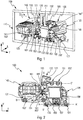
- la
figure 1 est une vue arrière de trois quart d'un dispositif lumineux selon l'invention ; - la
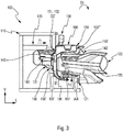
figure 2 est une vue arrière du dispositif lumineux représenté à lafigure 1 sans son support, afin de faciliter la compréhension de l'invention par le lecteur ; et - la
figure 3 est une coupe latérale d'un phare pour véhicule comprenant le dispositif lumineux représenté aux figures précédentes. - Dans la description qui va suivre, on se référera à une orientation en fonction des axes longitudinaux L, verticaux V et transversaux T, tels qu'ils sont définis arbitrairement par le trièdre L,V,T représenté sur les figures. L'axe longitudinal L correspond à la direction d'émission principale des rayons émis par le dispositif lumineux selon l'invention.
- Un dispositif lumineux 100 selon la présente invention comporte un support 110, représenté schématiquement sur les
figures 1 et3 , sur lequel sont fixés deux modules lumineux distincts, parmi lesquels on distingue un premier module 120 et un deuxième module 140 lumineux. Ces deux modules sont décalés l'un par rapport, aussi bien transversalement (tel que visible sur lafigure 1 ), c'est-à-dire que l'un des modules est disposé vers le centre du véhicule et l'autre vers l'extérieur du véhicule, que verticalement ou longitudinalement (tel que visible sur lafigure 3 notamment). - Sans sortir du contexte de l'invention, chaque module lumineux peut consister en un module émetteur d'un faisceau Code et/ou Route, que l'on souhaite pouvoir faire pivoter autour d'un axe transversal sensiblement horizontal, de manière à régler la hauteur des faisceaux projetés, par exemple en fonction de l'assiette du véhicule.
- Le premier module lumineux 120 est fixé au support 110 par l'intermédiaire d'éléments de pivotement, et plus particulièrement de deux premiers éléments de liaison rotule 121 et 122, configurés pour former une première liaison pivot configurée pour permettre le pivotement du module lumineux selon un premier axe de rotation (AA'). On peut noter que le premier axe de rotation (AA') est parallèle ou sensiblement parallèle au plan défini par la face avant 123 par laquelle la lumière est émise par le premier module 120 lumineux.
- Tel que cela est visible sur les figures, le premier axe de rotation (AA') est disposé en partie basse du premier module 120 lumineux. On définira par la suite la notion de partie basse en regard des autres axes de rotation du dispositif.
- Le deuxième module lumineux 140 est fixé au support 110 par l'intermédiaire d'une première platine 130, qui comporte d'une part un plateau 131, sur lequel est fixé le deuxième module 140 lumineux, et d'autre part un bras 132 s'étendant le long d'une face latérale 141 du deuxième module, selon une direction sensiblement perpendiculaire au plateau 131.
- La première platine 130 est fixée au support 110 par l'intermédiaire d'un point de fixation réglable 171 et de deux points de fixation fixes, parmi lesquels un élément de liaison pivot 133 et un élément de liaison sphérique 134, qui forment des éléments de pivotement définissant un deuxième axe de rotation (BB') de la première platine sur le support et donc une deuxième liaison pivot.
- Par point de fixation fixe, on entend que le centre de la liaison reste immobile par rapport à une position d'origine, et au cours du déplacement relatif de la première platine par rapport au support, tandis que par point de fixation réglable, on entend que le centre de la liaison peut être déplacé par rapport à une position d'origine.
- Les points fixes sont agencés de manière à former cette deuxième liaison pivot et permettre, notamment sous l'effet d'un effort exercé au niveau du point de fixation réglable, le pivotement de la première platine 130 autour d'un deuxième axe (BB') de rotation qui est parallèle au premier axe (AA') décrit précédemment. Le deuxième module 140 est fixé sur le plateau 131 de sorte qu'il suit le pivotement de la première platine 130 et de sorte que sa face avant 142, par laquelle est émise la lumière, soit parallèle au deuxième axe de rotation (BB').
- Tel que cela est visible sur les figures, le deuxième axe de rotation (BB') est disposé en partie basse du deuxième module 140 lumineux. On définira par la suite la notion de partie basse en regard des autres axes de rotation du dispositif.
- Selon l'invention, le dispositif lumineux comporte un dispositif d'actionnement 170 et des éléments d'entraînement reliant les deux modules entre eux.
- Dans l'exemple illustré, le dispositif d'actionnement 170 est agencé au voisinage du point de fixation réglable 171. Il peut notamment comporter une tige de sortie d'un vérin, représentée schématiquement sur les
figures 1 et3 , et pilotée en translation par des instructions de commande en provenance d'un module de commande approprié. Le déplacement en translation de la tige du dispositif d'actionnement 170 exerce sur le point de fixation réglable 171, et la première platine 130 qui porte celui-ci, une première force F1, orientée selon une première direction perpendiculaire au deuxième axe de rotation (BB') de la deuxième liaison pivot et sensiblement longitudinale. - Les éléments d'entraînement selon l'invention comportent le cas échéant la première platine 130, ainsi qu'au moins une deuxième platine 150, d'une part reliée à la première platine et d'autre part fixée au support 110 par l'intermédiaire d'éléments de pivotement et plus particulièrement de deux deuxièmes éléments de liaison rotule 151 et 152. Les deux deuxièmes éléments de liaison rotule 151, 152 associés à la deuxième platine 150 forment une troisième liaison pivot, configurée pour permettre le pivotement de la deuxième platine selon un troisième axe (CC') de rotation, notamment parallèle aux axes précédemment décrits (AA'), (BB').
- Tel que cela est visible sur les figures, le troisième axe de rotation (CC') est disposé en partie haute de la deuxième platine 150. On définira par la suite la notion de partie haute en regard des autres axes de rotation du dispositif.
- La deuxième platine 150 est agencée dans le dispositif lumineux 100 de manière à être positionnée à l'arrière du premier module 120, c'est-à-dire positionnée à l'opposé de la face avant 123 du module par rapport à la direction longitudinale définie ici par le trièdre L,V,T. La deuxième platine 150 comprend au moins un bras de connexion 153 s'étendant en direction de la face latérale 141 du deuxième module 140 qui est en vis-à-vis du premier module 120. Plus exactement, le bras de connexion s'étend de manière à présenter une portion de recouvrement 153' d'une partie du bras 132 de la première platine 130.
- La deuxième platine 150 est jointe à la première platine 130 au niveau de cette portion de recouvrement 153', par l'intermédiaire d'une liaison glissière 160, formée par la coopération d'un ergot 161, solidaire du bras 132, et d'une fente 154 ménagée à cet effet dans le bras de connexion 153 et dans laquelle est retenue en coulissement une tête 163 formée à l'extrémité libre de l'ergot. Dans l'exemple illustré, la fente 154 débouche sur un bord du bras de connexion 153 et la tête 163 de l'ergot 161 est insérée par l'extrémité débouchante de la fente. On comprend que sans sortir du contexte de l'invention, on pourrait prévoir une lumière ménagée dans le bras de connexion et une tête 163 de l'ergot montée par encliquetage élastique dans cette lumière, dès lors que la tête peut coulisser à l'intérieur de la lumière.
- La fente 154 est configurée pour permettre le déplacement de la tête 163 de l'ergot le long du bras de connexion 153. Plus précisément, la fente définit un chemin de guidage qui s'étend selon un quatrième axe (DD') perpendiculaire au deuxième axe de rotation (BB') et au troisième axe de rotation (CC'). Par ailleurs, la portion de recouvrement 153' du bras de guidage 153, et à tout le moins la fente 154, est positionnée verticalement entre le deuxième axe de rotation (BB') et le troisième axe de rotation (CC'). Tel que cela sera notamment explicité plus en détails ci-après dans la description du fonctionnement du dispositif, la position de cette portion de recouvrement permet la formation d'un bras de levier qui facilite la transformation des mouvements d'un module à l'autre.
- La deuxième platine 150 présente sensiblement une forme en U, avec une base 150' qui s'étend en regard d'une face arrière, opposée à la face avant 123, du premier module 120, et qui est prolongée à chacune de ses extrémités verticales par une ailette. Dans l'exemple illustré, la base 150' et le bras de connexion s'étendent dans le prolongement l'un de l'autre, dans un même plan.
- Une ailette supérieure de cette deuxième platine prolonge sensiblement perpendiculairement la base 150', en formant un plateau 156 qui s'étend au-dessus du premier module 120 et qui est configuré pour servir de support à un ventilateur 180 formant organe de refroidissement d'au moins le premier module. Le plateau 156 est défini par une paroi de fond 156' et par des parois de butée 156", dont au moins une paroi de butée arrière qui s'étend dans le prolongement du plan défini par la base 150' et qui porte les deux deuxièmes éléments de liaison rotule 151 et 152, formant la troisième liaison pivot d'axe (CC').
- Une ailette inférieure de cette deuxième platine prolonge la base 150' à l'opposé du plateau 156, en formant un appendice 155 recourbé à l'extrémité libre de laquelle est disposé un organe de liaison sphérique 157 avec le premier module 120 lumineux.
- Tel que cela a été précisé précédemment, le dispositif d'actionnement 170 s'étend entre le support 110 et le deuxième module lumineux 140, par l'intermédiaire de la première platine 130. Plus précisément, le dispositif d'actionnement 170 est agencé pour pousser sur la première platine 130 au niveau du point de fixation réglable 171, de manière à faire pivoter de façon réversible la première platine autour du deuxième axe (BB'). Par pivotement réversible, on comprend que lorsque le dispositif d'actionnement 170 applique une première force sur la première platine selon un premier sens, dans la première direction, la première platine pivote autour du premier axe de rotation selon un premier sens de rotation, et que lorsque ce dispositif d'actionnement 170 applique une première force sur la première platine selon un sens inverse au premier sens, toujours dans la première direction, la première platine pivote autour du premier axe de rotation selon un sens de rotation inverse au premier sens de rotation. On peut ainsi faire pivoter le deuxième module lumineux et par extension le premier module, en fonction des instructions de commande reçues par le dispositif d'actionnement, dans un sens ou dans l'autre, de manière à faire pointer le faisceau émis par chacun de ces modules plus ou moins loin sur la scène de route.
- Il peut être noté, notamment sur la
figure 3 , que le dispositif est configuré pour que le point de fixation réglable 171 soit centré sur le quatrième axe (DD'). Le point de fixation réglable 171 est positionné sur cet axe de sorte que l'ergot 160 soit situé entre ce point de fixation réglable et l'élément de liaison sphérique 134. De préférence, le point de fixation réglable 171 est positionné à la hauteur du troisième axe (CC'). - Par ailleurs, il peut être noté, notamment sur la
figure 2 , que les première et deuxième liaison pivot, d'axe respectif le premier axe (AA') et le deuxième axe (BB'), sont disposées en partie basse du dispositif tandis que la troisième liaison pivot de troisième axe (CC') est disposée en partie haute du dispositif, les parties basse et haute du dispositif pouvant être distinguées comme s'étendant de part et d'autre d'un plan horizontal passant sensiblement par la liaison glissière 160 et notamment la tête 163 de l'ergot 160. - On va maintenant décrire le fonctionnement du basculement des modules lumineux dans le dispositif selon l'invention, dans un contexte arbitraire dans lequel on souhaite abaisser le faisceau d'éclairage émis par les modules.
- Une première force F1 est appliquée sur le bras 132 par l'intermédiaire du dispositif d'actionnement 170, au niveau du point de fixation réglable 171. La force est, dans le contexte arbitraire défini précédemment, telle que la tige du dispositif d'actionnement pousse sur la première platine 130. Celle-ci pivote alors autour de son axe (BB') de rotation dans un premier sens S1, sens horaire si l'on se réfère à l'orientation du dispositif visible sur les
figures 1 et3 . Le pivotement du plateau 131, solidaire en rotation de la première platine, dans ce même premier sens, ici horaire, génère le pivotement du deuxième module 140 fixé sur le plateau 131 et l'inclinaison du faisceau lumineux émis par ce deuxième module. - Simultanément, les éléments d'entraînement, et notamment la première platine et la deuxième platine, agissent pour permettre le basculement du deuxième module lumineux dans le même premier sens S1 et dans les mêmes proportions que ceux du basculement du premier module lumineux.
- Le pivotement du bras 132 autour du deuxième axe (BB') entraîne en déplacement l'ergot 161 et la tête 163 retenue par ailleurs dans la fente 154 ménagée dans le bras de connexion 153 solidaire de la deuxième platine 150. Localement, au niveau de l'ergot et de la fente, la deuxième platine 150 est entraînée de façon similaire à la première platine 130. La deuxième platine 150 est articulée sur le support 110 de manière à pouvoir pivoter autour du troisième axe (CC') de rotation, de sorte que le déplacement local du bras de connexion 153 génère un pivotement de la deuxième platine 150 autour de ce troisième axe. On constate que la position de la portion de recouvrement 153', c'est-à-dire la zone de liaison entre la première platine et la deuxième platine, est prévue entre le deuxième axe (BB') et le troisième axe (CC'), de sorte que le pivotement dans un sens, horaire ou antihoraire, de la première platine autour du deuxième axe (BB') se transforme en un pivotement dans un sens inverse, antihoraire ou horaire, de la deuxième platine autour du troisième axe (CC').
- Dans le contexte arbitraire choisi précédemment, la deuxième platine 150 pivote dans le sens antihoraire, inverse au premier sens S1, autour du troisième axe (CC') défini par la liaison pivot formée par les deux deuxièmes éléments de rotules 151,152.
- De ce fait, l'appendice 155 de la deuxième platine est déplacé et l'organe de liaison sphérique 157 avec le premier module 120 lumineux qui est porté à l'extrémité libre de l'appendice se déplace également, en exerçant une deuxième force F2 sur le premier module 120 selon une deuxième direction, qui est perpendiculaire, ou sensiblement perpendiculaire à la première direction selon laquelle est exercée la première force F1 sur le deuxième module. Dans le contexte arbitraire choisi précédemment, la deuxième force F2 est exercée de manière à pousser sous le premier module lumineux, en visant à l'éloigner de l'appendice.
- La deuxième force F2 s'exerce selon une telle deuxième direction du fait de l'agencement de l'appendice recourbée, et de la position sous le premier module 120 de l'organe de liaison sphérique 157, longitudinalement en avant par rapport au troisième axe (CC'). Par longitudinalement en avant, on comprend que l'organe de liaison sphérique 157 est situé plus près de la face avant 123 du premier module 120 que les deux deuxièmes éléments de rotule 151,152.
- On peut noter la position de l'organe de liaison sphérique 157 par rapport aux deux premiers éléments de rotule 121,122 définissant le premier axe de rotation (AA'), à savoir une position longitudinale de l'organe de liaison sphérique en retrait par rapport au premier axe de rotation (AA'). L'organe de liaison sphérique 157, porté en extrémité de l'appendice 155, se situe entre la première liaison pivot, formée par les deux premiers éléments de rotule 121, 122, et la troisième liaison pivot formée par les deux deuxièmes éléments de rotule 151, 152.
- Du fait de cette position, le mouvement de basculement de la deuxième platine implique une poussée exercée vers le haut sous le premier module lumineux 120, c'est-à-dire dans le sens de la flèche F2 illustrée sur la
figure 3 , et cette poussée entraîne un pivotement du premier module lumineux 120 autour du premier axe de rotation (AA'), dans le même premier sens S1 que le sens de pivotement du deuxième module 130. - L'invention permet ainsi de transmettre au deux modules lumineux 120 et 140 un mouvement de pivotement synchronisé et identique, permettant de régler en même temps l'inclinaison des faisceaux lumineux que les modules projettent.
- Dans le fonctionnement qui vient d'être décrit, il convient de noter la deuxième platine sert d'élément intermédiaire entre l'ensemble formé par le deuxième module lumineux 140 et la première platine 130 d'une part et le premier module lumineux 120 d'autre part.
- Lorsque la deuxième platine 150 pivote par l'intermédiaire de la troisième liaison pivot, le plateau 156 suit le pivotement. Dans le sens de pivotement antihoraire précédemment décrit, le plateau 156, situé longitudinalement en avant de la troisième liaison pivot formée par les deux deuxièmes éléments de rotule 151, 152, se déplace en s'écartant de la position du premier module lumineux 120. On crée ainsi un dégagement permettant par la suite le pivotement, dans le sens de pivotement horaire, du premier module lumineux 120 sans que l'arrière de ce premier module lumineux n'entre en contact avec la paroi de fond 156' du plateau 156.
- Sur la
figure 3 , on a rendu particulièrement visible la caractéristique selon laquelle chacun des éléments formant les éléments d'entraînement, à savoir ici notamment la première platine 130 et la deuxième platine 150, sont agencés en retrait, dans la direction longitudinale, des faces avant 123, 143 respectives des modules lumineux par lesquelles sont susceptibles d'être émise la lumière. En d'autres termes, la partie la plus avancée de ces éléments d'entraînement, ici l'extrémité libre du plateau 156, est située en retrait de la face d'émission de rayons lumineux la plus reculée. De la sorte, aucun rayon émis par l'un des modules lumineux ne risque d'être dévié par des éléments formant les éléments d'entraînement, non configurés pour participer à la formation d'un faisceau lumineux règlementaire. - On pourra notamment dans ce cas prévoir de configurer la face avant de chacun des éléments formant les éléments d'entraînement pour générer une fonction esthétique. Ces faces, pouvant être visibles par un tiers depuis l'extérieur du véhicule, pourront par exemple être opaques, ou présenter un état de surface particulier.
- Tel que cela a pu être déjà précisé précédemment, le dispositif lumineux selon l'invention, notamment par l'agencement des éléments d'entraînement permettant la transformation de direction des forces exercées sur l'un et l'autre des modules lumineux, permet de déplacer simultanément les deux modules lumineux en pivotement, tout en escamotant les éléments composant ces éléments d'entraînement. Il convient de noter que la configuration décrite permet d'ajuster facilement les dimensions des platines et donc des éléments d'entraînement, ce qui permet de prévoir une plus grande liberté dans l'agencement des modules entre eux, et notamment dans des écartements plus ou moins grand, sans que la fragilité des éléments d'entraînement soient mise en cause.
Claims (15)
- Dispositif lumineux (100) de véhicule automobile comprenant un support (110) et deux modules lumineux distincts (120,140), chaque module lumineux étant monté sur le support (110) par l'intermédiaire d'éléments de pivotement (121, 122, 133, 134) définissant un axe de rotation (AA', BB') propre à chacun des modules, et dans lequel des éléments d'entraînement reliant les deux modules lumineux sont prévus pour entraîner en pivotement un premier module lumineux (120) en fonction du pivotement d'un deuxième module lumineux (140), caractérisé en ce qu'il comprend en outre un dispositif d'actionnement (170), configuré pour exercer une première force (F1), selon une première direction, sur le deuxième module lumineux (140), les éléments d'entraînement (130, 150) étant configurés pour transformer la première force (F1) en une deuxième force (F2) exercée, selon une deuxième direction distincte de la première direction de la première force, sur le premier module lumineux (120).
- Dispositif lumineux selon la revendication précédente, caractérisé en ce que la première direction selon laquelle est exercée la première force (F1) et la deuxième direction selon laquelle est exercée la deuxième force (F2) sont perpendiculaires.
- Dispositif lumineux selon l'une des revendications 1 ou 2, caractérisé en ce que le premier module lumineux (120) est monté pivotant sur le support (110) autour d'un premier axe de rotation (AA') et en ce que le deuxième module lumineux (140) est monté pivotant sur le support (110) autour d'un deuxième axe de rotation (BB'), le premier axe de rotation (AA') étant parallèle au deuxième axe de rotation (BB').
- Dispositif lumineux selon l'une des revendications précédentes, caractérisé en ce que les éléments d'entraînement comprennent au moins une première platine (130) sur laquelle est fixé le deuxième module lumineux (140), la première platine étant montée pivotante sur le support (110) autour du deuxième axe de rotation (BB').
- Dispositif selon la revendication précédente, caractérisé en ce que le dispositif d'actionnement (170) est configuré pour exercer la première force (F1), selon la première direction, sur le deuxième module lumineux (120) par l'intermédiaire de la première platine (130).
- Dispositif lumineux selon la revendication 4 ou 5, caractérisé en ce que les éléments d'entraînement comprennent une deuxième platine (150) reliée à la première platine (130) et configurée pour exercer la deuxième force (F2) selon la deuxième direction sur le premier module lumineux (120).
- Dispositif lumineux selon la revendication précédente, caractérisé en ce que la deuxième platine (150) est montée pivotante sur le support (110), autour d'un troisième axe de rotation (CC').
- Dispositif lumineux selon la revendication précédente, caractérisé en ce que le troisième axe de rotation (CC') est parallèle au deuxième de rotation (BB').
- Dispositif lumineux selon l'une des revendications 6 à 8, caractérisé en ce que la deuxième platine (150) est reliée à la première platine par l'intermédiaire d'une liaison glissière (160).
- Dispositif lumineux selon la revendication précédente, caractérisé en ce que l'axe de la liaison glissière (160) est sensiblement perpendiculaire à un axe de rotation (BB') défini par la deuxième liaison pivot (133, 134) et à la première direction selon laquelle est exercée la première force (F1).
- Dispositif lumineux selon l'une des revendications 9 ou 10, en combinaison avec les revendications 3 et 7, caractérisé en ce que la liaison glissière (160) est située entre le premier axe de rotation (AA') et le troisième axe de rotation (BB').
- Dispositif lumineux selon l'une des revendications 9 à 11, caractérisé en ce que le dispositif d'actionnement (170) exerce la première force (F1) sur la première platine (130) en un point réglable (171), la liaison glissière étant centrée sur un quatrième axe (DD') défini entre ce point réglable et un élément de pivotement (134) de la première liaison pivot.
- Dispositif lumineux selon l'une des revendications 8 à 10, caractérisé en ce que la deuxième platine (150) comprend un appendice (155) destiné à appliquer la deuxième force (F2) sur le deuxième module lumineux (120), via un organe de liaison (157), et en ce que l'appendice est configuré pour que l'organe de liaison (157) soit disposé entre le premier axe de rotation (AA') et le troisième axe de rotation (CC').
- Dispositif lumineux selon l'une des revendications 6 à 13, caractérisé en ce que la deuxième platine (150) comprend un plateau (156) servant de support pour un dispositif de ventilation (180) d'au moins le premier module lumineux (120).
- Dispositif lumineux selon l'une des revendications précédentes, caractérisé en ce que les éléments d'entraînement (130, 150, 160) sont en retrait des faces avant (123, 143) des modules lumineux (120, 140) émettant de la lumière.
Applications Claiming Priority (1)
| Application Number | Priority Date | Filing Date | Title |
|---|---|---|---|
| FR1658122A FR3055266B1 (fr) | 2016-09-01 | 2016-09-01 | Dispositif lumineux de vehicule automobile |
Publications (2)
| Publication Number | Publication Date |
|---|---|
| EP3290270A1 true EP3290270A1 (fr) | 2018-03-07 |
| EP3290270B1 EP3290270B1 (fr) | 2022-10-26 |
Family
ID=57906692
Family Applications (1)
| Application Number | Title | Priority Date | Filing Date |
|---|---|---|---|
| EP17184938.3A Active EP3290270B1 (fr) | 2016-09-01 | 2017-08-04 | Dispositif lumineux de véhicule automobile |
Country Status (3)
| Country | Link |
|---|---|
| EP (1) | EP3290270B1 (fr) |
| CN (1) | CN108302488B (fr) |
| FR (1) | FR3055266B1 (fr) |
Cited By (2)
| Publication number | Priority date | Publication date | Assignee | Title |
|---|---|---|---|---|
| FR3102959A1 (fr) * | 2019-11-13 | 2021-05-14 | Valeo Vision | Dispositif lumineux d’un véhicule automobile, en particulier un phare avant ou un projecteur de véhicule |
| EP4173892A1 (fr) * | 2021-10-29 | 2023-05-03 | Valeo Vision | Dispositif lumineux pour automobile |
Families Citing this family (2)
| Publication number | Priority date | Publication date | Assignee | Title |
|---|---|---|---|---|
| FR3098633B1 (fr) * | 2019-07-09 | 2021-07-02 | Aml Systems | Système d’entraînement pour entraîner en rotation un premier dispositif par rapport à un deuxième dispositif autour un axe de rotation. |
| FR3109621B1 (fr) * | 2020-04-27 | 2022-04-08 | Valeo Vision | Dispositif d’éclairage de véhicule automobile présentant un aspect sans glace |
Citations (3)
| Publication number | Priority date | Publication date | Assignee | Title |
|---|---|---|---|---|
| EP2394850A1 (fr) * | 2010-06-10 | 2011-12-14 | Valeo Vision | Système de correction manuel commun pour deux dispositifs d'éclairage dont un à correction automatique |
| EP2796320A1 (fr) * | 2013-04-22 | 2014-10-29 | Automotive Lighting Reutlingen GmbH | Phare de véhicule automobile |
| US20150117043A1 (en) * | 2013-10-29 | 2015-04-30 | Koito Manufacturing Co., Ltd. | Vehicular lamp unit |
Family Cites Families (4)
| Publication number | Priority date | Publication date | Assignee | Title |
|---|---|---|---|---|
| EP2754951B1 (fr) * | 2011-09-07 | 2017-01-11 | Koito Manufacturing Co., Ltd. | Actionneur et phare avant de véhicule |
| US9120422B2 (en) * | 2012-06-29 | 2015-09-01 | Valeo North America, Inc. | Multiple headlamp adjuster linkage |
| KR101398222B1 (ko) * | 2012-07-23 | 2014-05-22 | 현대모비스 주식회사 | 차량용 헤드 램프 및 이를 포함하는 차량 |
| CN104296093B (zh) * | 2014-09-05 | 2017-02-01 | 上海小糸车灯有限公司 | 一种用于车灯可调支架连接的双球头连杆连接装置 |
-
2016
- 2016-09-01 FR FR1658122A patent/FR3055266B1/fr not_active Expired - Fee Related
-
2017
- 2017-08-04 EP EP17184938.3A patent/EP3290270B1/fr active Active
- 2017-09-01 CN CN201710779467.4A patent/CN108302488B/zh active Active
Patent Citations (3)
| Publication number | Priority date | Publication date | Assignee | Title |
|---|---|---|---|---|
| EP2394850A1 (fr) * | 2010-06-10 | 2011-12-14 | Valeo Vision | Système de correction manuel commun pour deux dispositifs d'éclairage dont un à correction automatique |
| EP2796320A1 (fr) * | 2013-04-22 | 2014-10-29 | Automotive Lighting Reutlingen GmbH | Phare de véhicule automobile |
| US20150117043A1 (en) * | 2013-10-29 | 2015-04-30 | Koito Manufacturing Co., Ltd. | Vehicular lamp unit |
Cited By (4)
| Publication number | Priority date | Publication date | Assignee | Title |
|---|---|---|---|---|
| FR3102959A1 (fr) * | 2019-11-13 | 2021-05-14 | Valeo Vision | Dispositif lumineux d’un véhicule automobile, en particulier un phare avant ou un projecteur de véhicule |
| WO2021094494A1 (fr) * | 2019-11-13 | 2021-05-20 | Valeo Vision | Dispositif lumineux d'un véhicule automobile, en particulier un phare avant ou un projecteur de véhicule |
| US11846398B2 (en) | 2019-11-13 | 2023-12-19 | Valeo Vision | Lighting device for a motor vehicle having a plate that can be translated horizontally and vertically relative to a surface of the plate |
| EP4173892A1 (fr) * | 2021-10-29 | 2023-05-03 | Valeo Vision | Dispositif lumineux pour automobile |
Also Published As
| Publication number | Publication date |
|---|---|
| CN108302488A (zh) | 2018-07-20 |
| FR3055266B1 (fr) | 2019-04-05 |
| FR3055266A1 (fr) | 2018-03-02 |
| EP3290270B1 (fr) | 2022-10-26 |
| CN108302488B (zh) | 2022-03-18 |
Similar Documents
| Publication | Publication Date | Title |
|---|---|---|
| EP3290270B1 (fr) | Dispositif lumineux de véhicule automobile | |
| FR2636578A1 (fr) | Dispositif de reglage d'orientation pour projecteur de vehicule automobile | |
| EP3048359B1 (fr) | Module lumineux pour véhicule automobile | |
| EP1270322A1 (fr) | Dispositif d'éclairage à orientation variable | |
| EP2394850B1 (fr) | Système de correction manuel commun pour deux dispositifs d'éclairage dont un à correction automatique | |
| EP3127746B1 (fr) | Dispositif d'éclairage et/ou de signalisation d'un véhicule automobile comprenant au moins deux modules d'éclairage | |
| FR2804918A1 (fr) | Phare pour vehicule | |
| EP3238991A1 (fr) | Module lumineux rotatif | |
| EP0416998A1 (fr) | Projecteur de véhicule automobile à moyens de réglage en site perfectionnés | |
| EP2957821B1 (fr) | Module d'éclairage et /ou de signalisation rotatif | |
| CA1093428A (fr) | Dispositif de manoeuvre par levier pour les commandes de climatisation d'un vehicule | |
| EP3238992B1 (fr) | Module lumineux rotatif | |
| FR2800659A1 (fr) | Dispositif de deplacement d'un objet sensiblement parallelement a un plan | |
| FR2679183A1 (fr) | Installation d'essuie-glace. | |
| FR3069518B1 (fr) | Volet deployable a geometrie variable | |
| FR2900109A3 (fr) | Phare pour vehicules. | |
| WO2004044640A3 (fr) | Dispositif permettant de dévier un faisceau laser | |
| FR2601111A1 (fr) | Projecteur de vehicule automobile, a deux miroirs reglables mutuellement | |
| FR2764851A1 (fr) | Dispositif de reglage de l'orientation d'un faisceau lumineux emis par un projecteur de vehicule automobile | |
| EP0248716A1 (fr) | Commutateur pour vehicules automobiles | |
| EP4422922B1 (fr) | Dispositif d'éclairage pour un projecteur d'un véhicule | |
| EP2551153B1 (fr) | Ensemble d'un support de module optique et d'un dispositif de liaison apte à recevoir un moyen de réglage de la position de support | |
| FR2670461A1 (fr) | Plancher de vehicule, notamment du poste de pilotage d'un avion. | |
| FR2746730A1 (fr) | Dispositif de commande de l'orientation d'un faisceau emis p ar un projecteur de vehicule automobile et projecteur l'inco rporant | |
| WO2025202086A1 (fr) | Support d'une unite lumineuse mobile par rapport a une lentille de projection au sein d'un module lumineux pour vehicule automobile et procédé de fabrication |
Legal Events
| Date | Code | Title | Description |
|---|---|---|---|
| PUAI | Public reference made under article 153(3) epc to a published international application that has entered the european phase |
Free format text: ORIGINAL CODE: 0009012 |
|
| STAA | Information on the status of an ep patent application or granted ep patent |
Free format text: STATUS: THE APPLICATION HAS BEEN PUBLISHED |
|
| AK | Designated contracting states |
Kind code of ref document: A1 Designated state(s): AL AT BE BG CH CY CZ DE DK EE ES FI FR GB GR HR HU IE IS IT LI LT LU LV MC MK MT NL NO PL PT RO RS SE SI SK SM TR |
|
| AX | Request for extension of the european patent |
Extension state: BA ME |
|
| STAA | Information on the status of an ep patent application or granted ep patent |
Free format text: STATUS: REQUEST FOR EXAMINATION WAS MADE |
|
| 17P | Request for examination filed |
Effective date: 20180731 |
|
| RBV | Designated contracting states (corrected) |
Designated state(s): AL AT BE BG CH CY CZ DE DK EE ES FI FR GB GR HR HU IE IS IT LI LT LU LV MC MK MT NL NO PL PT RO RS SE SI SK SM TR |
|
| STAA | Information on the status of an ep patent application or granted ep patent |
Free format text: STATUS: EXAMINATION IS IN PROGRESS |
|
| 17Q | First examination report despatched |
Effective date: 20211028 |
|
| GRAP | Despatch of communication of intention to grant a patent |
Free format text: ORIGINAL CODE: EPIDOSNIGR1 |
|
| STAA | Information on the status of an ep patent application or granted ep patent |
Free format text: STATUS: GRANT OF PATENT IS INTENDED |
|
| INTG | Intention to grant announced |
Effective date: 20220525 |
|
| GRAS | Grant fee paid |
Free format text: ORIGINAL CODE: EPIDOSNIGR3 |
|
| GRAA | (expected) grant |
Free format text: ORIGINAL CODE: 0009210 |
|
| STAA | Information on the status of an ep patent application or granted ep patent |
Free format text: STATUS: THE PATENT HAS BEEN GRANTED |
|
| AK | Designated contracting states |
Kind code of ref document: B1 Designated state(s): AL AT BE BG CH CY CZ DE DK EE ES FI FR GB GR HR HU IE IS IT LI LT LU LV MC MK MT NL NO PL PT RO RS SE SI SK SM TR |
|
| REG | Reference to a national code |
Ref country code: GB Ref legal event code: FG4D Free format text: NOT ENGLISH |
|
| REG | Reference to a national code |
Ref country code: CH Ref legal event code: EP |
|
| REG | Reference to a national code |
Ref country code: DE Ref legal event code: R096 Ref document number: 602017062950 Country of ref document: DE |
|
| REG | Reference to a national code |
Ref country code: AT Ref legal event code: REF Ref document number: 1526822 Country of ref document: AT Kind code of ref document: T Effective date: 20221115 |
|
| REG | Reference to a national code |
Ref country code: IE Ref legal event code: FG4D Free format text: LANGUAGE OF EP DOCUMENT: FRENCH |
|
| REG | Reference to a national code |
Ref country code: LT Ref legal event code: MG9D |
|
| REG | Reference to a national code |
Ref country code: NL Ref legal event code: MP Effective date: 20221026 |
|
| REG | Reference to a national code |
Ref country code: AT Ref legal event code: MK05 Ref document number: 1526822 Country of ref document: AT Kind code of ref document: T Effective date: 20221026 |
|
| PG25 | Lapsed in a contracting state [announced via postgrant information from national office to epo] |
Ref country code: NL Free format text: LAPSE BECAUSE OF FAILURE TO SUBMIT A TRANSLATION OF THE DESCRIPTION OR TO PAY THE FEE WITHIN THE PRESCRIBED TIME-LIMIT Effective date: 20221026 |
|
| PG25 | Lapsed in a contracting state [announced via postgrant information from national office to epo] |
Ref country code: SE Free format text: LAPSE BECAUSE OF FAILURE TO SUBMIT A TRANSLATION OF THE DESCRIPTION OR TO PAY THE FEE WITHIN THE PRESCRIBED TIME-LIMIT Effective date: 20221026 Ref country code: PT Free format text: LAPSE BECAUSE OF FAILURE TO SUBMIT A TRANSLATION OF THE DESCRIPTION OR TO PAY THE FEE WITHIN THE PRESCRIBED TIME-LIMIT Effective date: 20230227 Ref country code: NO Free format text: LAPSE BECAUSE OF FAILURE TO SUBMIT A TRANSLATION OF THE DESCRIPTION OR TO PAY THE FEE WITHIN THE PRESCRIBED TIME-LIMIT Effective date: 20230126 Ref country code: LT Free format text: LAPSE BECAUSE OF FAILURE TO SUBMIT A TRANSLATION OF THE DESCRIPTION OR TO PAY THE FEE WITHIN THE PRESCRIBED TIME-LIMIT Effective date: 20221026 Ref country code: FI Free format text: LAPSE BECAUSE OF FAILURE TO SUBMIT A TRANSLATION OF THE DESCRIPTION OR TO PAY THE FEE WITHIN THE PRESCRIBED TIME-LIMIT Effective date: 20221026 Ref country code: ES Free format text: LAPSE BECAUSE OF FAILURE TO SUBMIT A TRANSLATION OF THE DESCRIPTION OR TO PAY THE FEE WITHIN THE PRESCRIBED TIME-LIMIT Effective date: 20221026 Ref country code: AT Free format text: LAPSE BECAUSE OF FAILURE TO SUBMIT A TRANSLATION OF THE DESCRIPTION OR TO PAY THE FEE WITHIN THE PRESCRIBED TIME-LIMIT Effective date: 20221026 |
|
| PG25 | Lapsed in a contracting state [announced via postgrant information from national office to epo] |
Ref country code: RS Free format text: LAPSE BECAUSE OF FAILURE TO SUBMIT A TRANSLATION OF THE DESCRIPTION OR TO PAY THE FEE WITHIN THE PRESCRIBED TIME-LIMIT Effective date: 20221026 Ref country code: PL Free format text: LAPSE BECAUSE OF FAILURE TO SUBMIT A TRANSLATION OF THE DESCRIPTION OR TO PAY THE FEE WITHIN THE PRESCRIBED TIME-LIMIT Effective date: 20221026 Ref country code: LV Free format text: LAPSE BECAUSE OF FAILURE TO SUBMIT A TRANSLATION OF THE DESCRIPTION OR TO PAY THE FEE WITHIN THE PRESCRIBED TIME-LIMIT Effective date: 20221026 Ref country code: IS Free format text: LAPSE BECAUSE OF FAILURE TO SUBMIT A TRANSLATION OF THE DESCRIPTION OR TO PAY THE FEE WITHIN THE PRESCRIBED TIME-LIMIT Effective date: 20230226 Ref country code: HR Free format text: LAPSE BECAUSE OF FAILURE TO SUBMIT A TRANSLATION OF THE DESCRIPTION OR TO PAY THE FEE WITHIN THE PRESCRIBED TIME-LIMIT Effective date: 20221026 Ref country code: GR Free format text: LAPSE BECAUSE OF FAILURE TO SUBMIT A TRANSLATION OF THE DESCRIPTION OR TO PAY THE FEE WITHIN THE PRESCRIBED TIME-LIMIT Effective date: 20230127 |
|
| P01 | Opt-out of the competence of the unified patent court (upc) registered |
Effective date: 20230528 |
|
| REG | Reference to a national code |
Ref country code: DE Ref legal event code: R097 Ref document number: 602017062950 Country of ref document: DE |
|
| PG25 | Lapsed in a contracting state [announced via postgrant information from national office to epo] |
Ref country code: SM Free format text: LAPSE BECAUSE OF FAILURE TO SUBMIT A TRANSLATION OF THE DESCRIPTION OR TO PAY THE FEE WITHIN THE PRESCRIBED TIME-LIMIT Effective date: 20221026 Ref country code: RO Free format text: LAPSE BECAUSE OF FAILURE TO SUBMIT A TRANSLATION OF THE DESCRIPTION OR TO PAY THE FEE WITHIN THE PRESCRIBED TIME-LIMIT Effective date: 20221026 Ref country code: EE Free format text: LAPSE BECAUSE OF FAILURE TO SUBMIT A TRANSLATION OF THE DESCRIPTION OR TO PAY THE FEE WITHIN THE PRESCRIBED TIME-LIMIT Effective date: 20221026 Ref country code: DK Free format text: LAPSE BECAUSE OF FAILURE TO SUBMIT A TRANSLATION OF THE DESCRIPTION OR TO PAY THE FEE WITHIN THE PRESCRIBED TIME-LIMIT Effective date: 20221026 Ref country code: CZ Free format text: LAPSE BECAUSE OF FAILURE TO SUBMIT A TRANSLATION OF THE DESCRIPTION OR TO PAY THE FEE WITHIN THE PRESCRIBED TIME-LIMIT Effective date: 20221026 |
|
| PG25 | Lapsed in a contracting state [announced via postgrant information from national office to epo] |
Ref country code: SK Free format text: LAPSE BECAUSE OF FAILURE TO SUBMIT A TRANSLATION OF THE DESCRIPTION OR TO PAY THE FEE WITHIN THE PRESCRIBED TIME-LIMIT Effective date: 20221026 Ref country code: AL Free format text: LAPSE BECAUSE OF FAILURE TO SUBMIT A TRANSLATION OF THE DESCRIPTION OR TO PAY THE FEE WITHIN THE PRESCRIBED TIME-LIMIT Effective date: 20221026 |
|
| PLBE | No opposition filed within time limit |
Free format text: ORIGINAL CODE: 0009261 |
|
| STAA | Information on the status of an ep patent application or granted ep patent |
Free format text: STATUS: NO OPPOSITION FILED WITHIN TIME LIMIT |
|
| 26N | No opposition filed |
Effective date: 20230727 |
|
| PG25 | Lapsed in a contracting state [announced via postgrant information from national office to epo] |
Ref country code: SI Free format text: LAPSE BECAUSE OF FAILURE TO SUBMIT A TRANSLATION OF THE DESCRIPTION OR TO PAY THE FEE WITHIN THE PRESCRIBED TIME-LIMIT Effective date: 20221026 |
|
| PG25 | Lapsed in a contracting state [announced via postgrant information from national office to epo] |
Ref country code: MC Free format text: LAPSE BECAUSE OF FAILURE TO SUBMIT A TRANSLATION OF THE DESCRIPTION OR TO PAY THE FEE WITHIN THE PRESCRIBED TIME-LIMIT Effective date: 20221026 |
|
| REG | Reference to a national code |
Ref country code: CH Ref legal event code: PL |
|
| PG25 | Lapsed in a contracting state [announced via postgrant information from national office to epo] |
Ref country code: MC Free format text: LAPSE BECAUSE OF FAILURE TO SUBMIT A TRANSLATION OF THE DESCRIPTION OR TO PAY THE FEE WITHIN THE PRESCRIBED TIME-LIMIT Effective date: 20221026 |
|
| PG25 | Lapsed in a contracting state [announced via postgrant information from national office to epo] |
Ref country code: LU Free format text: LAPSE BECAUSE OF NON-PAYMENT OF DUE FEES Effective date: 20230804 |
|
| GBPC | Gb: european patent ceased through non-payment of renewal fee |
Effective date: 20230804 |
|
| PG25 | Lapsed in a contracting state [announced via postgrant information from national office to epo] |
Ref country code: LU Free format text: LAPSE BECAUSE OF NON-PAYMENT OF DUE FEES Effective date: 20230804 Ref country code: CH Free format text: LAPSE BECAUSE OF NON-PAYMENT OF DUE FEES Effective date: 20230831 |
|
| REG | Reference to a national code |
Ref country code: BE Ref legal event code: MM Effective date: 20230831 |
|
| REG | Reference to a national code |
Ref country code: IE Ref legal event code: MM4A |
|
| PG25 | Lapsed in a contracting state [announced via postgrant information from national office to epo] |
Ref country code: IT Free format text: LAPSE BECAUSE OF FAILURE TO SUBMIT A TRANSLATION OF THE DESCRIPTION OR TO PAY THE FEE WITHIN THE PRESCRIBED TIME-LIMIT Effective date: 20221026 |
|
| PG25 | Lapsed in a contracting state [announced via postgrant information from national office to epo] |
Ref country code: IE Free format text: LAPSE BECAUSE OF NON-PAYMENT OF DUE FEES Effective date: 20230804 |
|
| PG25 | Lapsed in a contracting state [announced via postgrant information from national office to epo] |
Ref country code: GB Free format text: LAPSE BECAUSE OF NON-PAYMENT OF DUE FEES Effective date: 20230804 |
|
| PG25 | Lapsed in a contracting state [announced via postgrant information from national office to epo] |
Ref country code: IE Free format text: LAPSE BECAUSE OF NON-PAYMENT OF DUE FEES Effective date: 20230804 Ref country code: GB Free format text: LAPSE BECAUSE OF NON-PAYMENT OF DUE FEES Effective date: 20230804 |
|
| PG25 | Lapsed in a contracting state [announced via postgrant information from national office to epo] |
Ref country code: BE Free format text: LAPSE BECAUSE OF NON-PAYMENT OF DUE FEES Effective date: 20230831 |
|
| PG25 | Lapsed in a contracting state [announced via postgrant information from national office to epo] |
Ref country code: BG Free format text: LAPSE BECAUSE OF FAILURE TO SUBMIT A TRANSLATION OF THE DESCRIPTION OR TO PAY THE FEE WITHIN THE PRESCRIBED TIME-LIMIT Effective date: 20221026 |
|
| PG25 | Lapsed in a contracting state [announced via postgrant information from national office to epo] |
Ref country code: BG Free format text: LAPSE BECAUSE OF FAILURE TO SUBMIT A TRANSLATION OF THE DESCRIPTION OR TO PAY THE FEE WITHIN THE PRESCRIBED TIME-LIMIT Effective date: 20221026 |
|
| PG25 | Lapsed in a contracting state [announced via postgrant information from national office to epo] |
Ref country code: CY Free format text: LAPSE BECAUSE OF FAILURE TO SUBMIT A TRANSLATION OF THE DESCRIPTION OR TO PAY THE FEE WITHIN THE PRESCRIBED TIME-LIMIT; INVALID AB INITIO Effective date: 20170804 |
|
| PG25 | Lapsed in a contracting state [announced via postgrant information from national office to epo] |
Ref country code: HU Free format text: LAPSE BECAUSE OF FAILURE TO SUBMIT A TRANSLATION OF THE DESCRIPTION OR TO PAY THE FEE WITHIN THE PRESCRIBED TIME-LIMIT; INVALID AB INITIO Effective date: 20170804 |
|
| PGFP | Annual fee paid to national office [announced via postgrant information from national office to epo] |
Ref country code: DE Payment date: 20250812 Year of fee payment: 9 |
|
| PGFP | Annual fee paid to national office [announced via postgrant information from national office to epo] |
Ref country code: FR Payment date: 20250828 Year of fee payment: 9 |
|
| PG25 | Lapsed in a contracting state [announced via postgrant information from national office to epo] |
Ref country code: TR Free format text: LAPSE BECAUSE OF FAILURE TO SUBMIT A TRANSLATION OF THE DESCRIPTION OR TO PAY THE FEE WITHIN THE PRESCRIBED TIME-LIMIT Effective date: 20221026 |