EP3289334B1 - Vorrichtung und verfahren zum automatischen in-vitro-nachweis von analyten anhand einer spektralen zerlegung einer optischen antwort - Google Patents
Vorrichtung und verfahren zum automatischen in-vitro-nachweis von analyten anhand einer spektralen zerlegung einer optischen antwort Download PDFInfo
- Publication number
- EP3289334B1 EP3289334B1 EP16724687.5A EP16724687A EP3289334B1 EP 3289334 B1 EP3289334 B1 EP 3289334B1 EP 16724687 A EP16724687 A EP 16724687A EP 3289334 B1 EP3289334 B1 EP 3289334B1
- Authority
- EP
- European Patent Office
- Prior art keywords
- optical
- radiation
- reaction solution
- spectrometer
- spectral decomposition
- Prior art date
- Legal status (The legal status is an assumption and is not a legal conclusion. Google has not performed a legal analysis and makes no representation as to the accuracy of the status listed.)
- Active
Links
Images



Classifications
-
- G—PHYSICS
- G01—MEASURING; TESTING
- G01N—INVESTIGATING OR ANALYSING MATERIALS BY DETERMINING THEIR CHEMICAL OR PHYSICAL PROPERTIES
- G01N33/00—Investigating or analysing materials by specific methods not covered by groups G01N1/00 - G01N31/00
- G01N33/48—Biological material, e.g. blood, urine; Haemocytometers
- G01N33/50—Chemical analysis of biological material, e.g. blood, urine; Testing involving biospecific ligand binding methods; Immunological testing
- G01N33/52—Use of compounds or compositions for colorimetric, spectrophotometric or fluorometric investigation, e.g. use of reagent paper and including single- and multilayer analytical elements
-
- A—HUMAN NECESSITIES
- A61—MEDICAL OR VETERINARY SCIENCE; HYGIENE
- A61B—DIAGNOSIS; SURGERY; IDENTIFICATION
- A61B5/00—Measuring for diagnostic purposes; Identification of persons
- A61B5/0059—Measuring for diagnostic purposes; Identification of persons using light, e.g. diagnosis by transillumination, diascopy, fluorescence
- A61B5/0071—Measuring for diagnostic purposes; Identification of persons using light, e.g. diagnosis by transillumination, diascopy, fluorescence by measuring fluorescence emission
-
- G—PHYSICS
- G01—MEASURING; TESTING
- G01N—INVESTIGATING OR ANALYSING MATERIALS BY DETERMINING THEIR CHEMICAL OR PHYSICAL PROPERTIES
- G01N21/00—Investigating or analysing materials by the use of optical means, i.e. using sub-millimetre waves, infrared, visible or ultraviolet light
- G01N21/17—Systems in which incident light is modified in accordance with the properties of the material investigated
- G01N21/25—Colour; Spectral properties, i.e. comparison of effect of material on the light at two or more different wavelengths or wavelength bands
- G01N21/251—Colorimeters; Construction thereof
- G01N21/253—Colorimeters; Construction thereof for batch operation, i.e. multisample apparatus
-
- G—PHYSICS
- G01—MEASURING; TESTING
- G01N—INVESTIGATING OR ANALYSING MATERIALS BY DETERMINING THEIR CHEMICAL OR PHYSICAL PROPERTIES
- G01N21/00—Investigating or analysing materials by the use of optical means, i.e. using sub-millimetre waves, infrared, visible or ultraviolet light
- G01N21/17—Systems in which incident light is modified in accordance with the properties of the material investigated
- G01N21/25—Colour; Spectral properties, i.e. comparison of effect of material on the light at two or more different wavelengths or wavelength bands
- G01N21/27—Colour; Spectral properties, i.e. comparison of effect of material on the light at two or more different wavelengths or wavelength bands using photo-electric detection ; circuits for computing concentration
-
- G—PHYSICS
- G01—MEASURING; TESTING
- G01N—INVESTIGATING OR ANALYSING MATERIALS BY DETERMINING THEIR CHEMICAL OR PHYSICAL PROPERTIES
- G01N21/00—Investigating or analysing materials by the use of optical means, i.e. using sub-millimetre waves, infrared, visible or ultraviolet light
- G01N21/17—Systems in which incident light is modified in accordance with the properties of the material investigated
- G01N21/25—Colour; Spectral properties, i.e. comparison of effect of material on the light at two or more different wavelengths or wavelength bands
- G01N21/27—Colour; Spectral properties, i.e. comparison of effect of material on the light at two or more different wavelengths or wavelength bands using photo-electric detection ; circuits for computing concentration
- G01N21/274—Calibration, base line adjustment, drift correction
-
- G—PHYSICS
- G01—MEASURING; TESTING
- G01N—INVESTIGATING OR ANALYSING MATERIALS BY DETERMINING THEIR CHEMICAL OR PHYSICAL PROPERTIES
- G01N21/00—Investigating or analysing materials by the use of optical means, i.e. using sub-millimetre waves, infrared, visible or ultraviolet light
- G01N21/17—Systems in which incident light is modified in accordance with the properties of the material investigated
- G01N21/25—Colour; Spectral properties, i.e. comparison of effect of material on the light at two or more different wavelengths or wavelength bands
- G01N21/31—Investigating relative effect of material at wavelengths characteristic of specific elements or molecules, e.g. atomic absorption spectrometry
- G01N21/314—Investigating relative effect of material at wavelengths characteristic of specific elements or molecules, e.g. atomic absorption spectrometry with comparison of measurements at specific and non-specific wavelengths
-
- G—PHYSICS
- G01—MEASURING; TESTING
- G01N—INVESTIGATING OR ANALYSING MATERIALS BY DETERMINING THEIR CHEMICAL OR PHYSICAL PROPERTIES
- G01N21/00—Investigating or analysing materials by the use of optical means, i.e. using sub-millimetre waves, infrared, visible or ultraviolet light
- G01N21/62—Systems in which the material investigated is excited whereby it emits light or causes a change in wavelength of the incident light
- G01N21/63—Systems in which the material investigated is excited whereby it emits light or causes a change in wavelength of the incident light optically excited
- G01N21/64—Fluorescence; Phosphorescence
- G01N21/6428—Measuring fluorescence of fluorescent products of reactions or of fluorochrome labelled reactive substances, e.g. measuring quenching effects, using measuring "optrodes"
-
- G—PHYSICS
- G01—MEASURING; TESTING
- G01N—INVESTIGATING OR ANALYSING MATERIALS BY DETERMINING THEIR CHEMICAL OR PHYSICAL PROPERTIES
- G01N21/00—Investigating or analysing materials by the use of optical means, i.e. using sub-millimetre waves, infrared, visible or ultraviolet light
- G01N21/62—Systems in which the material investigated is excited whereby it emits light or causes a change in wavelength of the incident light
- G01N21/63—Systems in which the material investigated is excited whereby it emits light or causes a change in wavelength of the incident light optically excited
- G01N21/64—Fluorescence; Phosphorescence
- G01N21/645—Specially adapted constructive features of fluorimeters
-
- G—PHYSICS
- G01—MEASURING; TESTING
- G01N—INVESTIGATING OR ANALYSING MATERIALS BY DETERMINING THEIR CHEMICAL OR PHYSICAL PROPERTIES
- G01N21/00—Investigating or analysing materials by the use of optical means, i.e. using sub-millimetre waves, infrared, visible or ultraviolet light
- G01N21/75—Systems in which material is subjected to a chemical reaction, the progress or the result of the reaction being investigated
- G01N21/77—Systems in which material is subjected to a chemical reaction, the progress or the result of the reaction being investigated by observing the effect on a chemical indicator
-
- G—PHYSICS
- G01—MEASURING; TESTING
- G01N—INVESTIGATING OR ANALYSING MATERIALS BY DETERMINING THEIR CHEMICAL OR PHYSICAL PROPERTIES
- G01N35/00—Automatic analysis not limited to methods or materials provided for in any single one of groups G01N1/00 - G01N33/00; Handling materials therefor
- G01N35/00584—Control arrangements for automatic analysers
-
- G—PHYSICS
- G01—MEASURING; TESTING
- G01N—INVESTIGATING OR ANALYSING MATERIALS BY DETERMINING THEIR CHEMICAL OR PHYSICAL PROPERTIES
- G01N35/00—Automatic analysis not limited to methods or materials provided for in any single one of groups G01N1/00 - G01N33/00; Handling materials therefor
- G01N35/02—Automatic analysis not limited to methods or materials provided for in any single one of groups G01N1/00 - G01N33/00; Handling materials therefor using a plurality of sample containers moved by a conveyor system past one or more treatment or analysis stations
-
- G—PHYSICS
- G01—MEASURING; TESTING
- G01N—INVESTIGATING OR ANALYSING MATERIALS BY DETERMINING THEIR CHEMICAL OR PHYSICAL PROPERTIES
- G01N21/00—Investigating or analysing materials by the use of optical means, i.e. using sub-millimetre waves, infrared, visible or ultraviolet light
- G01N21/62—Systems in which the material investigated is excited whereby it emits light or causes a change in wavelength of the incident light
- G01N21/63—Systems in which the material investigated is excited whereby it emits light or causes a change in wavelength of the incident light optically excited
- G01N21/64—Fluorescence; Phosphorescence
- G01N2021/6417—Spectrofluorimetric devices
-
- G—PHYSICS
- G01—MEASURING; TESTING
- G01N—INVESTIGATING OR ANALYSING MATERIALS BY DETERMINING THEIR CHEMICAL OR PHYSICAL PROPERTIES
- G01N21/00—Investigating or analysing materials by the use of optical means, i.e. using sub-millimetre waves, infrared, visible or ultraviolet light
- G01N21/62—Systems in which the material investigated is excited whereby it emits light or causes a change in wavelength of the incident light
- G01N21/63—Systems in which the material investigated is excited whereby it emits light or causes a change in wavelength of the incident light optically excited
- G01N21/64—Fluorescence; Phosphorescence
- G01N2021/6417—Spectrofluorimetric devices
- G01N2021/6419—Excitation at two or more wavelengths
-
- G—PHYSICS
- G01—MEASURING; TESTING
- G01N—INVESTIGATING OR ANALYSING MATERIALS BY DETERMINING THEIR CHEMICAL OR PHYSICAL PROPERTIES
- G01N21/00—Investigating or analysing materials by the use of optical means, i.e. using sub-millimetre waves, infrared, visible or ultraviolet light
- G01N21/62—Systems in which the material investigated is excited whereby it emits light or causes a change in wavelength of the incident light
- G01N21/63—Systems in which the material investigated is excited whereby it emits light or causes a change in wavelength of the incident light optically excited
- G01N21/64—Fluorescence; Phosphorescence
- G01N2021/6417—Spectrofluorimetric devices
- G01N2021/6421—Measuring at two or more wavelengths
-
- G—PHYSICS
- G01—MEASURING; TESTING
- G01N—INVESTIGATING OR ANALYSING MATERIALS BY DETERMINING THEIR CHEMICAL OR PHYSICAL PROPERTIES
- G01N21/00—Investigating or analysing materials by the use of optical means, i.e. using sub-millimetre waves, infrared, visible or ultraviolet light
- G01N21/62—Systems in which the material investigated is excited whereby it emits light or causes a change in wavelength of the incident light
- G01N21/63—Systems in which the material investigated is excited whereby it emits light or causes a change in wavelength of the incident light optically excited
- G01N21/64—Fluorescence; Phosphorescence
- G01N21/6428—Measuring fluorescence of fluorescent products of reactions or of fluorochrome labelled reactive substances, e.g. measuring quenching effects, using measuring "optrodes"
- G01N2021/6439—Measuring fluorescence of fluorescent products of reactions or of fluorochrome labelled reactive substances, e.g. measuring quenching effects, using measuring "optrodes" with indicators, stains, dyes, tags, labels, marks
- G01N2021/6441—Measuring fluorescence of fluorescent products of reactions or of fluorochrome labelled reactive substances, e.g. measuring quenching effects, using measuring "optrodes" with indicators, stains, dyes, tags, labels, marks with two or more labels
-
- G—PHYSICS
- G01—MEASURING; TESTING
- G01N—INVESTIGATING OR ANALYSING MATERIALS BY DETERMINING THEIR CHEMICAL OR PHYSICAL PROPERTIES
- G01N21/00—Investigating or analysing materials by the use of optical means, i.e. using sub-millimetre waves, infrared, visible or ultraviolet light
- G01N21/62—Systems in which the material investigated is excited whereby it emits light or causes a change in wavelength of the incident light
- G01N21/63—Systems in which the material investigated is excited whereby it emits light or causes a change in wavelength of the incident light optically excited
- G01N21/64—Fluorescence; Phosphorescence
- G01N21/645—Specially adapted constructive features of fluorimeters
- G01N2021/6463—Optics
-
- G—PHYSICS
- G01—MEASURING; TESTING
- G01N—INVESTIGATING OR ANALYSING MATERIALS BY DETERMINING THEIR CHEMICAL OR PHYSICAL PROPERTIES
- G01N21/00—Investigating or analysing materials by the use of optical means, i.e. using sub-millimetre waves, infrared, visible or ultraviolet light
- G01N21/75—Systems in which material is subjected to a chemical reaction, the progress or the result of the reaction being investigated
- G01N2021/755—Comparing readings with/without reagents, or before/after reaction
-
- G—PHYSICS
- G01—MEASURING; TESTING
- G01N—INVESTIGATING OR ANALYSING MATERIALS BY DETERMINING THEIR CHEMICAL OR PHYSICAL PROPERTIES
- G01N21/00—Investigating or analysing materials by the use of optical means, i.e. using sub-millimetre waves, infrared, visible or ultraviolet light
- G01N21/75—Systems in which material is subjected to a chemical reaction, the progress or the result of the reaction being investigated
- G01N21/77—Systems in which material is subjected to a chemical reaction, the progress or the result of the reaction being investigated by observing the effect on a chemical indicator
- G01N2021/7769—Measurement method of reaction-produced change in sensor
- G01N2021/7786—Fluorescence
-
- G—PHYSICS
- G01—MEASURING; TESTING
- G01N—INVESTIGATING OR ANALYSING MATERIALS BY DETERMINING THEIR CHEMICAL OR PHYSICAL PROPERTIES
- G01N35/00—Automatic analysis not limited to methods or materials provided for in any single one of groups G01N1/00 - G01N33/00; Handling materials therefor
- G01N2035/00178—Special arrangements of analysers
-
- G—PHYSICS
- G01—MEASURING; TESTING
- G01N—INVESTIGATING OR ANALYSING MATERIALS BY DETERMINING THEIR CHEMICAL OR PHYSICAL PROPERTIES
- G01N2201/00—Features of devices classified in G01N21/00
- G01N2201/06—Illumination; Optics
- G01N2201/061—Sources
Definitions
- the present invention relates to a machine and to methods for in vitro detection and/or quantification by optical analysis, in particular by fluorimetry and/or colorimetry, of at least one analyte present in a sample, in particular a biological sample.
- the present invention finds application in automated in vitro analysis instruments in the clinical field or in the industrial field.
- the analysis may concern a human biological sample (urine, blood, saliva, pus, cerebrospinal fluid, etc.), for the detection or quantification of analytes originating or not from an external microorganism (bacteria, virus, parasite, antibodies, etc.), in particular in the form of immunological tests or molecular biology tests.
- a human biological sample urine, blood, saliva, pus, cerebrospinal fluid, etc.
- an external microorganism bacteria, virus, parasite, antibodies, etc.
- the analysis may concern a sample of a food, pharmaceutical or cosmetic product, for example to control the microbiological quality of the product in the form of microbiological tests.
- microbiological tests generally verify either sterility (no microorganisms must be present), or the absence of pathogenic bacteria (causing an infection), or that a commensal bacterium (normally present in humans and commonplace in low concentrations) is only present below a certain threshold.
- the invention can also find an application in the field of dynamic analyses, i.e. in real time, in this case in immunological tests and molecular biology tests where immunological/biological reactions can be controlled or monitored over time.
- Such in vitro detection and/or quantification systems or methods are known, in particular in automated in vitro diagnostic instruments by fluorimetry, as for example in the documents US2003/223059 A1 , EP 0 864 089 B1 , EP 0 871 863 B1 , EP 0 241 268 A1 , US 5,757,013 A , EP 0 802 413 , And WO 2004/055502 A2 , which use radiation sources such as pulsed light sources, laser lamps or arc lamps.
- VIDAS ® machines based on these principles under the trade name VIDAS ® , in particular the VIDAS ® 3 machine, or the VIDAS ® Legacy BLUE machine. These machines enable, in particular, automation of the analysis process.
- the analysis of the signals coming from the photodetector means is carried out by analog or digital processing, in particular with an algorithm for detecting a light intensity at a predetermined frequency/wavelength which is characteristic of the agent representative of the presence/quantity of analyte to be detected.
- a photoelectric sensor is generally used and the optical response of the reaction solution is filtered by an optical filter arranged between the analysis zone and the photoelectric sensor allowing light to pass only for one wavelength or a band of wavelengths.
- the photoelectric sensor delivers a signal representative of the intensity of the optical response at this wavelength or a band of wavelengths.
- Filtering the optical response of the reaction solution is an essential step in the processes implemented in known machines because it makes it possible to distinguish the part of the response which is linked to the optical agent (in this case a fluorescent agent) and which makes it possible to quantify the presence of the agent, from a possible part of the optical response which could be the simple transmission of the excitation radiation and/or which could come from sources of parasitic optical radiation.
- the invention provides a machine for the automated in vitro detection and/or quantification of analytes contained in samples as defined by claim 3.
- the invention also relates to a method for the automated in vitro detection and/or quantification of analytes contained in samples, as defined by claim 1.
- FIG. 1 It has been illustrated on the figure 1 a machine for the automated in vitro detection and/or quantification of analytes contained in samples.
- the machine described here corresponds in particular to a machine of the type marketed by the applicant under the trade name “VIDAS ® 3”.
- This type of machine makes it possible to carry out biological analyses on biological samples in an automated manner, and with the possibility of carrying out, on the same machine, different analyses on the same sample or on different samples.
- a machine 10 of this type is illustrated in an exploded perspective schematic view on the figure 1 .
- a series of three primary drawers 16 and a secondary drawer 18 can be distinguished, which are arranged side by side.
- Each of these drawers 16, 18 is designed to be movable, independently of each other, between a loading position and a use position, here by linear sliding along a horizontal trajectory perpendicular to a front face of the machine, in a direction X described as longitudinal.
- the concepts of "front”, “rear”, “horizontal”, “vertical” etc. are used here for information purposes with reference to the normal orientation of such a machine as illustrated in the figures.
- the primary drawers 16 are designed to receive, for example, samples, diluent products, reagents, reference products etc. contained, for example, in containers of various shapes. Each primary drawer 16 can thus carry several containers, each container preferably being received in a predetermined location of the primary drawer 16. Each of the primary drawers 16 can be removable from the machine to allow preparation and loading of the drawers outside the machine, thus allowing this preparation step to be carried out while the machine is operating with other primary drawers in position. of use. Each primary drawer 16 may comprise, at its front end, a gripping handle.
- the secondary drawer 18, in this application example, is for example intended to receive analysis tools, for example disposable tools used by the machine in the automated analysis process.
- These tools may be carried by removable trays which can be placed, preferably at predetermined locations, on the secondary drawer 18.
- the secondary drawer 18 may also be removable so that several secondary drawers 18 can be used alternately on the machine.
- the analysis strip 22 is a part generally made of plastic, in particular in the case where, as in this example, it is disposable.
- the strip 22 comprises a main body delimiting a series of receptacles 24 open upwards.
- the strip is elongated in a longitudinal direction such that the receptacles 24 are aligned in a single row in this longitudinal direction which is intended to correspond to the front-rear direction of the machine 10.
- the receptacles 24, or preferably all of the receptacles are closed by a sealed film which hermetically covers the upper face of the strip 22, such that the receptacles 24 are isolated from each other.
- the receptacles 24 are either empty or filled with a product which may for example include a buffer solution, a washing solution, a diluent, a reagent, etc.
- the last receptacle or rear receptacle 26 of the strip is intended to coincide geographically, when the strip is in place in the machine in a position of use, with an optical analysis zone 26' of the machine.
- a strip is suitable for one or more types of analysis by the nature of the products which are provided in the different receptacles, not all of which will necessarily be used for a given analysis.
- the machine 10 is designed to simultaneously receive several analysis strips 22. These strips 22 are designed to be arranged parallel to each other, side by side, the strips thus being aligned in a transverse direction Y perpendicular to their longitudinal direction X.
- the machine 10 is designed to be able to receive 12 analysis strips 22 side by side in the use position. In this position, the rear receptacle 26 of each strip 22 coincides with a corresponding optical analysis zone 26' of the machine.
- the machine comprises several analysis zones 26' and, in the case of a machine using analysis strips such as the strips 22, each analysis zone 26' of the machine is designed to receive the rear receptacle 26 of a strip. To the extent that this rear receptacle 26 contains a final reaction solution, this final reaction solution is collected in the corresponding analysis zone 26' .
- An operator loads one or more samples to be analyzed into the containers of the primary drawers 16. He can also load products necessary for preparing the sample and/or preparing the reaction into these containers. In the secondary drawer 18, he will have loaded the products necessary for the preparation.
- the machine 10 comprises automated preparation and reaction means which prepare the sample and react it with reagents to provide a final reaction solution whose optical response to an excitation electromagnetic radiation will make it possible to deduce analysis results.
- the machine 10 comprises for this purpose a mobile pipetting device 27 which is preferably mobile in three directions: longitudinal X (front/back), transverse Y (left/right) and vertical Z (up/down).
- This mobile pipetting device 27 is capable of picking up an individual pipette tip 28 (visible on Figure 2 ) in the secondary drawer 18 and, using this individual pipette tip 28, to collect or deposit products (samples, reagents, diluents, buffer solutions, etc.).
- the products can be collected from the containers of the primary drawers or from the receptacles of an analysis strip.
- the products and samples collected can be mixed either in the individual pipette tip, or in dilution cups present in the secondary drawer 18, or in one of the receptacles of one of the analysis strips 22.
- the analyte present in the sample is caused to react with the products, in particular with the reagents, with which it is brought into contact.
- the products used is a precursor of an optical agent, this optical agent having at least one predetermined optical property (color, fluorescence, phosphorescence, etc.).
- the precursor will cause the formation of a quantity of this optical agent in a final reaction solution.
- This final reaction solution therefore has an optical agent, for example fluorescent, in a concentration which indicates the presence of the analyte sought in the initial sample.
- an optical agent for example fluorescent
- the optical agent is present in the reaction solution or has the predetermined optical property only in the presence of the determined analyte.
- the intensity of the predetermined optical property is a function of the amount or concentration of the analyte in the determined sample.
- this predetermined optical property is detectable by analysis of a spectral decomposition chromaticity of radiation emitted by the reaction solution when this radiation is subjected to incident electromagnetic radiation.
- the optical agent is for example a fluorescent agent and the predetermined optical property is the fluorescent emission, which can for example be characterized by a particular chromatic spectral decomposition when this reaction solution is illuminated by suitable excitation electromagnetic radiation.
- the optical agent could also be a colored agent in which case the predetermined optical property is the color, which can be determined by a chromatic absorption spectrum when this reaction solution is illuminated by suitable incident electromagnetic radiation. It will be seen, however, in this case that the system would have to operate in transmission with an alignment between the source of electromagnetic radiation (or a reflection thereof) and the receiver.
- an optical reading device 30 comprising at least one source of electromagnetic radiation capable of illuminating the analysis zone and a photoelectric receiver arranged to collect optical radiation coming from the reaction solution contained in the analysis zone.
- the reading device can thus detect the optical response of the final reaction solution and, depending on this optical reading, it becomes possible to determine the presence, or even the concentration, of the specific optical agent of the analysis.
- the machine 10 is capable of having several analysis strips 22 simultaneously engaged in the machine 10 and therefore capable of carrying out in parallel as many different analyses, each being capable of producing a final reaction solution for which it is necessary to be able to detect the optical response.
- two separate analysis strips can be used and engaged in parallel in the machine to make two separate analyses of the same sample, to make the same analysis on different samples loaded in a primary drawer 16, to make the same analysis on two parts of the same sample, for example for redundancy, etc.
- the two rear receptacles 26 of the two strips are intended to coincide with as many optical analysis zones 26' then considered as each collecting a final reaction solution to be analyzed.
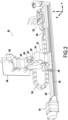
- the optical reading device 30 is mounted on a mobile carriage 32.
- This mobile carriage 32 is motorized and its movements are automatically controlled by the machine 10 to bring the reading device 30 into different positions. At least some of these positions correspond to an analysis zone.
- the mobile carriage 32 is mobile only in one direction, in this case the transverse direction Y of the machine 10 to be able to be brought into positions, in the transverse direction, corresponding to the transverse position of different analysis zones 26' coinciding with the rear receptacles of the analysis strips 22 likely to be engaged in the machine 10.
- the mobile carriage 32 is likely to be brought into as many different positions as there are different analysis zones 26' in the machine.
- the mobile carriage 32 comprises a frame 34 which, at its lower end, cooperates with a slide 36 which ensures the guidance of the mobile carriage 32 in the transverse direction Y. Furthermore, the lower end of the frame 34 is provided with a nut system 38 which cooperates with a drive screw 40 extending along a transverse axis.
- the drive screw 40 is controlled in rotation by an electric motor 42. It is therefore understood that the adequate control of the electric motor 42 in one direction of rotation or the other will cause, by means of the screw/nut system formed by the drive screw 40 and the nut 38 linked to the carriage 32, the movement of the carriage 32 in the transverse direction, in one direction or another.
- a system for detecting the position of the carriage which may be based for example on the information provided by a rotary encoder associated with the motor 42 or on the information provided by sensors arranged on the path of the movable carriage 32, may advantageously be provided to know the position of the movable carriage 32 along the slide 36.
- the slide 36 is fixed in the machine, and the motor 42 and the screw 40 are also fixed in the machine except for their rotational movement on themselves.
- the electric motor 42 controls the movement of the carriage 32.
- the electric motor 42 is itself controlled by a central control unit of the machine 10. Of course, other means of moving the movable carriage could be provided.
- the mobile carriage could move on a linear path as in the exemplary embodiment, or on a curved path or even have the capacity to be moved in two directions, in a plane, or even in three directions in space.
- the control means ensuring the movement of the carriage could comprise other actuators and/or other mechanisms for transforming the movement of the actuator into a movement of the carriage.
- the chassis 34 of the mobile carriage comprises a work area provided with two surfaces inclined relative to each other, both extending in a transverse direction.
- a first work surface 40 horizontal in the embodiment, is provided with a first window 42.
- a second work surface 44 containing the transverse direction but inclined relative to the longitudinal direction, has a second window 46.
- These two work surfaces are intended to be brought opposite an analysis area 26' so that the reading device can, through one of the windows, emit electromagnetic excitation radiation, for example optical radiation in the visible, ultraviolet, or infrared range, in the direction of the analysis area 26', and collect the optical response of the analysis area 26', through the other window.
- the carriage 32 carries both a source of excitation electromagnetic radiation and a photoelectric receiver.
- the carriage 32 comprises an electronic card 48 ensuring in particular at least in part the control and signal processing of the source of electromagnetic radiation and the photoelectric receiver.
- This electronic card 48 is mobile with the carriage 32 and the electrical signals useful to the card 48 are transmitted to a central control unit of the machine by an electrical harness 50 which preferably comprises at least one flexible part, therefore reversibly deformable, to allow the movements of the carriage.
- This beam 50 is for example connected to a fixed terminal block of the machine 10. In the example illustrated, it is received in a rolling guide 54 with articulated links to guide its deformation during movements of the carriage, thus preventing the beam from interfering in the movement mechanism of the carriage. It should also be noted that the mobile carriage 32 can also carry other devices such as for example an optical barcode reader 56. Preferably, the electronic card 48 outputs digital electrical signals. Thus, the electrical signals which are transmitted in the electrical beam 50 in digital form are much less sensitive than analog signals to the disturbances which can be generated around this beam.
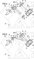
- a first embodiment of a reading device on board a mobile cart 32 is illustrated in the figure 4 .
- a source of electromagnetic radiation 58 intended to excite the optical agent present in the final reaction solution contained in the analysis zone 26'.
- FIG 4 we have also illustrated the presence of a receptacle rear 26 of a strip 22 coinciding with an analysis zone 26', in a relative working position with respect to the reading device 30 which allows the latter both to excite the optical agent and to detect its optical response.
- the reading device 30 comprises a source of electromagnetic radiation which, in this embodiment, is fixed to the frame 34 of the mobile carriage 32, below the first working surface 42. It can advantageously be oriented so as to emit an excitation electromagnetic radiation towards the analysis zone 26' through the first window 42.
- an optical guiding device such as an optical fiber, one or more mirrors, one or more prisms, etc. can be used to guide the radiation from the source 58 towards the first window 42, in which case the source 58 could be arranged differently on the mobile carriage, for example by being mounted on the electronic card 48.
- the source of electromagnetic radiation can be a source of radiation in the optical domain, that is to say radiation whose wavelength is between 10 nm and 1 mm, including in particular ultraviolet radiation, visible light and infrared radiation.
- the source 58 is a monochromatic source.
- a polychromatic source can be envisaged, having a discrete, or continuous or mixed chromatic spectrum.
- the source 58 can be made up of a single component, for example an incandescent filament, a light-emitting diode, a laser diode, or a fluorescent tube, or be made up of several combined components, of the same type or of different types.
- the radiation from the source 58 can optionally be conditioned by a conditioning system which can comprise, as illustrated in the figure 4 , a chromatic filter 60 (for example high-pass, low-pass, band-pass, and/or polarizing, etc.), a diaphragm (not shown), one or more lenses 62.
- a filter 60 allowing the wavelengths useful for excitation to pass, makes it possible to limit the presence of other wavelengths which could disturb the measurement.
- the conditioning system is preferably carried by the frame 34 and arranged between the source 58 and the first window 42.
- a beam splitter is provided at the window 42 , for example in the form of a partially reflecting parallel-faced plate 63, or a semi-reflecting prism, which samples part of the radiation emitted by the source 58 for a need which will be described later.
- the beam splitter 63 therefore comprises a semi-reflecting plate, with parallel faces, which is arranged at the window 42 between the source 58 and the analysis zone 26'. It extends in a plane which forms an angle of 45° relative to a main direction of incidence I of the electromagnetic radiation emitted by the source 58. As illustrated in the Figures 4 and 5 , the incident radiation emitted by the source 58 illuminates the analysis zone 26'.
- the analysis zone 26' which coincides with the rear receptacle 26 of an analysis strip in the illustrated example, has at least one window for the entry of the incident radiation, made of materials transparent to the radiation of the source 58.
- this window is constituted by a side wall section of the rear receptacle 26 which extends substantially perpendicular to a main direction of incidence I of the electromagnetic radiation emitted by the source 58.
- the shortest optical path between the source of excitation electromagnetic radiation 58 and the analysis zone 26' extends along a straight line, in the sense that the optical conditioning system of the excitation radiation emitted by the source 58 does not cause a change in direction of the optical axis between these two elements.
- This shortest optical path therefore defines a main incident direction I for the excitation electromagnetic radiation emitted by the source 58 in the direction of the analysis zone 26'.
- this main incident direction I is inclined relative to the first working face 40 of the chassis 34 by an angle that can be between 30 and 60 degrees, for example 45°, these values being simply illustrative of the exemplary embodiment.
- This incident main direction I is substantially parallel to the second working surface 44 of the chassis.
- the partially reflecting blade 63 has a semi-reflecting flat surface which is oriented at an angle, for example at 45°, relative to the incident main direction I to allow part of the intensity of the beam to be reflected, for example 50% or less, towards a reference channel, as will be described later, while leaving the other part of the intensity of the beam to be directed towards the analysis zone 26'.
- the spectrometer used in the illustrated embodiment is an optoelectronic component capable of delivering an electronic signal representative of the chromatic spectral decomposition of radiation received by the spectrometer.
- this decomposition is a representation of the distribution of the intensity of each elementary wave as a function of the wavelength of the elementary wave.
- the radiation received by the spectrometer can notably comprise the optical response of the final reaction solution contained in an analysis zone 26', when the latter is illuminated by the electromagnetic excitation radiation emitted by the source 58.
- the spectrometer 64 essentially comprises an input diaphragm 66, a chromatic dispersion element 68 and a photoelectric sensor 70.
- the spectrometer 64 has a field of view corresponding to the portion of space seen by the photoelectric sensor 70 through the chromatic dispersion element 68 and the entrance diaphragm 66.
- the spectrometer 64 is arranged on the chassis 34 in such a way that, for a determined position of the mobile carriage 32, its field of vision, through an optical conditioning system of the receiver, encompasses the corresponding analysis zone 26' in such a way that optical radiation emitted by a final reaction solution contained in the analysis zone 26' is directed by the optical conditioning system of the receiver towards the input diaphragm 66 of the spectrometer in an appropriate direction.
- the optical conditioning system of the receiver can be carried by the chassis 34 and be arranged between the spectrometer and the second window 46.
- the chromatic dispersion element 68 causes chromatic dispersion of an incident beam, in the sense that a polychromatic incident beam, for example a parallel beam, sees, by interaction with the chromatic dispersion element, its different chromatic components are deflected from their trajectory by an angle which is dependent on the wavelength of the chromatic component considered.
- a chromatic dispersion element 68 may comprise a diffraction grating.
- a diffraction grating may in particular comprise a series of parallel slits (transmission grating), or reflective stripes (reflection grating). These slits or stripes are spaced regularly, the spacing being called the “pitch” of the grating.
- a chromatic dispersion element 68 could also be produced in the form of one or more diopters, for example by using a refraction prism, in which the chromatic dispersion is obtained by refraction, or even in the form of a combination of one or more diopters and one or more diffraction gratings.
- the diffraction grating is here represented as part of a concave reflection surface returning the scattered radiation towards the photoelectric sensor, which allows for greater compactness of the spectrometer.
- the shortest optical path between the analysis zone 26' and the input diaphragm 68 of the spectrometer 64 extends along a straight line, in the sense that the optical conditioning system of the optical response does not cause a change in direction of the optical axis.
- This shortest optical path therefore defines a main return direction R of the optical response from the analysis zone 26 ' to the spectrometer 64.
- this main return direction R is perpendicular to the second working surface 44 of the chassis.
- the main direction of incidence I taken in the direction going from the source 58 to the analysis zone 26'
- the main return direction R taken in the direction going from the analysis zone 26' to the spectrometer 64 are not both parallel and in the same direction.
- they form a minimal angle between them, for example of at least 45°, with the convention that parallel directions taken in opposite directions form an angle of 180° between them.
- the main direction of incidence I and the main return direction R are perpendicular, which makes it possible to limit the risks of interference of the light response by the incident radiation.
- the main direction of incidence I, taken in the direction going from the source 58 towards the analysis zone 26', and the main return direction R, taken in the direction going from the analysis zone 26' towards the spectrometer 64, could be parallel or almost parallel, but in opposite directions, with the source 58 and the spectrometer arranged on the same side of the analysis zone 26'.
- the rear receptacle 26 has an output window for the optical response which extends substantially perpendicular to the main return direction R.
- the dispersion element 68 and the photoelectric sensor 70 are arranged inside a housing 76 in which the input diaphragm 66 is formed.
- spectrometer 64 of small dimensions.
- Different versions of spectrometers usable in the context of the invention are proposed for example by the Japanese company HAMAMATSU PHOTONICS KK, 325-6, Sunayama-cho, Naka-ku, Hamamatsu City, Shizuoka Pref., 430-8587, Japan.
- one of the spectrometers of the “Mini-Spectrometer” range such as the reference C10988MA-01
- Micro-Spectrometer such as the reference C12666MA, or the reference C12880MA.
- the housing 76 is a parallelepiped housing which comprises a front wall 78 facing towards the second window 46 and oriented substantially perpendicular to a main direction of entry of the radiation into the spectrometer.
- the front wall 78 is provided, substantially at its center, with the entry diaphragm 66 here produced in the form of a slot.
- the concave reflection surface carrying the diffraction grating 68 returns an incident beam, in the form of a chromatic dispersion, towards the photoelectric sensor 70 which is arranged against the internal face of the front wall 78.
- the photoelectric sensor 70 is thus offset laterally relative to the entrance slit 66 and its sensitive surface is turned towards the rear of the housing 76, opposite the reflection surface carrying the diffraction grating 68.
- Such a construction has the advantage of being very compact, allowing such a spectrometer to be contained in a housing 76 whose volume may be less than 10 cm3.
- the spectrometer 64 delivers an electronic signal representative of the chromatic spectral decomposition of the radiation entering through the input diaphragm 66.
- This electronic signal is produced by an electronic circuit associated with the photoelectric sensor 70.
- the electronic circuit can be integrated into the housing 76, attached to it, or be at least partly carried by the electronic card 48 linked to the mobile carriage 34.
- This electronic signal can comprise an analog signal, but it preferably comprises a digital signal less sensitive to disturbances. This signal can be entirely digital. It is advantageously transmitted to the central control unit of the machine by the electrical harness 50.
- the spectrometer is capable of delivering a chromatic spectral decomposition of the optical response over at least one useful range of wavelengths extending between a first wavelength and a second wavelength twice the first.
- a useful range of wavelengths may extend between two wavelengths ⁇ min and ⁇ max , with ⁇ max ⁇ 2 x ⁇ min .
- the use of a spectrometer on board the mobile carriage 34 makes it possible to obtain information on the composition of the spectrum of the optical response. The analysis of this information over a certain significant range makes it possible, as will be seen later, to refine the results of the analysis.
- the useful range of the spectrometer is chosen to correspond to the particular optical properties of the optical agent that one wishes to detect in the final reaction solution.
- the useful range of the spectrometer 64 will be such that it can cover two distinct predetermined optical properties, in particular two distinct wavelengths, each corresponding to at least 2 distinct optical agents, or even more than 2 distinct optical agents.
- reaction solution comprises at least one fluorescent agent whose presence and/or quantity in the reaction solution depends on the presence and/or quantity of an analyte sought in the sample.
- care is then taken to ensure that the emission spectrum of the fluorescent agent is at least partially included in the useful wavelength range of the spectrometer.
- the excitation electromagnetic radiation emitted by the radiation source 58 has a spectrum that is distinct from the emission spectrum of the optical agent sought.
- the two spectra are disjoint in the sense that each of them is contained in a wavelength range and that the two wavelength ranges do not overlap. This makes it possible in particular to further limit the risk of interference of the light response by the excitation radiation.
- the optical reading device may also include means for detecting the intensity of the radiation emitted by the radiation source.
- These means may include a circuit or algorithm for estimating the intensity emitted by the source 58 as a function, for example, of the control parameters of the source 58 and of known characteristics of the source.
- these means may include a photoelectric detector measuring the effective intensity of the excitation radiation emitted by the source 58.
- the means for detecting the intensity of the radiation emitted by the excitation radiation source 58 include a secondary photoelectric sensor 80, distinct from the spectrometer 64.
- the secondary photoelectric sensor 80 is for example a photodiode.
- the secondary photoelectric sensor 80 is sensitive to the wavelength or for the range of wavelengths emitted by the source 58.
- the optical reading device comprises an excitation radiation guidance system which guides a portion of the incident radiation towards the secondary photoelectric sensor, without passing through the analysis zone.
- this guidance system comprises for example the beam splitter, for example in the form of a semi-reflecting blade with parallel faces 63, which directs a part of the radiation emitted by the source 58 towards the secondary sensor 80. This part of the emitted radiation, which is separated by the beam splitter 63, will be designated as being the reference beam.
- the guidance system may comprise a filter 82 and/or for example one or more lenses, or even one or more elements among optical fibers, prisms, mirrors and/or an optical guide of truncated cone shape, as illustrated in figure 4 downstream of filter 82, to route the reference beam to the secondary sensor 80.
- the reference beam does not pass through the analysis zone 26' in its path between the source 58 and the secondary sensor 80.
- the secondary sensor 80 is capable of delivering information, for example in the form of a reference electrical signal, which is an image of the intensity of the radiation emitted by the source 58.
- FIG 5 It has been illustrated on the figure 5 a second embodiment of a reading device used in the invention, which is identical in all respects to the first embodiment illustrated in figure 4 , except as regards the means for detecting the intensity of the radiation emitted by the source 58, and the possible presence of a filter 72 on the trajectory of the light response.
- these means for detecting the intensity of the radiation emitted by the source 58 do not use a secondary sensor separate from the spectrometer 64 but use the spectrometer 64 to detect the intensity of the radiation emitted by the source 58.
- the detection means comprise a system for guiding the reference beam which is taken by the beam splitter 63.
- the guiding system may comprise elements identical or similar to those which were mentioned for the guiding system in the previous embodiment.
- the guiding system conducts the reference beam to the input diaphragm 66 of the spectrometer 64.
- This embodiment is advantageous in that it does not require a separate optoelectronic component for detecting the intensity of the electromagnetic signal emitted by the source 58.
- the system for guiding the reference beam in this second embodiment, also ensures that the reference beam does not pass through the analysis zone 26'. Furthermore, in the example illustrated, the reference beam does not pass through a filter after its reflection by the beam splitter 63.
- This second embodiment is particularly advantageous in the case where the emission spectrum of the source 58 is distinct, preferably disjoint, from the characteristic optical property of the optical agent that one wishes to detect. Indeed, in this case, the spectral decomposition information provided by the spectrometer 64 will make it possible to very clearly and distinctly identify the intensity peak(s) corresponding to distinct wavelengths for, on the one hand, the radiation emitted by the source 58 and, on the other hand, the radiation corresponding to the optical response of the final reaction solution analyzed.
- the reference beam is mixed with the optical response coming from the analysis zone before entering through the diaphragm 66 of the spectrometer 64.
- this second embodiment it could also be provided to alternately route only one or the other of the reference beam or the light response to the spectrometer 64, by obscuring the other.
- the spectrometer 64 successively determines the intensity of the reference beam then the chromatic spectral decomposition of the optical response of the analysis zone 26'.
- This variant which retains the advantage of a single photoelectric sensor, can be useful in the event of at least partial overlap of the spectrum of the excitation radiation emitted by the source 58 with the spectrum of the optical response of the analysis zone 26'.
- an optical filter 72 may optionally be provided on the path of the light response.
- a filter allows the wavelengths of the useful range of the spectrometer to pass, necessary for the detection of the optical agents sought.
- the absence of a filter on the path of the light response would however allow the system to operate with different optical agents which emit different wavelengths, without requiring physical adaptation.
- the presence of a filter on the path of the reference beam is possible, but optional.
- the absence of such a filter, as illustrated in FIG. figure 5 allows the system to operate with 58 sources of different wavelengths, without requiring physical adaptation of the system.
- the fluorescent optical agent emits radiation having a defined wavelength or a defined narrow range of wavelengths or having a spectral decomposition exhibiting one or more characteristic peaks in a defined range of wavelengths.
- the spectrometer 64 has a useful range covering this wavelength or this range of wavelengths corresponding to the fluorescent agent.
- the fluorescent agent is chosen so that its fluorescence is triggered by the excitation of radiation whose wavelength is different from the fluorescence wavelength or wavelength range.
- the invention can be used in an application using a fluorescent agent commonly known as 4-MU (4-methylumbelliferone) which is capable of being excited by radiation in the ultraviolet region, for example by radiation having a wavelength of 370 nm (+/- 5 nm), and which emits fluorescence radiation in a wavelength range whose peak is located at about 450 nm (but whose radiation range can extend from about 375 to 550 nm).
- a fluorescent agent is "QuantaBlu ® ", available from Thermo Fisher Scientific, Pierce Biotechnology, PO Box 117, Rockford, IL 61105 United States, which has a fluorescence emission peak at 420 nm when excited with excitation radiation at 325 nm.
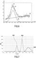
- the chromatic spectral decomposition delivered by the spectrometer 64 has been illustrated in the case where a solution containing a fluorescent agent 4-MU has been placed in an analysis zone 26' , this analysis zone being illuminated by the excitation radiation source 58 consisting in the present case of a light-emitting diode in the ultraviolet range emitting in particular in a narrow wavelength range of 370 nm +/- 5 nm.
- the graph of the figure 6 gives, on the ordinate, an image quantity of an intensity of a chromatic component of the radiation, as a function, along the abscissa axis, of the wavelength LO of the chromatic component of the radiation received by the spectrometer 64.
- the signal delivered by the spectrometer 64 is an irregular S signal.
- this signal has a general shape which clearly has an intensity peak whose maximum is reached at around 450 nm wavelength.
- the intensity peak which extends approximately from 350 to 550 nm, the signal S is not zero. This non-zero part of the signal indicates disturbances or parasitic elements which are not directly linked to the fluorescence of the fluorescent agent.
- a second aspect of the invention therefore consists in proposing a method making it possible to better isolate the interesting characteristic of the signal delivered by the spectrometer, a characteristic which effectively corresponds to the optical property characteristic of the optical agent which one wishes to detect and/or quantify.
- a method for refining the result obtained by an analysis.
- Such a method may be used for the automated in vitro detection and/or quantification of analytes contained in samples. It may advantageously be implemented using a machine according to the invention.
- the sample can be placed in a situation to react with one or more reagents to directly or indirectly produce a reaction solution comprising, in the presence of a determined analyte in the sample, an agent having at least one predetermined optical property, for example a color, a phosphorescence, a luminescence.
- the optical agent is present in the reaction solution or has the predetermined optical property only in the presence of the determined analyte.
- the intensity of the predetermined optical property is a function of the quantity or concentration of the analyte in the determined sample.
- this predetermined optical property is detectable by analysis of a chromatic spectral decomposition of radiation emitted by the reaction solution when this radiation is subjected to incident electromagnetic radiation.
- the optical agent is for example a fluorescent agent and the predetermined optical property is then the fluorescent emission, which can for example be characterized by a particular chromatic spectral decomposition.
- This step can be implemented in the machine as described above or can be done in another machine or manually or by any other means.
- the method provides for illuminating the reaction solution with an excitation electromagnetic radiation.
- the reaction solution is arranged in an analysis zone, coinciding for example with the rear receptacle 26 of an analysis strip 22 as described above.
- the illumination can be carried out by the source 58 of the machine described above.
- the method provides for detecting the optical response of the reaction solution and deducing from the optical response the presence and/or quantification of the analyte.
- the detection of the optical response is done using the machine described above and in particular by interpretation of the chromatic spectral decomposition of the optical response which is obtained using the spectrometer 64.
- an approximate theoretical relationship of variation of the intensity as a function of the wavelength is determined, an image of the chromatic spectral decomposition of the optical response.
- a part T1 which best corresponds to the intensity peak extending between approximately 350 and 550 nanometers.
- This part T1 can be predefined as a polynomial curve or a Gaussian curve or any other parametric curve, and it is then possible, by known regression methods, to determine the part T1 of the theoretical relationship.
- a part T2 of the theoretical relationship is a linear relationship which best corresponds to the signal S outside the peak intensity ranging between 350 and 550 nanometers. This T2 part of the theoretical relationship can be determined for example by linear regression.
- a linear shift of intensity affects the entire curve.
- this linear shift can be assimilated to the linear part T2 of the theoretical relationship.
- this linear shift can be linked for example at least in part to a differential absorption of radiation by the material constituting the rear receptacle 26 of the analysis bar 22.
- a corrected theoretical relationship for the variation of intensity as a function of wavelength by correcting the approximate theoretical relationship as a function of the linear shift. For example, one can simply subtract point by point the linear shift from the approximate theoretical relationship. By this subtraction, one thus arrives at a corrected TC curve, which can be assimilated to the part of the optical response purely linked to the characteristic property of the optical agent, for example its fluorescence property.
- the chromatic spectral decomposition obtained in this method which is made possible by the use of a spectrometer in the machine according to the invention, makes it possible to use measurement values of the optical response, outside the wavelength range of the characteristic property of the optical agent, to refine the detection in the wavelength range of the characteristic property of the optical agent.
- the known machines implement methods in which, within the same analysis strip, only one analysis can be carried out due to the detection of a single optical agent in a given final reaction solution contained in a given analysis zone.
- a new method is proposed which makes it possible, within the framework of the same analysis, to obtain more information.
- This method can be implemented using a machine according to the invention as described above, using a spectrometer.
- This new method uses one or more reagents to directly or indirectly produce a reaction solution comprising at least two distinct optical agents each having at least one predetermined optical property (color, fluorescence, phosphorescence, ..., as defined above), the two predetermined optical properties, each corresponding to an optical agent, being distinct.
- the two optical agents can have a different color, a different fluorescence, a different phosphorescence, ... all properties which can be distinguished by their chromatic spectral decomposition.
- the method comprises the steps of acquiring a chromatic spectral decomposition of the optical response, and separately detecting the two distinct predetermined optical properties in said spectral decomposition.
- the method provides for acquiring a single spectral decomposition, under a given incident electromagnetic radiation.
- the optical properties will be detected separately in the sense that they can each be identified in the same spectral decomposition.
- each optical property may result in the presence of an intensity peak having a maximum for a different wavelength.
- the intensity peaks will preferably correspond to distinct wavelength ranges, more preferably disjoint.
- the method provides for acquiring several chromatic spectral decompositions, acquired by illuminating the analysis area with different incident electromagnetic radiation (in particular different by their chromatic spectral decomposition).
- the distinct predetermined optical properties will be detected separately in the sense that they can each be identified in distinct chromatic spectral decompositions.
- the step of detecting a predetermined optical property can be accomplished by detecting the absence of that predetermined optical property.
- This method can be implemented to detect the presence of at least two distinct analytes in the sample.
- the different optical agents correspond to distinct analytes. It can also be implemented to detect at least two distinct reactions involving the same analyte. In this case, the different optical agents correspond to distinct reactions for the same analyte.
- the step of acquiring a chromatic spectral decomposition of the optical response comprises a step of chromatic dispersion of an optical beam from the optical response and a step of detecting the intensity by components of distinct wavelengths of the beam thus dispersed.
- each of the above methods may include a step of detecting the intensity of the radiation emitted by the radiation source.
- This step may include a step of guiding a portion of the incident radiation, without passing through the analysis zone, and a step consisting of acquiring a chromatic spectral decomposition of said portion of the incident radiation forming a reference beam, in particular using a spectrometer, as implemented in the device illustrated in FIG. figure 5 .
- a step of mixing said part of the incident radiation and the optical response of the reaction solution can be provided, for example as implemented in the device illustrated in figure 5 .
- the invention may be improved by using a method and system as described in the document WO2013/045807 A1 .
- a system and method for modulating the source and demodulating the detection and reference signals are described, with the aim of improving the signal-to-noise ratio of the detection measurement.
- the system and method are described in the document WO2013/045807 A1 in the context where there is only one detection signal.
- the same modulation and detection principle can be applied in the context of the invention. It is thus possible to modulate the radiation source 58 in amplitude at a carrier frequency/wavelength.
- the output signal of the spectrometer analog or digital, which covers a useful range of wavelengths, into a series of N elementary signals which are each representative of the intensity of the signal collected by the spectrometer for an elementary wavelength or elementary range of wavelengths.
- the N elementary wavelengths or elementary ranges of wavelengths cover the useful range of wavelengths, preferably continuously or quasi-continuously.
- the result is a chromatic spectral decomposition of the optical response which presents a better signal/noise ratio, that is to say a decomposition less disturbed by the ambient noise during the measurement.
- the following presents an experiment showing the ability of a machine and a method according to the invention to acquire, in a single acquisition, the light response corresponding to three optical agents, with the ability to quantify the presence of each optical agent.
- the light source used is a monochromatic source emitting in the ultraviolet (370 nm +/- 5nm) to excite the molecules
- Solutions of agents A, B, and C were prepared using CHES (N-Cyclohexyl-2-aminoethanesulfonic acid) buffering agent, with a pH of 9.2.
- CHES N-Cyclohexyl-2-aminoethanesulfonic acid
- Agent C 200 nM Floor 1 Agent C 200 nM Floor 2 Agent A 20 nM Floor 3 Agent A 200 nM Floor 4 Agent B 20nM Sol 5 Agent A 20nM Agent B 20nM Agent C 200nM
- a volume of 250 microliters of each solution was placed in an analysis zone and the light response of each solution was acquired using a machine according to the invention.
- the optimization process used is the one available by the Matlab software and using the algorithm called “Flexible Simplex Method".
- This algorithm minimizes the cost function which is the quadratic sum of the errors, representing the error between the model (with the instantaneous values of the vector parameters for the iteration considered) and the experimental curve.
- the vector P is modified according to the algorithm and the quadratic sum of the errors is verified. The iterations are stopped when we reach an error lower than a given threshold which depends on the desired precision.
- the initial parameter values, used for the optimization process, are: A1 0 ⁇ 1 0 ⁇ 1 0 A2 0 ⁇ 2 0 ⁇ 2 0 A3 0 ⁇ 3 0 ⁇ 3 0 1000 525 21270 170 605 30270 1000 705 15270
- the three functions G525, G605 and G705 defined with these optimized parameters make it possible to extract from the overall light response illustrated in figure 8 the light responses due individually to each optical agent. By referring to an adequate calibration scale, one can easily quantify the concentration of each optical agent in the single solution analyzed.
- FIG 10 illustrates the three functions G525, G605 and G705 obtained with these parameters superimposed with the curve of the figure 8 .
- the curves are expressed in units of relative intensity RU of the light response, as a function of the wavelength ⁇ in nm.
- This experiment shows how a machine and/or a method according to the invention can be implemented to quantify, in a single analysis, the presence of several distinct optical agents which can indicate several analytical reactions.
Landscapes
- Physics & Mathematics (AREA)
- Health & Medical Sciences (AREA)
- Life Sciences & Earth Sciences (AREA)
- Chemical & Material Sciences (AREA)
- Immunology (AREA)
- General Health & Medical Sciences (AREA)
- Pathology (AREA)
- General Physics & Mathematics (AREA)
- Biochemistry (AREA)
- Analytical Chemistry (AREA)
- Engineering & Computer Science (AREA)
- Spectroscopy & Molecular Physics (AREA)
- Nuclear Medicine, Radiotherapy & Molecular Imaging (AREA)
- Hematology (AREA)
- Biomedical Technology (AREA)
- Molecular Biology (AREA)
- Chemical Kinetics & Catalysis (AREA)
- Mathematical Physics (AREA)
- Theoretical Computer Science (AREA)
- Urology & Nephrology (AREA)
- Optics & Photonics (AREA)
- Medical Informatics (AREA)
- Public Health (AREA)
- Cell Biology (AREA)
- Food Science & Technology (AREA)
- Biotechnology (AREA)
- Biophysics (AREA)
- Heart & Thoracic Surgery (AREA)
- Medicinal Chemistry (AREA)
- Microbiology (AREA)
- Surgery (AREA)
- Animal Behavior & Ethology (AREA)
- Veterinary Medicine (AREA)
- Plasma & Fusion (AREA)
- Investigating, Analyzing Materials By Fluorescence Or Luminescence (AREA)
- Investigating Or Analysing Materials By The Use Of Chemical Reactions (AREA)
- Automatic Analysis And Handling Materials Therefor (AREA)
- Investigating Or Analysing Materials By Optical Means (AREA)
- Investigating Or Analysing Biological Materials (AREA)
Claims (9)
- Verfahren zur automatisierten In-vitro-Detektion und/oder -Quantifizierung von in Proben enthaltenen Analyten, umfassend die folgenden Schritte:- Versetzen der Probe in die Situation, mit ein oder mehreren Reagenzien zu reagieren, um direkt oder indirekt eine Reaktionslösung zu erzeugen, die, bei Vorkommen eines bestimmten Analyten in der Probe, ein optisches Mittel umfasst, das mindestens eine vorbestimmte optische Eigenschaft besitzt;- Beleuchten der in einem optischen Analysebereich enthaltenen Reaktionslösung mit einer einfallenden elektromagnetischen Strahlung;- Detektieren der optischen Antwort der Reaktionslösung;- Ableiten des Vorkommens und/oder der Quantifizierung des Analyten aus der optischen Antwort;wobei das Verfahren ein oder mehrere Reagenzien einsetzt, um direkt oder indirekt eine Reaktionslösung zu erzeugen, die mindestens zwei verschiedene optische Mittel umfasst, von denen jedes mindestens eine vorbestimmte optische Eigenschaft besitzt, wobei die beiden vorbestimmten optischen Eigenschaften verschieden sind,wobei das Verfahren ferner die Schritte umfasst, die darin bestehen:- eine chromatische spektrale Zerlegung der optischen Antwort zu erfassen und- die beiden verschiedenen vorbestimmten optischen Eigenschaften in der spektralen Zerlegung getrennt zu detektieren,wobei das Verfahren dadurch gekennzeichnet ist, dass es umfasst:- einen Schritt des Führens eines Teils der einfallenden elektromagnetischen Strahlung, ohne durch den optischen Analysebereich zu verlaufen,- einen Schritt, der darin besteht, eine chromatische spektrale Zerlegung des Teils der einfallenden Strahlung zu erfassen,- vor dem Schritt, der darin besteht, eine chromatische spektrale Zerlegung der einfallenden elektromagnetischen Strahlung zu erfassen, einen Schritt des Mischens des Teils der einfallenden elektromagnetischen Strahlung und der optischen Antwort der Reaktionslösung,- einen Schritt der Detektion der Intensität des spektral zerlegten Teils der einfallenden elektromagnetischen Strahlung.
- Verfahren nach Anspruch 1, dadurch gekennzeichnet, dass der Schritt, der darin besteht, eine chromatische spektrale Zerlegung der optischen Antwort zu erfassen, einen Schritt der chromatischen Dispersion eines aus der optischen Antwort hervorgehenden optischen Strahls und der Detektion der Intensität durch verschiedene Wellenlängenkomponenten des so dispergierten Strahls umfasst.
- Gerät zur automatisierten In-vitro-Detektion und/oder -Quantifizierung von in Proben enthaltenen Analyten, umfassend:- mehrere optische Analysebereiche (26'), die dazu bestimmt sind, jeweils eine Reaktionslösung aufzunehmen, die durch Reaktion mit der Probe erhalten wird, und- eine optische Lesevorrichtung (30), die in der Lage ist, eine optische Antwort der Reaktionslösung auf eine elektromagnetische Anregung zu detektieren und/oder zu quantifizieren, wobei die optische Lesevorrichtung mindestens eine Quelle elektromagnetischer Strahlung (58) umfasst, die in der Lage ist, einen der optischen Analysebereiche (26') zu beleuchten,- einen fotoelektrischen Sensor (70), der dazu ausgebildet ist, eine optische Strahlung aufzunehmen, die aus der in dem optischen Analysebereich enthaltenen Reaktionslösung stammt, und in der Lage ist, die optische Antwort der Reaktionslösung zu detektieren, und- ein Spektrometer (64), das in der Lage ist, eine chromatische spektrale Zerlegung der optischen Antwort auszugeben, wobei der fotoelektrische Sensor (70) zu dem Spektrometer (64) gehört,wobei das Gerät dadurch gekennzeichnet ist, dass die Lesevorrichtung (30) von einem beweglichen Schlitten (32) des Geräts getragen wird, der motorbetrieben ist und dessen Bewegungen automatisch gesteuert werden, um die Lesevorrichtung (30) in unterschiedliche Positionen zu bringen, die jeweils einem Analysebereich (26') entsprechen,und dadurch, dass die optische Lesevorrichtung (30) Einrichtungen zur Detektion der Intensität einer von der Strahlungsquelle ausgesendeten einfallenden Strahlung umfasst, wobei die Einrichtungen zur Detektion der von der Strahlungsquelle (58) ausgesendeten einfallenden Strahlung das Spektrometer (64) beinhalten und ein Führungssystem (63), das so konfiguriert ist, dass es einen Teil der einfallenden Strahlung zum Spektrometer leitet, ohne durch die optische Analysezone (26') zu gehen, und das so konfiguriert ist, dass es den Teil der einfallenden Strahlung und die optische Reaktion der Reaktionslösung mischt...
- Gerät nach Anspruch 3, wobei das Spektrometer (64) in der Lage ist, eine chromatische spektrale Zerlegung der optischen Antwort über mindestens einen Nutzwellenlängenbereich zwischen zwei Wellenlängen λmin und λmax mit λmax > 2 x λmin auszugeben.
- Gerät nach einem der Ansprüche 3 oder 4, wobei das Spektrometer (64) ein Element zur chromatischen Dispersion (68) umfasst und der fotoelektrische Sensor (70) linear oder zweidimensional ist.
- Gerät nach einem der Ansprüche 3 bis 5, wobei das Spektrometer (64) einen elektronischen Schaltkreis umfasst, der an den fotoelektrischen Sensor (70) angeschlossen ist und der ein elektrisches Signal ausgibt, das ein Abbild der chromatischen spektralen Zerlegung der optischen Antwort ist.
- Gerät nach Anspruch 6, wobei das elektrische Abbildsignal ein analoges Signal ist.
- Gerät nach einem der Ansprüche 3 bis 7, wobei die Strahlungsquelle eine monochromatische Quelle ist.
- Gerät nach einem der Ansprüche 3 bis 7, wobei die Strahlungsquelle eine polychromatische Quelle ist.
Applications Claiming Priority (2)
| Application Number | Priority Date | Filing Date | Title |
|---|---|---|---|
| FR1553912A FR3035716B1 (fr) | 2015-04-30 | 2015-04-30 | Machine et procede pour la detection automatisee in vitro d'analytes mettant en oeuvre une decomposition spectrale chromatique d'une reponse optique |
| PCT/FR2016/050996 WO2016174356A2 (fr) | 2015-04-30 | 2016-04-28 | Machine et procede pour la detection automatisee in vitro d'analytes mettant en œuvre une decomposition spectrale chromatique d'une reponse optique |
Publications (2)
| Publication Number | Publication Date |
|---|---|
| EP3289334A2 EP3289334A2 (de) | 2018-03-07 |
| EP3289334B1 true EP3289334B1 (de) | 2025-03-05 |
Family
ID=53794350
Family Applications (1)
| Application Number | Title | Priority Date | Filing Date |
|---|---|---|---|
| EP16724687.5A Active EP3289334B1 (de) | 2015-04-30 | 2016-04-28 | Vorrichtung und verfahren zum automatischen in-vitro-nachweis von analyten anhand einer spektralen zerlegung einer optischen antwort |
Country Status (6)
| Country | Link |
|---|---|
| US (1) | US10753926B2 (de) |
| EP (1) | EP3289334B1 (de) |
| JP (2) | JP7117849B2 (de) |
| CN (1) | CN107533007B (de) |
| FR (1) | FR3035716B1 (de) |
| WO (1) | WO2016174356A2 (de) |
Families Citing this family (12)
| Publication number | Priority date | Publication date | Assignee | Title |
|---|---|---|---|---|
| CN108593568A (zh) * | 2018-05-02 | 2018-09-28 | 上海锆仪电子科技有限公司 | 自动化定性和定量物质检测方法、装置及其系统 |
| CN108593555A (zh) * | 2018-07-04 | 2018-09-28 | 河南农业大学 | 多通道吸收光谱检测台及检测系统 |
| TWI748164B (zh) * | 2019-02-15 | 2021-12-01 | 柯正浩 | 篩檢試紙讀取系統 |
| KR20220044818A (ko) * | 2019-08-12 | 2022-04-11 | 에이엠에스 아게 | 화학 물질들의 검출을 위한 통합 센서 모듈들 |
| IT202000017836A1 (it) * | 2020-07-23 | 2022-01-23 | Fameccanica Data Spa | Procedimento e apparecchio per l’analisi in linea di un prodotto composito in una macchina per la produzione di articoli sanitari assorbenti |
| JP1679420S (de) * | 2020-07-28 | 2021-06-14 | ||
| JP1679419S (de) * | 2020-07-28 | 2021-06-14 | ||
| JP1683264S (de) * | 2020-07-28 | 2021-08-10 | ||
| JP1683948S (de) * | 2020-07-28 | 2021-08-23 | ||
| EP4012610A1 (de) * | 2020-12-11 | 2022-06-15 | Biomerieux | Verfahren zum nachweis des vorhandenseins einer probe und zugehörige vorrichtung |
| USD960739S1 (en) * | 2021-01-22 | 2022-08-16 | Fujifilm Corporation | Optical analyzer |
| KR102742889B1 (ko) * | 2022-03-08 | 2024-12-16 | 주식회사 유진셀 | 검체 검사 장치 및 검체 검사 방법 |
Family Cites Families (32)
| Publication number | Priority date | Publication date | Assignee | Title |
|---|---|---|---|---|
| JPS6182169A (ja) * | 1985-06-12 | 1986-04-25 | Japan Spectroscopic Co | フロ−インジエクシヨン分析法 |
| EP0241268A3 (de) * | 1986-04-11 | 1989-02-08 | Sclavo Inc.West Coast | Fluorimeter mit gepulstem Lichtsystem |
| US4750837A (en) * | 1986-04-11 | 1988-06-14 | Sclavo Inc. | Fluorometer with reference light source |
| US5639668A (en) | 1995-09-14 | 1997-06-17 | Boehringer Mannheim Corporation | Optical apparatus for performing an immunoassay |
| FI954511A0 (fi) | 1995-09-22 | 1995-09-22 | Labsystems Oy | Fluorometer |
| US5757013A (en) | 1995-12-06 | 1998-05-26 | American Research Corporation Of Virginia | Fluorescence decay measurement by calculation of inner product |
| AU715627B2 (en) | 1996-02-21 | 2000-02-03 | Biomerieux Vitek, Inc. | Automatic sample testing machine |
| US5746803A (en) | 1996-06-04 | 1998-05-05 | The Dow Chemical Company | Metallic-carbide group VIII metal powder and preparation methods thereof |
| US6207392B1 (en) | 1997-11-25 | 2001-03-27 | The Regents Of The University Of California | Semiconductor nanocrystal probes for biological applications and process for making and using such probes |
| DE19957682A1 (de) * | 1999-12-01 | 2001-06-07 | Deutsche Telekom Ag | Vorrichtung zur optischen Spektroskopie und Verfahren zu dessen Herstellung |
| JP2001242081A (ja) * | 2000-02-29 | 2001-09-07 | Nikon Corp | Dnaチップ読み取りヘッド及びdnaチップ読み取り装置 |
| AU2001249237A1 (en) * | 2000-03-16 | 2001-09-24 | Spectrumedix Corporation | Multi-wavelength array reader for biological assay |
| GB0121700D0 (en) | 2001-09-07 | 2001-10-31 | Univ Leicester | Detection of fluorescence |
| JP2003240638A (ja) | 2002-02-13 | 2003-08-27 | Nikon Corp | 検査装置 |
| FR2848669B1 (fr) | 2002-12-12 | 2005-09-02 | Commissariat Energie Atomique | Procede de mesure d'une quantite de photons proportionnelle a la quantite de photons recus par l'objet et dispositif associe. |
| JP4021414B2 (ja) * | 2003-11-26 | 2007-12-12 | オリンパス株式会社 | スペクトラルデコンボリューション法及びスペクトラルブラインドデコンボリューション法 |
| WO2006047621A1 (en) | 2004-10-22 | 2006-05-04 | Parallel Synthesis Technologies, Inc. | Rare earth downconverting phosphor compositions for optically encoding objects and methods and apparatus relating to same |
| US7339668B2 (en) * | 2005-10-18 | 2008-03-04 | Thermo Electron Scientific Instruments Llc | Spectrometer for analysis of multiple samples |
| WO2007147169A2 (en) * | 2006-06-16 | 2007-12-21 | Doug Macrae | System and method generating targeted newsletters |
| CA2664133C (en) * | 2006-08-22 | 2012-10-23 | Bayer Healthcare Llc | A method for correcting a spectral image for optical aberrations using software |
| JP2008286562A (ja) | 2007-05-16 | 2008-11-27 | Shimadzu Corp | 蛍光分光光度計 |
| AU2008325237B2 (en) * | 2007-11-05 | 2014-05-01 | Biosensor, Inc. | Optical sensor for determining the concentration of an analyte |
| JP5162049B2 (ja) * | 2008-05-15 | 2013-03-13 | 浜松ホトニクス株式会社 | 分光モジュール及び分光モジュールの製造方法 |
| KR100875180B1 (ko) * | 2008-07-10 | 2008-12-22 | 주식회사 동부하이텍 | 반도체 소자의 제조 방법 |
| US8926906B2 (en) * | 2008-07-21 | 2015-01-06 | Concordia University | Microfluidic device and method for fabricating the microfluidic device |
| DE102009046831B4 (de) * | 2009-11-18 | 2015-02-12 | Fraunhofer-Gesellschaft zur Förderung der angewandten Forschung e.V. | Strahlungserzeugungsvorrichtung zum Erzeugen einer elektromagnetischen Strahlung mit einer einstellbaren spektralen Zusammensetzung und Verfahren zur Herstellung derselben |
| JP5743558B2 (ja) * | 2011-01-12 | 2015-07-01 | 株式会社東芝 | 分析装置 |
| JP2012247188A (ja) | 2011-05-02 | 2012-12-13 | National Institute Of Advanced Industrial & Technology | ナノカーボンを用いた臨床検査 |
| FR2980577B1 (fr) | 2011-09-26 | 2013-09-20 | Biomerieux Sa | Systeme de detection et/ou de quantification in vitro par fluorimetrie |
| US20150226608A1 (en) * | 2012-09-19 | 2015-08-13 | Nec Corporation | Spectroscopic analysis apparatus, spectroscopic analysis method, and computer readable medium |
| US9291503B2 (en) | 2012-11-08 | 2016-03-22 | Hitachi, Ltd. | Flow type single-particle spectrometer |
| EP2853884A1 (de) * | 2013-09-25 | 2015-04-01 | Siemens Aktiengesellschaft | Verfahren zur Bestimmung von Metallen in Ölproben aus Schmieröl von Maschinen |
-
2015
- 2015-04-30 FR FR1553912A patent/FR3035716B1/fr active Active
-
2016
- 2016-04-28 CN CN201680024699.2A patent/CN107533007B/zh active Active
- 2016-04-28 WO PCT/FR2016/050996 patent/WO2016174356A2/fr not_active Ceased
- 2016-04-28 JP JP2017556847A patent/JP7117849B2/ja active Active
- 2016-04-28 EP EP16724687.5A patent/EP3289334B1/de active Active
- 2016-04-28 US US15/567,447 patent/US10753926B2/en active Active
-
2021
- 2021-02-04 JP JP2021016479A patent/JP7511500B2/ja active Active
Also Published As
| Publication number | Publication date |
|---|---|
| US10753926B2 (en) | 2020-08-25 |
| WO2016174356A2 (fr) | 2016-11-03 |
| JP2021099347A (ja) | 2021-07-01 |
| FR3035716A1 (fr) | 2016-11-04 |
| JP2018522209A (ja) | 2018-08-09 |
| WO2016174356A3 (fr) | 2016-12-29 |
| EP3289334A2 (de) | 2018-03-07 |
| US20180106788A1 (en) | 2018-04-19 |
| CN107533007B (zh) | 2024-03-19 |
| JP7511500B2 (ja) | 2024-07-05 |
| FR3035716B1 (fr) | 2019-06-21 |
| JP7117849B2 (ja) | 2022-08-15 |
| CN107533007A (zh) | 2018-01-02 |
Similar Documents
| Publication | Publication Date | Title |
|---|---|---|
| EP3289334B1 (de) | Vorrichtung und verfahren zum automatischen in-vitro-nachweis von analyten anhand einer spektralen zerlegung einer optischen antwort | |
| Morris | Spectrophotometry | |
| CA2862766C (en) | Optical interrogation device | |
| EP3257947B1 (de) | Verfahren und system zur identifizierung des gramtyps einer bakterie | |
| JP6599855B2 (ja) | 変形可能な容器内の物質の濃度を求める方法 | |
| JP5743558B2 (ja) | 分析装置 | |
| EP3054281B1 (de) | Vorrichtung zum messen eines von einer probe rückgestreuten optischen signals | |
| CN101308156A (zh) | 分析装置 | |
| US12000785B2 (en) | Apparatus and method for detecting photoluminescent light emitted from a sample | |
| JPH0989775A (ja) | 分光測定装置及び自動分析装置 | |
| JP7272348B2 (ja) | 微小粒子計測装置 | |
| EP3054282A1 (de) | Verfahren zur charakterisierung einer probe durch messung eines zurückgestrahlten optischen signals | |
| EP2435816B1 (de) | Spektroskopische sonde und verfahren für den nachweis einer inhomogenität | |
| US20040110305A1 (en) | Method of mixing a sample with a reagent in a chemistry | |
| EP3054284A1 (de) | Verfahren zum korrigieren eines von einer probe zurückgestrahlten signals, und entsprechende vorrichtung | |
| WO2010136728A1 (fr) | Dispositif de spectroscopie et procédé pour sa mise en oeuvre | |
| EP2939003B1 (de) | Verfahren und system zur erkennung und messung von fluoreszenzsignalen | |
| CN101317085A (zh) | 具有样品室和光敏元件的生物芯片设备,在生物芯片设备的至少一个样品室内检测荧光粒子的方法 | |
| FR3048777A1 (fr) | Porte-echantillon, de preference pour chimiometrie d'un echantillon sanguin | |
| Kiesel et al. | Compact optical characterization platform for detection of bio-molecules in fluidic and aerosol samples | |
| JP2006220582A (ja) | センシング装置 | |
| Desfours et al. | Innovative Surface Plasmon Resonance biosensing architectures |
Legal Events
| Date | Code | Title | Description |
|---|---|---|---|
| STAA | Information on the status of an ep patent application or granted ep patent |
Free format text: STATUS: THE INTERNATIONAL PUBLICATION HAS BEEN MADE |
|
| PUAI | Public reference made under article 153(3) epc to a published international application that has entered the european phase |
Free format text: ORIGINAL CODE: 0009012 |
|
| STAA | Information on the status of an ep patent application or granted ep patent |
Free format text: STATUS: REQUEST FOR EXAMINATION WAS MADE |
|
| 17P | Request for examination filed |
Effective date: 20171030 |
|
| AK | Designated contracting states |
Kind code of ref document: A2 Designated state(s): AL AT BE BG CH CY CZ DE DK EE ES FI FR GB GR HR HU IE IS IT LI LT LU LV MC MK MT NL NO PL PT RO RS SE SI SK SM TR |
|
| AX | Request for extension of the european patent |
Extension state: BA ME |
|
| DAV | Request for validation of the european patent (deleted) | ||
| DAX | Request for extension of the european patent (deleted) | ||
| STAA | Information on the status of an ep patent application or granted ep patent |
Free format text: STATUS: EXAMINATION IS IN PROGRESS |
|
| 17Q | First examination report despatched |
Effective date: 20210119 |
|
| GRAP | Despatch of communication of intention to grant a patent |
Free format text: ORIGINAL CODE: EPIDOSNIGR1 |
|
| STAA | Information on the status of an ep patent application or granted ep patent |
Free format text: STATUS: GRANT OF PATENT IS INTENDED |
|
| INTG | Intention to grant announced |
Effective date: 20230508 |
|
| GRAJ | Information related to disapproval of communication of intention to grant by the applicant or resumption of examination proceedings by the epo deleted |
Free format text: ORIGINAL CODE: EPIDOSDIGR1 |
|
| STAA | Information on the status of an ep patent application or granted ep patent |
Free format text: STATUS: EXAMINATION IS IN PROGRESS |
|
| INTC | Intention to grant announced (deleted) | ||
| GRAP | Despatch of communication of intention to grant a patent |
Free format text: ORIGINAL CODE: EPIDOSNIGR1 |
|
| STAA | Information on the status of an ep patent application or granted ep patent |
Free format text: STATUS: GRANT OF PATENT IS INTENDED |
|
| INTG | Intention to grant announced |
Effective date: 20240926 |
|
| RAP3 | Party data changed (applicant data changed or rights of an application transferred) |
Owner name: BIOMERIEUX |
|
| GRAS | Grant fee paid |
Free format text: ORIGINAL CODE: EPIDOSNIGR3 |
|
| GRAA | (expected) grant |
Free format text: ORIGINAL CODE: 0009210 |
|
| STAA | Information on the status of an ep patent application or granted ep patent |
Free format text: STATUS: THE PATENT HAS BEEN GRANTED |
|
| AK | Designated contracting states |
Kind code of ref document: B1 Designated state(s): AL AT BE BG CH CY CZ DE DK EE ES FI FR GB GR HR HU IE IS IT LI LT LU LV MC MK MT NL NO PL PT RO RS SE SI SK SM TR |
|
| REG | Reference to a national code |
Ref country code: GB Ref legal event code: FG4D Free format text: NOT ENGLISH |
|
| REG | Reference to a national code |
Ref country code: CH Ref legal event code: EP |
|
| REG | Reference to a national code |
Ref country code: IE Ref legal event code: FG4D Free format text: LANGUAGE OF EP DOCUMENT: FRENCH |
|
| REG | Reference to a national code |
Ref country code: DE Ref legal event code: R096 Ref document number: 602016091441 Country of ref document: DE |
|
| PG25 | Lapsed in a contracting state [announced via postgrant information from national office to epo] |
Ref country code: RS Free format text: LAPSE BECAUSE OF FAILURE TO SUBMIT A TRANSLATION OF THE DESCRIPTION OR TO PAY THE FEE WITHIN THE PRESCRIBED TIME-LIMIT Effective date: 20250605 |
|
| PG25 | Lapsed in a contracting state [announced via postgrant information from national office to epo] |
Ref country code: FI Free format text: LAPSE BECAUSE OF FAILURE TO SUBMIT A TRANSLATION OF THE DESCRIPTION OR TO PAY THE FEE WITHIN THE PRESCRIBED TIME-LIMIT Effective date: 20250305 |
|
| PGFP | Annual fee paid to national office [announced via postgrant information from national office to epo] |
Ref country code: DE Payment date: 20250429 Year of fee payment: 10 |
|
| REG | Reference to a national code |
Ref country code: NL Ref legal event code: MP Effective date: 20250305 |
|
| PG25 | Lapsed in a contracting state [announced via postgrant information from national office to epo] |
Ref country code: ES Free format text: LAPSE BECAUSE OF FAILURE TO SUBMIT A TRANSLATION OF THE DESCRIPTION OR TO PAY THE FEE WITHIN THE PRESCRIBED TIME-LIMIT Effective date: 20250305 |
|
| PGFP | Annual fee paid to national office [announced via postgrant information from national office to epo] |
Ref country code: GB Payment date: 20250428 Year of fee payment: 10 |
|
| REG | Reference to a national code |
Ref country code: LT Ref legal event code: MG9D |
|
| PG25 | Lapsed in a contracting state [announced via postgrant information from national office to epo] |
Ref country code: NO Free format text: LAPSE BECAUSE OF FAILURE TO SUBMIT A TRANSLATION OF THE DESCRIPTION OR TO PAY THE FEE WITHIN THE PRESCRIBED TIME-LIMIT Effective date: 20250605 |
|
| PGFP | Annual fee paid to national office [announced via postgrant information from national office to epo] |
Ref country code: IT Payment date: 20250521 Year of fee payment: 10 |
|
| PG25 | Lapsed in a contracting state [announced via postgrant information from national office to epo] |
Ref country code: HR Free format text: LAPSE BECAUSE OF FAILURE TO SUBMIT A TRANSLATION OF THE DESCRIPTION OR TO PAY THE FEE WITHIN THE PRESCRIBED TIME-LIMIT Effective date: 20250305 |
|
| PG25 | Lapsed in a contracting state [announced via postgrant information from national office to epo] |
Ref country code: LV Free format text: LAPSE BECAUSE OF FAILURE TO SUBMIT A TRANSLATION OF THE DESCRIPTION OR TO PAY THE FEE WITHIN THE PRESCRIBED TIME-LIMIT Effective date: 20250305 |
|
| PGFP | Annual fee paid to national office [announced via postgrant information from national office to epo] |
Ref country code: FR Payment date: 20250425 Year of fee payment: 10 |
|
| PG25 | Lapsed in a contracting state [announced via postgrant information from national office to epo] |
Ref country code: GR Free format text: LAPSE BECAUSE OF FAILURE TO SUBMIT A TRANSLATION OF THE DESCRIPTION OR TO PAY THE FEE WITHIN THE PRESCRIBED TIME-LIMIT Effective date: 20250606 Ref country code: BG Free format text: LAPSE BECAUSE OF FAILURE TO SUBMIT A TRANSLATION OF THE DESCRIPTION OR TO PAY THE FEE WITHIN THE PRESCRIBED TIME-LIMIT Effective date: 20250305 |
|
| REG | Reference to a national code |
Ref country code: AT Ref legal event code: MK05 Ref document number: 1773309 Country of ref document: AT Kind code of ref document: T Effective date: 20250305 |
|
| PG25 | Lapsed in a contracting state [announced via postgrant information from national office to epo] |
Ref country code: NL Free format text: LAPSE BECAUSE OF FAILURE TO SUBMIT A TRANSLATION OF THE DESCRIPTION OR TO PAY THE FEE WITHIN THE PRESCRIBED TIME-LIMIT Effective date: 20250305 |
|
| PG25 | Lapsed in a contracting state [announced via postgrant information from national office to epo] |
Ref country code: SE Free format text: LAPSE BECAUSE OF FAILURE TO SUBMIT A TRANSLATION OF THE DESCRIPTION OR TO PAY THE FEE WITHIN THE PRESCRIBED TIME-LIMIT Effective date: 20250305 |
|
| PG25 | Lapsed in a contracting state [announced via postgrant information from national office to epo] |
Ref country code: SM Free format text: LAPSE BECAUSE OF FAILURE TO SUBMIT A TRANSLATION OF THE DESCRIPTION OR TO PAY THE FEE WITHIN THE PRESCRIBED TIME-LIMIT Effective date: 20250305 |
|
| PG25 | Lapsed in a contracting state [announced via postgrant information from national office to epo] |
Ref country code: PT Free format text: LAPSE BECAUSE OF FAILURE TO SUBMIT A TRANSLATION OF THE DESCRIPTION OR TO PAY THE FEE WITHIN THE PRESCRIBED TIME-LIMIT Effective date: 20250707 |
|
| PG25 | Lapsed in a contracting state [announced via postgrant information from national office to epo] |
Ref country code: PL Free format text: LAPSE BECAUSE OF FAILURE TO SUBMIT A TRANSLATION OF THE DESCRIPTION OR TO PAY THE FEE WITHIN THE PRESCRIBED TIME-LIMIT Effective date: 20250305 |
|
| PG25 | Lapsed in a contracting state [announced via postgrant information from national office to epo] |
Ref country code: AT Free format text: LAPSE BECAUSE OF FAILURE TO SUBMIT A TRANSLATION OF THE DESCRIPTION OR TO PAY THE FEE WITHIN THE PRESCRIBED TIME-LIMIT Effective date: 20250305 |
|
| PG25 | Lapsed in a contracting state [announced via postgrant information from national office to epo] |
Ref country code: EE Free format text: LAPSE BECAUSE OF FAILURE TO SUBMIT A TRANSLATION OF THE DESCRIPTION OR TO PAY THE FEE WITHIN THE PRESCRIBED TIME-LIMIT Effective date: 20250305 Ref country code: CZ Free format text: LAPSE BECAUSE OF FAILURE TO SUBMIT A TRANSLATION OF THE DESCRIPTION OR TO PAY THE FEE WITHIN THE PRESCRIBED TIME-LIMIT Effective date: 20250305 |
|
| PG25 | Lapsed in a contracting state [announced via postgrant information from national office to epo] |
Ref country code: RO Free format text: LAPSE BECAUSE OF FAILURE TO SUBMIT A TRANSLATION OF THE DESCRIPTION OR TO PAY THE FEE WITHIN THE PRESCRIBED TIME-LIMIT Effective date: 20250305 |
|
| PG25 | Lapsed in a contracting state [announced via postgrant information from national office to epo] |
Ref country code: SK Free format text: LAPSE BECAUSE OF FAILURE TO SUBMIT A TRANSLATION OF THE DESCRIPTION OR TO PAY THE FEE WITHIN THE PRESCRIBED TIME-LIMIT Effective date: 20250305 |
|
| PG25 | Lapsed in a contracting state [announced via postgrant information from national office to epo] |
Ref country code: IS Free format text: LAPSE BECAUSE OF FAILURE TO SUBMIT A TRANSLATION OF THE DESCRIPTION OR TO PAY THE FEE WITHIN THE PRESCRIBED TIME-LIMIT Effective date: 20250705 |
|
| REG | Reference to a national code |
Ref country code: CH Ref legal event code: H13 Free format text: ST27 STATUS EVENT CODE: U-0-0-H10-H13 (AS PROVIDED BY THE NATIONAL OFFICE) Effective date: 20251125 |
|
| REG | Reference to a national code |
Ref country code: DE Ref legal event code: R097 Ref document number: 602016091441 Country of ref document: DE |
|
| PG25 | Lapsed in a contracting state [announced via postgrant information from national office to epo] |
Ref country code: LU Free format text: LAPSE BECAUSE OF NON-PAYMENT OF DUE FEES Effective date: 20250428 |
|
| PG25 | Lapsed in a contracting state [announced via postgrant information from national office to epo] |
Ref country code: MC Free format text: LAPSE BECAUSE OF FAILURE TO SUBMIT A TRANSLATION OF THE DESCRIPTION OR TO PAY THE FEE WITHIN THE PRESCRIBED TIME-LIMIT Effective date: 20250305 |
|
| REG | Reference to a national code |
Ref country code: BE Ref legal event code: MM Effective date: 20250430 |
|
| PLBE | No opposition filed within time limit |
Free format text: ORIGINAL CODE: 0009261 |
|
| STAA | Information on the status of an ep patent application or granted ep patent |
Free format text: STATUS: NO OPPOSITION FILED WITHIN TIME LIMIT |
|
| PG25 | Lapsed in a contracting state [announced via postgrant information from national office to epo] |
Ref country code: DK Free format text: LAPSE BECAUSE OF FAILURE TO SUBMIT A TRANSLATION OF THE DESCRIPTION OR TO PAY THE FEE WITHIN THE PRESCRIBED TIME-LIMIT Effective date: 20250305 |
|
| REG | Reference to a national code |
Ref country code: CH Ref legal event code: L10 Free format text: ST27 STATUS EVENT CODE: U-0-0-L10-L00 (AS PROVIDED BY THE NATIONAL OFFICE) Effective date: 20260114 |
|
| PG25 | Lapsed in a contracting state [announced via postgrant information from national office to epo] |
Ref country code: BE Free format text: LAPSE BECAUSE OF NON-PAYMENT OF DUE FEES Effective date: 20250430 |
|
| PG25 | Lapsed in a contracting state [announced via postgrant information from national office to epo] |
Ref country code: CH Free format text: LAPSE BECAUSE OF NON-PAYMENT OF DUE FEES Effective date: 20250430 |
|
| 26N | No opposition filed |
Effective date: 20251208 |
|
| PG25 | Lapsed in a contracting state [announced via postgrant information from national office to epo] |
Ref country code: IE Free format text: LAPSE BECAUSE OF NON-PAYMENT OF DUE FEES Effective date: 20250428 |