EP3288287B1 - Kieselsäuregelmembran, lautsprechermodul und verfahren zur aufarbeitung einer kieselsäuregelmembran - Google Patents
Kieselsäuregelmembran, lautsprechermodul und verfahren zur aufarbeitung einer kieselsäuregelmembran Download PDFInfo
- Publication number
- EP3288287B1 EP3288287B1 EP15889764.5A EP15889764A EP3288287B1 EP 3288287 B1 EP3288287 B1 EP 3288287B1 EP 15889764 A EP15889764 A EP 15889764A EP 3288287 B1 EP3288287 B1 EP 3288287B1
- Authority
- EP
- European Patent Office
- Prior art keywords
- silica gel
- electrically conductive
- gel diaphragm
- soldering
- conductive metal
- Prior art date
- Legal status (The legal status is an assumption and is not a legal conclusion. Google has not performed a legal analysis and makes no representation as to the accuracy of the status listed.)
- Active
Links
- VYPSYNLAJGMNEJ-UHFFFAOYSA-N Silicium dioxide Chemical compound O=[Si]=O VYPSYNLAJGMNEJ-UHFFFAOYSA-N 0.000 title claims description 87
- 239000000741 silica gel Substances 0.000 title claims description 87
- 229910002027 silica gel Inorganic materials 0.000 title claims description 87
- 238000000034 method Methods 0.000 title claims description 31
- 238000012958 reprocessing Methods 0.000 title claims description 8
- 238000005476 soldering Methods 0.000 claims description 97
- 239000002184 metal Substances 0.000 claims description 87
- 238000004804 winding Methods 0.000 claims description 16
- 239000004020 conductor Substances 0.000 claims description 10
- 238000010329 laser etching Methods 0.000 claims description 8
- 238000000151 deposition Methods 0.000 claims description 7
- 238000005530 etching Methods 0.000 claims description 3
- 238000001465 metallisation Methods 0.000 description 6
- 238000009713 electroplating Methods 0.000 description 5
- 238000001755 magnetron sputter deposition Methods 0.000 description 5
- 230000010287 polarization Effects 0.000 description 4
- 230000007547 defect Effects 0.000 description 1
- 239000002923 metal particle Substances 0.000 description 1
Images

Classifications
-
- H—ELECTRICITY
- H04—ELECTRIC COMMUNICATION TECHNIQUE
- H04R—LOUDSPEAKERS, MICROPHONES, GRAMOPHONE PICK-UPS OR LIKE ACOUSTIC ELECTROMECHANICAL TRANSDUCERS; DEAF-AID SETS; PUBLIC ADDRESS SYSTEMS
- H04R7/00—Diaphragms for electromechanical transducers; Cones
- H04R7/16—Mounting or tensioning of diaphragms or cones
-
- H—ELECTRICITY
- H04—ELECTRIC COMMUNICATION TECHNIQUE
- H04R—LOUDSPEAKERS, MICROPHONES, GRAMOPHONE PICK-UPS OR LIKE ACOUSTIC ELECTROMECHANICAL TRANSDUCERS; DEAF-AID SETS; PUBLIC ADDRESS SYSTEMS
- H04R1/00—Details of transducers, loudspeakers or microphones
- H04R1/06—Arranging circuit leads; Relieving strain on circuit leads
-
- H—ELECTRICITY
- H04—ELECTRIC COMMUNICATION TECHNIQUE
- H04R—LOUDSPEAKERS, MICROPHONES, GRAMOPHONE PICK-UPS OR LIKE ACOUSTIC ELECTROMECHANICAL TRANSDUCERS; DEAF-AID SETS; PUBLIC ADDRESS SYSTEMS
- H04R31/00—Apparatus or processes specially adapted for the manufacture of transducers or diaphragms therefor
- H04R31/003—Apparatus or processes specially adapted for the manufacture of transducers or diaphragms therefor for diaphragms or their outer suspension
-
- H—ELECTRICITY
- H04—ELECTRIC COMMUNICATION TECHNIQUE
- H04R—LOUDSPEAKERS, MICROPHONES, GRAMOPHONE PICK-UPS OR LIKE ACOUSTIC ELECTROMECHANICAL TRANSDUCERS; DEAF-AID SETS; PUBLIC ADDRESS SYSTEMS
- H04R7/00—Diaphragms for electromechanical transducers; Cones
- H04R7/02—Diaphragms for electromechanical transducers; Cones characterised by the construction
- H04R7/04—Plane diaphragms
-
- H—ELECTRICITY
- H04—ELECTRIC COMMUNICATION TECHNIQUE
- H04R—LOUDSPEAKERS, MICROPHONES, GRAMOPHONE PICK-UPS OR LIKE ACOUSTIC ELECTROMECHANICAL TRANSDUCERS; DEAF-AID SETS; PUBLIC ADDRESS SYSTEMS
- H04R9/00—Transducers of moving-coil, moving-strip, or moving-wire type
- H04R9/02—Details
Definitions
- the present disclosure relates to the technical field of electroacoustic products, and in particular, to a silica gel diaphragm, a speaker module and a method for reprocessing a silica gel diaphragm.
- the vibration voice coils of traditional moving-coil speakers comprise a voice coil body and voice coil lead wires.
- the voice coil lead wires usually appear in two forms. One is that the voice coil lead wires are attached to the diaphragm, but this method will easily cause the unbalance of the vibration system and the polarization of the diaphragm. The other is that the voice coil lead wires are suspended between the diaphragm and the housing, but this method has very strict requirements on the radian and height of the voice coil lead wires, as well as the symmetry of the negative and positive lead wires; otherwise the voice coil lead wires will easily touch the housing or the diaphragm to cause poor acoustics. In both methods, when the speaker works in a high power mode for a long time, the vibration voice coil and the voice coil lead wires are bent repetitively, and thus there is a potential risk that the voice coil lead wires might be broken, and the product stability is poor.
- the industry has solutions that form a conductive layer using techiques such as electroplating or magnetron sputtering to replace the lead wires of the vibration voice coil.
- techiques such as electroplating or magnetron sputtering to replace the lead wires of the vibration voice coil.
- the metal particles in the conductive layer formed by the electroplating or magnetron sputtering are arranged sparsely, which causes the defects that the resistance of the conductive layer is too high, and the conductive layer will easily drop off.
- Publication CN203675306 relates to a silica gel diaphragm which has the disadvantage that the voice coil lead wires are attached to the diaphragm. This may cause imbalance of the vibration system and the polarization of the diaphragm.
- the present disclosure is proposed to provide a silica gel diaphragm, a speaker module, and a method for reprocessing a silica gel diaphragm, which can overcome or at least partially solve the above problems.
- the technical solutions of the present disclosure are implemented as follows:
- upper surfaces of the two electrically conductive metal layers are lower than or flush with the surface of the silica gel diaphragm.
- the first soldering portions of the two electrically conductive metal layers are symmetrically deposited at central positions on the planar portion that are closer to the folded ring portion.
- the technical solution etches two symmetrical wire grooves on the surface of the silica gel diaphragm, and an electrically conductive metal layer is deposited in each of the wire grooves, such that the soldering portions at the two ends of each of the electrically conductive metal layers can be soldered with the voice coil and the bonding pad, respectively, thereby achieving the connection between the voice coil and the bonding pad by using the electrically conductive metal layer.
- the problem of the poor audition caused by the collision of the voice coil lead wires in traditional solutions can be solved, and the acoustic performance of the product can be improved;
- the electrically conductive metal layer deposited in the wire groove does not occupy extra space, and avoids the risk of the breakage of the voice coil lead wires vibrated under a large power, so as to improve the product stability;
- the electrically conductive metal layer is deposited in the etched wire groove, the conductive layer will not easily drop off and becomes more stable, and compared with techniques such as electroplating or magnetron sputtering, the electrically conductive metal layer obtained via metal deposition is more dense and uniform with a higher conductivity, and any crack will not easily occur.
- the present disclosure further provides a speaker module, comprising a vibration system received in a housing, wherein the vibration system comprises a diaphragm and a voice coil combined together, wherein the diaphragm is the silica gel diaphragm provided in the above technical solution; and the voice coil is fixed on an inner side of the folded ring portion of the silica gel diaphragm; first soldering portions of two electrically conductive metal layers of the silica gel diaphragm are soldered with winding taps at two ends of the voice coil, respectively; and second soldering portions of the two electrically conductive metal layers are soldered with two bonding pads on the housing, respectively.
- two electrically conductive metal layers deposited in the silica gel diaphragm are used to replace the voice coil lead wires in traditional solutions, such that the first soldering portions of the two electrically conductive metal layers are soldered with the winding taps on the inner side of the voice coil, and the second soldering portions are soldered with the bonding pads on the housing, thereby solving the problem of the poor audition caused by the collision between the voice coil lead wires and the diaphragm or the housing, improving the acoustic performance of the module, avoiding the risk of the breakage of the voice coil lead wires vibrated under a large power, and increasing the stability of the speaker module.
- the present disclosure provides a method for reprocessing a silica gel diaphragm, the silica gel diaphragm comprising a planar portion located at a center, a folded ring portion disposed at an edge of the planar portion, and a fixing portion connected to the periphery of the folded ring portion for bonding a housing, wherein the method comprises:
- the depositing a metal conductive material in the two symmetrical wire grooves to obtain two electrically conductive metal layers comprises: upper surfaces of the two electrically conductive metal layers are lower than or flush with the surface of the silica gel diaphragm.
- the technical solution etches two symmetrical wire grooves on the surface of the silica gel diaphragm by laser etching technique, and deposits an electrically conductive metal layer in each of the wire grooves by metal deposition technique, such that the soldering portions at the two ends of each of the electrically conductive metal layers can be soldered with the voice coil and the bonding pad, respectively, thereby achieving the connection between the voice coil and the bonding pad.
- the problem of the poor audition caused by the collision of the voice coil lead wires in traditional solutions can be solved, and the acoustic performance of the product can be improved;
- the electrically conductive metal layer deposited in the wire groove does not occupy extra space, and avoids the risk of the breakage of the voice coil lead wires vibrated under a large power, so as to improve the product stability;
- the electrically conductive metal layer is deposited in the etched wire groove, the conductive layer will not easily drop off and becomes more stable, and compared with techniques such as electroplating or magnetron sputtering, the electrically conductive metal layer obtained via metal deposition is more dense and uniform with a higher conductivity, and any crack will not easily occur.
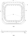
- 1 planar portion
- 2 folded ring portion
- 3 fixing portion
- 4 first soldering portions
- 5 second soldering portions
- 6 middle portions
- 7 electrically conductive metal layer
- 8 wire grooves.
- the embodiment provides a silica gel diaphragm, comprising a planar portion 1 located at a center, a folded ring portion 2 disposed at an edge of the planar portion 1, and a fixing portion 3 connected to the periphery of the folded ring portion 2 for bonding a housing.
- the embodiment etches two symmetrical wire grooves on a surface of the silica gel diaphragm by laser etching technique, so as to ensure the balance of the vibrating diaphragm.
- an electrically conductive metal layer is deposited in each of the wire grooves, and either end of each of the electrically conductive metal layers is provided with a first soldering portion 4 and a second soldering portion 5, respectively; each of the first soldering portions 4 is deposited on a planar portion 1 of the silica gel diaphragm that is closer to the folded ring portion 2, and is used for soldering a winding tap of a voice coil on an inner side of the voice coil; each of the second soldering portions 5 is deposited on a fixing portion 3 of the silica gel diaphragm, and is used for soldering a bonding pad on the housing; and middle portions 6 connecting the first soldering portions 4 and the second soldering portions 5 are deposited in the silica gel diaphragm to form an electrically conductive path.
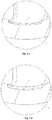
- Figs. 3-a to 3-d jointly illustrate a procedure of depositing the electrically conductive metal layer on the section line A of the silica gel diaphragm provided by the embodiment.
- the state of the silica gel diaphragm where no wire groove is etched on a surface thereof is illustrated by Fig. 3-a
- the state of the silica gel diaphragm where a wire groove is etched on a surface thereof is illustrated by Fig. 3-b
- a metal conductive material is deposited in the wire groove of the silica gel diaphragm by using electrochemical metal deposition method.
- the procedure of depositing the metal conductive material in the wire groove of the silica gel diaphragm is illustrated by Fig.
- An electrically conductive metal layer is obtained after the wire groove of the silica gel diaphragm is completely deposited with the metal conductive material, as illustrated by Fig. 3-d .
- the thickness of the electrically conductive metal layer deposited in Fig. 3-c is less than that of the electrically conductive metal layer deposited in Fig. 3-d .
- the second soldering portions of the two electrically conductive metal layers are preferably deposited at the corners of the fixing portion, as illustrated by Fig. 1 .
- the second soldering portions in the embodiment include, but not limited to, the above configuration.
- the positions of the second soldering portions may be specifically set according to the design requirement on the diaphragm, provided that the soldering with the bonding pads of the housing is possible.
- the upper surfaces of the two electrically conductive metal layers are lower than or flush with the surface of the silica gel diaphragm.
- the first soldering portions of the two electrically conductive metal layers are symmetrically deposited at central positions on the planar portion 1 that are closer to the folded ring portion 2.
- the first soldering portions of the two electrically conductive metal layers may also be disposed at other positions on the planar portion. As illustrated by Fig. 1 , the first soldering portions 4 of the two electrically conductive metal layers are deposited at positions where the polarization of the diaphragm is minimized.
- the first soldering portions 4 of the electrically conductive metal layers in the embodiment of the present disclosure include, but not limited to, the above configuration.
- the positions of the first soldering portions 4 may be specifically set according to the design requirement on the diaphragm, provided that the soldering with the winding tap of the voice coil is possible.
- the embodiment of the present disclosure uses the electrically conductive metal layers deposited on the surface of the silica gel diaphragm to replace the solution of connecting the bonding pads by using the traditional outgoing voice coil lead wires, thereby solving the problem of the collision of the voice coil lead wires, and reducing the noise of the speaker module.
- the embodiments of the present disclosure provide a speaker module, comprising a vibration system received in a housing, wherein the vibration system comprises a diaphragm and a voice coil combined together, and the diaphragm is the silica gel diaphragm provided by the above technical solution.
- the voice coil is fixed on the inner side of the folded ring portion of the silica gel diaphragm.
- the first soldering portions of the two electrically conductive metal layers of the silica gel diaphragm are soldered with the winding taps at the two ends of the voice coil, respectively.
- the second soldering portions of the two electrically conductive metal layers are soldered with the two bonding pads on the housing, respectively.
- first soldering portions of the two electrically conductive metal layers of the silica gel diaphragm are soldered with the winding taps at the two ends of the voice coil, respectively may be understood as soldering the first soldering portion of one electrically conductive metal layer with the winding tap at one end of the voice coil, and soldering the first soldering portion of the other electrically conductive metal layer with the winding tap at the other end of the voice coil.
- That the second soldering portions of the two electrically conductive metal layers of the silica gel diaphragm are soldered with the two bonding pads on the housing, respectively may be understood as soldering the second soldering portion of one electrically conductive metal layer with the positive electrode side of the bonding pad, and soldering the second soldering portion of the other electrically conductive metal layer with the negative electrode side of the bonding pad.
- two electrically conductive metal layers deposited in the silica gel diaphragm are used to replace the voice coil lead wires in traditional solutions, such that the first soldering portions of the two electrically conductive metal layers are soldered with the winding taps on the inner side of the voice coil, and the second soldering portions are soldered with the bonding pads on the housing, thereby solving the problem of the poor audition caused by the collision between the voice coil lead wires and the diaphragm or the housing.
- the embodiments of the present disclosure further provide a method for reprocessing a silica gel diaphragm, the silica gel diaphragm comprising a planar portion located at a center, a folded ring portion disposed at an edge of the planar portion, and a fixing portion connected to the periphery of the folded ring portion for bonding a housing.
- the method for reprocessing a silica gel diaphragm comprises:
- the first soldering portions of the two electrically conductive metal layers are symmetrically deposited at central positions on the planar portion that are closer to the folded ring portion.
- the first soldering portions of the two electrically conductive metal layers may also be disposed at other positions on the planar portion.
- the first soldering portions of the two electrically conductive metal layers are deposited at positions where the polarization of the diaphragm is minimized.
- the first soldering portions of the electrically conductive metal layers in the embodiment include, but not limited to, the above configuration.
- the positions of the first soldering portions may be specifically set according to the design requirement on the diaphragm, provided that the soldering with the winding tap of the voice coil is possible.
- the embodiment etches two symmetrical wire grooves on the surface of the silica gel diaphragm by laser etching technique, and deposits an electrically conductive metal layer in each of the wire grooves by metal deposition technique, such that the soldering portions at the two ends of each of the electrically conductive metal layers can be soldered with the voice coil and the bonding pad, respectively, thereby achieving the connection between the voice coil and the bonding pad.
- the embodiments of the present disclosure provide a silica gel diaphragm, a speaker module and a method for reprocessing a silica gel diaphragm.
- Two symmetrical wire grooves are etched on a surface of the silica gel diaphragm, an electrically conductive metal layer is deposited in each of the wire grooves, and the soldering portions at the two ends of each of the electrically conductive metal layers can be soldered with the voice coil and the bonding pad, respectively, thereby achieving the connection between the voice coil and the bonding pad by using the electrically conductive metal layer.
- the problem of the poor audition caused by the collision of the voice coil lead wires in traditional solutions can be solved, and the acoustic performance of the product can be improved;
- the electrically conductive metal layer deposited in the wire groove does not occupy extra space, and avoids the risk of the breakage of the voice coil lead wires vibrated under a large power, so as to improve the product stability;
- the electrically conductive metal layer is deposited in the etched wire groove, the conductive layer will not easily drop off and becomes more stable, and compared with techniques such as electroplating or magnetron sputtering, the electrically conductive metal layer obtained via metal deposition is more dense and uniform with a higher conductivity, and any crack will not easily occur.
Landscapes
- Engineering & Computer Science (AREA)
- Physics & Mathematics (AREA)
- Acoustics & Sound (AREA)
- Signal Processing (AREA)
- Multimedia (AREA)
- Manufacturing & Machinery (AREA)
- Audible-Bandwidth Dynamoelectric Transducers Other Than Pickups (AREA)
Claims (7)
- Kieselgel-Membran, umfassend einen in einer Mitte angeordneten ebenen Abschnitt (1), einen an einem Rand des ebenen Abschnitts (1) angeordneten gefalteten Ringabschnitt (2) und einen mit dem Umfang des gefalteten Ringabschnitts verbundenen Befestigungsabschnitt (3) zum Bonden eines Gehäuses, dadurch gekennzeichnet, dass zwei symmetrische Leitungsnuten (8) auf einer Oberfläche der Kieselgel-Membran durch Laserätztechnik geätzt sind; und
eine elektrisch leitende Metallschicht (7) in jeder der Leitungsnuten (8) aufgebracht ist, und jedes Ende jeder der elektrisch leitenden Metallschichten mit einem ersten Lötabschnitt (4) und einem zweiten Lötabschnitt (5) versehen ist; jeder der ersten Lötabschnitte (4) auf einem Abschnitt des ebenen Abschnitts der Kieselgel-Membran aufgebracht ist, der näher an dem gefalteten Ringabschnitt (2) liegt, und zum Löten eines Wicklungsabgriffs einer Schwingspule auf einer Innenseite der Schwingspule verwendet wird; jeder der zweiten Lötabschnitte (5) auf dem Befestigungsabschnitt (3) des Kieselgel-Membran aufgebracht ist und zum Löten einer Bondinsel auf das Gehäuse verwendet wird; und Mittelabschnitte (6), die die ersten Lötabschnitte (4) und die zweiten Lötabschnitte (5) verbinden, in dem Kieselgel-Membran aufgebracht sind, um einen elektrisch leitenden Pfad zu bilden. - Kieselgel-Membran nach Anspruch 1, dadurch gekennzeichnet, dass die oberen Oberflächen der beiden elektrisch leitenden Metallschichten (7) niedriger als oder bündig mit der Oberfläche der Kieselgel-Membran sind.
- Kieselgel-Membran nach Anspruch 1, dadurch gekennzeichnet, dass die ersten Lötabschnitte (4) der beiden elektrisch leitenden Metallschichten (7) symmetrisch an zentralen Positionen auf dem ebenen Abschnitt (1), die näher an dem gefalteten Ringabschnitt (2) liegen, aufgebracht sind.
- Lautsprechermodul mit einem in einem Gehäuse aufgenommenen Schwingungssystem, dadurch gekennzeichnet, dass das Schwingungssystem eine Membran und eine Schwingspule umfasst, die miteinander kombiniert sind, wobei die Membran die Kieselgel-Membran nach einem der Ansprüche 1 bis 3 ist; und
die Schwingspule an einer Innenseite des gefalteten Ringabschnitts (2) der Kieselgel-Membran befestigt ist; erste Lötabschnitte (4) von zwei elektrisch leitenden Metallschichten (7) der Kieselgel-Membran jeweils mit Wicklungsabgriffen an zwei Enden der Schwingspule verlötet sind; und zweite Lötabschnitte (5) der zwei elektrisch leitenden Metallschichten (7) jeweils mit zwei Bondinseln auf dem Gehäuse verlötet sind. - Verfahren zum Wiederverarbeiten einer Kieselgel-Membran, wobei die Kieselgel-Membran einen in einer Mitte angeordneten ebenen Abschnitt (1), einen an einem Rand des ebenen Abschnitts (1) angeordneten gefalteten Ringabschnitt (2) und einen mit dem Umfang des gefalteten Ringabschnitts (2) verbundenen Befestigungsabschnitt (3) zum Bonden eines Gehäuses aufweist, dadurch gekennzeichnet, dass das Verfahren umfasst: Ätzen von zwei symmetrischen Leitungsnuten (8) auf einer Oberfläche der Kieselgel-Membran durch Laserätztechnik; und
Aufbringen eines metallischen leitfähigen Materials in den beiden symmetrischen Leitungsnuten (8), um zwei elektrisch leitfähige Metallschichten (7) zu erhalten;
wobei jedes Ende jeder der elektrisch leitfähigen Metallschichten (7) mit einem ersten Lötabschnitt (4) und einem zweiten Lötabschnitt (5) aufgebracht wird; jeder der ersten Lötabschnitte (4) auf einem Abschnitt des planaren Abschnitts (1) der Kieselgel-Membran aufgebracht wird, der näher an dem gefalteten Ringabschnitt (2) liegt, und zum Löten eines Wicklungsabgriffs einer Schwingspule auf einer Innenseite der Schwingspule verwendet wird; jeder der zweiten Lötabschnitte (5) auf einem Befestigungsabschnitt (3) der Kieselgel-Membran aufgebracht wird und zum Löten einer Bondinsel auf das Gehäuse verwendet wird; und Mittelabschnitte (6), die die ersten Lötabschnitte (4) und die zweiten Lötabschnitte (5) verbinden, in der Kieselgel-Membran abgelagert werden, um einen elektrisch leitenden Pfad zu bilden. - Verfahren nach Anspruch 5, dadurch gekennzeichnet, dass das Aufbringen eines metallischen leitfähigen Materials in den zwei symmetrischen Leitungsnuten (8), um zwei elektrisch leitfähige Metallschichten (7) zu erhalten, umfasst:
obere Oberflächen der zwei elektrisch leitfähigen Metallschichten (7) sind niedriger als oder bündig mit der Oberfläche der Kieselgel-Membran. - Verfahren nach Anspruch 5, dadurch gekennzeichnet, dass jeder der ersten Lötabschnitte (4) auf dem ebenen Abschnitt (1) der Kieselgel-Membran aufgebracht wird, der dem gefalteten Ringabschnitt (2) näher liegt, umfassend: die ersten Lötabschnitte (4) der beiden elektrisch leitenden Metallschichten (7) werden symmetrisch an zentralen Positionen auf dem ebenen Abschnitt (1), die dem gefalteten Ringabschnitt (2) näher liegen, aufgebracht.
Applications Claiming Priority (2)
| Application Number | Priority Date | Filing Date | Title |
|---|---|---|---|
| CN201510204166.XA CN104853294B (zh) | 2015-04-23 | 2015-04-23 | 一种硅胶振膜、扬声器模组和再加工硅胶振膜的方法 |
| PCT/CN2015/097964 WO2016169284A1 (zh) | 2015-04-23 | 2015-12-18 | 一种硅胶振膜、扬声器模组和再加工硅胶振膜的方法 |
Publications (3)
| Publication Number | Publication Date |
|---|---|
| EP3288287A1 EP3288287A1 (de) | 2018-02-28 |
| EP3288287A4 EP3288287A4 (de) | 2018-11-21 |
| EP3288287B1 true EP3288287B1 (de) | 2020-09-16 |
Family
ID=53852583
Family Applications (1)
| Application Number | Title | Priority Date | Filing Date |
|---|---|---|---|
| EP15889764.5A Active EP3288287B1 (de) | 2015-04-23 | 2015-12-18 | Kieselsäuregelmembran, lautsprechermodul und verfahren zur aufarbeitung einer kieselsäuregelmembran |
Country Status (4)
| Country | Link |
|---|---|
| US (1) | US10284958B2 (de) |
| EP (1) | EP3288287B1 (de) |
| CN (1) | CN104853294B (de) |
| WO (1) | WO2016169284A1 (de) |
Families Citing this family (10)
| Publication number | Priority date | Publication date | Assignee | Title |
|---|---|---|---|---|
| CN104853294B (zh) | 2015-04-23 | 2019-05-24 | 歌尔股份有限公司 | 一种硅胶振膜、扬声器模组和再加工硅胶振膜的方法 |
| US10560778B2 (en) * | 2015-09-29 | 2020-02-11 | Coleridge Design Associates Llc | System and method for a loudspeaker with a diaphragm |
| WO2017148077A1 (zh) * | 2016-03-04 | 2017-09-08 | 歌尔股份有限公司 | 扬声器振膜及其制造方法、动圈式扬声器 |
| CN106028250A (zh) * | 2016-06-22 | 2016-10-12 | 深圳市摩码克来沃化学科技有限公司 | 硅胶振膜及制备方法、发声部件 |
| US10321235B2 (en) * | 2016-09-23 | 2019-06-11 | Apple Inc. | Transducer having a conductive suspension member |
| JP6887123B2 (ja) * | 2017-03-30 | 2021-06-16 | パナソニックIpマネジメント株式会社 | スピーカおよび移動体装置 |
| CN106937224A (zh) * | 2017-03-31 | 2017-07-07 | 山东共达电声股份有限公司 | 一种不断线平衡振动扬声器 |
| CN208549021U (zh) * | 2018-08-01 | 2019-02-26 | 瑞声光电科技(常州)有限公司 | 发声器件 |
| CN111901731B (zh) * | 2019-05-06 | 2022-01-07 | 奥音科技(北京)有限公司 | 电动声学换能器及其制造方法 |
| CN114286261B (zh) * | 2021-12-30 | 2024-11-22 | 歌尔股份有限公司 | 振膜及其制备方法、发声装置、电子设备 |
Family Cites Families (9)
| Publication number | Priority date | Publication date | Assignee | Title |
|---|---|---|---|---|
| US3569638A (en) * | 1964-02-05 | 1971-03-09 | Electronic Res Ass | Loudspeaker having plastic diaphragm with compliance grooves |
| JP2003199193A (ja) * | 2001-12-27 | 2003-07-11 | Pioneer Electronic Corp | スピーカ装置 |
| US7236608B2 (en) * | 2002-05-02 | 2007-06-26 | Harman International Industries, Incorporated | Conductors for electro-dynamic loudspeakers |
| JP4708134B2 (ja) * | 2005-09-14 | 2011-06-22 | 日東電工株式会社 | 通音膜、通音膜付き電子部品及びその電子部品を実装した回路基板の製造方法 |
| US20070071274A1 (en) * | 2005-09-21 | 2007-03-29 | Andersen Morten K | Insert moulded surround with integrated lead-out wires |
| CN103024638B (zh) * | 2012-11-25 | 2015-09-30 | 歌尔声学股份有限公司 | 电声换能器 |
| CN103281661B (zh) * | 2013-05-09 | 2019-02-05 | 上海集成电路研发中心有限公司 | 一种mems麦克风结构及其制造方法 |
| CN203675306U (zh) * | 2013-07-17 | 2014-06-25 | 嵊州市天乐电声科技有限公司 | 一种手机、平板电脑用扬声器振膜 |
| CN104853294B (zh) * | 2015-04-23 | 2019-05-24 | 歌尔股份有限公司 | 一种硅胶振膜、扬声器模组和再加工硅胶振膜的方法 |
-
2015
- 2015-04-23 CN CN201510204166.XA patent/CN104853294B/zh active Active
- 2015-12-18 EP EP15889764.5A patent/EP3288287B1/de active Active
- 2015-12-18 US US15/552,051 patent/US10284958B2/en active Active
- 2015-12-18 WO PCT/CN2015/097964 patent/WO2016169284A1/zh not_active Ceased
Non-Patent Citations (1)
| Title |
|---|
| None * |
Also Published As
| Publication number | Publication date |
|---|---|
| EP3288287A1 (de) | 2018-02-28 |
| EP3288287A4 (de) | 2018-11-21 |
| CN104853294B (zh) | 2019-05-24 |
| WO2016169284A1 (zh) | 2016-10-27 |
| CN104853294A (zh) | 2015-08-19 |
| US10284958B2 (en) | 2019-05-07 |
| US20180077495A1 (en) | 2018-03-15 |
Similar Documents
| Publication | Publication Date | Title |
|---|---|---|
| EP3288287B1 (de) | Kieselsäuregelmembran, lautsprechermodul und verfahren zur aufarbeitung einer kieselsäuregelmembran | |
| US10375462B2 (en) | Silica gel diaphragm, receiver module, and method for processing silica gel diaphragm | |
| CN208638627U (zh) | 扬声器 | |
| CN103079135B (zh) | 一种单磁体的骨传导耳机装置及其加工方法 | |
| US10979821B2 (en) | Sound generator | |
| US10111008B2 (en) | Miniature speaker | |
| CN101984678A (zh) | 发声器 | |
| CN206963061U (zh) | 定心支片及具有该定心支片的扬声器 | |
| US20200045459A1 (en) | Speaker Assembly | |
| CN109936800B (zh) | 音圈组件的制作方法以及扬声器 | |
| CN110418251B (zh) | 一种发声单体、发声模组及电子终端 | |
| CN209390350U (zh) | 扬声器 | |
| US9820069B2 (en) | Micro speaker with capacitors formed by conductive segmented cover and diaphragm | |
| US20170013380A1 (en) | Micro Speaker | |
| US11838735B2 (en) | Voice coil assembly and loudspeaker | |
| CN103152689B (zh) | 一种提高音圈同心度的喇叭盆架及该喇叭的制造方法 | |
| CN105681985A (zh) | 扬声器振膜及其制造方法、动圈式扬声器 | |
| CN204616070U (zh) | 一种硅胶振膜和扬声器模组 | |
| CN208462041U (zh) | 发声装置及电子设备 | |
| CN108668208A (zh) | 一种扬声器 | |
| CN110418248B (zh) | 金属振膜及扬声器 | |
| US12003939B2 (en) | Voice coil wire for sound generating device, voice coil and sound generating device | |
| CN101867860B (zh) | 一种具有分割电极的电容传声器 | |
| CN203708472U (zh) | 发声器件 | |
| US11516591B2 (en) | Speaker and speaker module |
Legal Events
| Date | Code | Title | Description |
|---|---|---|---|
| STAA | Information on the status of an ep patent application or granted ep patent |
Free format text: STATUS: THE INTERNATIONAL PUBLICATION HAS BEEN MADE |
|
| PUAI | Public reference made under article 153(3) epc to a published international application that has entered the european phase |
Free format text: ORIGINAL CODE: 0009012 |
|
| STAA | Information on the status of an ep patent application or granted ep patent |
Free format text: STATUS: REQUEST FOR EXAMINATION WAS MADE |
|
| 17P | Request for examination filed |
Effective date: 20171013 |
|
| AK | Designated contracting states |
Kind code of ref document: A1 Designated state(s): AL AT BE BG CH CY CZ DE DK EE ES FI FR GB GR HR HU IE IS IT LI LT LU LV MC MK MT NL NO PL PT RO RS SE SI SK SM TR |
|
| AX | Request for extension of the european patent |
Extension state: BA ME |
|
| DAV | Request for validation of the european patent (deleted) | ||
| DAX | Request for extension of the european patent (deleted) | ||
| A4 | Supplementary search report drawn up and despatched |
Effective date: 20181018 |
|
| RIC1 | Information provided on ipc code assigned before grant |
Ipc: H04R 31/00 20060101ALI20181012BHEP Ipc: H04R 7/16 20060101AFI20181012BHEP Ipc: H04R 9/02 20060101ALI20181012BHEP |
|
| STAA | Information on the status of an ep patent application or granted ep patent |
Free format text: STATUS: EXAMINATION IS IN PROGRESS |
|
| 17Q | First examination report despatched |
Effective date: 20190808 |
|
| GRAP | Despatch of communication of intention to grant a patent |
Free format text: ORIGINAL CODE: EPIDOSNIGR1 |
|
| STAA | Information on the status of an ep patent application or granted ep patent |
Free format text: STATUS: GRANT OF PATENT IS INTENDED |
|
| RIC1 | Information provided on ipc code assigned before grant |
Ipc: H04R 7/04 20060101ALI20200326BHEP Ipc: H04R 9/02 20060101ALI20200326BHEP Ipc: H04R 7/16 20060101AFI20200326BHEP Ipc: H04R 1/06 20060101ALI20200326BHEP Ipc: H04R 31/00 20060101ALI20200326BHEP |
|
| INTG | Intention to grant announced |
Effective date: 20200409 |
|
| GRAS | Grant fee paid |
Free format text: ORIGINAL CODE: EPIDOSNIGR3 |
|
| GRAA | (expected) grant |
Free format text: ORIGINAL CODE: 0009210 |
|
| STAA | Information on the status of an ep patent application or granted ep patent |
Free format text: STATUS: THE PATENT HAS BEEN GRANTED |
|
| AK | Designated contracting states |
Kind code of ref document: B1 Designated state(s): AL AT BE BG CH CY CZ DE DK EE ES FI FR GB GR HR HU IE IS IT LI LT LU LV MC MK MT NL NO PL PT RO RS SE SI SK SM TR |
|
| REG | Reference to a national code |
Ref country code: GB Ref legal event code: FG4D |
|
| REG | Reference to a national code |
Ref country code: CH Ref legal event code: EP |
|
| REG | Reference to a national code |
Ref country code: DE Ref legal event code: R096 Ref document number: 602015059365 Country of ref document: DE |
|
| REG | Reference to a national code |
Ref country code: IE Ref legal event code: FG4D |
|
| REG | Reference to a national code |
Ref country code: AT Ref legal event code: REF Ref document number: 1315259 Country of ref document: AT Kind code of ref document: T Effective date: 20201015 |
|
| PG25 | Lapsed in a contracting state [announced via postgrant information from national office to epo] |
Ref country code: SE Free format text: LAPSE BECAUSE OF FAILURE TO SUBMIT A TRANSLATION OF THE DESCRIPTION OR TO PAY THE FEE WITHIN THE PRESCRIBED TIME-LIMIT Effective date: 20200916 Ref country code: FI Free format text: LAPSE BECAUSE OF FAILURE TO SUBMIT A TRANSLATION OF THE DESCRIPTION OR TO PAY THE FEE WITHIN THE PRESCRIBED TIME-LIMIT Effective date: 20200916 Ref country code: GR Free format text: LAPSE BECAUSE OF FAILURE TO SUBMIT A TRANSLATION OF THE DESCRIPTION OR TO PAY THE FEE WITHIN THE PRESCRIBED TIME-LIMIT Effective date: 20201217 Ref country code: NO Free format text: LAPSE BECAUSE OF FAILURE TO SUBMIT A TRANSLATION OF THE DESCRIPTION OR TO PAY THE FEE WITHIN THE PRESCRIBED TIME-LIMIT Effective date: 20201216 Ref country code: BG Free format text: LAPSE BECAUSE OF FAILURE TO SUBMIT A TRANSLATION OF THE DESCRIPTION OR TO PAY THE FEE WITHIN THE PRESCRIBED TIME-LIMIT Effective date: 20201216 Ref country code: HR Free format text: LAPSE BECAUSE OF FAILURE TO SUBMIT A TRANSLATION OF THE DESCRIPTION OR TO PAY THE FEE WITHIN THE PRESCRIBED TIME-LIMIT Effective date: 20200916 |
|
| REG | Reference to a national code |
Ref country code: AT Ref legal event code: MK05 Ref document number: 1315259 Country of ref document: AT Kind code of ref document: T Effective date: 20200916 |
|
| REG | Reference to a national code |
Ref country code: NL Ref legal event code: MP Effective date: 20200916 |
|
| PG25 | Lapsed in a contracting state [announced via postgrant information from national office to epo] |
Ref country code: LV Free format text: LAPSE BECAUSE OF FAILURE TO SUBMIT A TRANSLATION OF THE DESCRIPTION OR TO PAY THE FEE WITHIN THE PRESCRIBED TIME-LIMIT Effective date: 20200916 Ref country code: RS Free format text: LAPSE BECAUSE OF FAILURE TO SUBMIT A TRANSLATION OF THE DESCRIPTION OR TO PAY THE FEE WITHIN THE PRESCRIBED TIME-LIMIT Effective date: 20200916 |
|
| REG | Reference to a national code |
Ref country code: LT Ref legal event code: MG4D |
|
| PG25 | Lapsed in a contracting state [announced via postgrant information from national office to epo] |
Ref country code: SM Free format text: LAPSE BECAUSE OF FAILURE TO SUBMIT A TRANSLATION OF THE DESCRIPTION OR TO PAY THE FEE WITHIN THE PRESCRIBED TIME-LIMIT Effective date: 20200916 Ref country code: PT Free format text: LAPSE BECAUSE OF FAILURE TO SUBMIT A TRANSLATION OF THE DESCRIPTION OR TO PAY THE FEE WITHIN THE PRESCRIBED TIME-LIMIT Effective date: 20210118 Ref country code: RO Free format text: LAPSE BECAUSE OF FAILURE TO SUBMIT A TRANSLATION OF THE DESCRIPTION OR TO PAY THE FEE WITHIN THE PRESCRIBED TIME-LIMIT Effective date: 20200916 Ref country code: EE Free format text: LAPSE BECAUSE OF FAILURE TO SUBMIT A TRANSLATION OF THE DESCRIPTION OR TO PAY THE FEE WITHIN THE PRESCRIBED TIME-LIMIT Effective date: 20200916 Ref country code: LT Free format text: LAPSE BECAUSE OF FAILURE TO SUBMIT A TRANSLATION OF THE DESCRIPTION OR TO PAY THE FEE WITHIN THE PRESCRIBED TIME-LIMIT Effective date: 20200916 Ref country code: CZ Free format text: LAPSE BECAUSE OF FAILURE TO SUBMIT A TRANSLATION OF THE DESCRIPTION OR TO PAY THE FEE WITHIN THE PRESCRIBED TIME-LIMIT Effective date: 20200916 |
|
| PG25 | Lapsed in a contracting state [announced via postgrant information from national office to epo] |
Ref country code: IS Free format text: LAPSE BECAUSE OF FAILURE TO SUBMIT A TRANSLATION OF THE DESCRIPTION OR TO PAY THE FEE WITHIN THE PRESCRIBED TIME-LIMIT Effective date: 20210116 Ref country code: PL Free format text: LAPSE BECAUSE OF FAILURE TO SUBMIT A TRANSLATION OF THE DESCRIPTION OR TO PAY THE FEE WITHIN THE PRESCRIBED TIME-LIMIT Effective date: 20200916 Ref country code: AT Free format text: LAPSE BECAUSE OF FAILURE TO SUBMIT A TRANSLATION OF THE DESCRIPTION OR TO PAY THE FEE WITHIN THE PRESCRIBED TIME-LIMIT Effective date: 20200916 Ref country code: AL Free format text: LAPSE BECAUSE OF FAILURE TO SUBMIT A TRANSLATION OF THE DESCRIPTION OR TO PAY THE FEE WITHIN THE PRESCRIBED TIME-LIMIT Effective date: 20200916 Ref country code: ES Free format text: LAPSE BECAUSE OF FAILURE TO SUBMIT A TRANSLATION OF THE DESCRIPTION OR TO PAY THE FEE WITHIN THE PRESCRIBED TIME-LIMIT Effective date: 20200916 |
|
| REG | Reference to a national code |
Ref country code: DE Ref legal event code: R097 Ref document number: 602015059365 Country of ref document: DE |
|
| PG25 | Lapsed in a contracting state [announced via postgrant information from national office to epo] |
Ref country code: SK Free format text: LAPSE BECAUSE OF FAILURE TO SUBMIT A TRANSLATION OF THE DESCRIPTION OR TO PAY THE FEE WITHIN THE PRESCRIBED TIME-LIMIT Effective date: 20200916 |
|
| PLBE | No opposition filed within time limit |
Free format text: ORIGINAL CODE: 0009261 |
|
| STAA | Information on the status of an ep patent application or granted ep patent |
Free format text: STATUS: NO OPPOSITION FILED WITHIN TIME LIMIT |
|
| REG | Reference to a national code |
Ref country code: CH Ref legal event code: PL |
|
| 26N | No opposition filed |
Effective date: 20210617 |
|
| PG25 | Lapsed in a contracting state [announced via postgrant information from national office to epo] |
Ref country code: MC Free format text: LAPSE BECAUSE OF FAILURE TO SUBMIT A TRANSLATION OF THE DESCRIPTION OR TO PAY THE FEE WITHIN THE PRESCRIBED TIME-LIMIT Effective date: 20200916 Ref country code: DK Free format text: LAPSE BECAUSE OF FAILURE TO SUBMIT A TRANSLATION OF THE DESCRIPTION OR TO PAY THE FEE WITHIN THE PRESCRIBED TIME-LIMIT Effective date: 20200916 Ref country code: SI Free format text: LAPSE BECAUSE OF FAILURE TO SUBMIT A TRANSLATION OF THE DESCRIPTION OR TO PAY THE FEE WITHIN THE PRESCRIBED TIME-LIMIT Effective date: 20200916 |
|
| REG | Reference to a national code |
Ref country code: BE Ref legal event code: MM Effective date: 20201231 |
|
| PG25 | Lapsed in a contracting state [announced via postgrant information from national office to epo] |
Ref country code: LU Free format text: LAPSE BECAUSE OF NON-PAYMENT OF DUE FEES Effective date: 20201218 Ref country code: IE Free format text: LAPSE BECAUSE OF NON-PAYMENT OF DUE FEES Effective date: 20201218 Ref country code: IT Free format text: LAPSE BECAUSE OF FAILURE TO SUBMIT A TRANSLATION OF THE DESCRIPTION OR TO PAY THE FEE WITHIN THE PRESCRIBED TIME-LIMIT Effective date: 20200916 |
|
| PG25 | Lapsed in a contracting state [announced via postgrant information from national office to epo] |
Ref country code: LI Free format text: LAPSE BECAUSE OF NON-PAYMENT OF DUE FEES Effective date: 20201231 Ref country code: CH Free format text: LAPSE BECAUSE OF NON-PAYMENT OF DUE FEES Effective date: 20201231 |
|
| PG25 | Lapsed in a contracting state [announced via postgrant information from national office to epo] |
Ref country code: TR Free format text: LAPSE BECAUSE OF FAILURE TO SUBMIT A TRANSLATION OF THE DESCRIPTION OR TO PAY THE FEE WITHIN THE PRESCRIBED TIME-LIMIT Effective date: 20200916 Ref country code: MT Free format text: LAPSE BECAUSE OF FAILURE TO SUBMIT A TRANSLATION OF THE DESCRIPTION OR TO PAY THE FEE WITHIN THE PRESCRIBED TIME-LIMIT Effective date: 20200916 Ref country code: CY Free format text: LAPSE BECAUSE OF FAILURE TO SUBMIT A TRANSLATION OF THE DESCRIPTION OR TO PAY THE FEE WITHIN THE PRESCRIBED TIME-LIMIT Effective date: 20200916 |
|
| PG25 | Lapsed in a contracting state [announced via postgrant information from national office to epo] |
Ref country code: MK Free format text: LAPSE BECAUSE OF FAILURE TO SUBMIT A TRANSLATION OF THE DESCRIPTION OR TO PAY THE FEE WITHIN THE PRESCRIBED TIME-LIMIT Effective date: 20200916 |
|
| PG25 | Lapsed in a contracting state [announced via postgrant information from national office to epo] |
Ref country code: BE Free format text: LAPSE BECAUSE OF NON-PAYMENT OF DUE FEES Effective date: 20201231 |
|
| PG25 | Lapsed in a contracting state [announced via postgrant information from national office to epo] |
Ref country code: NL Free format text: LAPSE BECAUSE OF NON-PAYMENT OF DUE FEES Effective date: 20200923 |
|
| PGFP | Annual fee paid to national office [announced via postgrant information from national office to epo] |
Ref country code: DE Payment date: 20241211 Year of fee payment: 10 |
|
| PGFP | Annual fee paid to national office [announced via postgrant information from national office to epo] |
Ref country code: GB Payment date: 20241219 Year of fee payment: 10 |
|
| PGFP | Annual fee paid to national office [announced via postgrant information from national office to epo] |
Ref country code: FR Payment date: 20241224 Year of fee payment: 10 |