EP3287318B1 - Transport and load securing device for containers - Google Patents
Transport and load securing device for containers Download PDFInfo
- Publication number
- EP3287318B1 EP3287318B1 EP17186076.0A EP17186076A EP3287318B1 EP 3287318 B1 EP3287318 B1 EP 3287318B1 EP 17186076 A EP17186076 A EP 17186076A EP 3287318 B1 EP3287318 B1 EP 3287318B1
- Authority
- EP
- European Patent Office
- Prior art keywords
- container
- vehicle
- traverses
- transport
- load securing
- Prior art date
- Legal status (The legal status is an assumption and is not a legal conclusion. Google has not performed a legal analysis and makes no representation as to the accuracy of the status listed.)
- Active
Links
- 238000003780 insertion Methods 0.000 claims description 6
- 230000037431 insertion Effects 0.000 claims description 6
- 238000000034 method Methods 0.000 claims description 6
- 239000002184 metal Substances 0.000 claims description 3
- 239000004033 plastic Substances 0.000 claims description 3
- 229920000049 Carbon (fiber) Polymers 0.000 claims 1
- 239000004917 carbon fiber Substances 0.000 claims 1
- VNWKTOKETHGBQD-UHFFFAOYSA-N methane Chemical compound C VNWKTOKETHGBQD-UHFFFAOYSA-N 0.000 claims 1
- 239000004918 carbon fiber reinforced polymer Substances 0.000 description 1
- 230000001419 dependent effect Effects 0.000 description 1
- 238000006073 displacement reaction Methods 0.000 description 1
- 239000002990 reinforced plastic Substances 0.000 description 1
Images


Classifications
-
- B—PERFORMING OPERATIONS; TRANSPORTING
- B60—VEHICLES IN GENERAL
- B60P—VEHICLES ADAPTED FOR LOAD TRANSPORTATION OR TO TRANSPORT, TO CARRY, OR TO COMPRISE SPECIAL LOADS OR OBJECTS
- B60P7/00—Securing or covering of load on vehicles
- B60P7/06—Securing of load
- B60P7/08—Securing to the vehicle floor or sides
- B60P7/0892—Securing to the vehicle floor or sides by preventing lateral movement of the load, e.g. using stop blocks
Definitions
- the invention relates to a transport and load securing for containers and an associated method.
- a generic fuse is in US 3754516 A disclosed.
- anti-slip mats are arranged under the containers and on the loading area in order to prevent containers from slipping on the loading area during transport.
- straps can alternatively or additionally be used to secure the containers on the loading surface.
- the containers are standardized and the containers have a grid dimension, ie there is a kind of "kit” on containers.
- the containers generally have the same function and the same appearance, but have different sizes, for example in the base area and / or the container height.
- the containers can thereby be stacked and / or stored and / or transported in a simplified manner.
- a grid dimension for a set of containers is often chosen such that the base area of a container is a whole multiple of the base area of a "base container", ie the smallest container.
- base container ie the smallest container.
- smaller containers can be arranged on larger containers so that the base area of the larger container is fully utilized. For example, two 1 ⁇ 2 containers on one 1/1 containers are placed, whereby the base of the 1/1 container is fully used.
- a disadvantage of the known transport and load securing devices is that the success of securing the containers is heavily dependent on the user.
- the vehicle cross members and / or the container cross members preferably each run parallel to one another.
- the vehicle traverses are advantageously connected to the vehicle by means of a screw connection or in particular a detachable plug connection.
- the vehicle crossbars are preferably arranged in the direction of travel of the vehicle, perpendicular to it or at any angle in between.
- the vehicle crossbars advantageously each have one end of a plug connection in the longitudinal direction, in particular a dovetail connection, so that the vehicle crossbars can be connected to one another in the longitudinal direction thereof.
- the vehicle and / or container crossbars preferably consist of metal or plastic, in particular CFRP reinforced.
- the vehicle crossbars advantageously have an insertion section for inserting a container crossbar between adjacent vehicle crossbars and one Undercut to move the container crossbar between the vehicle crossbar and the loading area of the vehicle.
- the opposite container traverses are advantageously adjacent container traverses.
- the container crossbars are preferably arranged perpendicular to the vehicle crossbars.
- the container traverses are advantageously mirror-symmetrical to the longitudinal and / or transverse axis.
- a grid dimension of the engagement shells is advantageously matched to a grid dimension of the container feet of the containers, so that all container feet on one side of the container are held by a container traverse.
- Container traverses are preferably attached to the vehicle and / or the vehicle traverses.
- the engagement shells are advantageously formed without an undercut in order to prevent the container from slipping parallel to the loading area.
- the engaging shells preferably have a vertical holding means, in particular a projection, in order to prevent the container from being displaced perpendicularly to the loading area of the vehicle.
- the dimensions of the projection in the engagement shell and a corresponding undercut in the container base are preferably such that the container base is supported on the one hand by the associated container crossmember and on the other by the loading area of the vehicle (double support).
- the vehicle can be a truck, a van, a car or a flatbed truck.
- the container is advantageously a storage box with or without a lid.
- the cross section of the container feet is advantageously round, for example circular or elliptical, or polygonal, for example rectangular or square.
- Fig. 1 shows different views of a pair of first vehicle cross members 7
- Figure 2 shows different views of a pair of second vehicle cross members 7.
- the two pairs of vehicle cross members 7 can each be connected to one another via a dovetail connection 13.
- the vehicle cross members 7 of the Fig. 1 a groove 13N and the vehicle cross members 7 of the Fig. 2 a spring 13F of a dovetail joint 13.
- the two pairs of vehicle traverses 7 the Figures 1 and 2 Connected to one another via the dovetail connection, they are fastened to the loading area 5L of a vehicle 5, the length of the assembled vehicle traverses 7 corresponding to a desired length and, for example, corresponding to the length of the loading area 5L in the direction of travel 5F of the vehicle 5.
- the first and second pairs of vehicle cross members 7 are as from Fig. 1a ) and 2a ) can be seen, each mirror-symmetrical.
- the vehicle traverses are formed as hollow profiles made of metal, alternatively, for example, made of a plastic, in particular a reinforced plastic.
- Through bores 7B are provided in the vehicle crossbars 7 in order to fasten the vehicle crossbars 7 to the loading area 5L of the vehicle 5 by means of screws.
- insertion sections 7E are provided to arrange a container traverse 9 between them, as further described below.
- vehicle traverses 7 have undercuts 7H assigned to the insertion sections 7E, along which the container traverses 9 are displaceable, as also described below.
- FIG. 3 Different views of the container traverse 9 for arrangement between two vehicle traverses 7 are shown.
- the container traverse 9 is also a metallic hollow profile.
- the container crossmember 9 each has an undercut 9H, as a result of which an intermediate section 9Z projecting in the longitudinal direction is formed.
- the intermediate section is provided for arrangement between the loading area 5L and a vehicle crossbar 7 in the region of the undercut 7H, as described further below.
- vertical height of the intermediate section 9Z perpendicular to the longitudinal direction of the container crossbar 9 therefore corresponds to the height of the undercut 7H of the vehicle crossbar.
- Opposing engagement shells 9E are formed on opposite longitudinal sides 9L of the container traverse, which are formed in a semicircular shape.
- the engaging shells 9E are substantially in the shape of a half cylinder, but a semicircular projection 9V is formed in the center thereof. With these engagement shells it is possible to enclose a container base 3F of a container 3 in a semicircular manner, as described further below.
- the container traverse 9 is constructed symmetrically along the longitudinal axis thereof. Furthermore, the container crossbar 9 is symmetrical perpendicular to an axis which divides the container crossbar 9 centrally in the longitudinal direction.
- Fig. 4 shows different views of the container base 3F of a container 3.
- the container base 3F has an essentially cylindrically symmetrical shape.
- upper end is formed a recess to connect the container base 3F with its container 3.
- an annular undercut 3H is formed in the container base 3.
- the projection 9V of the engagement shell 9E engages in a semicircular manner as described below.
- the axial of the undercut 3H in Fig. 4c corresponds to the thickness of the projection 9V in the same direction.
- FIGS. 5 ) and 6 ) show different views of the transport and load securing 1, with container feet 3 of containers 3, not shown, also being shown for easier understanding.
- the pair of first vehicle traverses 7 of the Fig. 1 is connected to the pair of second vehicle cross members 7 via the dovetail connection 13, ie the groove 13N has received the spring 13F, as a result of which a mechanical plug connection is formed between the vehicle cross members 7.
- the engagement shells 9E enclose the container feet 3F in a semicircular shape, the projection 9V also engaging in the undercut 3H in a semicircular shape. Because the thickness of the projection 9V corresponds to the height of the undercut 3H, each container foot 3F presses on the one hand with its undercut 3H on the projection 9V and on the other hand with its free end on the loading area 5L of the vehicle 5.
- the container base 3F is no longer displaceable in the axial direction thereof.
- the container foot 3F is held securely in the axial direction and is not displaceable. In this way, during a transport of containers 3 with a vehicle 5, the lifting of containers 3 from the loading area 5L of the vehicle 5 can be prevented.
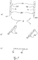
- FIG Fig. 7 In order to secure the transport and load of containers 3 on a vehicle 5, reference is made to FIG Fig. 7 ) proceeded as follows: This in Fig. 7 Flatbed vehicle 5 shown has a loading area 5L. The arrow 5F indicates the direction of travel of the vehicle 5 when the vehicle 5 is traveling forward.
- the pair of first vehicle cross members 7 becomes the Fig. 1 with the pair of second cross members 7 of the Fig. 2 mechanically connected by means of the dovetail connection 13.
- the interconnected vehicle traverses 7 are arranged parallel to one another on the loading surface 5L of the vehicle, the relative distance from one another depending on the length of the container traverses 9.
- the vehicle traverses 7 are firmly connected to the loading area 5L of the vehicle 5.
- screws are screwed through the through holes 7B of the vehicle crossbar 7 into the loading area 5L in order to form a screw connection 11 between the vehicle crossbars 7 and the vehicle 5.
- Alternative mechanical connections are possible.
- a plug connection could be formed between the vehicle cross members 7 and the loading area 5L.
- a first container crossbar 9 is arranged between the vehicle crossbars 7, the intermediate sections 9Z of the container crossbar 9 being arranged in the insertion sections 7E of the vehicle crossbar 7.
- the container traverse 9 is lowered in an orientation onto the loading surface 5L that corresponds to the orientation of the Fig. 3c ) corresponds, but the container crossbar 9 is rotated by 180 ° along the longitudinal axis.
- the container crossbar 9 is displaced in the direction of travel 5F so that the intermediate section 9Z is arranged completely in the region of the undercut 7H of the vehicle crossbar and is thus arranged between the loading surface 5L and the vehicle crossbar 7. Because the thickness of the intermediate section 9Z corresponds to the height of the undercut 7H at this point, a displacement of the container traverse 9 perpendicular to the loading area 5L is not possible.
- the container crossbar 9 is fastened in this position, in the present case screws are screwed through the container crossbar 9 and into the loading area 5L of the vehicle.
- the container traverse 9 can be screwed to the vehicle traverse 7.
- latching or plug connections can be formed in a known manner between the container crossbar 9 and the vehicle crossbar 7.
- a container 3 with container feet 3F is shifted in the four corners of its base surface in the direction of travel 5F on the loading surface 5L until the container feet 5F engage in the engagement shells 9E of the container traverse 9.
- the engagement shells 9E each surround the container base 3F in a semicircular shape, the projection 9V engaging in the undercut 3H.
- a further container crossbar 9 is now arranged between the vehicle crossbars 7, lowered onto the loading surface 5L and shifted in the direction of travel 5F, as described above for the first container crossbar 9, until the second container crossbar 9 with its engaging shells 9E on the container feet 3F strikes.
- the engagement shells 9E again encircle the container feet 3F in a semicircular shape, the projection 9V engaging in the undercut 3H, as described above.
- the second container traverse 9 is fastened in this position.
- the attachment takes place as described above for the attachment of the first container traverse 9, i.e. in the present case by means of a screw connection.
- the container 3 is now held on the vehicle 5 by the transport and load securing device 1: due to the cylindrical shape of the engagement shells 9E and the container feet 3F, the container 3 is displaced in the plane of the loading area 5L prevents.
- the projection 9V in the container traverse and the undercut 3H in the container base 3 also prevent the container 3 from being displaced perpendicularly to the loading surface 5L.
- the undercut 3H and the projection 9V were selected as the vertical holding means.
- Alternative embodiments of the vertical holding means are possible.
- the undercut is formed in the engagement shell and the projection on the container base.
- two or more undercuts can work together with a corresponding number of projections, the undercuts being able to be formed both in the container feet and in the engaging shells (and accordingly the projections in the engaging shells or the container feet).
- cone-shaped undercuts or projections are conceivable or combinations of ring-shaped and cone-shaped undercuts and projections.
- the engagement shells encircle the container feet in a semicircle, ie in an angular range of 180 °.
- the angular range should preferably be greater than 90 ° in order to achieve a good or sufficient hold.
Landscapes
- Engineering & Computer Science (AREA)
- Transportation (AREA)
- Mechanical Engineering (AREA)
- Body Structure For Vehicles (AREA)
- Fittings On The Vehicle Exterior For Carrying Loads, And Devices For Holding Or Mounting Articles (AREA)
- Passenger Equipment (AREA)
Description
Die Erfindung betrifft eine Transport- und Ladungssicherung für Behälter und ein zugehöriges Verfahren. Eine gattungsgemäße Sicherung ist in
Um Behälter auf einer Ladefläche eines Fahrzeugs während der Fahrt zu sichern, sind verschiedene Transport- und Ladungssicherungen bekannt.In order to secure containers on a loading area of a vehicle while driving, various transport and load securing devices are known.
In einer ersten Variante werden Anti-Rutschmatten unter den Behältern und auf der Ladefläche angeordnet, um ein Verrutschen von Behältern auf der Ladefläche während des Transports zu vermeiden. Bei höheren Geschwindigkeiten des Fahrzeugs oder bei größeren Massen der Behälter können alternativ oder zusätzlich Spanngurte verwendet werden, um die Behälter auf der Ladefläche zu sichern.In a first variant, anti-slip mats are arranged under the containers and on the loading area in order to prevent containers from slipping on the loading area during transport. At higher vehicle speeds or with larger container weights, straps can alternatively or additionally be used to secure the containers on the loading surface.
In vielen gewerblichen Anwendungen, bspw. bei Handwerkern, sind die Behälter normiert und die Behälter haben ein Rastermaß, d.h. es gibt eine Art "Bausatz" an Behältern. Die Behälter weisen in der Regel die gleiche Funktion und das gleiche Aussehen aus, weisen jedoch unterschiedliche Größen auf, bspw. in der Grundfläche und/oder der Behälterhöhe. Die Behälter können dadurch vereinfacht gestapelt und/oder gelagert und/oder transportiert werden. Häufig wird ein Rastermaß für einen Satz von Behältern so gewählt, dass die Grundfläche eines Behälters ein ganzes Vielfaches der Grundfläche eines "Grundbehälters", d.h. eines kleinsten Behälters ist. Auf diese Weise können kleinere Behälter auf größere Behälter so angeordnet werden, dass die Grundfläche des größeren Behälters vollständig ausgenutzt ist, Beispielsweise können zwei ½-Behälter auf einem 1/1-Behälter gestellt werden, wodurch die Grundfläche des 1/1-Behälters vollständig ausgenutzt ist.In many commercial applications, for example for craftsmen, the containers are standardized and the containers have a grid dimension, ie there is a kind of "kit" on containers. The containers generally have the same function and the same appearance, but have different sizes, for example in the base area and / or the container height. The containers can thereby be stacked and / or stored and / or transported in a simplified manner. A grid dimension for a set of containers is often chosen such that the base area of a container is a whole multiple of the base area of a "base container", ie the smallest container. In this way, smaller containers can be arranged on larger containers so that the base area of the larger container is fully utilized. For example, two ½ containers on one 1/1 containers are placed, whereby the base of the 1/1 container is fully used.
Ein Nachteil der bekannten Transport- und Ladungssicherungen ist, dass der Erfolg der Sicherung der Behälter stark von dem Anwender abhängig ist.A disadvantage of the known transport and load securing devices is that the success of securing the containers is heavily dependent on the user.
Bei Fahrzeugen, die genormte Behälter transportieren, ist eine einfache und verlässlich funktionierende Ladungs- und Transportsicherung der Behälter gewünscht.For vehicles that transport standardized containers, a simple and reliably functioning load and transport securing of the containers is desired.
Diese Aufgabe wird erfindungsgemäß zum einen durch den unabhängigen Vorrichtungsanspruch und zum anderen durch den unabhängigen Verfahrensanspruch gelöst.This object is achieved on the one hand by the independent device claim and on the other hand by the independent method claim.
Bevorzugt verlaufen die Fahrzeugtraversen und/oder die Behältertraversen jeweils parallel zueinander.The vehicle cross members and / or the container cross members preferably each run parallel to one another.
Mit Vorteil sind die Fahrzeugtraversen mittels einer Schraub- oder einer insbes. lösbaren Steckverbindung mit dem Fahrzeug verbunden.The vehicle traverses are advantageously connected to the vehicle by means of a screw connection or in particular a detachable plug connection.
Bevorzugt sind die Fahrzeugtraversen in Fahrtrichtung des Fahrzeugs, senkrecht dazu oder in einem beliebigen Winkel dazwischen angeordnet.The vehicle crossbars are preferably arranged in the direction of travel of the vehicle, perpendicular to it or at any angle in between.
Mit Vorteil weisen die Fahrzeugtraversen in Längsrichtung jeweils ein Ende einer Steckverbindung auf, insbes. einer Schwalbenschwanzverbindung, so dass die Fahrzeugtraversen in Längsrichtung derselben miteinander steckbar verbindbar sind.The vehicle crossbars advantageously each have one end of a plug connection in the longitudinal direction, in particular a dovetail connection, so that the vehicle crossbars can be connected to one another in the longitudinal direction thereof.
Bevorzugt bestehen die Fahrzeug- und/oder Behältertraversen aus Metall oder Kunststoff, insbes. CFKverstärkt.The vehicle and / or container crossbars preferably consist of metal or plastic, in particular CFRP reinforced.
Mit Vorteil weisen die Fahrzeugtraversen einen Einführabschnitt auf, um eine Behältertraverse zwischen benachbarten Fahrzeugtraversen einzuführen, und einen Hinterschnitt, um die Behältertraverse zwischen Fahrzeugtraverse und Ladefläche des Fahrzeugs zu verschieben.The vehicle crossbars advantageously have an insertion section for inserting a container crossbar between adjacent vehicle crossbars and one Undercut to move the container crossbar between the vehicle crossbar and the loading area of the vehicle.
Vorteilhaft sind die gegenüberliegenden Behältertraversen benachbarte Behältertraversen.The opposite container traverses are advantageously adjacent container traverses.
Bevorzugt sind die Behältertraversen senkrecht zu den Fahrzeugtraversen angeordnet.The container crossbars are preferably arranged perpendicular to the vehicle crossbars.
Vorteilhaft sind die Behältertraversen spiegelsymmetrisch zur Längs- und/oder Querachse ausgebildet.The container traverses are advantageously mirror-symmetrical to the longitudinal and / or transverse axis.
Ein Rastermaß der Eingriffschalen ist vorteilhaft auf ein Rastermaß der Behälterfüße der Behälter abgestimmt, damit alle Behälterfüße einer Seite des Behälters von einer Behältertraverse gehalten sind.A grid dimension of the engagement shells is advantageously matched to a grid dimension of the container feet of the containers, so that all container feet on one side of the container are held by a container traverse.
Bevorzugt sind Behältertraversen an dem Fahrzeug und/oder den Fahrzeugtraversen befestigt.Container traverses are preferably attached to the vehicle and / or the vehicle traverses.
Mit Vorteil sind die Eingriffschalen ohne Hinterschnitt gebildet, um ein Verrutschen des Behälters parallel zu der Ladefläche zu verhindern.The engagement shells are advantageously formed without an undercut in order to prevent the container from slipping parallel to the loading area.
Bevorzugt weisen die Eingriffschalen ein Vertikalhaltemittel auf, insbesondere einen Vorsprung, um ein Verschieben des Behälters senkrecht zur Ladefläche des Fahrzeugs zu verhindern.The engaging shells preferably have a vertical holding means, in particular a projection, in order to prevent the container from being displaced perpendicularly to the loading area of the vehicle.
Bevorzugt sind der Vorsprung in der Eingriffschale und ein korrespondierender Hinterschnitt im Behälterfuß von den Abmessungen her so aufeinander abgestimmt sind, dass der Behälterfuß zum einen von der zugehörigen Behältertraverse und zum anderen von der Ladefläche des Fahrzeugs abgestützt ist (doppelte Abstützung).The dimensions of the projection in the engagement shell and a corresponding undercut in the container base are preferably such that the container base is supported on the one hand by the associated container crossmember and on the other by the loading area of the vehicle (double support).
Das Fahrzeug kann ein LKW, ein Transporter, ein PKW oder ein Pritschenwagen sein.The vehicle can be a truck, a van, a car or a flatbed truck.
Mit Vorteil ist der Behälter eine Lagerbox mit oder ohne Deckel.The container is advantageously a storage box with or without a lid.
Vorteilhaft ist der Querschnitt der Behälterfüße rund, bspw. kreisförmig oder elliptisch, oder polygonal, bspw. rechteckig oder quadratisch.The cross section of the container feet is advantageously round, for example circular or elliptical, or polygonal, for example rectangular or square.
Bevorzugt durch Wiederholen der Schritte b) bis d) des unabhängigen Verfahrensanspruchs mit jeweils mindestens einer weiteren Behältertraverse mit zugehörigen Behälter kann mindestens ein weiterer Behälter an der Ladefläche gehalten werden.Weitere Merkmale, Einzelheiten und Vorzüge der Erfindung ergeben sich aus den Ansprüchen und der nachfolgenden Beschreibung bevorzugter Ausführungsformen sowie anhand der Zeichnung. Es zeigen:
- Fig. 1
- a) eine Draufsicht, b) eine perspektivische und c) eine Seitenansicht einer ersten Fahrzeugtraverse,
- Fig. 2
- a) eine Draufsicht, b) eine perspektivische und c) eine Seitenansicht einer zweiten Fahrzeugtraverse zur Verbindung mit der ersten Fahrzeugtraverse,
- Fig. 3
- a) eine Draufsicht, b) eine Seitenansicht und c) eine perspektivische Ansicht einer Behältertraverse,
- Fig. 4
- a) eine perspektivische, b) eine Draufsicht und c) eine Seitenansicht eines Behälterfusses eines Behälters für die erfindungsgemäße Transport- und Ladungssicherung,
- Fig. 5
- a) eine Draufsicht, b) eine ersten Seitenansicht, c) eine zweite Seitenansicht und d) eine perspektivische Ansicht einer erfindungsgemäßen Transport- und Ladungssicherung für eine Ladefläche eines Fahrzeugs, wobei Behälterfüße von nicht dargestellten Behältern in derselben dargestellt sind,
- Fig. 6
- eine vergrößerte perspektivische Ansicht der Anordnung der
Fig. 5 , und - Fig. 7
- eine perspektivische Ansicht eines Pritschenwagens mit einer Ladefläche, auf der eine erfindungsgemäße Transport- und Ladungssicherung angeordnet ist, in der ein Behälter gesichert ist, von zwei nicht dargestellten Behältern sind nur die Behälterfüße dargestellt.
- Fig. 1
- a) a top view, b) a perspective and c) a side view of a first vehicle cross member,
- Fig. 2
- a) a top view, b) a perspective and c) a side view of a second vehicle crossbar for connection to the first vehicle crossbar,
- Fig. 3
- a) a top view, b) a side view and c) a perspective view of a container traverse,
- Fig. 4
- a) a perspective, b) a top view and c) a side view of a container foot of a container for the transport and load securing according to the invention,
- Fig. 5
- a) a top view, b) a first side view, c) a second side view and d) a perspective view of a transport and load securing device according to the invention for a loading area of a vehicle, container feet of containers, not shown, being shown therein,
- Fig. 6
- an enlarged perspective view of the arrangement of the
Fig. 5 , and - Fig. 7
- a perspective view of a platform truck with a loading surface, on which a transport and load securing device according to the invention is arranged, in which a container is secured, of two containers, not shown, only the container feet are shown.
Die ersten und zweiten Paare an Fahrzeugtraversen 7 sind, wie aus
In den Fahrzeugtraversen 7 sind durchgehende Bohrungen 7B vorgesehen, um die Fahrzeugtraversen 7 mittels Schrauben an der Ladefläche 5L des Fahrzeugs 5 zu befestigen.Through
An gegenüberliegenden Längsseiten 7L der Paare der Fahrzeugtraversen der
Ferner weisen die Fahrzeugtraversen 7 den Einführabschnitten 7E zugeordnete Hinterschnitte 7H auf, entlang derer die Behältertraversen 9 verschieblich sind, wie ebenfalls weiter unten beschrieben.Furthermore, the vehicle traverses 7 have
In
An gegenüberliegenden Enden weist die Behältertraverse 9 jeweils einen Hinterschnitt 9H auf, wodurch ein in Längsrichtung vorstehender Zwischenabschnitt 9Z gebildet ist. Der Zwischenabschnitt ist vorgesehen zur Anordnung zwischen der Ladefläche 5L und einer Fahrzeugtraverse 7 im Bereich des Hinterschnitts 7H, wie weiter unten beschrieben. Die in
An gegenüberliegenden Längsseiten 9L der Behältertraverse sind gegenüberliegende Eingriffschalen 9E gebildet, die halbkreisförmig gebildet sind. Die Eingriffschalen 9E weisen im Wesentlichen die Form eines Halbzylinders auf, wobei jedoch in der Mitte desselben ein halbkreisförmiger Vorsprung 9V gebildet ist. Mit diesen Eingriffschalen ist es möglich, einen Behälterfuß 3F eines Behälters 3 halbkreisförmig zu umschließen, wie weiter unten beschrieben.Opposing
Die Behältertraverse 9 ist entlang der Längsachse derselben symmetrisch aufgebaut. Ferner ist die Behältertraverse 9 senkrecht zu einer Achse symmetrisch, die die Behältertraverse 9 in Längsrichtung mittig teilt.The container traverse 9 is constructed symmetrically along the longitudinal axis thereof. Furthermore, the container crossbar 9 is symmetrical perpendicular to an axis which divides the container crossbar 9 centrally in the longitudinal direction.
Die
Das Paar von ersten Fahrzeugtraversen 7 der
Wie insbesondere in
Dadurch, dass der Vorsprung 9V in den Hinterschnitt 3H greift, ist der Behälterfuß 3F in axialer Richtung desselben nicht mehr verschieblich. Mit anderen Worten ist der Behälterfuß 3F in axialer Richtung sicher gehalten und nicht verschieblich. Während eines Transports von Behältern 3 mit einem Fahrzeug 5 kann auf diese Weise das Abheben von Behältern 3 von der Ladefläche 5L des Fahrzeugs 5 verhindert werden.Because the projection 9V engages in the undercut 3H, the container base 3F is no longer displaceable in the axial direction thereof. In other words, the container foot 3F is held securely in the axial direction and is not displaceable. In this way, during a transport of
Um die Transport- und Ladungssicherung von Behältern 3 an einem Fahrzeug 5 vorzunehmen, wird unter Bezug auf
Das in
This in
In einem ersten Schritt wird das Paar von ersten Fahrzeugtraversen 7 der
In einem zweiten Schritt werden die miteinander verbundenen Fahrzeugtraversen 7 auf der Ladefläche 5L des Fahrzeugs parallel zueinander angeordnet, wobei der relative Abstand zueinander von der Länge der Behältertraversen 9 abhängt.In a second step, the interconnected vehicle traverses 7 are arranged parallel to one another on the loading surface 5L of the vehicle, the relative distance from one another depending on the length of the container traverses 9.
In einem dritten Schritt werden die Fahrzeugtraversen 7 fest mit der Ladefläche 5L des Fahrzeugs 5 verbunden. Vorliegend werden Schrauben durch die Durchgangsbohrungen 7B der Fahrzeugtraverse 7 in die Ladefläche 5L geschraubt, um eine Schraubverbindung 11 zwischen den Fahrzeugtraversen 7 und dem Fahrzeug 5 zu bilden. Alternative mechanische Verbindungen sind möglich. Beispielsweise könnte eine Steckverbindung zwischen den Fahrzeugtraversen 7 und der Ladefläche 5L gebildet sein.In a third step, the vehicle traverses 7 are firmly connected to the loading area 5L of the vehicle 5. In the present case, screws are screwed through the through
In einem vierten Schritt wird eine erste Behältertraverse 9 zwischen den Fahrzeugtraversen 7 angeordnet, wobei die Zwischenabschnitte 9Z der Behältertraverse 9 in den Einführabschnitten 7E der Fahrzeugtraverse 7 angeordnet sind. Die Behältertraverse 9 wird in einer Orientierung auf die Ladefläche 5L abgesenkt, die der Orientierung der
In einem fünften Schritt wird die Behältertraverse 9 in Fahrtrichtung 5F so weit verschoben, dass der Zwischenabschnitt 9Z vollständig im Bereich des Hinterschnitts 7H der Fahrzeugtraverse angeordnet ist und somit zwischen der Ladefläche 5L und der Fahrzeugtraverse 7 angeordnet ist. Da die Dicke des Zwischenabschnitts 9Z der Höhe des Hinterschnitts 7H an dieser Stelle entspricht, ist eine Verschiebung der Behältertraverse 9 senkrecht zur Ladefläche 5L nicht möglich.In a fifth step, the container crossbar 9 is displaced in the direction of travel 5F so that the intermediate section 9Z is arranged completely in the region of the undercut 7H of the vehicle crossbar and is thus arranged between the loading surface 5L and the
In einem sechsten Schritt wird die Behältertraverse 9 in dieser Position befestigt, vorliegend werden Schrauben durch die Behältertraverse 9 und in die Ladefläche 5L des Fahrzeugs geschraubt. Alternativ oder zusätzlich kann die Behältertraverse 9 mit der Fahrzeugtraverse 7 verschraubt werden. Ferner können Rast- oder Steckverbindungen auf bekannte Weise zwischen der Behältertraverse 9 und der Fahrzeugtraverse 7 gebildet sein.In a sixth step, the container crossbar 9 is fastened in this position, in the present case screws are screwed through the container crossbar 9 and into the loading area 5L of the vehicle. Alternatively or additionally, the container traverse 9 can be screwed to the
In einem siebten Schritt wird ein Behälter 3 mit Behälterfüßen 3F in den vier Ecken seiner Grundfläche so weit in Fahrtrichtung 5F auf der Ladefläche 5L verschoben, bis die Behälterfüße 5F in die Eingriffschalen 9E der Behältertraverse 9 greifen. Wie oben beschrieben, umschließen die Eingriffschalen 9E jeweils halbkreisförmig den Behälterfuß 3F, wobei der Vorsprung 9V in den Hinterschnitt 3H greift.In a seventh step, a
In einem achten Schritt wird nun eine weitere Behältertraverse 9 zwischen den Fahrzeugtraversen 7 angeordnet, auf die Ladefläche 5L abgesenkt und in Fahrtrichtung 5F verschoben, wie dies für die erste Behältertraverse 9 oben beschrieben ist, bis die zweite Behältertraverse 9 mit ihren Eingriffschalen 9E an den Behälterfüßen 3F anschlägt. In dieser Position umgreifen die Eingriffschalen 9E wieder die Behälterfüße 3F halbkreisförmig, wobei der Vorsprung 9V in den Hinterschnitt 3H greift, wie oben beschrieben.In an eighth step, a further container crossbar 9 is now arranged between the
In einem neunten Schritt wird die zweite Behältertraverse 9 in dieser Position befestigt. Die Befestigung erfolgt dabei wie zuvor für die Befestigung der ersten Behältertraverse 9 beschrieben, d.h. vorliegend mittels einer Verschraubung.In a ninth step, the second container traverse 9 is fastened in this position. The attachment takes place as described above for the attachment of the first container traverse 9, i.e. in the present case by means of a screw connection.
Der Behälter 3 ist nun durch die Transport- und Ladungssicherung 1 an dem Fahrzeug 5 gehalten: Durch die Zylinderform der Eingriffschalen 9E und der Behälterfüße 3F ist eine Verschiebung des Behälters 3 in der Ebene der Ladefläche 5L verhindert. Durch den Vorsprung 9V in der Behältertraverse und den Hinterschnitt 3H in dem Behälterfuß 3 ist auch eine Verschiebung des Behälters 3 senkrecht zur Ladefläche 5L verhindert.The
Um einen weiteren Behälter 3 auf der Ladefläche 5L zu sichern, werden die oben beschriebenen Schritte sieben bis neun zur Befestigung des ersten Behälters wiederholt.In order to secure another
In der vorliegenden Ausführungsform wurde als Vertikalhaltemittel der Hinterschnitt 3H und der Vorsprung 9V gewählt. Alternative Ausführungsformen des Vertikalhaltemittel sind möglich. In einer ersten Variante ist der Hinterschnitt in der Eingriffschale und der Vorsprung an dem Behälterfuß gebildet. In einer weiteren Variante können zwei oder mehr Hinterschnitte mit einer entsprechenden Anzahl von Vorsprüngen zusammen arbeiten, wobei die Hinterschnitte sowohl in den Behälterfüßen als auch in den Eingriffschalen gebildet sein können (und entsprechend die Vorsprünge in den Eingriffschalen bzw. den Behälterfüßen). Alternativ zu ringförmigen Vorsprüngen oder Hinterschnitten sind kegelförmige Hinterschnitte bzw. Vorsprünge denkbar oder Kombinationen von ring- und kegelfömigen Hinterschnitten und Vorsprüngen.In the present embodiment, the undercut 3H and the projection 9V were selected as the vertical holding means. Alternative embodiments of the vertical holding means are possible. In a first variant, the undercut is formed in the engagement shell and the projection on the container base. In a further variant, two or more undercuts can work together with a corresponding number of projections, the undercuts being able to be formed both in the container feet and in the engaging shells (and accordingly the projections in the engaging shells or the container feet). As an alternative to ring-shaped projections or undercuts, cone-shaped undercuts or projections are conceivable or combinations of ring-shaped and cone-shaped undercuts and projections.
Vorliegend umgreifen die Eingriffschalen die Behälterfüße halbkreisförmig, d.h. in einem Winkelbereich von 180°. Andere Winkelbereiche sind möglich, wobei der Winkelbereich bevorzugt größer als 90° sein sollte, um einen guten bzw. ausreichenden Halt zu erreichen.In the present case, the engagement shells encircle the container feet in a semicircle, ie in an angular range of 180 °. Other angular ranges are possible, the angular range should preferably be greater than 90 ° in order to achieve a good or sufficient hold.
- 11
- Transport- und LadungssicherungTransport and load securing
- 33
- Behältercontainer
- 3F3F
- Behälterfußbowl foot
- 3H3H
- Hinterschnitt im BehälterfußUndercut in the container base
- 55
- Fahrzeugvehicle
- 5L5L
- Ladefläche des FahrzeugsLoading area of the vehicle
- 5F5F
- Fahrtrichtung des FahrzeugsDriving direction of the vehicle
- 77
- FahrzeugtraverseTraverse vehicle
- 7B7B
- Bohrung (Durchgangsloch)Hole (through hole)
- 7H7H
- Hinterschnittundercut
- 7L7L
- Längsseite der FahrzeugtraverseLong side of the vehicle crossbar
- 7E7E
- Einführabschnitt der FahrzeugtraverseInsertion section of the vehicle traverse
- 99
- BehältertraverseTraverse container
- 9H9H
- Hinterschnittundercut
- 9L9L
- Längsseite BehältertraverseLong side of the container traverse
- 9E9E
- Eingriffschale für BehälterfußAccess shell for container base
- 9V9V
- Vorsprung in der EingriffschaleProjection in the engagement shell
- 9Z9Z
- Zwischenabschnittintermediate section
- 1111
- Schraubverbindungscrew
- 1313
- Schwalbenschwanzverbindungdovetail joint
- 13N13N
- Nut einer SchwalbenschwanzverbindungGroove of a dovetail joint
- 13F13F
- Feder einer SchwalbenschwanzverbindungSpring of a dovetail joint
Claims (15)
- Transport and load securing device (1) for containers (3) having container stands (3F) on a loading area (5L) of a vehicle (5), in particular a motor vehicle, having pairwisely opposing vehicle traverses (7), which are fixedly connected to the vehicle (5), pairwisely opposing container traverses (9), which extend between the vehicle traverses (7), wherein the container traverses (9) have at the longitudinal sides thereof respectively at least one engagement shell (9E) for respectively one container stand (3), so as to hold a container stand (3F) in sections with positive locking by the engagement shell (9E), and container stands (3F) at opposing sides of the container (3) are held by engagement shells (9E) of opposing container traverses (9),
characterized in that the container traverses (9) are arranged perpendicular to the vehicle traverses (7). - Transport and load securing device according to claim 1, characterized in that vehicle traverses (7) and/or container traverses (9) respectively run parallel to each other.
- Transport and load securing device according to claim 1 or 2, characterized in that the vehicle traverses (7) are connected to the vehicle (5) by a bolted connection or a, in particular detachable, plug-in connection (11).
- Transport and load securing device according to any one of the preceding claims, characterized in that the vehicle traverses (7) are arranged in a driving direction (5F) of the vehicle (5), perpendicular thereto, or at an arbitrary angle therebetween.
- Transport and load securing device according to any one of the preceding claims, characterized in that the vehicle traverses (7) respectively have an end of a plug-in connection (13) in the longitudinal direction, in particular of a dovetail connection, such that the vehicle traverses (7) are connectable to each other in the longitudinal direction thereof.
- Transport and load securing device according to any one of the preceding claims, characterized in that the vehicle and/or container traverses (7, 9) consist of metal or plastic, in particular carbon fiber reinforced.
- Transport and load securing device according to any one of the preceding claims, characterized in that the vehicle traverses (7) have an insertion section (7E), in order to insert a container traverse (9) between neighbouring vehicle traverses (7), and an undercut (7H) in order to shift the container traverse (9) between the vehicle traverse (7) and the loading area (5L) of the vehicle (5).
- Transport and load securing device according to any one of the preceding claims, having at least one of the following features:wherein the opposing container traverses (9) are neighbouring container traverses (9);wherein the container traverses (9) are formed mirror-symmetrically to the longitudinal and/or transverse axis.
- Transport and load securing device according to any one of the preceding claims, characterized in that a modular dimension of the engagement shells (9E) is adjusted to a modular dimension of the container stands (3F) of the containers (3), so that all container stands (3F) of one side of the container (3) are held by a container traverse (9).
- Transport and load securing device according to any one of the preceding claims, characterized in that the container traverses (9) are fixed to the vehicle (5) and/or the vehicle traverses (7).
- Transport and load securing device according to any one of the preceding claims, characterized in that the engagement shells (9E) are formed without undercut, so as to prevent a slipping out of place of the container (3) parallel to the loading area (5L).
- Transport and load securing device according to any one of the preceding claims, characterized in that the engagement shells (9E) have a vertical holding means (9V), in particular a protrusion (9V), so as to prevent a slipping out of place of the container (3) perpendicular to the loading area (5L) of the vehicle (5), wherein in particular the protrusion (9V) in the engagement shell (9E) and a corresponding undercut (3H) in the container stand (3F) are adjusted in terms of the dimensions, such that the container stand (3F) is supported on the one hand by the associated container traverse (9) and on the other hand by the loading area (5L) of the vehicle.
- Transport and load securing device according to any one of the preceding claims, having at least one of the following features:wherein the vehicle (5) is a heavy goods vehicle, a delivery van, a passenger car, or a platform truck;wherein the container (5) is a storage box with or without lid;wherein the cross section of the container stands (3F) is round, for example circular or elliptical, or polygonal, for example rectangular or quadratic.
- Method for transport and load securing of a container (3) having container stands (3F) at a loading area (5L) of a vehicle (5), in particular a motor vehicle, by a transport and load securing device according to claim 1, the method having:a) fixing of opposing vehicle traverses (7) to the loading area (5L);b) arranging and fixing of a first container traverse (9) between the vehicle traverses (7);c) shifting of container stands (3F) of a container (3) to the container traverse (9), so as to hold a container stand (3F) in sections with positive locking by at least one engagement shell (9E) of the first container traverse (9); andd) arranging and fixing of a second container traverse (9) between the vehicle traverses (7), so as to hold a container stand (3F) of the container (3) in sections with positive locking by at least one engagement shell (9E) of the second container traverse (9);characterized in that the container traverses (9) are arranged perpendicular to the vehicle traverses (7).
- Method according to the preceding claim, characterized by repeating the steps b) to d) with respectively at least one further container traverse (9) with associated container (3), in order to hold at least one further container (3) at the loading area (5L).
Applications Claiming Priority (1)
| Application Number | Priority Date | Filing Date | Title |
|---|---|---|---|
| DE102016115569.1A DE102016115569A1 (en) | 2016-08-23 | 2016-08-23 | Transport and load securing for containers |
Publications (2)
| Publication Number | Publication Date |
|---|---|
| EP3287318A1 EP3287318A1 (en) | 2018-02-28 |
| EP3287318B1 true EP3287318B1 (en) | 2019-12-18 |
Family
ID=59631601
Family Applications (1)
| Application Number | Title | Priority Date | Filing Date |
|---|---|---|---|
| EP17186076.0A Active EP3287318B1 (en) | 2016-08-23 | 2017-08-13 | Transport and load securing device for containers |
Country Status (2)
| Country | Link |
|---|---|
| EP (1) | EP3287318B1 (en) |
| DE (1) | DE102016115569A1 (en) |
Families Citing this family (2)
| Publication number | Priority date | Publication date | Assignee | Title |
|---|---|---|---|---|
| CN110481416B (en) * | 2019-09-23 | 2024-04-19 | 北京睿泽恒镒科技股份公司 | Goods steel keeps off frame and freight train |
| CN111873892B (en) * | 2020-08-05 | 2021-07-09 | 万金芬 | Tool transportation robot for repairing suburb railway |
Family Cites Families (4)
| Publication number | Priority date | Publication date | Assignee | Title |
|---|---|---|---|---|
| DE1223763B (en) * | 1965-03-24 | 1966-08-25 | Pfaff Ag G M | Device for holding containers on the loading area of a vehicle |
| US3754516A (en) * | 1970-12-23 | 1973-08-28 | Brammall Inc | Parallel motion mechanism |
| US5427487A (en) * | 1993-06-02 | 1995-06-27 | Brosfske; Frederic G. | Cargo stabilizer for pickup trucks |
| FR2746066B1 (en) * | 1996-03-12 | 1998-06-05 | DEVICE FOR REMOVABLE FIXING OF CYLINDRICAL LOADS ON A VEHICLE |
-
2016
- 2016-08-23 DE DE102016115569.1A patent/DE102016115569A1/en not_active Withdrawn
-
2017
- 2017-08-13 EP EP17186076.0A patent/EP3287318B1/en active Active
Non-Patent Citations (1)
| Title |
|---|
| None * |
Also Published As
| Publication number | Publication date |
|---|---|
| DE102016115569A1 (en) | 2018-03-01 |
| EP3287318A1 (en) | 2018-02-28 |
Similar Documents
| Publication | Publication Date | Title |
|---|---|---|
| DE3916975C2 (en) | ||
| EP3980341B1 (en) | Transport container | |
| DE20108895U1 (en) | Box module for objects | |
| AT521362B1 (en) | Stackable box | |
| EP3287318B1 (en) | Transport and load securing device for containers | |
| EP3354586A1 (en) | Transport container, in particular pallet container | |
| DE19717667B4 (en) | Longitudinal guide for vehicle seat with two elongated rails and guide means | |
| DE102011109371B4 (en) | locking device | |
| DE102016124447A1 (en) | Storage and retrieval unit | |
| EP3491970B1 (en) | Shelf box | |
| EP3222464B1 (en) | Frame system for motor vehicle structures | |
| DE202015003069U1 (en) | Caddy for shock-sensitive components | |
| DE3927736C2 (en) | ||
| EP3363748B1 (en) | Stackable and nestable container | |
| DE202008012869U1 (en) | Device for the vertical determination of cargo on loading areas of containers | |
| EP3978396B1 (en) | Stacking device for lattice mast crane elements | |
| DE202009018596U1 (en) | Modular transport container | |
| EP3623219B1 (en) | Profile for securing a load and loading area for receiving cargo | |
| EP3642126B1 (en) | Rail system, transport case having at least one such rail system, and method and use | |
| DE102016119857B4 (en) | Tool container and method for producing a tool container | |
| DE102005052905A1 (en) | Hoisting device has retaining device which consists of two supports, which can be inserted for transport of hoisting device into an opening of the housing of wagon and supports for lifting cover are fixed to wagon | |
| DE10307598A1 (en) | Wedge for securing reels of paper on railway trucks comprises base plate whose upper surface forms rack, along which hollow wedge can move in steps, hook which locks wedge in desired position being mounted inside it | |
| DE102023100271A1 (en) | Load handling device | |
| DE202022100256U1 (en) | Load securing beams for securing means of transport of loads | |
| DE102017002076A1 (en) | Transport container with several loading levels |
Legal Events
| Date | Code | Title | Description |
|---|---|---|---|
| PUAI | Public reference made under article 153(3) epc to a published international application that has entered the european phase |
Free format text: ORIGINAL CODE: 0009012 |
|
| STAA | Information on the status of an ep patent application or granted ep patent |
Free format text: STATUS: THE APPLICATION HAS BEEN PUBLISHED |
|
| AK | Designated contracting states |
Kind code of ref document: A1 Designated state(s): AL AT BE BG CH CY CZ DE DK EE ES FI FR GB GR HR HU IE IS IT LI LT LU LV MC MK MT NL NO PL PT RO RS SE SI SK SM TR |
|
| AX | Request for extension of the european patent |
Extension state: BA ME |
|
| STAA | Information on the status of an ep patent application or granted ep patent |
Free format text: STATUS: REQUEST FOR EXAMINATION WAS MADE |
|
| 17P | Request for examination filed |
Effective date: 20180817 |
|
| RBV | Designated contracting states (corrected) |
Designated state(s): AL AT BE BG CH CY CZ DE DK EE ES FI FR GB GR HR HU IE IS IT LI LT LU LV MC MK MT NL NO PL PT RO RS SE SI SK SM TR |
|
| GRAP | Despatch of communication of intention to grant a patent |
Free format text: ORIGINAL CODE: EPIDOSNIGR1 |
|
| STAA | Information on the status of an ep patent application or granted ep patent |
Free format text: STATUS: GRANT OF PATENT IS INTENDED |
|
| INTG | Intention to grant announced |
Effective date: 20190913 |
|
| GRAS | Grant fee paid |
Free format text: ORIGINAL CODE: EPIDOSNIGR3 |
|
| GRAA | (expected) grant |
Free format text: ORIGINAL CODE: 0009210 |
|
| STAA | Information on the status of an ep patent application or granted ep patent |
Free format text: STATUS: THE PATENT HAS BEEN GRANTED |
|
| AK | Designated contracting states |
Kind code of ref document: B1 Designated state(s): AL AT BE BG CH CY CZ DE DK EE ES FI FR GB GR HR HU IE IS IT LI LT LU LV MC MK MT NL NO PL PT RO RS SE SI SK SM TR |
|
| REG | Reference to a national code |
Ref country code: CH Ref legal event code: EP |
|
| REG | Reference to a national code |
Ref country code: IE Ref legal event code: FG4D Free format text: LANGUAGE OF EP DOCUMENT: GERMAN |
|
| REG | Reference to a national code |
Ref country code: DE Ref legal event code: R096 Ref document number: 502017003166 Country of ref document: DE |
|
| REG | Reference to a national code |
Ref country code: AT Ref legal event code: REF Ref document number: 1214236 Country of ref document: AT Kind code of ref document: T Effective date: 20200115 |
|
| REG | Reference to a national code |
Ref country code: NL Ref legal event code: MP Effective date: 20191218 |
|
| PG25 | Lapsed in a contracting state [announced via postgrant information from national office to epo] |
Ref country code: LV Free format text: LAPSE BECAUSE OF FAILURE TO SUBMIT A TRANSLATION OF THE DESCRIPTION OR TO PAY THE FEE WITHIN THE PRESCRIBED TIME-LIMIT Effective date: 20191218 Ref country code: SE Free format text: LAPSE BECAUSE OF FAILURE TO SUBMIT A TRANSLATION OF THE DESCRIPTION OR TO PAY THE FEE WITHIN THE PRESCRIBED TIME-LIMIT Effective date: 20191218 Ref country code: NO Free format text: LAPSE BECAUSE OF FAILURE TO SUBMIT A TRANSLATION OF THE DESCRIPTION OR TO PAY THE FEE WITHIN THE PRESCRIBED TIME-LIMIT Effective date: 20200318 Ref country code: LT Free format text: LAPSE BECAUSE OF FAILURE TO SUBMIT A TRANSLATION OF THE DESCRIPTION OR TO PAY THE FEE WITHIN THE PRESCRIBED TIME-LIMIT Effective date: 20191218 Ref country code: GR Free format text: LAPSE BECAUSE OF FAILURE TO SUBMIT A TRANSLATION OF THE DESCRIPTION OR TO PAY THE FEE WITHIN THE PRESCRIBED TIME-LIMIT Effective date: 20200319 Ref country code: FI Free format text: LAPSE BECAUSE OF FAILURE TO SUBMIT A TRANSLATION OF THE DESCRIPTION OR TO PAY THE FEE WITHIN THE PRESCRIBED TIME-LIMIT Effective date: 20191218 Ref country code: BG Free format text: LAPSE BECAUSE OF FAILURE TO SUBMIT A TRANSLATION OF THE DESCRIPTION OR TO PAY THE FEE WITHIN THE PRESCRIBED TIME-LIMIT Effective date: 20200318 |
|
| REG | Reference to a national code |
Ref country code: LT Ref legal event code: MG4D |
|
| PG25 | Lapsed in a contracting state [announced via postgrant information from national office to epo] |
Ref country code: HR Free format text: LAPSE BECAUSE OF FAILURE TO SUBMIT A TRANSLATION OF THE DESCRIPTION OR TO PAY THE FEE WITHIN THE PRESCRIBED TIME-LIMIT Effective date: 20191218 Ref country code: RS Free format text: LAPSE BECAUSE OF FAILURE TO SUBMIT A TRANSLATION OF THE DESCRIPTION OR TO PAY THE FEE WITHIN THE PRESCRIBED TIME-LIMIT Effective date: 20191218 |
|
| PG25 | Lapsed in a contracting state [announced via postgrant information from national office to epo] |
Ref country code: AL Free format text: LAPSE BECAUSE OF FAILURE TO SUBMIT A TRANSLATION OF THE DESCRIPTION OR TO PAY THE FEE WITHIN THE PRESCRIBED TIME-LIMIT Effective date: 20191218 |
|
| PG25 | Lapsed in a contracting state [announced via postgrant information from national office to epo] |
Ref country code: RO Free format text: LAPSE BECAUSE OF FAILURE TO SUBMIT A TRANSLATION OF THE DESCRIPTION OR TO PAY THE FEE WITHIN THE PRESCRIBED TIME-LIMIT Effective date: 20191218 Ref country code: CZ Free format text: LAPSE BECAUSE OF FAILURE TO SUBMIT A TRANSLATION OF THE DESCRIPTION OR TO PAY THE FEE WITHIN THE PRESCRIBED TIME-LIMIT Effective date: 20191218 Ref country code: NL Free format text: LAPSE BECAUSE OF FAILURE TO SUBMIT A TRANSLATION OF THE DESCRIPTION OR TO PAY THE FEE WITHIN THE PRESCRIBED TIME-LIMIT Effective date: 20191218 Ref country code: EE Free format text: LAPSE BECAUSE OF FAILURE TO SUBMIT A TRANSLATION OF THE DESCRIPTION OR TO PAY THE FEE WITHIN THE PRESCRIBED TIME-LIMIT Effective date: 20191218 Ref country code: PT Free format text: LAPSE BECAUSE OF FAILURE TO SUBMIT A TRANSLATION OF THE DESCRIPTION OR TO PAY THE FEE WITHIN THE PRESCRIBED TIME-LIMIT Effective date: 20200513 |
|
| PG25 | Lapsed in a contracting state [announced via postgrant information from national office to epo] |
Ref country code: IS Free format text: LAPSE BECAUSE OF FAILURE TO SUBMIT A TRANSLATION OF THE DESCRIPTION OR TO PAY THE FEE WITHIN THE PRESCRIBED TIME-LIMIT Effective date: 20200418 Ref country code: SK Free format text: LAPSE BECAUSE OF FAILURE TO SUBMIT A TRANSLATION OF THE DESCRIPTION OR TO PAY THE FEE WITHIN THE PRESCRIBED TIME-LIMIT Effective date: 20191218 Ref country code: SM Free format text: LAPSE BECAUSE OF FAILURE TO SUBMIT A TRANSLATION OF THE DESCRIPTION OR TO PAY THE FEE WITHIN THE PRESCRIBED TIME-LIMIT Effective date: 20191218 |
|
| REG | Reference to a national code |
Ref country code: DE Ref legal event code: R097 Ref document number: 502017003166 Country of ref document: DE |
|
| PLBE | No opposition filed within time limit |
Free format text: ORIGINAL CODE: 0009261 |
|
| STAA | Information on the status of an ep patent application or granted ep patent |
Free format text: STATUS: NO OPPOSITION FILED WITHIN TIME LIMIT |
|
| PG25 | Lapsed in a contracting state [announced via postgrant information from national office to epo] |
Ref country code: ES Free format text: LAPSE BECAUSE OF FAILURE TO SUBMIT A TRANSLATION OF THE DESCRIPTION OR TO PAY THE FEE WITHIN THE PRESCRIBED TIME-LIMIT Effective date: 20191218 Ref country code: DK Free format text: LAPSE BECAUSE OF FAILURE TO SUBMIT A TRANSLATION OF THE DESCRIPTION OR TO PAY THE FEE WITHIN THE PRESCRIBED TIME-LIMIT Effective date: 20191218 |
|
| 26N | No opposition filed |
Effective date: 20200921 |
|
| PG25 | Lapsed in a contracting state [announced via postgrant information from national office to epo] |
Ref country code: SI Free format text: LAPSE BECAUSE OF FAILURE TO SUBMIT A TRANSLATION OF THE DESCRIPTION OR TO PAY THE FEE WITHIN THE PRESCRIBED TIME-LIMIT Effective date: 20191218 |
|
| PG25 | Lapsed in a contracting state [announced via postgrant information from national office to epo] |
Ref country code: IT Free format text: LAPSE BECAUSE OF FAILURE TO SUBMIT A TRANSLATION OF THE DESCRIPTION OR TO PAY THE FEE WITHIN THE PRESCRIBED TIME-LIMIT Effective date: 20191218 |
|
| PG25 | Lapsed in a contracting state [announced via postgrant information from national office to epo] |
Ref country code: PL Free format text: LAPSE BECAUSE OF FAILURE TO SUBMIT A TRANSLATION OF THE DESCRIPTION OR TO PAY THE FEE WITHIN THE PRESCRIBED TIME-LIMIT Effective date: 20191218 |
|
| PG25 | Lapsed in a contracting state [announced via postgrant information from national office to epo] |
Ref country code: MC Free format text: LAPSE BECAUSE OF FAILURE TO SUBMIT A TRANSLATION OF THE DESCRIPTION OR TO PAY THE FEE WITHIN THE PRESCRIBED TIME-LIMIT Effective date: 20191218 |
|
| REG | Reference to a national code |
Ref country code: CH Ref legal event code: PL |
|
| PG25 | Lapsed in a contracting state [announced via postgrant information from national office to epo] |
Ref country code: LI Free format text: LAPSE BECAUSE OF NON-PAYMENT OF DUE FEES Effective date: 20200831 Ref country code: LU Free format text: LAPSE BECAUSE OF NON-PAYMENT OF DUE FEES Effective date: 20200813 Ref country code: CH Free format text: LAPSE BECAUSE OF NON-PAYMENT OF DUE FEES Effective date: 20200831 |
|
| REG | Reference to a national code |
Ref country code: BE Ref legal event code: MM Effective date: 20200831 |
|
| PG25 | Lapsed in a contracting state [announced via postgrant information from national office to epo] |
Ref country code: FR Free format text: LAPSE BECAUSE OF NON-PAYMENT OF DUE FEES Effective date: 20200831 |
|
| PG25 | Lapsed in a contracting state [announced via postgrant information from national office to epo] |
Ref country code: IE Free format text: LAPSE BECAUSE OF NON-PAYMENT OF DUE FEES Effective date: 20200813 Ref country code: BE Free format text: LAPSE BECAUSE OF NON-PAYMENT OF DUE FEES Effective date: 20200831 |
|
| PGFP | Annual fee paid to national office [announced via postgrant information from national office to epo] |
Ref country code: DE Payment date: 20210819 Year of fee payment: 5 |
|
| GBPC | Gb: european patent ceased through non-payment of renewal fee |
Effective date: 20210813 |
|
| PG25 | Lapsed in a contracting state [announced via postgrant information from national office to epo] |
Ref country code: TR Free format text: LAPSE BECAUSE OF FAILURE TO SUBMIT A TRANSLATION OF THE DESCRIPTION OR TO PAY THE FEE WITHIN THE PRESCRIBED TIME-LIMIT Effective date: 20191218 Ref country code: MT Free format text: LAPSE BECAUSE OF FAILURE TO SUBMIT A TRANSLATION OF THE DESCRIPTION OR TO PAY THE FEE WITHIN THE PRESCRIBED TIME-LIMIT Effective date: 20191218 Ref country code: CY Free format text: LAPSE BECAUSE OF FAILURE TO SUBMIT A TRANSLATION OF THE DESCRIPTION OR TO PAY THE FEE WITHIN THE PRESCRIBED TIME-LIMIT Effective date: 20191218 |
|
| PG25 | Lapsed in a contracting state [announced via postgrant information from national office to epo] |
Ref country code: MK Free format text: LAPSE BECAUSE OF FAILURE TO SUBMIT A TRANSLATION OF THE DESCRIPTION OR TO PAY THE FEE WITHIN THE PRESCRIBED TIME-LIMIT Effective date: 20191218 |
|
| PG25 | Lapsed in a contracting state [announced via postgrant information from national office to epo] |
Ref country code: GB Free format text: LAPSE BECAUSE OF NON-PAYMENT OF DUE FEES Effective date: 20210813 |
|
| REG | Reference to a national code |
Ref country code: DE Ref legal event code: R119 Ref document number: 502017003166 Country of ref document: DE |
|
| PG25 | Lapsed in a contracting state [announced via postgrant information from national office to epo] |
Ref country code: DE Free format text: LAPSE BECAUSE OF NON-PAYMENT OF DUE FEES Effective date: 20230301 |
|
| REG | Reference to a national code |
Ref country code: AT Ref legal event code: MM01 Ref document number: 1214236 Country of ref document: AT Kind code of ref document: T Effective date: 20220813 |
|
| PG25 | Lapsed in a contracting state [announced via postgrant information from national office to epo] |
Ref country code: AT Free format text: LAPSE BECAUSE OF NON-PAYMENT OF DUE FEES Effective date: 20220813 |