EP3287039B1 - Kosmetikbehälter mit verborgenem/offengelegtem pumpenausgang - Google Patents
Kosmetikbehälter mit verborgenem/offengelegtem pumpenausgang Download PDFInfo
- Publication number
- EP3287039B1 EP3287039B1 EP16796684.5A EP16796684A EP3287039B1 EP 3287039 B1 EP3287039 B1 EP 3287039B1 EP 16796684 A EP16796684 A EP 16796684A EP 3287039 B1 EP3287039 B1 EP 3287039B1
- Authority
- EP
- European Patent Office
- Prior art keywords
- coupling body
- outlet
- pump
- cap
- hiding
- Prior art date
- Legal status (The legal status is an assumption and is not a legal conclusion. Google has not performed a legal analysis and makes no representation as to the accuracy of the status listed.)
- Active
Links
Images


Classifications
-
- B—PERFORMING OPERATIONS; TRANSPORTING
- B05—SPRAYING OR ATOMISING IN GENERAL; APPLYING FLUENT MATERIALS TO SURFACES, IN GENERAL
- B05B—SPRAYING APPARATUS; ATOMISING APPARATUS; NOZZLES
- B05B11/00—Single-unit hand-held apparatus in which flow of contents is produced by the muscular force of the operator at the moment of use
- B05B11/01—Single-unit hand-held apparatus in which flow of contents is produced by the muscular force of the operator at the moment of use characterised by the means producing the flow
- B05B11/02—Membranes or pistons acting on the contents inside the container, e.g. follower pistons
- B05B11/028—Pistons separating the content remaining in the container from the atmospheric air to compensate underpressure inside the container
-
- A—HUMAN NECESSITIES
- A45—HAND OR TRAVELLING ARTICLES
- A45D—HAIRDRESSING OR SHAVING EQUIPMENT; EQUIPMENT FOR COSMETICS OR COSMETIC TREATMENTS, e.g. FOR MANICURING OR PEDICURING
- A45D34/00—Containers or accessories specially adapted for handling liquid toiletry or cosmetic substances, e.g. perfumes
-
- A—HUMAN NECESSITIES
- A45—HAND OR TRAVELLING ARTICLES
- A45D—HAIRDRESSING OR SHAVING EQUIPMENT; EQUIPMENT FOR COSMETICS OR COSMETIC TREATMENTS, e.g. FOR MANICURING OR PEDICURING
- A45D40/00—Casings or accessories specially adapted for storing or handling solid or pasty toiletry or cosmetic substances, e.g. shaving soaps or lipsticks
-
- B—PERFORMING OPERATIONS; TRANSPORTING
- B05—SPRAYING OR ATOMISING IN GENERAL; APPLYING FLUENT MATERIALS TO SURFACES, IN GENERAL
- B05B—SPRAYING APPARATUS; ATOMISING APPARATUS; NOZZLES
- B05B11/00—Single-unit hand-held apparatus in which flow of contents is produced by the muscular force of the operator at the moment of use
- B05B11/0005—Components or details
- B05B11/0027—Means for neutralising the actuation of the sprayer ; Means for preventing access to the sprayer actuation means
- B05B11/0032—Manually actuated means located downstream the discharge nozzle for closing or covering it, e.g. shutters
-
- B—PERFORMING OPERATIONS; TRANSPORTING
- B05—SPRAYING OR ATOMISING IN GENERAL; APPLYING FLUENT MATERIALS TO SURFACES, IN GENERAL
- B05B—SPRAYING APPARATUS; ATOMISING APPARATUS; NOZZLES
- B05B11/00—Single-unit hand-held apparatus in which flow of contents is produced by the muscular force of the operator at the moment of use
- B05B11/0005—Components or details
- B05B11/0037—Containers
-
- B—PERFORMING OPERATIONS; TRANSPORTING
- B05—SPRAYING OR ATOMISING IN GENERAL; APPLYING FLUENT MATERIALS TO SURFACES, IN GENERAL
- B05B—SPRAYING APPARATUS; ATOMISING APPARATUS; NOZZLES
- B05B11/00—Single-unit hand-held apparatus in which flow of contents is produced by the muscular force of the operator at the moment of use
- B05B11/01—Single-unit hand-held apparatus in which flow of contents is produced by the muscular force of the operator at the moment of use characterised by the means producing the flow
- B05B11/10—Pump arrangements for transferring the contents from the container to a pump chamber by a sucking effect and forcing the contents out through the dispensing nozzle
- B05B11/1042—Components or details
- B05B11/1059—Means for locking a pump or its actuation means in a fixed position
-
- B—PERFORMING OPERATIONS; TRANSPORTING
- B65—CONVEYING; PACKING; STORING; HANDLING THIN OR FILAMENTARY MATERIAL
- B65D—CONTAINERS FOR STORAGE OR TRANSPORT OF ARTICLES OR MATERIALS, e.g. BAGS, BARRELS, BOTTLES, BOXES, CANS, CARTONS, CRATES, DRUMS, JARS, TANKS, HOPPERS, FORWARDING CONTAINERS; ACCESSORIES, CLOSURES, OR FITTINGS THEREFOR; PACKAGING ELEMENTS; PACKAGES
- B65D47/00—Closures with filling and discharging, or with discharging, devices
-
- A—HUMAN NECESSITIES
- A45—HAND OR TRAVELLING ARTICLES
- A45D—HAIRDRESSING OR SHAVING EQUIPMENT; EQUIPMENT FOR COSMETICS OR COSMETIC TREATMENTS, e.g. FOR MANICURING OR PEDICURING
- A45D40/00—Casings or accessories specially adapted for storing or handling solid or pasty toiletry or cosmetic substances, e.g. shaving soaps or lipsticks
- A45D2040/0018—Casings or accessories specially adapted for storing or handling solid or pasty toiletry or cosmetic substances, e.g. shaving soaps or lipsticks with indirect access, e.g. requiring an initial action for separating the cap from the stick holder
-
- A—HUMAN NECESSITIES
- A45—HAND OR TRAVELLING ARTICLES
- A45D—HAIRDRESSING OR SHAVING EQUIPMENT; EQUIPMENT FOR COSMETICS OR COSMETIC TREATMENTS, e.g. FOR MANICURING OR PEDICURING
- A45D2200/00—Details not otherwise provided for in A45D
- A45D2200/05—Details of containers
- A45D2200/054—Means for supplying liquid to the outlet of the container
- A45D2200/055—Piston or plunger for supplying the liquid to the applicator
-
- B—PERFORMING OPERATIONS; TRANSPORTING
- B05—SPRAYING OR ATOMISING IN GENERAL; APPLYING FLUENT MATERIALS TO SURFACES, IN GENERAL
- B05B—SPRAYING APPARATUS; ATOMISING APPARATUS; NOZZLES
- B05B11/00—Single-unit hand-held apparatus in which flow of contents is produced by the muscular force of the operator at the moment of use
- B05B11/0005—Components or details
- B05B11/0037—Containers
- B05B11/0038—Inner container disposed in an outer shell or outer casing
Definitions
- the present invention relates to a cosmetic container having an hiding/revealing pump outlet, and more particularly, to a cosmetic container having an hiding/revealing outlet, wherein an inner container is embedded in a cylindrical outer container; a first coupling body, which has a pump installation hole formed to deviate towards one side, is fixed/coupled to the upper portion of the inner container; a second coupling body, which has a pump penetration hole formed to deviate towards one side, is fixed/coupled to the upper portion of the first coupling body; a pump is installed so as to penetrate the pump penetration hole of the second coupling body and the pump installation hole of the first coupling body; a pressing member is configured to be exposed to the upper portion of the pump penetration hole of the second coupling body; a cap is rotatably coupled to the upper portion of the second coupling body such that, if the outer container is rotated 180 degrees clockwise by holding the cap, the pressing member is rotated and causes an outlet of the pressing member to protrude out of an outlet hiding/revealing hole and, if rotated 180 degrees counter
- the present invention relates to a cosmetic container having a hiding/revealing pump outlet, in which an opening/closing member is coupled to an upper portion of the second coupling body, a cap formed therein with an outlet hiding/revealing hole is rotatably coupled to an upper portion of the opening/closing member, when the outer container fixed to the second coupling body is rotated at 180 degrees in the counterclockwise direction by holding the cap, a sliding door formed on the opening/closing member is rotated to block the outlet hiding/revealing hole, and when rotated at 180 degrees in the clockwise direction, the sliding door is rotated to open the outlet hiding/revealing hole, thereby preventing contamination of the outlet.
- Cosmetics refer to as goods used for a human body to enable a human body to be clean and beautiful so as to add charm and change appearance brightly or to maintain or improve a health of a skin or a hair.
- the cosmetics are classified into facial cleansing cosmetics used for removing sebum, wastes and contaminants on a surface of a skin, base cosmetics used for properly supplying moisture and oil to the skin, color cosmetics used for expressing beautiful colors, hair cosmetics used for protecting hairs and supplying nutrition as well as removing foreign substances from hairs or scalp, and perfumes obtained by dissolving fragrant materials in alcohol or the like and used for giving a fragrance to others.
- the cosmetic material is taken out and applied to the skin by conventionally using a container having a simple opening/closing function to store and use the cosmetic materials formed in a liquid or gel state such as lotion, cream, gel, shampoo, and rinse.
- the conventional cosmetic container has a difficulty to control the amount of discharged cosmetic material, the cosmetic materials are wasted.
- a dip tube cosmetic container having a pump has been disclosed in Korean Utility Model Registration No. 20-0372891 , such that a fixed amount can be discharged by the pump upon using a cosmetic material, and the cosmetic material can be prevented from being contaminated by preventing the cosmetic material from being exposed to the outside.
- a cap is coupled to a periphery of the outlet on a pump container, however, the cap is required to be opened and closed when the cosmetics are used and there is a risk to lose the cap.
- the hinge portion is broken upon repeatedly opening/closing the cap because the cap is hinged around the outlet.
- Korean Patent No. 20-0421164 has been disclosed.
- the above disclosure relates to an outlet pump capable of blocking an outlet, in which an outlet of a discharging pump is blocked by a stopper member when a cosmetic is not discharged for use, such that the cosmetic present on the outlet can be prevented from being deteriorated and hardened due to contact with air.
- the sliding door type stopper member for blocking the outlet is required to be manually opened and closed laterally in a sliding manner to discharge the cosmetic in the pump container for use.
- the cosmetic is not used, there is a problem that the cosmetic is discharged by unintentionally pressing a pressing member.
- Korean Patent Registration No. 20-0425584 has been disclosed.
- the above disclosure relates to a cap-rotation type device for opening/closing a stopper member of a cosmetic container, in which the stopper member is automatically opened and closed according to the rotation of the cap for protecting an outlet, so that an inconvenience in use can be removed, contamination around the outlet can be prevented, and the pump container can be prevented from discharging the cosmetic due to a malfunction.
- a pump dispenser package comprising a fluent or paste containing body portion with a pump, nozzle and cover combination mounted at its top.
- the cover is rotatably mounted on the body portion of the container so that it may be turned through a half turn from a nozzle closed position to a nozzle open dispensing position.
- the nozzle is coupled to a pump and cover so that the cover in its open position is pressed up and down moving the nozzle and pump in a pumping motion for dispensing the fluent from the container.
- the present invention provides a cosmetic container having a hiding/revealing pump outlet in which an inner container is embedded in a cylindrical outer container; a first coupling body, which has a pump installation hole formed to deviate towards one side, is fixed/coupled to the upper portion of the inner container; a second coupling body, which has a pump penetration hole formed to deviate towards one side, is fixed/coupled to the upper portion of the first coupling body; a pump is installed so as to penetrate the pump penetration hole of the second coupling body and the pump installation hole of the first coupling body; a pressing member is configured to be exposed to the upper portion of the pump penetration hole of the second coupling body; a cap is rotatably coupled to the upper portion of the second coupling body such that, if the outer container is rotated 180 degrees clockwise by holding the cap, the pressing member is rotated and causes an outlet of the pressing member to protrude out of an outlet hiding/revealing hole and, if rotated 180 degrees counterclockwise, the outlet of the pressing member is retracted
- the present invention provides a cosmetic container having an hiding/revealing pump outlet, in which an opening/closing member is coupled to an upper portion of the second coupling body, a cap formed therein with an outlet hiding/revealing hole is rotatably coupled to an upper portion of the opening/closing member, when the outer container fixed to the second coupling body is rotated at 180 degrees in the counterclockwise direction by holding the cap, a sliding door formed on the opening/closing member is rotated to block the outlet hiding/revealing hole, and when rotated at 180 degrees in the clockwise direction, the sliding door is rotated to open the outlet hiding/revealing hole, thereby preventing contamination of the outlet.
- a cosmetic container having an hiding/revealing pump outlet, in which a latching groove is formed on an outer peripheral surface of the second coupling body, and a latching protrusion is formed at a lower end of the opening/closing member coupled to the upper portion of the second coupling body, thus the latching protrusion is released from the latching groove by passing over a latching sill when the outer container fixed to the second coupling body is rotated at 180 degrees in the clockwise direction by holding the cap, and the latching protrusion is fastened into the latching groove by passing over the latching sill when the outer container is rotated in the counterclockwise direction by holding the cap, thereby confirming a blocked state of the outlet hiding/revealing hole through the sense on a hand with a clicking sound.
- a cosmetic container having an hiding/revealing pump outlet, in which a first press prevention part is formed on the upper portion of the second coupling body and a second press prevention part is formed on a lower side of the outlet of the pressing member, such that the first press prevention part of the second coupling body abuts against the second press prevention part of the pressing member while the outlet hiding/revealing hole is blocked, thus the cosmetic can be prevented from being discharged by pressing the pressing member of the pump due to a malfunction.
- the present invention provides a cosmetic container having a hiding/revealing pump outlet, which includes an outer container (10) formed at an upper portion thereof with an entrance (11); an inner container (20) inserted into the outer container (10) for accommodating a cosmetic material in the inner container (20); a pushing plate (30) inserted into an inner lower side of the inner container (20) to push up the cosmetic material; a first coupling body (40) fixed to an upper portion of the inner container (20), and having a pump installation hole (41) eccentrically formed in the first coupling body (40); a second coupling body (50) fixed to an upper portion of the first coupling body (40), and having a pump penetration hole (51) eccentrically formed in the second coupling body (50); a pump (60) installed while passing through the pump installation hole (41) of the first coupling body (40) and the pump penetration hole (51) of the second coupling body (50) for pumping the cosmetic material; a pressing member (70) rotatably coupled to an upper portion of the pump (60), exposed on an upper portion of the second coupling body (
- an opening/closing member (90) rotatably coupled to the upper portion of the second coupling body (50) is further included, in which a sliding door (91) for opening/closing the outlet hiding/revealing hole (81) of the cap (80) extends from an upper side surface of the opening/closing member (90).
- a latching groove (52) is formed on an outer periphery of the second coupling body (50)
- a latching sill (53) is formed adjacent to the latching groove (52)
- a latching protrusion (92) and a stopper (93) adjacent to the latching protrusion (92) are formed on a lower end of a side surface of the opening/closing member (90).
- an elastic groove (96) is formed on an upper side of the latching protrusion (92) of the opening/closing member (90) to enable the latching protrusion (92) to elastically move up and down.
- a first press prevention part (54) is formed on the second coupling body (50), and a second press prevention part (74) is formed on a lower side of the outlet (71) of the pressing member (70).
- the cap (80) includes an outer wall (82) formed at one side thereof with the outlet hiding/revealing hole (81) and an inner wall (83) spaced apart from the outer wall (82) inward at a predetermined interval, a cap guide groove (831) and an outlet penetration groove (832) are formed on the inner wall (83), and a rotation protrusion wheel (833) rotatably coupled to the second coupling body (50) extends inward at a lower end of the inner wall (83).
- the cap (80) is further formed at an upper inner side thereof with a cap cover (100) for pressing the pressing member (70) while moving up and down.
- an inner container is embedded in a cylindrical outer container; a first coupling body, which has a pump installation hole formed to deviate towards one side, is fixed/coupled to the upper portion of the inner container; a second coupling body, which has a pump penetration hole formed to deviate towards one side, is fixed/coupled to the upper portion of the first coupling body; a pump is installed so as to penetrate the pump penetration hole of the second coupling body and the pump installation hole of the first coupling body; a pressing member is configured to be exposed to the upper portion of the pump penetration hole of the second coupling body; a cap is rotatably coupled to the upper portion of the second coupling body such that, if the outer container is rotated 180 degrees clockwise by holding the cap, the pressing member is rotated and causes an outlet of the pressing member to protrude out of an outlet hiding/revealing hole and, if rotated 180 degrees counterclockwise, the outlet of the pressing member is retracted into the outlet hiding/revealing hole
- the present invention provides a cosmetic container having an hiding/revealing pump outlet, in which an opening/closing member is coupled to an upper portion of the second coupling body, a cap formed therein with an outlet hiding/revealing hole is rotatably coupled to an upper portion of the opening/closing member, when the outer container fixed to the second coupling body is rotated at 180 degrees in the counterclockwise direction by holding the cap, a sliding door formed on the opening/closing member is rotated to block the outlet hiding/revealing hole, and when rotated at 180 degrees in the clockwise direction, the sliding door is rotated to open the outlet hiding/revealing hole, thus contamination of the outlet can be prevented.
- a latching groove is formed on an outer peripheral surface of the second coupling body, and a latching protrusion is formed at a lower end of the opening/closing member coupled to the upper portion of the second coupling body, thus the latching protrusion is released from the latching groove by passing over a latching sill when the outer container fixed to the second coupling body is rotated at 180 degrees in the clockwise direction by holding the cap, and the latching protrusion is fastened into the latching groove by passing over the latching sill when the outer container is rotated in the counterclockwise direction by holding the cap, such that a blocked state of the outlet hiding/revealing hole can be confirmed through the sense on a hand with a clicking sound.
- a first press prevention part is formed on the upper portion of the second coupling body and a second press prevention part is formed on a lower side of the outlet of the pressing member, thus the first press prevention part of the second coupling body abuts against the second press prevention part of the pressing member while the outlet hiding/revealing hole is blocked, such that the cosmetic can be prevented from being discharged by pressing the pressing member of the pump due to a malfunction.
- FIG. 4 is a perspective view showing a cosmetic container having a hiding/revealing pump outlet according to the present invention.
- FIG. 5 is an exploded perspective view showing a cosmetic container having a hiding/revealing pump outlet according to the present invention.
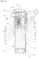
- FIG. 6 is a sectional view showing a cosmetic container having a hiding/revealing pump outlet according to the present invention.
- FIG. 7 is a cross-sectional view showing a state in which an outlet of a cosmetic container having a hiding/revealing pump outlet according to the present invention protrudes to the outside.
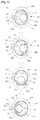
- FIG. 8 is a plan view showing a state in which a pressing member of a cosmetic container having a hiding/revealing pump outlet according to the present invention is rotated and causes an outlet of the pressing member to protrude out of an outlet hiding/revealing hole.
- FIG. 8 is a plan view showing a state in which a pressing member of a cosmetic container having a hiding/revealing pump outlet according to the present invention is rotated and causes an outlet of the pressing member to protrude out of an outlet hiding/
- FIG. 9 is a partial sectional view showing a state in which an outer container of a cosmetic container having a hiding/revealing pump outlet according to the present invention is rotated and causes a latching protrusion of an opening/closing member to extend over a latching sill.
- FIG. 10 is a sectional view showing a state in which a cosmetic material temporarily accommodated in the pump is discharged to the outside by pressing a cap cover of a cosmetic container having a hiding/revealing pump outlet according to the present invention.
- FIG. 11 is a sectional view showing a state in which a cosmetic material accommodated in an inner container is moved into the pump by releasing pressure on a cap cover of a cosmetic container having a hiding/revealing pump outlet according to the present invention.
- the cosmetic container having the hiding/revealing pump outlet includes: an outer container (10) formed at an upper portion thereof with an entrance (11); an inner container (20) inserted into the outer container (10) for accommodating a cosmetic material in the inner container (20); a pushing plate (30) inserted into an inner lower side of the inner container (20) to push up the cosmetic material; a first coupling body (40) fixed to an upper portion of the inner container (20), and having a pump installation hole (41) eccentrically formed in the first coupling body (40); a second coupling body (50) fixed to an upper portion of the first coupling body (40), and having a pump penetration hole (51) eccentrically formed in the second coupling body (50); a pump (60) installed through the pump installation hole (41) of the first coupling body (40) and the pump penetration hole (51) of the second coupling body (50) for pumping the cosmetic material; a pressing member (70) rotatably coupled to an upper portion of the pump (60) while being exposed on an upper portion of the second coupling body (50),
- the outer container (10) is formed in a cylindrical shape, and formed at an upper portion thereof with the entrance 11, in which a coupling protrusion wheel 12 is formed on an outer periphery of the entrance 11, thereby being coupled to the second coupling body (50).
- the inner container (20) is inserted inside the outer container (10), and the cosmetic material is accommodated in the inner container (20).
- a mounting groove 22 is formed on an upper inner periphery of the inner container (20), and an air inflow hole 21 into which external air flows is formed at a lower end of the inner container (20).
- a pushing plate (30) which moves upward by a discharged amount of the cosmetic material discharged to the outside by pumping is inserted into an inner lower portion of the inner container (20).
- the first coupling body (40) is fixed to the upper portion of the inner container (20), in which a lower portion of the first coupling body (40) is inserted into an upper side of the inner container (20).
- a pump installation hole (41) installed therein with the pump (60) is eccentrically formed in the first coupling body (40).
- a pair of fastening protrusions 42 protrude outward on an upper end of an outer periphery of the first coupling body (40) so as to be coupled to the second coupling body (50), and a mounting protrusion wheel 43 is formed on a lower outer periphery of the first coupling body (40) so as to be coupled to the mounting groove 22 of the inner container (20).
- a step 44 is formed on the outer periphery of the first coupling body (40) and seated on an upper end of the inner container (20).
- the second coupling body (50) is fixed to the upper portion of the first coupling body (40), while being coupled to an outer side of the entrance 11 of the outer container (10), and the pump penetration hole (51) which the pump (60) passes through is eccentrically formed.
- An outer lower extension protrusion wheel 56 and an inner lower extension protrusion wheel 57 inwardly spaced apart from the outer lower extension protrusion wheel 56 by a predetermined interval are formed at the lower portion of the second coupling body (50), in which the outer lower extension protrusion wheel 56 is formed on an inner periphery thereof with a coupling groove 561 to be coupled to the coupling protrusion wheel 12 of the outer container (10), and the inner lower extension protrusion wheel 57 is inserted into an inner upper portion of the first coupling body (40).
- a pair of fastening grooves 58 coupled to a fastening protrusion 42 of the first coupling body (40) are formed on an outer side of the second coupling body (50).
- the second coupling body (50) is formed on the outer side thereof with a rotation annular groove (59) to which the cap (80) and the opening/closing member (90) are rotatably coupled, and a rotation protrusion inserting groove 591 is formed at one side of the upper portion of the rotation annular groove (59).
- the rotation annular groove (59) includes a rotation protrusion rotating part 592 and a rotation protrusion restricting part 593, in which the rotation protrusion rotating part 592 is formed up to 180 degrees in the counterclockwise direction from the rotation protrusion inserting groove 591, and a depth of a groove of the rotation protrusion rotating part 592 is formed deeper than a depth of a groove of the rotation protrusion restricting part 593. Accordingly, rotation restricting sills 594 are formed at both ends of the rotation protrusion rotating part 592.
- a latching groove (52) is formed on an outer periphery of the second coupling body (50), and the latching sill (53) is formed adjacent to the latching groove (52).
- the second coupling body (50) is formed at the upper portion thereof with a first press prevention part (54) for preventing the pressing member (70) from being pressed due to a malfunction, and a first cap press prevention part (55) for preventing the cap cover (100) from being pressed due to a malfunction.
- the pump (60) is installed while passing through the pump installation hole (41) of the first coupling body (40) and the pump penetration hole (51) of the second coupling body (50), thereby serving to pump the cosmetic material accommodated in the inner container (20) so as to discharge the cosmetic material to the outside.
- the pump (60) is seated inside the pump installation hole (41) of the first coupling body (40), and includes a cylinder 61 formed therein with a content suction hole 68, a check valve 62 for selectively opening/closing the content suction hole 68, a sealing member 63 coupled to an upper portion of the cylinder 61 to seal the inside of the cylinder 61, a piston 64 formed inside the cylinder 61, a piston ring 65 fitted to an outside of the piston 64 to make close contact with an inner side surface of the cylinder 61, a vertical moving member 66 coupled to an upper portion of the piston 64, and an elastic member 67 for elastically supporting the vertical moving members 66.
- a sealing ring (69) may be further provided between the cylinder 61 of the pump (60) and the pump installation hole (41) of the first coupling body (40) to improve the sealing force inside the inner container (20).
- the pressing member (70) is rotatably coupled to an upper portion of the vertical moving member 66 of the pump (60) so as to be exposed on the upper portion of the second coupling body (50), and the pressing member (70) is formed at one side thereof with the outlet (71) through which the pumped cosmetic material is discharged.
- a second press prevention part 74 is formed below the outlet (71) of the pressing member (70) to prevent the pressing member (70) from being pressed due to a malfunction.
- the cap (80) is rotatably coupled to the upper portion of the second coupling body (50), and formed at one side thereof with the outlet hiding/revealing hole (81) which the outlet (71) of the pressing member (70) is inserted into or protrudes from.
- the cap (80) includes an outer wall 82 formed at one side thereof with the outlet hiding/revealing hole (81) and an inner wall 83 spaced apart from the outer wall 82 inward at a predetermined interval, and the cap guide groove 831 and the outlet penetration groove 832 are formed on the inner wall 83.
- the outlet penetration groove 832 of the inner wall 83 is formed at a position corresponding to the outlet hiding/revealing hole (81) formed in the outer wall 82.
- the rotation protrusion wheel 833 extends inward on the lower end of the inner wall 83 of the cap (80), and a rotation protrusion 834 further protrudes inward from one side of the rotation protrusion wheel 833, in which the rotation projection 834 is inserted into the rotation protrusion rotating part 592 of the rotation annular groove (59) through the rotation protrusion inserting groove 591 of the second coupling body (50), thereby rotating at 180 degrees in the clockwise or counterclockwise direction.
- the opening/closing member (90) rotatably coupled to the second coupling body (50) is further provided on the upper portion of the second coupling body (50).
- An opening/closing member rotation protrusion wheel 94 protrudes inward on an inner periphery of the opening/closing member (90), in which the opening/closing member rotation protrusion wheel 94 is fitted in the rotation annular groove (59) of the second coupling body (50) together with the rotation protrusion wheel 833 of the cap (80).
- the sliding door (91) extends from the upper side surface of the opening/closing member (90), in which the sliding door (91) of the opening/closing member (90) is rotated between the outer wall 82 and the inner wall 83 of the cap (80) to open or close the outlet hiding/revealing hole (81).
- An opening/closing protrusion 95 is formed on a lower inner periphery of the sliding door (91), and positioned below the outlet penetration groove 832 formed in the inner wall 83 of the cap (80) when assembled to the second coupling body (50) together with the cap (80).
- the latching protrusion (92) and the stopper (93) adjacent to the latching protrusion (92) are formed on the lower end of the side surface of the opening/closing member (90).
- the elastic groove (96) is formed on an upper side of the latching protrusion (92) of the opening/closing member (90) to enable the latching protrusion (92) to elastically move up and down.
- the opening/closing member (90) is also rotated simultaneously because the latching protrusion (92) of the opening/closing member (90) is inserted into the latching groove (52) of the second coupling body (50), so that the sliding door (91) of the opening/closing member (90) opens the outlet hiding/revealing hole (81) of the cap (80).
- the opening/closing protrusion 95 of the opening/closing member (90) makes contact with the outer side surface of the outlet penetration groove 832 of the cap (80), thus the rotation stops and the latching protrusion (92) of the opening/closing member (90) extends over the latching sill (53) of the second coupling body (50).
- the latching protrusion (92) of the opening/closing member (90) extends over the latching sill (53) of the second coupling body (50) and is fastened into the latching groove (52), so a blocked state of the outlet hiding/revealing hole (81) is confirmed by a sense of a hand together with a clicking sound.
- the cap (80) is further provided at an upper inner side thereof with the cap cover (100) for pressing the pressing member (70) while moving up and down.
- a vertical guide protrusion (101) coupled to the cap guide groove 831 of the cap (80) for guiding a vertical movement of the cap cover (100) is formed on an outer side of the cap cover (100), and a second cap press prevention part (102) extends downward to prevent the cap cover (100) from being pressed due to a malfunction.
- the pushing plate (30) is inserted into the inner container (20), the cosmetic material is accommodated therein, and then the inner container (20) is inserted into the outer container (10).
- the first coupling body (40) is inserted into and fixed to the upper end of the inner container (20), the pump (60) is installed in the pump installation hole (41) of the first coupling body (40), and then the second coupling body (50) is coupled to the upper portion of the first coupling body (40), in which the fastening protrusion 42 of the first coupling body (40) is coupled to the fastening groove 58 of the second coupling body (50), the inner lower extension protrusion wheel 57 of the second coupling body (50) is inserted inside the upper portion of the first coupling body (40), and the outer lower extension protrusion wheel 56 of the second coupling body (50) is fixe to the entrance 11 of the outer container (10).
- the pressing member (70) is rotatably coupled to the upper portion of the vertical moving member 66 of the pump (60), such that the second press prevention part 74 of the pressing member (70) abuts against the upper end of the first press prevention part (54) of the second coupling body (50).
- sealing ring (69) may be coupled between the pump installation hole (41) of the first coupling body (40) and the cylinder 61 of the pump (60) to improve the sealing force of the inner container (20).
- the opening/closing member (90) and the cap (80) are rotatably coupled to the upper portion of the second coupling body (50) assembled in the above manner, such that the opening/closing member rotation protrusion wheel 94 of the opening/closing member (90) and the rotation protrusion wheel 833 of the cap (80) are sequentially fitted into the rotation annular groove (59) of the second coupling body (50).
- the opening/closing member (90) is inserted between the outer wall 82 and the inner wall 83 of the cap (80), the sliding door (91) of the opening/closing member (90) is located between the outlet hiding/revealing hole (81) and the outlet penetration groove 832 of the cap (80), and the latching protrusion (92) of the opening/closing member (90) is inserted into the latching groove (52) of the second coupling body (50).
- the cap cover (100) is coupled to the upper inner side of the cap (80), in which the vertical guide protrusion (101) of the cap cover (100) is coupled to the cap guide groove 831 of the cap (80), and the second cap press prevention part (102) of the cap cover (100) abuts against the upper end of the first cap press prevention part (55) of the second coupling body (50), thus the assembly of the cosmetic container having the hiding/revealing pump outlet according to the present invention is completed.
- the cap (80) is held by one hand, and the outer container (10) is rotated at 180 degrees in the clockwise direction by the other hand.
- the inner container (10), the first coupling body (40) and the second coupling body (50) which are fixed to the outer container (10) are rotated together, and the pump (60) biasedly installed in the first and second coupling bodies (40) and (50) and the push button (70) coupled to the upper portion of the pump (60) are also rotated together.
- the sliding door (91) of the opening/closing member (90) is rotated to open the outlet hiding/revealing hole (81) of the cap (80), the outlet (71) of the push button (70) starts to protrude to the outside through the outlet hiding/revealing hole (81) of the cap (80) as shown in the second drawing of FIG. 8 , and the outlet (71) of the push button (70) completely protrudes from the outlet hiding/revealing hole (81) of the cap (80) as shown in the fourth drawing of FIG. 8 .
- the push button (70) and the cap cover (100) are put in a state to be pressed.
- the push button (70) making close contact with the lower surface of the cap cover (100) moves downward to pump the pump (60) by pressing the cap cover (100), thus the contents are discharged to the outlet (71) for use.
- the opening/closing protrusion 95 of the opening/closing member (90) makes contact with the outer side surface of the outlet penetration groove 832 of the cap (80), thus the rotation stops and the latching protrusion (92) of the opening/closing member (90) extends over the latching sill (53) of the second coupling body (50) as shown in FIG. 9 .
- the first press prevention part (54) of the second coupling body (50) is rotated to be prevented from abutting against the second press prevention part 74 of the pressing member (70), and the first cap press prevention part (55) of the second coupling body (50) is rotated to be prevented from abutting against the second cap press prevention part (102) of the cap cover (100), so that the push button (70) and the cap cover (100) are put in a state to be pressed.
- the inner container (10), the first coupling body (40) and the second coupling body (50) which are fixed to the outer container (10) are rotated together, and the pump (60) biasedly installed in the first and second coupling bodies (40) and (50) and the push button (70) coupled to the upper portion of the pump (60) are also rotated together.
- the outlet (71) of the push button (70) is inserted into the cap (80), the sliding door (91) of the opening/closing member (90) closes the outlet hiding/revealing hole (81) of the cap (80), and the push button (70) and the cap cover (100) are put in a state which is not pressed.
- the latching protrusion (92) of the opening/closing member (90) is latched to the latching sill (53) of the second coupling body (50), thus the opening/closing member (90) is rotated together with the second coupling body (50), thereby rotating the sliding door (91) of the opening/closing member (90) to close the outlet hiding/revealing hole (81) of the cap (80).
- the latching protrusion (92) of the opening/closing member (90) extends over the latching sill (53) of the second coupling body (50) and is fastened into the latching groove (52).
- the first press prevention part (54) of the second coupling body (50) is rotated to abut against the lower portion of the second press prevention part 74 of the pressing member (70), and the first cap press prevention part (55) of the second coupling body (50) is rotated to abut against the lower portion of the second cap press prevention part (102) of the cap cover (100), thus the push button (70) and the cap cover (100) are put in a state which is not pressed.
Claims (5)
- Ein Kosmetikbehälter mit einem versteckbaren/enthüllbaren Pumpenauslass, wobei der Kosmetikbehälter umfasst:einen äußeren Behälter (10), der an einem oberen Abschnitt davon mit einem Eingang (11) ausgebildet ist; einen inneren Behälter (20), der in den äußeren Behälter (10) zur Aufnahme eines kosmetischen Materials im Innenbehälter (20);einen ersten Kupplungskörper (40), der an einem oberen Abschnitt des Innenbehälters (20) befestigt ist und ein Pumpeninstallationsloch (41) aufweist, das exzentrisch in dem ersten Kupplungskörper (40) ausgebildet ist;einen zweiten Kupplungskörper (50), der an einem oberen Abschnitt des ersten Kupplungskörpers (40) befestigt ist und ein Pumpendurchgangsloch (51) aufweist, das exzentrisch in dem zweiten Kupplungskörper (50) ausgebildet ist;eine Pumpe (60), die zum Pumpen des kosmetischen Materials durch das Pumpeninstallationsloch (41) des ersten Kupplungskörpers (40) und das Pumpendurchgangsloch (51) des zweiten Kupplungskörpers (50) eingebaut ist;ein Druckelement (70), das drehbar mit einem oberen Abschnitt der Pumpe (60) gekoppelt ist, während es an einem oberen Abschnitt des zweiten Kupplungskörpers (50) freiliegt, und an einer Seite davon mit einem Auslass (71) ausgebildet ist; undeine Kappe (80), die drehbar mit dem oberen Teil des zweiten Kupplungskörpers (50) verbunden ist, und an einer Seite davon mit einer Auslassöffnung zum Verbergen/Enthüllen (81) ausgebildet ist.
- Kosmetikbehälter nach Anspruch 1, der ferner ein Öffnungs-/Schließglied (90) umfasst, das drehbar mit dem oberen Teil des zweiten Kupplungskörpers (50) gekoppelt ist, wobei eine Schiebetür (91) zum Öffnen/Schließen der Auslassöffnung zum Verbergen/Enthüllen (81) der Kappe (80) erstreckt sich von einer oberen Seitenfläche des Öffnungs-/Schließelements (90).
- Kosmetikbehälter nach Anspruch 2, wobei das Öffnungs-/Schließteil (90) an einem unteren Ende seiner Seitenfläche mit einem Einrastvorsprung (92) und einem Stopfen (93) neben dem Einrastvorsprung (92) ausgebildet ist.
- Kosmetikbehälter nach Anspruch 1, wobei der zweite Kupplungskörper (50) an seinem Außenumfang mit einer Einrastnut (52) und einer an die Einrastnut (52) angrenzenden Einrastschwelle (53) ausgebildet ist.
- Kosmetikbehälter nach Anspruch 1, bei dem ein erstes Pressverhinderungsteil (54) am oberen Abschnitt des zweiten Kupplungskörpers (50) und ein zweites Pressverhinderungsteil (74) an einer Unterseite des Auslasses (71) des Pressteils ausgebildet ist (70).
Applications Claiming Priority (2)
| Application Number | Priority Date | Filing Date | Title |
|---|---|---|---|
| KR2020150003227U KR200483952Y1 (ko) | 2015-05-20 | 2015-05-20 | 펌프의 토출구가 출몰되는 화장품 용기 |
| PCT/KR2016/004850 WO2016186357A1 (ko) | 2015-05-20 | 2016-05-10 | 펌프의 토출구가 출몰되는 화장품 용기 |
Publications (3)
| Publication Number | Publication Date |
|---|---|
| EP3287039A1 EP3287039A1 (de) | 2018-02-28 |
| EP3287039A4 EP3287039A4 (de) | 2018-04-25 |
| EP3287039B1 true EP3287039B1 (de) | 2020-04-01 |
Family
ID=57318905
Family Applications (1)
| Application Number | Title | Priority Date | Filing Date |
|---|---|---|---|
| EP16796684.5A Active EP3287039B1 (de) | 2015-05-20 | 2016-05-10 | Kosmetikbehälter mit verborgenem/offengelegtem pumpenausgang |
Country Status (6)
| Country | Link |
|---|---|
| US (1) | US10293356B2 (de) |
| EP (1) | EP3287039B1 (de) |
| JP (1) | JP6585194B2 (de) |
| KR (1) | KR200483952Y1 (de) |
| CN (1) | CN208436405U (de) |
| WO (1) | WO2016186357A1 (de) |
Families Citing this family (20)
| Publication number | Priority date | Publication date | Assignee | Title |
|---|---|---|---|---|
| KR200483952Y1 (ko) * | 2015-05-20 | 2017-07-27 | 펌텍코리아 (주) | 펌프의 토출구가 출몰되는 화장품 용기 |
| USD856814S1 (en) * | 2015-07-10 | 2019-08-20 | HCT Group Holdings Limited | Combined cosmetics dispenser and applicator |
| CN207684093U (zh) * | 2017-06-14 | 2018-08-03 | 浙江锦盛新材料股份有限公司 | 一种按头旋转伸缩真空瓶 |
| KR102016853B1 (ko) * | 2018-05-01 | 2019-10-21 | 강성일 | 화장품용 버튼용기 |
| US10335816B1 (en) | 2018-08-29 | 2019-07-02 | Armin Arminak | All plastic water resistant pump |
| USD947033S1 (en) * | 2018-09-24 | 2022-03-29 | Modafino, LLC | Dispenser system |
| US11278100B2 (en) | 2019-01-07 | 2022-03-22 | Xuyoni Co., Ltd. | Triangular container for cosmetics |
| KR102058251B1 (ko) * | 2019-06-14 | 2020-01-22 | 배주연 | 화장품용 삼각 용기 |
| KR102169977B1 (ko) * | 2019-02-20 | 2020-10-26 | 펌텍코리아(주) | 밀폐 기능이 향상된 화장품 용기 |
| KR102120247B1 (ko) * | 2019-03-22 | 2020-06-17 | 펌텍코리아(주) | 밀폐 및 편의성이 향상된 화장품 용기 |
| DE202019103061U1 (de) * | 2019-05-29 | 2020-09-01 | Louvrette Gmbh Design X Packaging | Vorrichtung zur Aufbewahrung und Abgabe einer flüssigen oder pastösen Masse |
| KR20210005426A (ko) * | 2019-07-05 | 2021-01-14 | 펌텍코리아 (주) | 편리한 리필 구조를 갖는 화장품 용기 |
| US10781033B1 (en) | 2019-10-29 | 2020-09-22 | APC Packaging, LLC | Reusable bottle package |
| US10829271B1 (en) | 2019-11-18 | 2020-11-10 | APC Packaging, LLC. | Replaceable jar package |
| USD991785S1 (en) | 2020-01-31 | 2023-07-11 | Armin Arminak | Lotion pump actuator |
| US11084646B1 (en) * | 2020-03-20 | 2021-08-10 | Crystal International (Group) | Refillable pump dispenser |
| CN111409948B (zh) * | 2020-03-30 | 2021-09-28 | 浙江万升化妆品包装有限公司 | 一种化妆瓶包装机构 |
| EP3974345A1 (de) * | 2020-09-28 | 2022-03-30 | Aptar Radolfzell GmbH | Sprühkopf und spender mit einem solchen sprühkopf |
| KR102456614B1 (ko) * | 2021-01-15 | 2022-10-19 | 펌텍코리아(주) | 버튼의 승강 구조를 갖는 이중 화장품용기 |
| US20230092170A1 (en) * | 2021-09-23 | 2023-03-23 | Apackaging Group Llc | All Plastic High Pressure Pump |
Family Cites Families (17)
| Publication number | Priority date | Publication date | Assignee | Title |
|---|---|---|---|---|
| WO1987006503A1 (en) * | 1986-04-25 | 1987-11-05 | Japan Gas Co. Ltd. | Spray head with protective cap |
| US4998649A (en) * | 1987-07-27 | 1991-03-12 | Thanisch Klaus J | Retractable turnspout closure |
| US4836423A (en) * | 1988-04-26 | 1989-06-06 | Anchor Hocking Corporation | Pump dispenser package |
| US5016783A (en) * | 1988-04-26 | 1991-05-21 | Anchor Hocking Corporation | Pump dispenser package |
| FR2692232B1 (fr) * | 1992-06-12 | 1994-08-26 | Reboul Smt | Pot distributeur-doseur de substance fluide. |
| US5579948A (en) * | 1995-10-26 | 1996-12-03 | Shing Hong Industrial Co., Ltd. | Beverage container with extendable drinking straw |
| KR200310095Y1 (ko) | 2002-10-09 | 2003-04-08 | 강성일 | 뚜껑이 불필요한 출몰식 배출장치를 갖는 화장품 케이스 |
| KR200347811Y1 (ko) | 2003-12-05 | 2004-04-17 | 주식회사 태평양 | 출몰식 화장품 용기 |
| KR200425584Y1 (ko) * | 2006-06-26 | 2006-09-06 | 김규진 | 화장품용기의 뚜껑회전식 노즐 개폐장치 |
| KR200428274Y1 (ko) * | 2006-07-19 | 2006-10-12 | (주)연우 | 디스펜서 용기 |
| FR2908116B1 (fr) * | 2006-11-06 | 2012-07-13 | Valois Sas | Distributeur de produit fluide |
| EP2342990A4 (de) * | 2008-10-20 | 2013-09-18 | Jae-Sam Byeon | Luftloser kosmetikbehälter |
| FR2959215B1 (fr) * | 2010-04-22 | 2013-09-06 | Qualipac Sa | Distributeur de produit fluide a tete escamotable |
| KR101218741B1 (ko) * | 2010-12-03 | 2013-01-07 | (주)연우 | 디스펜서 용기 |
| KR101267966B1 (ko) | 2011-05-24 | 2013-05-27 | (주)톨리코리아 | 출몰식 작동버튼을 가지는 에어리스 펌프 화장품용기 |
| KR101488673B1 (ko) * | 2014-01-15 | 2015-02-04 | (주)연우 | 노즐 출몰식 화장품 용기 |
| KR200483952Y1 (ko) * | 2015-05-20 | 2017-07-27 | 펌텍코리아 (주) | 펌프의 토출구가 출몰되는 화장품 용기 |
-
2015
- 2015-05-20 KR KR2020150003227U patent/KR200483952Y1/ko active IP Right Grant
-
2016
- 2016-05-10 WO PCT/KR2016/004850 patent/WO2016186357A1/ko active Application Filing
- 2016-05-10 CN CN201690000826.0U patent/CN208436405U/zh active Active
- 2016-05-10 US US15/572,104 patent/US10293356B2/en active Active
- 2016-05-10 EP EP16796684.5A patent/EP3287039B1/de active Active
- 2016-05-10 JP JP2017560249A patent/JP6585194B2/ja active Active
Non-Patent Citations (1)
| Title |
|---|
| None * |
Also Published As
| Publication number | Publication date |
|---|---|
| JP6585194B2 (ja) | 2019-10-02 |
| CN208436405U (zh) | 2019-01-29 |
| KR20160004122U (ko) | 2016-12-01 |
| KR200483952Y1 (ko) | 2017-07-27 |
| EP3287039A1 (de) | 2018-02-28 |
| EP3287039A4 (de) | 2018-04-25 |
| US10293356B2 (en) | 2019-05-21 |
| US20180290161A1 (en) | 2018-10-11 |
| WO2016186357A1 (ko) | 2016-11-24 |
| JP2018516662A (ja) | 2018-06-28 |
Similar Documents
| Publication | Publication Date | Title |
|---|---|---|
| EP3287039B1 (de) | Kosmetikbehälter mit verborgenem/offengelegtem pumpenausgang | |
| EP3078295B1 (de) | Kosmetikbehälter mit lösbar an der seite eines knopfelements befestigtem auftragselement | |
| JP3725190B2 (ja) | 一方向性の閉鎖部材が取り付けられた分与アセンブリ | |
| US20080169312A1 (en) | Dispenser with Sealed Dispensing Valve Unit | |
| JP2021010737A (ja) | 便利なリフィル構造を有する化粧品容器 | |
| JP2003312699A (ja) | 容 器 | |
| KR200361671Y1 (ko) | 화장 크림 용기 | |
| US20200376509A1 (en) | Cosmetic container having push button blocked from being pushed within regulation angle | |
| EP3711626A1 (de) | Kosmetikbehälter mit pumpe mit einem teil aus polyketonmaterial | |
| KR101765711B1 (ko) | 회전 개폐형 유입방지부재를 구비한 펌프용기 | |
| KR102609420B1 (ko) | 액상 내용물 토출 용기 | |
| KR200485890Y1 (ko) | 고무링이 삽입된 스크류 타입 에어리스 펌프 용기 | |
| KR102549913B1 (ko) | 튜브형 액상 내용물 토출 용기 | |
| KR102499659B1 (ko) | 리필 구조를 갖는 화장품 케이스 | |
| JP4610256B2 (ja) | 定量注出器 | |
| KR102636711B1 (ko) | 가압 토출 용기 | |
| KR102518506B1 (ko) | 회전 토출형 화장품 용기 | |
| EP4357268A1 (de) | Behälter zum entleeren von flüssigen inhalten | |
| KR101512431B1 (ko) | 펌핑용기 | |
| US11365813B2 (en) | Device for selectively storing and mixing first and second liquids | |
| KR200255127Y1 (ko) | 에어리스 펌프타입 화장품 용기의 내용물 토출구조 | |
| KR20080001987U (ko) | 립스틱을 구비한 립글로스 용기 | |
| JP2003300571A (ja) | エアゾール製品の噴射方法および該噴射方法に用いるエアゾール製品 |
Legal Events
| Date | Code | Title | Description |
|---|---|---|---|
| STAA | Information on the status of an ep patent application or granted ep patent |
Free format text: STATUS: THE INTERNATIONAL PUBLICATION HAS BEEN MADE |
|
| PUAI | Public reference made under article 153(3) epc to a published international application that has entered the european phase |
Free format text: ORIGINAL CODE: 0009012 |
|
| STAA | Information on the status of an ep patent application or granted ep patent |
Free format text: STATUS: REQUEST FOR EXAMINATION WAS MADE |
|
| 17P | Request for examination filed |
Effective date: 20171120 |
|
| AK | Designated contracting states |
Kind code of ref document: A1 Designated state(s): AL AT BE BG CH CY CZ DE DK EE ES FI FR GB GR HR HU IE IS IT LI LT LU LV MC MK MT NL NO PL PT RO RS SE SI SK SM TR |
|
| AX | Request for extension of the european patent |
Extension state: BA ME |
|
| A4 | Supplementary search report drawn up and despatched |
Effective date: 20180327 |
|
| RIC1 | Information provided on ipc code assigned before grant |
Ipc: A45D 34/00 20060101ALI20180321BHEP Ipc: A45D 40/00 20060101ALI20180321BHEP Ipc: B05B 11/00 20060101AFI20180321BHEP |
|
| DAV | Request for validation of the european patent (deleted) | ||
| DAX | Request for extension of the european patent (deleted) | ||
| REG | Reference to a national code |
Ref country code: DE Ref legal event code: R079 Ref document number: 602016033168 Country of ref document: DE Free format text: PREVIOUS MAIN CLASS: A45D0040000000 Ipc: B05B0011000000 |
|
| RIC1 | Information provided on ipc code assigned before grant |
Ipc: A45D 40/00 20060101ALI20190919BHEP Ipc: A45D 34/00 20060101ALI20190919BHEP Ipc: B05B 11/00 20060101AFI20190919BHEP |
|
| GRAP | Despatch of communication of intention to grant a patent |
Free format text: ORIGINAL CODE: EPIDOSNIGR1 |
|
| STAA | Information on the status of an ep patent application or granted ep patent |
Free format text: STATUS: GRANT OF PATENT IS INTENDED |
|
| INTG | Intention to grant announced |
Effective date: 20191025 |
|
| GRAS | Grant fee paid |
Free format text: ORIGINAL CODE: EPIDOSNIGR3 |
|
| GRAA | (expected) grant |
Free format text: ORIGINAL CODE: 0009210 |
|
| STAA | Information on the status of an ep patent application or granted ep patent |
Free format text: STATUS: THE PATENT HAS BEEN GRANTED |
|
| AK | Designated contracting states |
Kind code of ref document: B1 Designated state(s): AL AT BE BG CH CY CZ DE DK EE ES FI FR GB GR HR HU IE IS IT LI LT LU LV MC MK MT NL NO PL PT RO RS SE SI SK SM TR |
|
| REG | Reference to a national code |
Ref country code: GB Ref legal event code: FG4D |
|
| REG | Reference to a national code |
Ref country code: CH Ref legal event code: EP Ref country code: AT Ref legal event code: REF Ref document number: 1250692 Country of ref document: AT Kind code of ref document: T Effective date: 20200415 |
|
| REG | Reference to a national code |
Ref country code: DE Ref legal event code: R096 Ref document number: 602016033168 Country of ref document: DE |
|
| REG | Reference to a national code |
Ref country code: IE Ref legal event code: FG4D |
|
| PG25 | Lapsed in a contracting state [announced via postgrant information from national office to epo] |
Ref country code: BG Free format text: LAPSE BECAUSE OF FAILURE TO SUBMIT A TRANSLATION OF THE DESCRIPTION OR TO PAY THE FEE WITHIN THE PRESCRIBED TIME-LIMIT Effective date: 20200701 |
|
| REG | Reference to a national code |
Ref country code: NL Ref legal event code: MP Effective date: 20200401 |
|
| REG | Reference to a national code |
Ref country code: LT Ref legal event code: MG4D |
|
| PG25 | Lapsed in a contracting state [announced via postgrant information from national office to epo] |
Ref country code: GR Free format text: LAPSE BECAUSE OF FAILURE TO SUBMIT A TRANSLATION OF THE DESCRIPTION OR TO PAY THE FEE WITHIN THE PRESCRIBED TIME-LIMIT Effective date: 20200702 Ref country code: NO Free format text: LAPSE BECAUSE OF FAILURE TO SUBMIT A TRANSLATION OF THE DESCRIPTION OR TO PAY THE FEE WITHIN THE PRESCRIBED TIME-LIMIT Effective date: 20200701 Ref country code: FI Free format text: LAPSE BECAUSE OF FAILURE TO SUBMIT A TRANSLATION OF THE DESCRIPTION OR TO PAY THE FEE WITHIN THE PRESCRIBED TIME-LIMIT Effective date: 20200401 Ref country code: PT Free format text: LAPSE BECAUSE OF FAILURE TO SUBMIT A TRANSLATION OF THE DESCRIPTION OR TO PAY THE FEE WITHIN THE PRESCRIBED TIME-LIMIT Effective date: 20200817 Ref country code: LT Free format text: LAPSE BECAUSE OF FAILURE TO SUBMIT A TRANSLATION OF THE DESCRIPTION OR TO PAY THE FEE WITHIN THE PRESCRIBED TIME-LIMIT Effective date: 20200401 Ref country code: IS Free format text: LAPSE BECAUSE OF FAILURE TO SUBMIT A TRANSLATION OF THE DESCRIPTION OR TO PAY THE FEE WITHIN THE PRESCRIBED TIME-LIMIT Effective date: 20200801 Ref country code: SE Free format text: LAPSE BECAUSE OF FAILURE TO SUBMIT A TRANSLATION OF THE DESCRIPTION OR TO PAY THE FEE WITHIN THE PRESCRIBED TIME-LIMIT Effective date: 20200401 Ref country code: CZ Free format text: LAPSE BECAUSE OF FAILURE TO SUBMIT A TRANSLATION OF THE DESCRIPTION OR TO PAY THE FEE WITHIN THE PRESCRIBED TIME-LIMIT Effective date: 20200401 Ref country code: NL Free format text: LAPSE BECAUSE OF FAILURE TO SUBMIT A TRANSLATION OF THE DESCRIPTION OR TO PAY THE FEE WITHIN THE PRESCRIBED TIME-LIMIT Effective date: 20200401 |
|
| REG | Reference to a national code |
Ref country code: AT Ref legal event code: MK05 Ref document number: 1250692 Country of ref document: AT Kind code of ref document: T Effective date: 20200401 |
|
| PG25 | Lapsed in a contracting state [announced via postgrant information from national office to epo] |
Ref country code: RS Free format text: LAPSE BECAUSE OF FAILURE TO SUBMIT A TRANSLATION OF THE DESCRIPTION OR TO PAY THE FEE WITHIN THE PRESCRIBED TIME-LIMIT Effective date: 20200401 Ref country code: LV Free format text: LAPSE BECAUSE OF FAILURE TO SUBMIT A TRANSLATION OF THE DESCRIPTION OR TO PAY THE FEE WITHIN THE PRESCRIBED TIME-LIMIT Effective date: 20200401 Ref country code: HR Free format text: LAPSE BECAUSE OF FAILURE TO SUBMIT A TRANSLATION OF THE DESCRIPTION OR TO PAY THE FEE WITHIN THE PRESCRIBED TIME-LIMIT Effective date: 20200401 |
|
| REG | Reference to a national code |
Ref country code: DE Ref legal event code: R119 Ref document number: 602016033168 Country of ref document: DE |
|
| PG25 | Lapsed in a contracting state [announced via postgrant information from national office to epo] |
Ref country code: AL Free format text: LAPSE BECAUSE OF FAILURE TO SUBMIT A TRANSLATION OF THE DESCRIPTION OR TO PAY THE FEE WITHIN THE PRESCRIBED TIME-LIMIT Effective date: 20200401 |
|
| PG25 | Lapsed in a contracting state [announced via postgrant information from national office to epo] |
Ref country code: MC Free format text: LAPSE BECAUSE OF FAILURE TO SUBMIT A TRANSLATION OF THE DESCRIPTION OR TO PAY THE FEE WITHIN THE PRESCRIBED TIME-LIMIT Effective date: 20200401 Ref country code: ES Free format text: LAPSE BECAUSE OF FAILURE TO SUBMIT A TRANSLATION OF THE DESCRIPTION OR TO PAY THE FEE WITHIN THE PRESCRIBED TIME-LIMIT Effective date: 20200401 Ref country code: DK Free format text: LAPSE BECAUSE OF FAILURE TO SUBMIT A TRANSLATION OF THE DESCRIPTION OR TO PAY THE FEE WITHIN THE PRESCRIBED TIME-LIMIT Effective date: 20200401 Ref country code: EE Free format text: LAPSE BECAUSE OF FAILURE TO SUBMIT A TRANSLATION OF THE DESCRIPTION OR TO PAY THE FEE WITHIN THE PRESCRIBED TIME-LIMIT Effective date: 20200401 Ref country code: SM Free format text: LAPSE BECAUSE OF FAILURE TO SUBMIT A TRANSLATION OF THE DESCRIPTION OR TO PAY THE FEE WITHIN THE PRESCRIBED TIME-LIMIT Effective date: 20200401 Ref country code: IT Free format text: LAPSE BECAUSE OF FAILURE TO SUBMIT A TRANSLATION OF THE DESCRIPTION OR TO PAY THE FEE WITHIN THE PRESCRIBED TIME-LIMIT Effective date: 20200401 Ref country code: AT Free format text: LAPSE BECAUSE OF FAILURE TO SUBMIT A TRANSLATION OF THE DESCRIPTION OR TO PAY THE FEE WITHIN THE PRESCRIBED TIME-LIMIT Effective date: 20200401 Ref country code: LI Free format text: LAPSE BECAUSE OF NON-PAYMENT OF DUE FEES Effective date: 20200531 Ref country code: RO Free format text: LAPSE BECAUSE OF FAILURE TO SUBMIT A TRANSLATION OF THE DESCRIPTION OR TO PAY THE FEE WITHIN THE PRESCRIBED TIME-LIMIT Effective date: 20200401 Ref country code: CH Free format text: LAPSE BECAUSE OF NON-PAYMENT OF DUE FEES Effective date: 20200531 |
|
| PLBE | No opposition filed within time limit |
Free format text: ORIGINAL CODE: 0009261 |
|
| STAA | Information on the status of an ep patent application or granted ep patent |
Free format text: STATUS: NO OPPOSITION FILED WITHIN TIME LIMIT |
|
| PG25 | Lapsed in a contracting state [announced via postgrant information from national office to epo] |
Ref country code: PL Free format text: LAPSE BECAUSE OF FAILURE TO SUBMIT A TRANSLATION OF THE DESCRIPTION OR TO PAY THE FEE WITHIN THE PRESCRIBED TIME-LIMIT Effective date: 20200401 Ref country code: SK Free format text: LAPSE BECAUSE OF FAILURE TO SUBMIT A TRANSLATION OF THE DESCRIPTION OR TO PAY THE FEE WITHIN THE PRESCRIBED TIME-LIMIT Effective date: 20200401 |
|
| 26N | No opposition filed |
Effective date: 20210112 |
|
| REG | Reference to a national code |
Ref country code: BE Ref legal event code: MM Effective date: 20200531 |
|
| GBPC | Gb: european patent ceased through non-payment of renewal fee |
Effective date: 20200701 |
|
| PG25 | Lapsed in a contracting state [announced via postgrant information from national office to epo] |
Ref country code: LU Free format text: LAPSE BECAUSE OF NON-PAYMENT OF DUE FEES Effective date: 20200510 |
|
| PG25 | Lapsed in a contracting state [announced via postgrant information from national office to epo] |
Ref country code: IE Free format text: LAPSE BECAUSE OF NON-PAYMENT OF DUE FEES Effective date: 20200510 Ref country code: GB Free format text: LAPSE BECAUSE OF NON-PAYMENT OF DUE FEES Effective date: 20200701 |
|
| PG25 | Lapsed in a contracting state [announced via postgrant information from national office to epo] |
Ref country code: BE Free format text: LAPSE BECAUSE OF NON-PAYMENT OF DUE FEES Effective date: 20200531 Ref country code: DE Free format text: LAPSE BECAUSE OF NON-PAYMENT OF DUE FEES Effective date: 20201201 Ref country code: SI Free format text: LAPSE BECAUSE OF FAILURE TO SUBMIT A TRANSLATION OF THE DESCRIPTION OR TO PAY THE FEE WITHIN THE PRESCRIBED TIME-LIMIT Effective date: 20200401 |
|
| PG25 | Lapsed in a contracting state [announced via postgrant information from national office to epo] |
Ref country code: TR Free format text: LAPSE BECAUSE OF FAILURE TO SUBMIT A TRANSLATION OF THE DESCRIPTION OR TO PAY THE FEE WITHIN THE PRESCRIBED TIME-LIMIT Effective date: 20200401 Ref country code: MT Free format text: LAPSE BECAUSE OF FAILURE TO SUBMIT A TRANSLATION OF THE DESCRIPTION OR TO PAY THE FEE WITHIN THE PRESCRIBED TIME-LIMIT Effective date: 20200401 Ref country code: CY Free format text: LAPSE BECAUSE OF FAILURE TO SUBMIT A TRANSLATION OF THE DESCRIPTION OR TO PAY THE FEE WITHIN THE PRESCRIBED TIME-LIMIT Effective date: 20200401 |
|
| PG25 | Lapsed in a contracting state [announced via postgrant information from national office to epo] |
Ref country code: MK Free format text: LAPSE BECAUSE OF FAILURE TO SUBMIT A TRANSLATION OF THE DESCRIPTION OR TO PAY THE FEE WITHIN THE PRESCRIBED TIME-LIMIT Effective date: 20200401 |
|
| PGFP | Annual fee paid to national office [announced via postgrant information from national office to epo] |
Ref country code: FR Payment date: 20230524 Year of fee payment: 8 |