EP3286576B1 - Funkfrequenzdetektion mit mehreren sensoren - Google Patents
Funkfrequenzdetektion mit mehreren sensoren Download PDFInfo
- Publication number
- EP3286576B1 EP3286576B1 EP16722062.3A EP16722062A EP3286576B1 EP 3286576 B1 EP3286576 B1 EP 3286576B1 EP 16722062 A EP16722062 A EP 16722062A EP 3286576 B1 EP3286576 B1 EP 3286576B1
- Authority
- EP
- European Patent Office
- Prior art keywords
- radio frequency
- motion sensor
- physiological motion
- sensors
- sensor
- Prior art date
- Legal status (The legal status is an assumption and is not a legal conclusion. Google has not performed a legal analysis and makes no representation as to the accuracy of the status listed.)
- Active
Links
- 238000001514 detection method Methods 0.000 title claims description 25
- 230000033001 locomotion Effects 0.000 claims description 223
- 230000002452 interceptive effect Effects 0.000 claims description 36
- 230000001360 synchronised effect Effects 0.000 claims description 30
- 230000005540 biological transmission Effects 0.000 claims description 22
- 230000008859 change Effects 0.000 claims description 19
- 230000000694 effects Effects 0.000 claims description 17
- 230000004044 response Effects 0.000 claims description 15
- 230000029058 respiratory gaseous exchange Effects 0.000 claims description 14
- 230000000747 cardiac effect Effects 0.000 claims description 11
- 230000000737 periodic effect Effects 0.000 claims description 10
- 230000003595 spectral effect Effects 0.000 claims description 7
- 230000000241 respiratory effect Effects 0.000 claims description 6
- 238000004458 analytical method Methods 0.000 claims description 3
- 230000005541 medical transmission Effects 0.000 claims description 2
- 238000005516 engineering process Methods 0.000 description 47
- 238000000034 method Methods 0.000 description 30
- 238000004891 communication Methods 0.000 description 16
- 230000009467 reduction Effects 0.000 description 12
- 239000013078 crystal Substances 0.000 description 10
- 230000008569 process Effects 0.000 description 8
- 238000010586 diagram Methods 0.000 description 7
- 230000006870 function Effects 0.000 description 7
- 238000012545 processing Methods 0.000 description 7
- 239000010453 quartz Substances 0.000 description 7
- 230000002829 reductive effect Effects 0.000 description 7
- VYPSYNLAJGMNEJ-UHFFFAOYSA-N silicon dioxide Inorganic materials O=[Si]=O VYPSYNLAJGMNEJ-UHFFFAOYSA-N 0.000 description 7
- 230000008901 benefit Effects 0.000 description 6
- 239000000463 material Substances 0.000 description 5
- 239000000919 ceramic Substances 0.000 description 4
- 230000001419 dependent effect Effects 0.000 description 4
- 230000010355 oscillation Effects 0.000 description 4
- 230000035479 physiological effects, processes and functions Effects 0.000 description 4
- 230000007958 sleep Effects 0.000 description 4
- 238000013459 approach Methods 0.000 description 3
- 230000006399 behavior Effects 0.000 description 3
- 238000012937 correction Methods 0.000 description 3
- 238000001914 filtration Methods 0.000 description 3
- 238000002955 isolation Methods 0.000 description 3
- 230000008933 bodily movement Effects 0.000 description 2
- 239000003990 capacitor Substances 0.000 description 2
- 230000003111 delayed effect Effects 0.000 description 2
- 230000001066 destructive effect Effects 0.000 description 2
- 238000002592 echocardiography Methods 0.000 description 2
- 230000001105 regulatory effect Effects 0.000 description 2
- 238000005070 sampling Methods 0.000 description 2
- 238000012360 testing method Methods 0.000 description 2
- 241001465754 Metazoa Species 0.000 description 1
- 230000004888 barrier function Effects 0.000 description 1
- 230000035559 beat frequency Effects 0.000 description 1
- 230000002802 cardiorespiratory effect Effects 0.000 description 1
- 230000002079 cooperative effect Effects 0.000 description 1
- 230000008878 coupling Effects 0.000 description 1
- 238000010168 coupling process Methods 0.000 description 1
- 238000005859 coupling reaction Methods 0.000 description 1
- 230000001934 delay Effects 0.000 description 1
- 238000013461 design Methods 0.000 description 1
- 239000003989 dielectric material Substances 0.000 description 1
- 230000003467 diminishing effect Effects 0.000 description 1
- 239000000835 fiber Substances 0.000 description 1
- 238000009434 installation Methods 0.000 description 1
- 238000004519 manufacturing process Methods 0.000 description 1
- 230000000116 mitigating effect Effects 0.000 description 1
- 239000000203 mixture Substances 0.000 description 1
- 238000012986 modification Methods 0.000 description 1
- 230000004048 modification Effects 0.000 description 1
- 238000012544 monitoring process Methods 0.000 description 1
- 230000006855 networking Effects 0.000 description 1
- 231100000989 no adverse effect Toxicity 0.000 description 1
- 238000001208 nuclear magnetic resonance pulse sequence Methods 0.000 description 1
- 230000000474 nursing effect Effects 0.000 description 1
- 238000005457 optimization Methods 0.000 description 1
- 230000003071 parasitic effect Effects 0.000 description 1
- 230000000149 penetrating effect Effects 0.000 description 1
- 230000000717 retained effect Effects 0.000 description 1
- 238000010079 rubber tapping Methods 0.000 description 1
- 230000035945 sensitivity Effects 0.000 description 1
- 238000000926 separation method Methods 0.000 description 1
- 230000008054 signal transmission Effects 0.000 description 1
- 238000001228 spectrum Methods 0.000 description 1
- 230000002459 sustained effect Effects 0.000 description 1
- 238000010408 sweeping Methods 0.000 description 1
- 230000036962 time dependent Effects 0.000 description 1
- 238000012876 topography Methods 0.000 description 1
Images


Classifications
-
- A—HUMAN NECESSITIES
- A61—MEDICAL OR VETERINARY SCIENCE; HYGIENE
- A61B—DIAGNOSIS; SURGERY; IDENTIFICATION
- A61B5/00—Measuring for diagnostic purposes; Identification of persons
- A61B5/02—Detecting, measuring or recording pulse, heart rate, blood pressure or blood flow; Combined pulse/heart-rate/blood pressure determination; Evaluating a cardiovascular condition not otherwise provided for, e.g. using combinations of techniques provided for in this group with electrocardiography or electroauscultation; Heart catheters for measuring blood pressure
- A61B5/024—Detecting, measuring or recording pulse rate or heart rate
- A61B5/02444—Details of sensor
-
- G—PHYSICS
- G01—MEASURING; TESTING
- G01S—RADIO DIRECTION-FINDING; RADIO NAVIGATION; DETERMINING DISTANCE OR VELOCITY BY USE OF RADIO WAVES; LOCATING OR PRESENCE-DETECTING BY USE OF THE REFLECTION OR RERADIATION OF RADIO WAVES; ANALOGOUS ARRANGEMENTS USING OTHER WAVES
- G01S7/00—Details of systems according to groups G01S13/00, G01S15/00, G01S17/00
- G01S7/02—Details of systems according to groups G01S13/00, G01S15/00, G01S17/00 of systems according to group G01S13/00
- G01S7/28—Details of pulse systems
-
- A—HUMAN NECESSITIES
- A61—MEDICAL OR VETERINARY SCIENCE; HYGIENE
- A61B—DIAGNOSIS; SURGERY; IDENTIFICATION
- A61B5/00—Measuring for diagnostic purposes; Identification of persons
- A61B5/0002—Remote monitoring of patients using telemetry, e.g. transmission of vital signals via a communication network
- A61B5/0015—Remote monitoring of patients using telemetry, e.g. transmission of vital signals via a communication network characterised by features of the telemetry system
- A61B5/0017—Remote monitoring of patients using telemetry, e.g. transmission of vital signals via a communication network characterised by features of the telemetry system transmitting optical signals
-
- A—HUMAN NECESSITIES
- A61—MEDICAL OR VETERINARY SCIENCE; HYGIENE
- A61B—DIAGNOSIS; SURGERY; IDENTIFICATION
- A61B5/00—Measuring for diagnostic purposes; Identification of persons
- A61B5/05—Detecting, measuring or recording for diagnosis by means of electric currents or magnetic fields; Measuring using microwaves or radio waves
- A61B5/0507—Detecting, measuring or recording for diagnosis by means of electric currents or magnetic fields; Measuring using microwaves or radio waves using microwaves or terahertz waves
-
- A—HUMAN NECESSITIES
- A61—MEDICAL OR VETERINARY SCIENCE; HYGIENE
- A61B—DIAGNOSIS; SURGERY; IDENTIFICATION
- A61B5/00—Measuring for diagnostic purposes; Identification of persons
- A61B5/08—Detecting, measuring or recording devices for evaluating the respiratory organs
-
- A—HUMAN NECESSITIES
- A61—MEDICAL OR VETERINARY SCIENCE; HYGIENE
- A61B—DIAGNOSIS; SURGERY; IDENTIFICATION
- A61B5/00—Measuring for diagnostic purposes; Identification of persons
- A61B5/103—Detecting, measuring or recording devices for testing the shape, pattern, colour, size or movement of the body or parts thereof, for diagnostic purposes
- A61B5/11—Measuring movement of the entire body or parts thereof, e.g. head or hand tremor, mobility of a limb
- A61B5/113—Measuring movement of the entire body or parts thereof, e.g. head or hand tremor, mobility of a limb occurring during breathing
-
- A—HUMAN NECESSITIES
- A61—MEDICAL OR VETERINARY SCIENCE; HYGIENE
- A61B—DIAGNOSIS; SURGERY; IDENTIFICATION
- A61B5/00—Measuring for diagnostic purposes; Identification of persons
- A61B5/72—Signal processing specially adapted for physiological signals or for diagnostic purposes
- A61B5/7203—Signal processing specially adapted for physiological signals or for diagnostic purposes for noise prevention, reduction or removal
-
- G—PHYSICS
- G01—MEASURING; TESTING
- G01S—RADIO DIRECTION-FINDING; RADIO NAVIGATION; DETERMINING DISTANCE OR VELOCITY BY USE OF RADIO WAVES; LOCATING OR PRESENCE-DETECTING BY USE OF THE REFLECTION OR RERADIATION OF RADIO WAVES; ANALOGOUS ARRANGEMENTS USING OTHER WAVES
- G01S13/00—Systems using the reflection or reradiation of radio waves, e.g. radar systems; Analogous systems using reflection or reradiation of waves whose nature or wavelength is irrelevant or unspecified
- G01S13/02—Systems using reflection of radio waves, e.g. primary radar systems; Analogous systems
- G01S13/50—Systems of measurement based on relative movement of target
- G01S13/52—Discriminating between fixed and moving objects or between objects moving at different speeds
- G01S13/522—Discriminating between fixed and moving objects or between objects moving at different speeds using transmissions of interrupted pulse modulated waves
- G01S13/524—Discriminating between fixed and moving objects or between objects moving at different speeds using transmissions of interrupted pulse modulated waves based upon the phase or frequency shift resulting from movement of objects, with reference to the transmitted signals, e.g. coherent MTi
-
- G—PHYSICS
- G01—MEASURING; TESTING
- G01S—RADIO DIRECTION-FINDING; RADIO NAVIGATION; DETERMINING DISTANCE OR VELOCITY BY USE OF RADIO WAVES; LOCATING OR PRESENCE-DETECTING BY USE OF THE REFLECTION OR RERADIATION OF RADIO WAVES; ANALOGOUS ARRANGEMENTS USING OTHER WAVES
- G01S13/00—Systems using the reflection or reradiation of radio waves, e.g. radar systems; Analogous systems using reflection or reradiation of waves whose nature or wavelength is irrelevant or unspecified
- G01S13/02—Systems using reflection of radio waves, e.g. primary radar systems; Analogous systems
- G01S13/50—Systems of measurement based on relative movement of target
- G01S13/52—Discriminating between fixed and moving objects or between objects moving at different speeds
- G01S13/56—Discriminating between fixed and moving objects or between objects moving at different speeds for presence detection
-
- G—PHYSICS
- G01—MEASURING; TESTING
- G01S—RADIO DIRECTION-FINDING; RADIO NAVIGATION; DETERMINING DISTANCE OR VELOCITY BY USE OF RADIO WAVES; LOCATING OR PRESENCE-DETECTING BY USE OF THE REFLECTION OR RERADIATION OF RADIO WAVES; ANALOGOUS ARRANGEMENTS USING OTHER WAVES
- G01S13/00—Systems using the reflection or reradiation of radio waves, e.g. radar systems; Analogous systems using reflection or reradiation of waves whose nature or wavelength is irrelevant or unspecified
- G01S13/87—Combinations of radar systems, e.g. primary radar and secondary radar
-
- G—PHYSICS
- G01—MEASURING; TESTING
- G01S—RADIO DIRECTION-FINDING; RADIO NAVIGATION; DETERMINING DISTANCE OR VELOCITY BY USE OF RADIO WAVES; LOCATING OR PRESENCE-DETECTING BY USE OF THE REFLECTION OR RERADIATION OF RADIO WAVES; ANALOGOUS ARRANGEMENTS USING OTHER WAVES
- G01S13/00—Systems using the reflection or reradiation of radio waves, e.g. radar systems; Analogous systems using reflection or reradiation of waves whose nature or wavelength is irrelevant or unspecified
- G01S13/88—Radar or analogous systems specially adapted for specific applications
-
- G—PHYSICS
- G01—MEASURING; TESTING
- G01S—RADIO DIRECTION-FINDING; RADIO NAVIGATION; DETERMINING DISTANCE OR VELOCITY BY USE OF RADIO WAVES; LOCATING OR PRESENCE-DETECTING BY USE OF THE REFLECTION OR RERADIATION OF RADIO WAVES; ANALOGOUS ARRANGEMENTS USING OTHER WAVES
- G01S7/00—Details of systems according to groups G01S13/00, G01S15/00, G01S17/00
- G01S7/02—Details of systems according to groups G01S13/00, G01S15/00, G01S17/00 of systems according to group G01S13/00
- G01S7/023—Interference mitigation, e.g. reducing or avoiding non-intentional interference with other HF-transmitters, base station transmitters for mobile communication or other radar systems, e.g. using electro-magnetic interference [EMI] reduction techniques
-
- G—PHYSICS
- G01—MEASURING; TESTING
- G01S—RADIO DIRECTION-FINDING; RADIO NAVIGATION; DETERMINING DISTANCE OR VELOCITY BY USE OF RADIO WAVES; LOCATING OR PRESENCE-DETECTING BY USE OF THE REFLECTION OR RERADIATION OF RADIO WAVES; ANALOGOUS ARRANGEMENTS USING OTHER WAVES
- G01S7/00—Details of systems according to groups G01S13/00, G01S15/00, G01S17/00
- G01S7/02—Details of systems according to groups G01S13/00, G01S15/00, G01S17/00 of systems according to group G01S13/00
- G01S7/36—Means for anti-jamming, e.g. ECCM, i.e. electronic counter-counter measures
-
- G—PHYSICS
- G01—MEASURING; TESTING
- G01S—RADIO DIRECTION-FINDING; RADIO NAVIGATION; DETERMINING DISTANCE OR VELOCITY BY USE OF RADIO WAVES; LOCATING OR PRESENCE-DETECTING BY USE OF THE REFLECTION OR RERADIATION OF RADIO WAVES; ANALOGOUS ARRANGEMENTS USING OTHER WAVES
- G01S7/00—Details of systems according to groups G01S13/00, G01S15/00, G01S17/00
- G01S7/02—Details of systems according to groups G01S13/00, G01S15/00, G01S17/00 of systems according to group G01S13/00
- G01S7/41—Details of systems according to groups G01S13/00, G01S15/00, G01S17/00 of systems according to group G01S13/00 using analysis of echo signal for target characterisation; Target signature; Target cross-section
- G01S7/415—Identification of targets based on measurements of movement associated with the target
Definitions
- the present technology relates to circuits and sensors for detection of characteristics of moving objects and living subjects. More particularly, it relates to such sensors for generating radio frequency emissions, such as range gated pulses, motion sensing, with particular emphasis on improving sensor operation when in close proximity with similar sensors.
- radio frequency emissions such as range gated pulses, motion sensing
- a Differential pulse Doppler motion sensor disclosed in U.S. Pat. No. 5,966,090 "Differential Pulse Radar Motion Sensor," to McEwan, alternately transmits two pulse widths. It then subtracts the Doppler responses from each width to produce a range gated Doppler sensing region having a fairly constant response versus range.
- Impulse radar such as that described in U.S. Pat. No. 5,361,070 , "Ultra-Wideband Radar Motion Sensor,” to McEwan produces a very narrow sensing region that is related to the transmitted impulse width.
- a two-pulse Doppler radar motion sensor as described in U.S. Pat. No. 5,682,164 , "Pulse Homodyne Field Disturbance Sensor,” to McEwan, transmits a first pulse and after a delay generates a second pulse that mixes with echoes from the first pulse.
- a range gated sensing band is formed with defined minimum and maximum ranges.
- UWB radar motion sensors have the disadvantage of not having global RF regulatory acceptance as an intentional radiator. They also have difficulty sensing objects at medium ranges and in some embodiments can be prone to RF interference.
- a modulated pulse Doppler sensor is described in U.S. Patent No. 6,426,716 to McEwan .
- the range gated microwave motion sensor includes adjustable minimum and maximum detection ranges.
- the apparatus includes an RF oscillator with associated pulse generating and delay elements to produce the transmit and mixer pulses, a single transmit (TX)/receive (RX) antenna or a pair of separate TX and RX antennas, and an RF receiver, including a detector/mixer with associated filtering, amplifying and demodulating elements to produce a range gated Doppler signal from the mixer and echo pulses.
- McEwan discloses a particular holographic radar. It adds a range gate to holographic radar to limit response to a specific downrange region. McEwan states that cleaner, more clutter-free radar holograms of an imaged surface can be obtained, particularly when penetrating materials to image interior image planes, or slices. The range-gating enables stacked hologram technology, where multiple imaged surfaces can be stacked in the downrange direction.
- US Patent Application Publication No. 2008/165046, Fullerton et al. describes a system for intrusion detection using a time domain radar array.
- McEwan discloses an RF magnitude sampler for holographic radar. McEwan describes that the RF magnitude sampler can finely resolve interferometric patterns produced by narrowband holographic pulse radar.
- the RF motion sensors may be configured to reduce interference from other RF motions sensors.
- the sensors may be configured to synchronize amongst a group of local sensors to avoid overlap in RF pulses in time.
- the sensors may be configured to synchronize amongst a group of local sensors to avoid overlap in RF pulses in frequency.
- multiple (e.g., two) sensors may be configured, such as with a common housing structure, to face in different or suitable directions to avoid interference (e.g., placed midway along the bed at the headboard or at feet).
- the radio frequency motion sensor may include a radio frequency transmitter.
- the transmitter may be configured to emit sensing signals such as pulsed radio frequency signals.
- the radio frequency motion sensor may include a receiver configured to receive reflected ones of the emitted radio frequency signals to detect motion of a reflecting surface.
- the transmitter may be configured for synchronized transmission of the pulsed radio frequency signals with another radio frequency motion sensor in the vicinity of the radio frequency motion sensor to mitigate interference between emitted pulses from the radio frequency motion sensors.
- the transmitter may be synchronized in time to interleave emitted pulsed radio frequency signals with emitted pulsed radio frequency signals of another radio frequency motion sensor. Synchronization between the radio frequency motion sensors may involve transmission of a clock signal. The synchronization between the radio frequency motion sensors may involve transmission of a dither synchronous signal.
- the radio frequency motion sensor detects or may detect timing from an emitted pulsed radio frequency signal. In some versions, the radio frequency motion sensor may detect a synchronization signal independent of the emitted pulsed radio frequency signal.
- the radio frequency motion sensor may include an infra-red signal transmitter adapted for timing of the emitted pulsed radio frequency signals.
- the radio frequency motion sensor may include an interface for wired connection with another radio frequency motion sensor. The wired connection may be configured for timing of the emitted pulsed radio frequency signals.
- the transmitter may be synchronized with a transmitter of another sensor with respect to frequency to reduce interference.
- the transmitter may include a variable oscillator configured for frequency adjustment in response to detected interference noise.
- the transmitter may be further configured for frequency dithering.
- the transmitter may be further configured for time dithering.
- the transmitter may be configured to dither the frequency of the pulsed radio frequency signals.
- the radio frequency motion sensor may include a radio frequency transmitter configured to emit radio frequency sensing signals such as pulsed radio frequency signals; and a receiver configured to receive reflected ones of the emitted radio frequency signals to detect motion of a reflecting surface.
- the transmitter may be configured with a dither timing different from a dither timing of another radio frequency motion sensor in the vicinity of the radio frequency motion sensor to mitigate interference between emitted pulses from the radio frequency motion sensors.
- the dither timing of the transmitter may be pseudo random.
- the transmitter may be configured with frequency dithering.
- the apparatus may include two or more radio frequency sensors. Each sensor may include a radio frequency transmitter configured to emit sensing signals such as pulsed radio frequency signals and a receiver configured to receive reflected ones of the emitted radio frequency signals to detect motion.
- the apparatus may include comprises a housing to maintain the sensors in a configuration to emit the radio frequency signals in different directions to mitigate interference between emitted pulses from the radio frequency motion sensors.
- the sensors may be so positioned to direct the emitted pulses at a relative angle of about 90 degrees to 270 degrees.
- the sensors may be positioned to direct the emitted pulses at a relative angle of about 180 degrees or greater.
- Some versions of the present technology may include a system for transmitting radio frequencies such as for sensing.
- the system may include a master radio frequency motion sensor and a slave radio frequency motion sensor.
- the master radio frequency motion sensor may be configured to transmit a first radio frequency (RF) signal.
- the slave radio frequency motion sensor may be configured to transmit a second RF signal.
- the system may be arranged or configured to minimise the interference between the RF signals of both sensors.
- the slave radio frequency motion sensor may be configured to transmit a second RF signal that creates minimal interference with the first RF frequency signal.
- the master radio frequency motion sensor and slave radio frequency motion sensor may be adapted within a single or common housing.
- the master radio frequency motion sensor and slave radio frequency motion sensor may be positioned within the single or common housing at an angle of 90 degrees, approximately.
- the RF transmitter may be configured to transmit at least one synchronization RF pulse signal.
- the slave radio frequency motion sensor may be further configured to receive the synchronization RF pulse signal.
- the slave radio frequency sensor may be further configured to detect the received synchronization RF pulse signal at an intermediate frequency.
- the master radio frequency sensor may be further configured to transmit the at least one RF pulse signal on a separate industrial, scientific and/or medical transmission band (ISM).
- ISM industrial, scientific and/or medical transmission band
- the master radio frequency sensor may further include an infra-red (IR) transmitter such as one configured to transmit an IR synchronization signal.
- the slave radio frequency sensor may include an infra-red (IR) receiver such as one configured to receive the transmitted IR synchronization signal.
- the master radio frequency sensor and the slave radio frequency sensor may further include a master-slave oscillator circuit.
- the master-slave oscillator circuit may further include a multi-wire cable interconnection such as one configured to transmit timing and dithering synchronization information from the master radio frequency sensor to the slave radio frequency sensor.
- At least one of the master radio frequency motion sensor and the slave radio frequency motion sensor may include at least one resonator oscillator circuit.
- At least one resonator oscillator circuit may include a quartz crystal.
- the slave radio frequency motion sensor may include the at least one resonator oscillator circuit as well as a voltage controlled RF oscillator.
- the voltage controlled RF oscillator may be configured to synchronize its RF signal frequency to the master radio frequency motion sensor.
- the voltage controlled RF oscillator may be configured to synchronize the RF frequency to the master radio frequency sensor by detecting a high voltage which result in a high level of interfering noise, detecting a low voltage which result in a high level of interfering noise and moving the voltage controlled RF oscillator to a central control voltage position between the high and low voltage.
- at least one of the first RF signal and second RF signal may have an RF pulse width of about 0.5 ⁇ s.
- the master radio frequency sensor may be configured to provide a first dithering time to the first RF signal.
- the slave radio frequency sensor may be configured to provide a different dithering time to the second RF signal.
- the master radio frequency sensor may include a first binary ripple counter and exclusive OR gate.
- the slave radio frequency sensor includes a second binary ripple counter and exclusive OR gate.
- the first and second binary ripple counter and exclusive OR gates may be configured to create a pseudo random dithering time.
- the master radio frequency sensor may include a first dielectric resonant oscillator that may be modulated by a first voltage.
- the slave radio frequency sensor may include a second dielectric resonant oscillator that may be modulated by a second voltage.
- the first and second RF signals may be at different frequencies.
- Some versions of the present technology may include a system for transmitting radio frequencies, such for sensing.
- the system may include a first radio frequency motion sensor and a second radio frequency motion sensor.
- the first radio frequency motion sensor may be configured to transmit a first radio frequency (RF) signal.
- the second radio frequency motion sensor may be configured to transmit a second RF signal.
- the system may be adapted to minimise the interference between the RF signals of both sensors.
- the first frequency motion sensor may be configured to receive an indication of the frequency transmitted from the second radio frequency motion sensor
- the second radio frequency motion sensor may be configured to receive an indication of the frequency transmitted from the first radio frequency motion sensor.
- the first frequency motion sensor may be configured to adjust the frequency of the first radio frequency signal in response to the received indication of the frequency transmitted from the second radio frequency motion sensor.
- Each of the first frequency motion sensor and the second frequency motion sensor may be configured to access a lookup table which includes selectable frequencies at which the sensors can operate.
- the first frequency motion sensor may be configured to select a frequency from a first lookup table
- the second frequency motion sensor may be configured to select a frequency from a second lookup table.
- the first lookup table may include odd frequencies and the second lookup table may include even frequencies.
- the first frequency motion sensor and the second radio frequency motion sensor may be configured to adjust their respective frequencies using a network time protocol (NTP).
- NTP network time protocol
- the first frequency motion sensor and the second radio frequency motion sensor may be configured to adjust their respective transmission frequencies in response to detecting interference.
- the first frequency motion sensor and the second radio frequency motion sensor may be configured to adjust their respective transmission frequencies based on predetermined temperature coefficients.
- the first frequency motion sensor and the second radio frequency motion sensor may be configured to check or adjust the frequency at which they transmit RF signals in response to input of geographical location.
- At least one of the first frequency motion sensor and the second radio frequency motion sensor may be configured to operate in a low power mode upon detection of an absence of motion.
- the first frequency motion sensor and the second radio frequency motion sensor may be configured to send a continuous clock signal over a wired or wireless link.
- At least one of the first frequency motion sensor and the second radio frequency motion sensor may be configured to: send periodic centre frequency values read from each respective sensor over a network; and/or adjust the frequency at which each sensor transmits to minimise interference between the first and second sensors.
- At least one of the first frequency motion sensor and the second radio frequency motion sensor may be configured to: dynamically detect its respective current centre frequency; and/or periodically adjust such frequency in order that it matches an agreed lookup table centre frequency so the interference between the two sensors is minimized, while remaining within a defined spectral mask.
- the first frequency motion sensor and the second radio frequency motion sensor may be configured so that: a frequency range may be dynamically scanned to detect minimum and maximum interference; and/or a centre frequency of at least one of the sensors may be adjusted to a frequency associated with the minimum.
- the sensors may communicate via a frequency of maximum interference.
- At least one of the first frequency motion sensor and the second radio frequency motion sensor may be configured to: detect a temperature change; and/or initiate polling between the sensors, based on the detected temperature change, for adjusting a centre frequency of at least one of the sensors.
- system may be arranged to minimise interference between the RF signals of both sensors by frequency dithering of one or more oscillators of the sensors generating the RF signals. For example, a voltage level to at least one of the one or more oscillators may be ramped to produce the frequency dithering.
- the system may be arranged to minimise interference between the RF signals of both sensors by timing dithering of pulses of the RF signals of both of the sensors. For example, a voltage level to a diode coupled with at least one of the one or more oscillators may be ramped to implement the timing dithering of at least one of the sensors.
- the at least one of the one or more oscillators may be a dielectric resonant oscillator.
- some embodiments of the present technology may implement sensing or detection apparatus 100 and 102, useful for detecting physiological characteristics of multiple users or patients.
- the sensors may be standalone sensors or may be coupled with other apparatus, such as a respiratory treatment apparatus, so as to provide an automated treatment response based on an analysis of the physiological characteristics detected by the sensors of the apparatus.
- a respiratory treatment apparatus with a controller and a flow generator may be configured with such a sensor or to communicate with such a sensor and may be configured to adjust a pressure treatment generated at a patient interface (e.g., mask) in response to physiological characteristics detected by the sensor.
- a patient interface e.g., mask
- such a sensor might be used to detect physiological characteristics of a patient when the flow generator is not in use by the patient to inform them of the advantage of using the flow generator.
- An example respiratory treatment apparatus is described in International Patent Application No. PCT/US2015/043204, filed on July 31, 2015 .
- a typical sensor of such an apparatus may employ a transmitter to emit radio frequency (RF) waves, such as radio frequency pulses for range gated sensing.
- RF radio frequency
- a receiver which may optionally be included in a combined device with the transmitter, may be configured to receive and process waves reflected from the patient's body.
- Signal processing may be employed, such as with a processor of the apparatus that activates the sensor, to derive physiological characteristics based on the received reflected signals.
- FIG. 3 A principal diagram of a sensor, or of a component of the sensor, is shown in Fig. 3 .
- the transmitter transmits a radio-frequency signal towards a subject, e.g., a human.
- the source of the RF signal is a local oscillator (LO).
- the reflected signal is then received by the RF receiver, amplified and mixed with a portion of the original signal, and the output of this mixer may then be filtered.
- the resulting signal may contain information about the movement, respiration and cardiac activity of the person, for example, and is referred to as the raw motion sensor signal.
- the phase difference between the transmitted signal and the reflected signal may be measured in order to estimate any one of the movement, respiration and cardiac activity of the person.
- the raw motion sensor signal can be processed to obtain signal components reflecting bodily movement, respiration and cardiac activity. Bodily movement can be identified by using zero-crossing or energy envelope detection algorithms (or more complex algorithms), and used to form a "motion on" or “motion off' indicator. For example, such movement detection algorithms may be implemented in accordance with the methodologies disclosed in any of U.S. Patent Application Publ. No. 2009/0203972 , mentioned previously, International Patent Application No., PCT/US14/045814 ; U.S. Provisional Patent Application No. 62/149,839, filed April 20, 2015 , and U.S. Provisional Patent Application No. 62/207,687, filed August 20, 2015 .
- a typical sensor 402 of the present technology may employ one or more oscillators, such as an oscillator 404, such as a dielectric resonant oscillator (DRO).
- the DRO may be a high Q DRO that is a narrowband oscillator (e.g., a DRO operating at 10.525 GHz), such as an oscillator incorporating a puck of dielectric material.
- the DRO typically generates a stable RF frequency characteristic and is relatively immune to variation in temperature, humidity and component parasitics.
- the sensor may be a sensor described in U.S. Patent Application Publication No. 2014/0024917 .
- the pulsed radio frequency signal has two main modulation parameters. These are the pulsed repetition interval (PRI), with time duration represented by T, and the pulse width (PW), with time duration represented by ⁇ .
- the term pulsed repetition frequency (PRF) is the inverse of the PRI.
- a sensor may transmit a 10.525GHz RF signal which was pulse modulated at a frequency of approximately 250 KHz to create an RF pulse signal with a pulse repetition interval designated T of 4 ⁇ s and a pulse width timing designated ⁇ of 2 ⁇ s. Accordingly, the RF signals in the example would be 0.5 ⁇ s long and produced every 4 ⁇ s (i.e., a 12.5% duty cycle).
- the sensor may be a homodyning transceiver capable of both transmitting and receiving RF signals.
- the transceiver may measure the magnitude and phase of the received signal with respect to the transmitted signal.
- the phase and/or magnitude of the received signal changes with respect to the transmitted signal when the target moves or upon the distance the received signal travelled.
- the demodulated magnitude detector receiver output signal is a measure of the movement of a target and/or the distance the signal travelled.
- a magnitude detector may be optionally implemented, in some cases, other circuit elements or detectors may be implemented in place of or to serve the function of the magnitude detector(s).
- any detector circuit configured to detect signal modulation such as a peak detector, envelope detector, or harmonic mixer circuit may be employed.
- the transmitted and received RF signals may be represented with the following mathematical formulas: Transmitted RF signal: A Sin( ⁇ 1t + ⁇ 1); and Received RF signal: B Sin( ⁇ 1t + ⁇ 2)
- a and B are amplitudes
- ⁇ 1 is the angular frequency
- t is the time
- ⁇ 1 and ⁇ 2 are respective phases.
- Time travelled is implicit in the phase difference between ⁇ 1 [e.g., reference phase at oscillator] and ⁇ 2 [after bouncing off the subject]).
- a resulting signal 602 may be the result of a transmitted RF signal being modulated by a received RF signal.
- the resulting signal 602 may have a periodic sinusoidal amplitude envelope 600 and phase that varies only respective of distance and movement of a target. Accordingly, the superimposed signal varies with the distance to a target or target movement.
- oscillator timing differences and/or dithering may promote noise interference reduction.
- the timing of the pulse generation may be dithered with respect to the timing associated with the underlying pulse repetition frequency by inclusion of a dithering circuit (not shown) such as one coupled with or included with a pulse generator 408.
- Fig. 10b shows a signal representation of "dithering" of the pulse generation (in which the onset time of the pulse varies with respect to the overall pulse generation timing).
- the overall pulse repetition frequency can be varied, so that the pulse onset time is linearly delayed or advanced with respect to the nominal overall pulse center (i.e., a second pulse train is at a slower pulse repetition frequency than a first pulse train).
- This may be achieved with a synchronous ramp dithering circuit.
- An example synchronous ramp dithering circuit may be implemented with a voltage controlled delay element based on an underlying RC (resistor-capacitor) time constant.
- the ramp control voltage results in a varying varactor capacitance which in turn results in a varying resonator frequency. In this way the frequency of the pulse generation circuit oscillator and associated PRF is varied on the order of about 1% in a synchronous and linear manner every 1 ms approximately.
- the linear ramp function may be at 1kHz, which produces an associated dither on the PRI and PW timing.
- Dithering may be utilised to remove synchronous RF demodulation noise artefacts.
- Ramp dithering may be utilised because it is less complex to implement, however it can produce tone artefacts if not synchronous with the RF modulation and demodulation timing. Synchronous ramp dithering prevents these unwanted tones from being generated.
- the use of a timing dithering circuit complicates the unit to unit PRI timing difference and hence complicates pulse timing synchronization.
- synchronous dithering can mitigate RF interference signal noise it creates issues for a second method of RF interference signal noise reduction, namely pulse timing synchronization, due to dithering and/or the timing difference.
- pulse timing synchronization due to dithering and/or the timing difference.
- the read signals of the 1 st sensor may overlap with the pulse of the 2n d sensor and vice-versa.
- the first sensor should transmit its RF pulse in the quiet period of the second sensor and vice versa.
- the read signals (white lines / indicated as "RL" on the Figure) of the first sensor occur only during the time periods during which the second sensor is not transmitting a RF signal.
- the second sensor only reads signals when the first sensor is not transmitting.
- the asynchronous nature of the sensor operations results in periodic overlap of the RF pulse of the first sensor with the receive timing of the second sensor, as shown in Fig. 11B .
- the read signals of the first sensor may occur during the transmission of an RF pulse by the second sensor and vice-versa.
- Sensors such as the sensors of illustrated detection apparatus 100 and 102 which are positioned within close proximity of each other, may suffer from radio frequency (RF) coexistence issues.
- RF radio frequency
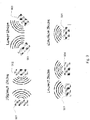
- two sensors 300 and 302 may be placed so that their respective RF pulses are projected in the direction of the opposing sensor.
- sensor 300 may transmit RF pulse 312 in the direction of sensor 302
- sensor 302 may transmit RF pulse 310 in the direction of sensor 300.
- the sensor 300 may receive the reflection of its RF pulse 312, the direct RF pulse 310 of the opposing sensor 302, as well as the opposing sensor's double-reflection RF pulses (not shown).
- the RF pulses received by a sensor may include more than just the desirable RF pulse reflections created by the RF signal that the sensor originally transmitted, resulting in baseband interference when the received RF pulses are demodulated.
- RF waves from other apparatus may also be received by the sensors.
- Such RF waves may come from apparatus located both near and far from the sensors. Due to the nature of RF waves, they may possess the ability to travel through barriers such as walls and other obstacles and geographical topography. Accordingly, embodiments of the present technology may be directed to significantly diminishing the sensors' susceptibility to RF coexistence issues.
- the transmitted, received and resultant RF signals may be represented with the following mathematical formulas:
- the amount of interference generated by an RF signal transmitted from an apparatus or source other than the receiving sensor may be dependent on the received signal strength of the unwanted interfering RF signal.
- the unwanted interfering RF signal's strength may be dependent upon the path the interfering RF signal travels before arriving at the receiving sensor.
- an interfering signal 806 may be reflected off of an object 804 and received by the receiving sensor 800. Accordingly, the power of the interfering RF signal 806 is reduced when it arrives at the receiving sensor 800, compared to the case when the signal arrives directly at the receiving sensor 800.
- an interfering signal 808 may be generated by a second active source 802 and received directly by sensor 800, without incurring any reflections. As no reflection of the interfering signal 808 occurs, the power of the interfering signal 808 is only reduced based on distance travelled. Accordingly, the power of the interfering RF signal is reduced based on distance.
- the interfering signal level from the second unit can be higher than the signal transmitted by the first sensor and reflected back to the first sensor because of the shorter effective path length and the absence of attenuation due to scattering.
- the interfering RF signal When an interfering RF signal is received at a sensor, the interfering RF signal will cause baseband noise under certain conditions: (1) the interfering RF frequency is in-band (i.e. close to 10.525GHz, 10.587GHz, 9.3GHz, 61GHz, 24GHz, 10.45GHz), (2) the interfering RF signal is received during the receive time interval of the sensor, (3) the frequency of the RF signal transmitted by the sensor and the frequency of interfering RF signal have a difference frequency that is a multiple of the pulse repetition frequency of the transmitted frequency signal, and (4) the RF interfering signal has a sufficient amplitude to produce an interfering noise signal.
- the interfering RF frequency is in-band (i.e. close to 10.525GHz, 10.587GHz, 9.3GHz, 61GHz, 24GHz, 10.45GHz)
- the interfering RF signal is received during the receive time interval of the sensor
- RF1 represents the main sensor's RF centre frequency
- RF2 represents the interfering sources RF centre frequency
- IF1 represents the intermediate frequency
- an intermediate frequency (IF) may be considered a frequency to which a carrier frequency is shifted as an intermediate step in transmission or reception) of RF 1
- IF2 represents the intermediate frequency of RF2:
- the present technology contemplates implementation of several solutions.
- the sensors may be synchronized in time to avoid any overlap in RF pulses in time.
- the sensors may be configured to pulse in such a way that the probability of interference is negligible.
- two or more sensors may be placed in one housing facing in different directions (e.g., placed midway along the bed at the headboard or at feet). Examples of each of the implementations are detailed herein.
- a second or subsequent sensor can have such a stable emitted frequency and behaviour, that it becomes a nearly optimal interferer to similar sensors that are nearby (i.e., when considering a multiple non-contact range gated sensor system).
- dithering in both time and/or frequency may be used. Dithering of timing may be used to spread the noise, while frequency dithering may be used to prevent interference. For example, as discussed in more detail herein, in some embodiments ramping of the voltage on a diode coupled to a timing oscillator can change diode capacitance. This leads to a change in the frequency of oscillation of the timing oscillator, resulting in timing dithering, such as by dithering timing pulsed involved in the generated pulsed RF signals. Additionally, by ramping the supply voltage of the DRO (Dielectric Resonant Oscillator), the frequency is changed resulting in frequency dithering (e.g., by ramping voltage 2.5-3.0-2.5V) of the RF signals.
- DRO Dielectric Resonant Oscillator
- Time synchronizing of the RF pulses may be implemented by generating a synchronizing pulse from the first sensor (master) to the second sensor (slave). As such, the second sensor would transmit its RF pulse in the quiet period of the first sensor.
- This solution may have the same noise level as shown in the "baseline noise" setup of Fig. 9 .
- the synchronization of all sensors could be driven by an independent controller in a very similar way to that used by a master sensor to drive one or more slave sensors.
- the sensors could act as peers, e.g., control and communication is distributed among devices in the field, whereby each device communicates directly with the devices around it without having to go through/via a master device.
- the timing of the sensors may include synchronous dithering such as at a 1ms interval, or more or less, so synchronization may not be easily achieved.
- the timing of the sensors may be controlled by a ceramic resonator, with only about 1% frequency accuracy.
- the slave unit should be enabled to detect loss of synchronization and maintain the sensor timing.
- both a clock and dither synchronous signal can be transmitted from the master to slave sensor such as to help address issues of the use of dithering and the asynchronous nature of the operations.
- synchronization should be achieved with sub-micro second timing accuracy to maintain the required RF pulse interleave locking.
- the master and slave sensors should know they are required to transmit or receive the synchronization signal. (i.e., the sensors should automatically synchronize when required or be set at installation to synchronize)
- some versions may include generation of a timing synchronization that includes transmission of both a clock and a dither synchronous signal, and which may be with sub micro second timing accuracy.
- a timing synchronization that includes transmission of both a clock and a dither synchronous signal, and which may be with sub micro second timing accuracy.
- ways of achieving this including detecting the RF pulse signal from the master unit.
- the timing of the slave units are adjusted to assure the slave units do not transmit an RF signal at the timing associated with the pulse signal of the master unit.
- a change of timing architecture may be required as the RF pulse signal may not be at the clock frequency of the oscillator.
- phase-locked loop may be required but may be complicated by the dithering. If timing dithering is not employed then the synchronization requirements above are reduced to that of PRF pulse timing synchronization, which is a lesser requirement. Pulse timing dithering might not be employed and instead enhanced interference noise reduction may be achieved by RF frequency dithering in some cases.
- a separate RF synchronization signal may be sent.
- a separate industrial, scientific, and medical band (ISM) RF signal may be generated to provide the synchronization signals from the master unit to slave units.
- ISM industrial, scientific, and medical band
- the ISM RF signal could potentially be piggy-backed on an existing RF communications channel.
- timing synchronization can be implemented through other wireless communications methods, including RF signals such as Bluetooth, Wi-Fi, ZigBee or other proprietary wireless means.
- RF signals such as Bluetooth, Wi-Fi, ZigBee or other proprietary wireless means.
- timing synchronization can be implemented by photonic means such as through light pulses and specifically through an infra-red signal.
- a master sensor 1201 could send an infra-red signal 1204 to slave sensor 1202.
- the master sensor 1201 may include an infra-red transmitter/receiver and the slave sensor 1202 may include an infra-red transmitter/receiver.
- the master sensor 1201 may transmit timing signals from the infra-red transmitter to the infra-red receiver of the slave sensor 1202.
- complications achieving the required coverage and speed required for timing accuracy may be presented.
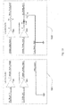
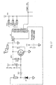
- the master sensor circuit 1301 may include a 4MHz oscillator input U 1 CLK pin 10 buffered by a gate driver/buffer (and supplied as a clock output to the slave. Further, the master sensor circuit may include a 1kHz dither output U1 Q12 pin 1 buffered by gate driver/buffer which is supplied as a reset output to slave. Finally, the master circuit may be connected to ground (0V) and supplied as output to the slave sensor.
- the master clock output is transmitted through a first buffer (on the master circuit) to a wire which is received by a second buffer on the slave circuit.
- the output from the second buffer is presented to the slave clock input.
- the reset output is transmitted through a buffer to a wire which is received by a buffer on the slave circuit.
- the output from the second buffer is presented to the reset pin through a differentiator circuit/high pass filter. Only the leading edge of the reset pulse is passed through to the reset pin.
- the slave circuit may be connected to ground.
- timing dithering is not employed then the synchronization requirements above are reduced to that of PRF pulse timing synchronization which is a lesser requirement.
- the three wiring timing circuit described reduces to that of a two wire timing circuit.
- a two wire circuit can be implemented by transmitting the master reset output and letting the clocks run. This removes the master clock requirement.
- Both the three wire and two wire synchronization circuits described above could be implemented on the circuitry of the sensor or could be located in the connecting wires. The advantage of the latter would be that synchronization circuitry and associated cost would not be included in every unit.
- the oscillator may be implemented with a quartz crystal. Accordingly, less frequent synchronization signals will be necessary as the quartz crystal has a high frequency tolerance and low frequency drift rate. Additionally, only a single synchronization signal is necessary (e.g., clock), as a quartz crystal may be implemented without dithering.
- Another implementation to reduce RF interference between multiple sensors is to synchronize the RF frequencies of the sensors.
- the voltage controlled RF oscillator of the first sensor may synchronize to the RF frequency to the second unit.
- a control circuit within the first sensor can adjust the DRO voltage to a minimum noise voltage by detecting the DRO voltages which result in a high level of interfering noise and by moving to a central control voltage position (i.e. an area of low noise) between these two "high noise level" voltages (e.g., where there is a pattern of constructive, destructive, constructive, destructive etc. interference gives rise to multiple interference maxima.
- RF frequency synchronization between two sensors has been demonstrated to produce the same noise level as if only a single sensor was in use.
- transmitting respective centre frequencies could potentially avoid the use of buffer circuits (unless required), dedicated cables, and/or synchronize radio or infra-red links.
- transmitting a clock signal, clock edge, and/or reset constantly between sensors may require a defined QoS including latency, bandwidth, and other parameters.
- a network such as the Internet or an ad-hoc peer to peer Wi-Fi link such as Wi-Fi Direct using Wi-Fi Protected Setup (WPS) are examples of such a link (e.g., these are examples of links suitable for centre frequencies transmission or for a clock signal transmission).
- WPS Wi-Fi Protected Setup
- sensors may each store copies of lookup tables (or functions or formula to dynamically calculate such frequencies).
- a table or tables may include a set of odd frequencies and a set of even frequencies. The odd and even frequencies may be chosen to sit at nulls in mutual interference.
- the sensors may then be programed to select a frequency to operate at from the odd and even tables.
- the tables may span a region within an allowable spectral mask of a filter associated with a sensor, wherein the region is within the controllable centre frequency range of the sensor.
- the frequencies may be selected from: (0.5 + n) ⁇ PRF;
- n is an integer and PRF is a pulse rate frequency.
- PRF is a pulse rate frequency.
- a first sensor might check if it is operating at or near a frequency in either the even table or the odd table, and make minor adjustments to match one of these close (or closest) frequencies on either table. For example, the first sensor might adjust its frequency to the nearest frequency in the even table. A second sensor may then adjust its frequency to the nearest frequency in the odd table, thereby achieving minimal interference.
- a defined pair may only have to happen once at setup.
- a defined pair configuration may help remove the need for an ongoing wired or wireless transmission between the sensors. Accordingly, complexities introduced by continually updating the frequencies during ongoing operation may be minimized or removed.
- the one-off pairing process for a defined pair could be performed via wired or wireless means.
- NFC near field communications
- accelerometer could be used to enable "tap to pair," whereby close proximity and/or a control signal is used to enable the communication of the table information between sensors.
- the pairing process could be repeated periodically, such as on an occasional or best effort basis (e.g., via a store and forward network) in order to verify that no control parameters have changed.
- a change of location or situation of one or more sensors could cause a system to prompt a user to perform a manual re-pair, or the re-pairing process may be automatically performed in the background.
- each table may be ring-fenced for each respective sensor.
- each sensor may be assigned to a range of possible frequencies on the even table, or to a range of possible frequencies on the odd table.
- the switch may be set to adjust which frequency the sensor will operate at, or to select whether the sensor will operate at frequencies of the even table or the frequencies of the odd table or some portion thereof.
- RF environment it also may be desirable that other metrics of the RF environment be collected by one or more sensor devices of the system.
- other metrics of the RF environment which may be collected could be the spacing or a measure of distance between the sensors and the relative orientation of the sensors.
- a configuration may be programmed such that the sensors cooperate in order to minimise mutual interference. Should the sensors be placed in a position where an elevated level of residual interference is likely, before or after a pairing routine is performed, the sensors may provide a notification to reposition or re-orient one or more of the sensors.
- third party sources of RF signals may interfere with the operation of a sensor by accidentally or actively jamming the pulse sequences.
- Such third party sources operating at a similar centre frequency to a sensor may be considered "foes"; examples could be a sensing technology from another manufacturer or supplier operating at a similar frequency / pulsing strategy, or perhaps a malicious user trying to deliberately disrupt the operation of a medical cardiorespiratory sensor.
- PIR passive infrared sensor
- microwave security detector e.g., where the microwave detector component operates at a similar RF centre frequency
- RADAR high power aviation RADAR
- military, police or traffic management or vehicular RADAR may all produce similar centre frequencies which could interfere with operation of a sensor.
- the sensors may be programmed to deliberately scan a frequency range to determine the presence of interference.
- one or more of the friendly sensors may each modify its centre frequency, in a search mode to attempt to maximise interference.
- the sensors may then reconfigure their centre frequency to minimise interference.
- a frequency range between the maximised and minimum interference frequencies may then be determined by the sensor(s).
- the sensors may then determine if the frequency range is related to, for example, a known frequency range, and if so, the sensors may assume that another sensor of a known type is the source of the interference. Such scanning would preferentially occur during the absence of any motion in the vicinity of the sensors.
- the sensors may initiate communication (e.g., using Manchester coding). For example, one or more of the sensors may adjust their respective centre frequencies around a determined interference maximum until two or more sensors agree upon the maxima.
- a first sensor may move its centre frequency at a predefined rate, with the second (or plurality of other sensors) detecting when an interference maxima is achieved.
- Each sensor could communicate an agreed upon maxima point, and then agree which sensor should move to seek a minima frequency point.
- the sensor which adjusted to the minima would hold at that centre frequency until a correction is needed, for example, to account for temperature drift or other changing factor.
- sensors may be reconfigurable, e.g., have the ability to dynamically adjust centre frequency by, for example, including a processor that controls varying voltage to a voltage controlled oscillator for example, and/or other RF characteristics including pulse timing and radiated power.
- coding may be applied to some RF pulse trains to enable faster communication between "friends" without using other communications channels.
- a temperature variation reference e.g., detection of a certain temperature change, may be used to trigger or initiate polling between the sensors for updating the frequencies of each sensor to avoid interference as a result of recent temperature changes.
- a foe may transmit a RF signal with a centre frequency close or identical to the frequencies being transmitted by the one or more sensors. Accordingly, it is desirable for sensors to be able to operate in the presence of foes which may transmit jamming signals or other malicious RF emissions.
- the continued detection of an RF interference, caused by a foe, by a sensor cooperating with another sensor or sensors may prompt a system to adjust the frequencies within which it is operating. For example, the system may carry out a search across an allowable lookup table of values or other allowable blocks of radio spectrum in order to find a situation such that the unusual external interference is minimised. If the third party source was a sensor using a similar pulsing scheme, it can be seen that moving to a null interference frequency (e.g., moving centre frequency by 125 kHz might be sufficient to minimise interference, and/or by adjusting PRF).
- a null interference frequency e.g., moving centre frequency by 125 kHz might be sufficient to minimise interference, and/or by adjusting PRF.
- a sensor could adjust centre frequency in steps in order to build up a picture of the local RF environment, and carry out an optimization process (e.g., using gradient descent interference avoidance) in order to locate an interference minima over time. In some examples, this may require a large change in centre frequency, such as, for example, a move from 10.587 GHz to 9.3 GHz (or vice versa).
- the system may inform a user. For example, the system may attempt to adjust operation via clocking, transmission of adjusted centre frequencies or centre traversal via a special lookup table. If such adjustments are unsuccessful, the system may inform the user that a readjustment is "Unsuccessful," as residual interference detected is such that it exceeds a predefined acceptable threshold. Optionally, such information can be presented to the user only if the interference is sustained in nature. In certain extreme cases of interference, the sensor's RF radio may be turned off automatically, and an error signal set (e.g., displayed on a screen). As such, the sensor may be unable to process and/or extract physiological signals, and thus unable to detect user's biometric parameters. Further, if detected, the biometric parameters may be inaccurate.
- an error signal set e.g., displayed on a screen
- noise reduction may be achieved without synchronization between two or more sensors.
- the sensors may be configured to minimize RF coexistence issues without synchronizing the frequency or timing of the sensors.
- Another technique for noise reduction may include dithering the pulse timing of each sensor differently or maintaining the pulse timing of each sensor at a constant frequency offset to each other.
- the different timing from a master and slave sensor could reduce the chance of the sensors RF pulses locking in-phase with each other.
- the pulse timing dither between two sensors may also be increased and made pseudo random to reduce noise. Similar to dithering the time of each sensor, the dithering cycle could be extended and made pseudorandom for either, or both, the master and slave sensor.
- a second binary ripple counter and exclusive OR gate, or a microcontroller or processor may be used to create the extended and pseudorandom dithering cycle.
- the synchronous nature of the dithering or pseudo random timing dithering with the PRF (and IF) is significant so that tone artefacts are not produced by the phase sensitive demodulator receiver of the sensor.
- a diode may be coupled with a timing oscillator (e.g., pulse generator 408 of Fig.
- timing dithering may occur.
- DRO dielectric resonant oscillator
- frequency dithering has the advantage of mitigating external RF interference.
- an additional circuit to either modulate the drain voltage of the DRO or dither the supply voltage of the DRO from a voltage controlled regulator may be required. In this regard, by ramping the supply voltage of the DRO, the frequency output by the DRO may be adjusted.
- Frequency dithering may allow for multiple sensors to coexist in a common vicinity. For example, by employing frequency dithering, the center frequency of each sensor is moving such that there is a statistically insignificant chance that interference occurs between the sensors in normal operation. Such a technique may also be utilized by itself or in addition to timing dithering.
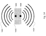
- Another technique for reducing noise between sensors is by positioning the sensors in a single housing unit. As shown in Fig. 14 , two sensors 1406 and 1408 are placed within housing unit 1400. Sensor 1406 is placed 180 degrees away from sensor 1408, and accordingly signals 1402 and 1404 create minimal, if any, interference. Turning back to Fig. 9 , the lowest level of noise between sensors occurs when the sensors are placed at least 90 degrees apart. Accordingly, when placing the sensors within the housing, they should be at an angle of at least 90 degrees from each other. A benefit of this technique is the sensors can be easily synchronized through a direct connection.
- the location of the sensors has a role to play in reducing noise. Placing sensors in close proximity and in a line of sight of each other produces maximum interference noise. This noise can be mitigated by orienting the sensors to increase the effective path length. Locating sensors further apart and at an angle to each other is an effective means of reducing coexistence noise
- the sensors transmit and receive RF signals are circularly polarised (i.e., their RF signal electric and magnetic fields have a preferred transmit and receive direction) then further noise reduction can be achieved by arranging the sensors such that the polarisation of one sensor is orthogonal to that of the other. In this way the reflected movement signal is preferred (suffers no attenuation due to polarisation) while the received interference RF signal is rejected (suffers attenuation due to its orthogonal polarisation).
- Noise reduction may also be obtained by using more than one of the previously described noise reduction architectures and/or techniques.
- S represents Synchronization and “D” represents Dithering.
- D represents Dithering.
- t represents Timing (which includes IF timing and PRF timing)
- f represents the RF centre frequency
- no intervention i.e., noting/nothing is the trivial as-is case.
- Table shows the case of 1 co-existing sensor, but could be extended to (1, 2, ... n) linked sensors.
- synchronization of timing implies the synchronization of a wired or wireless control signal (i.e., a first control signal); if dithering is also employed (simultaneous synchronization of timing and the dithering of timing), then a second control signal is used to facilitate synchronization.
- a wired or wireless control signal i.e., a first control signal
- dithering is also employed (simultaneous synchronization of timing and the dithering of timing)
- a second control signal is used to facilitate synchronization.
- timing synchronization this implies that the PRF timing are locked.
- dithering this implies that IF and PRF are synchronised, but dithered (hence the requirement for the second control signal).
- timing synchronization requires good RF pulse isolation. (RF bleed through of the RF signal during the OFF period of the RF modulation results in poor RF pulse isolation). Therefore, it is desirable to turn off the RF radio transmitter between pulses or other approaches to remove this bleed through.
- timing dither and frequency synchronization [t(D) f(S)] is likely to perform well.
- the combination of timing synchronization and frequency synchronization [t(S) f(S)] is also likely to perform well, especially if there is good isolation, or timing synchronization and timing dither and frequency synchronization [t(S,D) f(S)].
- a centre frequency of a sensor may shift, even under the control of a DRO, as certain operating parameters change.
- a variation in both ambient and internal temperature may cause a sensor's frequency output to shift.
- sensors may experience repeated and significant changes in temperature if a high power light or heat source is in proximity of, or in the same housing as, an RF sensor, and such a source switches on or off over time.
- There may also be a shift in centre frequency when a product with a processor and sensor is first turned on, and the enclosure reaches the expected operating temperature of the system (which may be above ambient temperature).
- embodiments may include design parameters to assist the sensor in outputting a certain frequency, regardless of any temperature variations.
- any temperature or related change in centre frequency may automatically be corrected.
- the sensors may be adjusted by the techniques previously described regarding QoS.
- optimal spacing may be maintained.
- the sensors may transmit the values read from the sensors over a network, which allows the adjustment of one or more sensors in such a way that defined frequency spacing is achieved and retained. As such, interference between sensors may be minimized.
- Such corrections may be made based on a change or delta in a centre frequency of a sensor above a defined threshold.
- each sensor may be able to dynamically detect their current centre frequency (e.g., as drifting due to a change in temperature or other parameter), and continually or on a periodic basis adjust its frequency in order that it matches an agreed lookup table centre frequency. Such adjustments may thereby minimising interference between the sensors, while assuring the sensors remain within a defined spectral mask.
- their current centre frequency e.g., as drifting due to a change in temperature or other parameter
- RF sensor variation and processor control offsets may also be used to estimate the temperature such that an RF sensor alone could be used to estimate temperature to a certain resolution.
- the temperatures may allow for sensor start-up effects, and further, the resolution may enable temperature sensing where no separate temperature sensor is provisioned. Accordingly, no prior knowledge of a temperature coefficient of the oscillator may be necessary.
- the amount of times a sensor may provide its actual centre frequency to nearby sensors may be reduced by reading and accurately setting the centre frequency at the time of manufacture.
- NTP network time protocol
- UDP User Datagram Protocol
- crystals may have a known clock rate and accuracy.
- a crystal may have an accuracy of 20 parts per million, and an associated variation with temperature.
- a timing calibration can be performed on the 4 MHz clock. In this regard, once the current time is available, it is possible to send to the other devices.
- the clock rate in this example a 4 MHz clock
- a frequency rate for example 10.525 GHz.
- a harmonic of the 4 MHz clock signal appears on the received signal. Therefore, based on the output, there is a frequency that is: n ⁇ actual frequency
- a clock synchronization signal may be calculated. For example, a reference frequency may be found from an internet source. Based on passage of time using the NTP, a clock synchronization signal may be calculated. This synchronization signal may then be sent to the other sensors.
- Sensors may be switched to a low power search mode (or even a sleep or off mode) if no motion is detected for a predetermined amount of time.
- a sensor might be integrated into body worn devices, such as pendants, chest bands, bracelets, watches, hats, and other such devices. Additionally, sensors may be directly into existing electronics devices such as, smart watches, smartphones, internet of things (IoT) devices, etc.
- IoT internet of things
- sensors may be programmed to switch to a low power search mode if the device which the sensor is integrated is not being used, such as if no motion is detected.
- a sensor integrated into a pendant may be placed onto a dresser. Since the user is not wearing the pendant, the sensor may detect no motion. Accordingly, the range of the sensor may be adjusted by reducing the output power, frequency, and/or duration of pulses to reduce the overall power consumption. Further, the adjustments may be programmed to be within allowable ranges. While sensors integrated into devices are described, standalone sensors may also be programmed to switch to a lower power search mode if the sensor fails to detect motion. Therefore, a low power condition can act a further aid to coexistence, by reducing the RF emitted power of one or more sensors.
- Processing of signals may be performed by a processor on a sensor printed circuit board assembly (PCBA).
- PCBA sensor printed circuit board assembly
- Such a PCBA may also allow communication over an analog and/or digital link with a remote processor, such as a microprocessor on a main board.
- signals may be digitized and transmitted over a wireless or wired connection. Digitisation may be performed at a high resolution and/or sampling rate, and the sensor signals themselves (e.g., in-phase (I) and quadrature (Q) streams, or a stream prior to or not requiring such separation of I and Q), may be transmitted to a single or multiple processors. Further, each channel of transmitted information may also contain information about current or recent centre frequency, relative changes in centre frequency, lookup table location in use, etc.
- I in-phase
- Q quadrature
- the number of components to implement a multi-sensor system may be reduced by minimising component count on one or more sensors.
- the system may utilise existing data links and/or data processing power available in a wider system implementation in order to achieve the desired motion and physiological sensing.
- sensors may transmit their respective signals to a remotely located, separately housed processor, capable of processing multiple sensor signals at once.
- digitised sensor signals could be transcoded to audio frequencies such that existing audio processing accelerators and routines might be utilised in order to detect specific motion patterns.
- detection apparatus 100 detection apparatus 102 sensor 300 sensor 302 RF pulse 310 RF pulse 312 sensor 402 oscillator 404 pulse generator 408 periodic sinusoidal amplitude envelope 600 signal 602 signal 700 signal 702 resultant receiver RF signal 704 sensor 800 second active source 802 object 804 rf signal 806 signal 808 master sensor 1201 slave sensor 1202 red signal 1204 master sensor circuit 1301 slave sensor circuit 1302 housing unit 1400 signal 1402 signal 1404 sensor 1406 sensor 1408
Landscapes
- Health & Medical Sciences (AREA)
- Engineering & Computer Science (AREA)
- Life Sciences & Earth Sciences (AREA)
- Radar, Positioning & Navigation (AREA)
- Remote Sensing (AREA)
- Physics & Mathematics (AREA)
- Computer Networks & Wireless Communication (AREA)
- General Health & Medical Sciences (AREA)
- Medical Informatics (AREA)
- Veterinary Medicine (AREA)
- Biophysics (AREA)
- Pathology (AREA)
- Biomedical Technology (AREA)
- Heart & Thoracic Surgery (AREA)
- Public Health (AREA)
- Molecular Biology (AREA)
- Surgery (AREA)
- Animal Behavior & Ethology (AREA)
- General Physics & Mathematics (AREA)
- Physiology (AREA)
- Cardiology (AREA)
- Signal Processing (AREA)
- Dentistry (AREA)
- Oral & Maxillofacial Surgery (AREA)
- Psychiatry (AREA)
- Artificial Intelligence (AREA)
- Computer Vision & Pattern Recognition (AREA)
- Nuclear Medicine, Radiotherapy & Molecular Imaging (AREA)
- Electromagnetism (AREA)
- Radiology & Medical Imaging (AREA)
- Pulmonology (AREA)
- Radar Systems Or Details Thereof (AREA)
- Measurement Of The Respiration, Hearing Ability, Form, And Blood Characteristics Of Living Organisms (AREA)
- Measuring Pulse, Heart Rate, Blood Pressure Or Blood Flow (AREA)
- Mobile Radio Communication Systems (AREA)
- Measuring And Recording Apparatus For Diagnosis (AREA)
Claims (24)
- Funkfrequenzsensor (100, 102, 300, 302) für physiologische Bewegungen, der zum Betrieb in einer Multisensor-Konfiguration konfiguriert ist, wobei der Funkfrequenzsensor für Bewegungen Folgendes aufweist:einen Funkfrequenzsender, der zum Emittieren von gepulsten Funkfrequenzsignalen (310, 312) konfiguriert ist; undeinen Empfänger, der zum Empfangen von reflektierten Signalen der emittierten gepulsten Funkfrequenzsignale (310, 312) konfiguriert ist, um Bewegung einer reflektierenden Fläche zu erkennen;wobei Sender und Empfänger zum Erkennen von mindestens einer physiologischen Eigenschaft eines Benutzers konfiguriert sind;wobei der Sender für den Betrieb mit einem weiteren Funkfrequenzsensor für physiologische Bewegungen in einer Nähe des Funkfrequenzsensors für physiologische Bewegungen konfiguriert ist, um Interferenz zwischen von den Funkfrequenzsensoren für physiologische Bewegungen emittierten Impulsen durch Dithern der Taktung der Impulserzeugung mittels einer Dither-Schaltung mit synchroner Rampe abzuschwächen.
- Funkfrequenzsensor für physiologische Bewegungen nach Anspruch 1, wobei der Sender zum synchronisierten Senden der gepulsten Funkfrequenzsignale mit einem weiteren Funkfrequenzsensor für physiologische Bewegungen in einer Nähe des Funkfrequenzsensors für physiologische Bewegungen konfiguriert ist, um Interferenz zwischen von den Funkfrequenzsensoren für physiologische Bewegungen ausgesendeten Impulsen abzuschwächen,
wobei der Sender zeitlich synchronisiert ist, um emittierte gepulste Funkfrequenzsignale mit emittierten gepulsten Funkfrequenzsignalen des weiteren Funkfrequenzsensors für physiologische Bewegungen zu verschachteln,
und wobei vorzugsweise die Synchronisation zwischen den Funkfrequenzsensoren für physiologische Bewegungen das Senden eines Taktsignals umfasst. - Funkfrequenzsensor für physiologische Bewegungen nach Anspruch 2, wobei die Synchronisation zwischen den Funkfrequenzsensoren für physiologische Bewegungen das Senden eines synchronisierten Dither-Signals umfasst,
und wobei vorzugsweise (a) der Funkfrequenzsensor für physiologische Bewegungen eine Taktung von einem emittierten gepulsten Funkfrequenzsignal erkennt oder (b) der Funkfrequenzsensor für physiologische Bewegungen ein Synchronisationssignal erkennt, das unabhängig von den emittierten gepulsten Funkfrequenzsignalen ist. - Funkfrequenzsensor für physiologische Bewegungen nach einem der Ansprüche 2 bis 3, wobei (a) der Funkfrequenzsensor für physiologische Bewegungen ferner einen Sender für Infrarotsignale aufweist, der zur Taktung der emittierten gepulsten Funkfrequenzsignale ausgelegt ist, oder (b) der Funkfrequenzsensor für physiologische Bewegungen eine Schnittstelle für eine Kabelverbindung mit dem weiteren Funkfrequenzsensor für physiologische Bewegungen aufweist, wobei die Kabelverbindung zur Taktung der emittierten gepulsten Funkfrequenzsignale konfiguriert ist.
- Funkfrequenzsensor für physiologische Bewegungen nach Anspruch 2, wobei (a) der Sender in Bezug auf die Frequenz mit einem Sender des weiteren Funkfrequenzsensors für physiologische Bewegungen synchronisiert ist, um Interferenz zu reduzieren, oder (b) der Sender einen veränderlichen Oszillator aufweist, der zur Frequenzeinstellung als Reaktion auf erkannte Interferenzgeräusche konfiguriert ist.
- Funkfrequenzsensor für physiologische Bewegungen nach einem der Ansprüche 2 bis 5, wobei (a) der Sender für Frequenz-Dithering konfiguriert ist und/oder (b) der Sender für Takt-Dithering konfiguriert ist.
- Funkfrequenzsensor für physiologische Bewegungen nach Anspruch 6, wobei (a) Frequenz-Dithering durch rampenförmiges Anheben eines Spannungspegels zu mindestens einem Oszillator des Sensors erfolgt, um Frequenz-Dithering zu erzeugen, oder (b) Takt-Dithering durch rampenförmiges Anheben eines Spannungspegels zu einer Diode, die mit mindestens einem Oszillator des Sensors gekoppelt ist, erfolgt, um Takt-Dithering zu erzeugen.
- Funkfrequenzsensorvorrichtung für physiologische Bewegungen, die Folgendes aufweist:mindestens zwei Funkfrequenzsensoren, wobei jeder Sensor den Funkfrequenzsensor für physiologische Bewegungen nach einem der Ansprüche 1 bis 7 aufweist, wobei die Vorrichtung ein Gehäuse zum Halten der Sensoren in einer Konfiguration zum Emittieren der Funkfrequenzsignale in verschiedene Richtungen aufweist, um Interferenz zwischen von den Funkfrequenzsensoren emittierten Impulsen abzuschwächen,und wobei vorzugsweise (a) die Sensoren zum Leiten der emittierten Impulse in einem relativen Winkel von etwa 90 Grad bis 270 Grad angeordnet sind oder (b) die Sensoren zum Leiten der emittierten Impulse in einem relativen Winkel von mindestens etwa 180 Grad angeordnet sind.
- System zum Senden von Funkfrequenzen zum Erkennen von physiologischen Eigenschaften, das mindestens zwei Funkfrequenzsensoren umfasst, von denen jeder den Funkfrequenzsensor für physiologische Bewegungen (100, 102, 300, 302) nach einem der Ansprüche 1 bis 7 aufweist, wobei die mindestens zwei Funkfrequenzsensoren für Bewegungen Folgendes aufweisen:(a) einen Master-Funkfrequenzsensor für physiologische Bewegungen und(b) einen Slave-Funkfrequenzsensor für physiologische Bewegungen;und wobei:der Master-Funkfrequenzsensor für physiologische Bewegungen zum Senden eines ersten Funkfrequenzsignals (RF-Signals) konfiguriert ist undder Slave-Funkfrequenzsensor für physiologische Bewegungen zum Senden eines zweiten RF-Signals konfiguriert ist, wobei Interferenz zwischen dem ersten Funkfrequenzsignal (RF-Signal) und dem zweiten RF-Signal minimiert wirdund wobei der Slave-Funkfrequenzsensor für physiologische Bewegungen so zum Senden des zweiten RF-Signals konfiguriert ist, dass das zweite RF-Signal minimale Interferenz mit dem ersten Funkfrequenzsignal (RF-Signal) erzeugt; undwobei (a) der Master-Funkfrequenzsensor für physiologische Bewegungen und der Slave-Funkfrequenzsensor für physiologische Bewegungen in einem einzigen Gehäuse angeordnet sind oder (b) wobei der Master-Funkfrequenzsensor für physiologische Bewegungen und der Slave-Funkfrequenzsensor für physiologische Bewegungen in einem Winkel von 90 Grad in einem einzigen Gehäuse angeordnet sind.
- System nach Anspruch 9, wobei ein RF-Sender zum Senden mindestens eines RF-Synchronisationsimpulssignals und der Slave-Funkfrequenzsensor für physiologische Bewegungen ferner zum Empfangen des RF-Synchronisationsimpulssignals konfiguriert ist, und wobei vorzugsweise der Slave-Funkfrequenzsensor für physiologische Bewegungen ferner zum Erkennen des empfangenen RF-Synchronisationsimpulssignals auf einer Zwischenfrequenz konfiguriert ist.
- System nach Anspruch 10, wobei der Master-Funkfrequenzsensor für physiologische Bewegungen ferner zum Senden des mindestens einen RF-Synchronisationsimpulssignals auf einem separaten industriellen, wissenschaftlichen und/oder medizinischen Übertragungsband (ISM) konfiguriert ist.
- System nach Anspruch 9, wobei:(a) der Master-Funkfrequenzsensor für physiologische Bewegungen und der Slave-Funkfrequenzsensor für physiologische Bewegungen ferner eine Master-Slave-Oszillatorschaltung aufweisen,(b) der Master-Funkfrequenzsensor für physiologische Bewegungen und der Slave-Funkfrequenzsensor für physiologische Bewegungen ferner eine Master-Slave-Oszillatorschaltung aufweisen, wobei die Master-Slave-Oszillatorschaltung ferner eine mehradrige Kabelverbindung aufweist, die zum Senden von Taktungs- und Dithering-Synchronisationsinformationen vom Master-Funkfrequenzsensor für physiologische Bewegungen zum Slave-Funkfrequenzsensor für physiologische Bewegungen konfiguriert ist, oder(c) der Master-Funkfrequenzsensor für physiologische Bewegungen und/oder der Slave-Funkfrequenzsensor für physiologische Bewegungen mindestens eine Resonator-Oszillatorschaltung umfasst, wobei vorzugsweise der Slave-Funkfrequenzsensor für physiologische Bewegungen die mindestens eine Resonator-Oszillatorschaltung sowie einen spannungsgeregelten RF-Oszillator umfasst und der spannungsgeregelte RF-Oszillator zum Synchronisieren seiner RF-Signalfrequenz mit der des Master-Funkfrequenzsensors für physiologische Bewegungen konfiguriert ist und wobei der spannungsgeregelte RF-Oszillator bevorzugt zum Synchronisieren der RF-Frequenz mit dem Master-Funkfrequenzsensor für physiologische Bewegungen konfiguriert ist, indem er eine hohe Spannung erkennt, die zu einem hohen Interferenzgeräuschpegel führt, eine niedrige Spangelten RF-Oszillator in eine zentrale Steuerspannungsposition zwischen der hohen und niedrigen Spannung bewegt.
- System nach einem der Ansprüche 8 bis 11, wobei der Master-Funkfrequenzsensor für physiologische Bewegungen einen ersten binären Asynchronzähler mit Exklusiv-ODER-Gatter umfasst; und
der Slave-Funkfrequenzsensor für physiologische Bewegungen einen zweiten binären Asynchronzähler mit Exklusiv-ODER-Gatter umfasst;
wobei der erste und zweite binäre Asynchronzähler und die Exklusiv-ODER-Gatter zum Erzeugen eines pseudozufälligen Dithering-Takts konfiguriert sind. - System nach einem der Ansprüche 8 bis 12, wobei:(a) der Master-Funkfrequenzsensor für physiologische Bewegungen einen ersten dielektrischen Resonanzoszillator umfasst, wobei der erste dielektrische Resonanzoszillator durch eine erste Spannung moduliert wird, und
der Slave-Funkfrequenzsensor für physiologische Bewegungen einen zweiten dielektrischen Resonanzoszillator umfasst, wobei der zweite dielektrische Resonanzoszillator durch eine zweite Spannung moduliert wird, oder(b) das erste Funkfrequenzsignal (RF-Signal) und das zweite RF-Signal auf unterschiedlichen Frequenzen liegen. - System zum Senden von Funkfrequenzen zum Erkennen von physiologischen Eigenschaften, das einen ersten Funkfrequenzsensor für physiologische Bewegungen nach einem der Ansprüche 1 bis 7 aufweist, wobei das System ferner Folgendes aufweist:einen zweiten Funkfrequenzsensor für physiologische Bewegungen;wobei der erste Funkfrequenzsensor für physiologische Bewegungen zum Senden eines ersten Funkfrequenzsignals (RF-Signals) konfiguriert ist; undder zweite Funkfrequenzsensor für physiologische Bewegungen zum Senden eines zweiten RF-Signals konfiguriert ist, wobei das System zum Minimieren von Interferenz zwischen den RF-Signalen von beiden Sensoren eingerichtet ist,und wobei vorzugsweise (a) der erste Funkfrequenzsensor für physiologische Bewegungen zum Empfangen einer Angabe der vom zweiten Funkfrequenzsensor für physiologische Bewegungen gesendeten Frequenz konfiguriert ist und der zweite Funkfrequenzsensor für physiologische Bewegungen zum Empfangen einer Angabe der vom ersten Funkfrequenzsensor für physiologische Bewegungen gesendete Frquenz konfiguriert ist und (b) der erste Funkfrequenzsensor für physiologische Bewegungen zum Einstellen der Frequenz des ersten Funkfrequenzsignals (RF-Signals) als Reaktion auf die empfangene Angabe der vom zweiten Funkfrequenzsensor für physiologische Bewegungen gesendeten Frequenz konfiguriert ist.
- System nach Anspruch 15, wobei der erste Funkfrequenzsensor für physiologische Bewegungen und der zweite Funkfrequenzsensor für physiologische Bewegungen jeweils zum Zugreifen auf eine Zuordnungstabelle konfiguriert ist, die wählbare Frequenzen umfasst, auf denen die Sensoren arbeiten können,
und wobei bevorzugt der erste Funkfrequenzsensor für physiologische Bewegungen zum Wählen einer Frequenz aus einer ersten Zuordnungstabelle und der zweite Funkfrequenzsensor für physiologische Bewegungen zum Wählen einer Frequenz aus einer zweiten Zuordnungstabelle konfiguriert ist,
und wobei bevorzugt die erste Zuordnungstabelle ungerade Frequenzen und die zweite Zuordnungstabelle gerade Frequenzen umfasst. - System nach Anspruch 15, wobei (a) der erste Funkfrequenzsensor für physiologische Bewegungen und der zweite Funkfrequenzsensor für physiologische Bewegungen zum Einstellen ihrer jeweiligen Frequenz mit einem Network Time Protocol (NTP) konfiguriert sind, (b) der erste Funkfrequenzsensor für physiologische Bewegungen und der zweite Funkfrequenzsensor für physiologische Bewegungen zum Einstellen ihrer jeweiligen Sendefrequenz als Reaktion auf das Erkennen von Interferenz konfiguriert sind oder (c)
der erste Funkfrequenzsensor für physiologische Bewegungen und der zweite Funkfrequenzsensor für physiologische Bewegungen zum Einstellen ihrer jeweiligen Sendefrequenz auf der Grundlage von vorherbestimmten Temperaturkoeffizienten konfiguriert sind. - System nach einem der Ansprüche 15 bis 17, wobei der erste Funkfrequenzsensor für physiologische Bewegungen und der zweite Funkfrequenzsensor für physiologische Bewegungen zum Prüfen oder Einstellen der Frequenz konfiguriert sind, mit der sie RF-Signale als Reaktion auf Eingaben von einem geographischen Standort senden,
und wobei vorzugsweise der erste Funkfrequenzsensor für physiologische Bewegungen und/oder der zweite Funkfrequenzsensor für physiologische Bewegungen zum Betrieb in einem Energiesparmodus konfiguriert ist, wenn keine Bewegung vorliegt. - System nach Anspruch 15, wobei der erste Funkfrequenzsensor für physiologische Bewegungen und/oder der zweite Funkfrequenzsensor für physiologische Bewegungen für Folgendes konfiguriert ist:Senden periodischer Mittenfrequenzwerte, die aus dem jeweiligen Sensor über ein Netzwerk ausgelesen wurden; undEinstellen der Frequenz, mit der die einzelnen Sensoren senden, um Interferenz zwischen dem ersten und zweiten Sensor zu minimieren.
- System nach einem der Ansprüche 15 und 16, wobei:(a) der erste Funkfrequenzsensor für physiologische Bewegungen und/oder der zweite Funkfrequenzsensor für physiologische Bewegungen für Folgendes konfiguriert ist:Dynamisches Erkennen seiner aktuellen Mittenfrequenz undPeriodisches Einstellen einer solchen Frequenz, damit sie einer vereinbarten Mittenfrequenz aus der Zuordnungstabelle entspricht und Interferenz zwischen dem ersten Funkfrequenzsensor für physiologische Bewegungen und dem zweiten Funkfrequenzsensor für physiologische Bewegungen minimiert wird, aber eine definierte Spektralmaske beibehalten wird,(b) wobei der erste Funkfrequenzsensor für physiologische Bewegungen und der zweite Funkfrequenzsensor für physiologische Bewegungen für Folgendes konfiguriert ist:Dynamisches Abtasten eines Frequenzbereichs, um die minimale und maximale Interferenz zu erkennen, undEinstellen einer Mittenfrequenz mindestens eines der Sensoren auf eine Frequenz, die mit der minimalen Interferenz verbunden ist, und wobei die Sensoren bevorzugt über eine Frequenz von maximaler Interferenz kommunizieren oder(c) der erste Funkfrequenzsensor für physiologische Bewegungen und/oder der zweite Funkfrequenzsensor für physiologische Bewegungen für Folgendes konfiguriert ist:Erkennen einer Temperaturänderung undInitiieren von Abfragen zwischen den Sensoren auf der Grundlage der erkannten Temperaturänderung, um die Mittenfrequenz mindestens eines der Sensoren einzustellen.
- System nach Anspruch 15 (a), wobei das System zum Minimieren der Interferenz zwischen den RF-Signalen beider Sensoren durch Frequenz-Dithering mindestens eines die RF-Signale generierenden Oszillators der Sensoren eingerichtet ist und wobei ein Spannungspegel mindestens eines des mindestens einen Oszillators zum Erzeugen von Frequenz-Dithering rampenförmig angehoben wird, und/oder (b) wobei das System zum Minimieren der Interferenz zwischen den RF-Signalen beider Sensoren durch Takt-Dithering der Impulse der RF-Signale beider Sensoren eingerichtet ist und wobei ein Spannungspegel zu einer Diode, die mit mindestens einem des mindestens einen Oszillators gekoppelt ist, rampenförmig angehoben wird, um Takt-Dithering bei mindestens einem der Sensoren umzusetzen.
- Funkfrequenzsensor für physiologische Bewegungen nach einem der Ansprüche 1 bis 14, wobei (a) der Funkfrequenzsensor für physiologische Bewegungen ein Funkfrequenzsensor mit pulsierender kontinuierlicher Schwingung ist, (b) physiologisch charakteristische Bewegung durch Modulieren der empfangenen reflektierten Funkfrequenzsignale mit den emittierten Funkfrequenzsignalen erzeugt wird oder (c) der Funkfrequenzsensor für physiologische Bewegungen zum Entfernungssteuern der Funkfrequenzsignale konfiguriert ist,
und wobei vorzugsweise die physiologischen Eigenschaften eine Atmungstätigkeit und/oder einer Herztätigkeit und/oder Extremitätenbewegung umfassen,
und wobei vorzugsweise der Funkfrequenzsensor für physiologische Bewegungen zum Bestimmen einer Phasendifferenz zwischen den emittierten Funkfrequenzsignalen und den empfangenen reflektierten Funkfrequenzsignalen konfiguriert ist, um Atmungs- und/oder Herztätigkeit des Benutzers zu erfassen
und wobei vorzugsweise der Funkfrequenzsensor für physiologische Bewegungen zum Koppeln an eine Atembehandlungsvorrichtung konfiguriert ist, die eine automatische Behandlungsreaktion auf der Grundlage einer Analyse der vom Funkfrequenzsensor für physiologische Bewegungen erkannten physiologischen Eigenschaften bereitstellt,
und wobei vorzugsweise der Funkfrequenzsensor für physiologische Bewegungen zum Informieren eines Benutzers über erkannte Interferenz konfiguriert ist, wenn diese einen vordefinierten Grenzwert überschreitet. - Funkfrequenzsensorvorrichtung für physiologische Bewegungen nach Anspruch 8, wobei:(a) jeder der mindestens zwei Funkfrequenzsensoren ein Funkfrequenzsensor mit pulsierender kontinuierlicher Schwingung ist;(b) die physiologische Bewegung durch Modulieren der empfangenen reflektierten Funkfrequenzsignale mit den emittierten Funkfrequenzsignalen erkannt wird;(c) jeder der mindestens zwei Funkfrequenzsensoren zum Entfernungssteuern der Funkfrequenzsignale konfiguriert ist;(d) die physiologischen Bewegungen des Benutzers eine Atmungstätigkeit und/oder einer Herztätigkeit und/oder Extremitätenbewegung umfassen;(e) jeder der mindestens zwei Funkfrequenzsensoren zum Bestimmen einer Phasendifferenz zwischen den emittierten Funkfrequenzsignalen und den empfangenen reflektierten Funkfrequenzsignalen konfiguriert ist, um Atmungs- und/oder Herztätigkeit des Benutzers zu erfassen;(f) mindestens einer der mindestens zwei Funkfrequenzsensoren zum Koppeln an eine Atembehandlungsvorrichtung konfiguriert ist, die eine automatische Behandlungsreaktion auf der Grundlage einer Analyse der vom mindestens einem der mindestens zwei Funkfrequenzsensoren erkannten physiologischen Eigenschaften bereitstellt; und/oder(g) mindestens einer der mindestens zwei Funkfrequenzsensoren zum Informieren eines Benutzers über erkannte Interferenz konfiguriert ist, wenn diese einen vordefinierten Grenzwert überschreitet.
- System nach einem der Ansprüche 9 bis 21, wobei:(a) beide Sensoren für physiologische Bewegungen Funkfrequenzsensoren mit pulsierender kontinuierlicher Schwingung sind;(b) beide Sensoren für physiologische Bewegungen zum Erkennen von physiologischen Eigenschaften durch Modulieren der empfangenen reflektierten Funkfrequenzsensorsignale mit emittierten Funkfrequenzsensorsignalen konfiguriert sind;(c) beide Sensoren für physiologische Bewegungen zum Entfernungssteuern von Funkfrequenzsensorsignalen konfiguriert sind; und/oder(d) beide Sensoren für physiologische Bewegungen eine Atemtätigkeit und/oder Herztätigkeit und/oder Extremitätenbewegung erkennen.
Priority Applications (1)
| Application Number | Priority Date | Filing Date | Title |
|---|---|---|---|
| EP20189558.8A EP3842822A3 (de) | 2015-04-20 | 2016-04-20 | Funkfrequenzdetektion mit mehreren sensoren |
Applications Claiming Priority (3)
| Application Number | Priority Date | Filing Date | Title |
|---|---|---|---|
| US201562149916P | 2015-04-20 | 2015-04-20 | |
| US201562207670P | 2015-08-20 | 2015-08-20 | |
| PCT/EP2016/058791 WO2016170007A1 (en) | 2015-04-20 | 2016-04-20 | Multi sensor radio frequency detection |
Related Child Applications (1)
| Application Number | Title | Priority Date | Filing Date |
|---|---|---|---|
| EP20189558.8A Division EP3842822A3 (de) | 2015-04-20 | 2016-04-20 | Funkfrequenzdetektion mit mehreren sensoren |
Publications (2)
| Publication Number | Publication Date |
|---|---|
| EP3286576A1 EP3286576A1 (de) | 2018-02-28 |
| EP3286576B1 true EP3286576B1 (de) | 2020-08-12 |
Family
ID=55967210
Family Applications (2)
| Application Number | Title | Priority Date | Filing Date |
|---|---|---|---|
| EP20189558.8A Pending EP3842822A3 (de) | 2015-04-20 | 2016-04-20 | Funkfrequenzdetektion mit mehreren sensoren |
| EP16722062.3A Active EP3286576B1 (de) | 2015-04-20 | 2016-04-20 | Funkfrequenzdetektion mit mehreren sensoren |
Family Applications Before (1)
| Application Number | Title | Priority Date | Filing Date |
|---|---|---|---|
| EP20189558.8A Pending EP3842822A3 (de) | 2015-04-20 | 2016-04-20 | Funkfrequenzdetektion mit mehreren sensoren |
Country Status (6)
| Country | Link |
|---|---|
| US (4) | US10670700B2 (de) |
| EP (2) | EP3842822A3 (de) |
| JP (3) | JP6781167B2 (de) |
| CN (2) | CN107438774B (de) |
| AU (1) | AU2016251231A1 (de) |
| WO (1) | WO2016170007A1 (de) |
Families Citing this family (52)
| Publication number | Priority date | Publication date | Assignee | Title |
|---|---|---|---|---|
| JP2015535993A (ja) * | 2012-09-25 | 2015-12-17 | スクート ネットワークス, インコーポレイテッドScoot Networks, Inc. | 車両アクセス調節システムおよび方法 |
| US10264996B2 (en) * | 2015-10-19 | 2019-04-23 | Sayfe Kiaei | Method and apparatus for wirelessly monitoring repetitive bodily movements |
| WO2018145042A1 (en) * | 2017-02-03 | 2018-08-09 | University Of Notre Dame Du Lac | Heart and lung monitoring with coherent signal dispersion |
| CN109416537B (zh) * | 2016-04-18 | 2023-02-28 | 荣布斯系统集团公司 | 使用两个频带与无人驾驶飞行器通信的系统 |
| US10305520B2 (en) * | 2016-05-27 | 2019-05-28 | Apple Inc. | Removing RF interference through scan rate locking |
| US11241167B2 (en) * | 2016-08-17 | 2022-02-08 | The Regents Of The University Of Colorado, A Body Corporate | Apparatus and methods for continuous and fine-grained breathing volume monitoring |
| US10379201B2 (en) * | 2016-10-26 | 2019-08-13 | GM Global Technology Operations LLC | Radar interference mitigation and collaborative operation |
| US10447068B2 (en) * | 2017-04-03 | 2019-10-15 | Nxp B.V. | Power management circuit |
| EP3388801B1 (de) * | 2017-04-11 | 2020-06-10 | NXP USA, Inc. | Temperatursensorsystem, radarvorrichtung und verfahren dafür |
| CN110944878B (zh) * | 2017-08-02 | 2024-04-30 | 雷德本德有限公司 | 车辆乘员的生命体征的非接触式检测与监视系统 |
| TWI642406B (zh) * | 2017-12-12 | 2018-12-01 | Sil Radar Technology Inc. | 非接觸式自我注入鎖定感測器 |
| US10572048B2 (en) * | 2017-12-21 | 2020-02-25 | Synaptics Incorporated | Method and system for measuring a phase baseline estimate of an input device |
| DE102018201302A1 (de) * | 2018-01-29 | 2019-08-01 | Robert Bosch Gmbh | Verfahren zum Betreiben eines Radarsensorsystems in einem Kraftfahrzeug |
| CN110185545B (zh) * | 2018-02-23 | 2022-01-21 | 大陆汽车电子(连云港)有限公司 | 凸轮轴传感器最小电平宽度设置方法及发动机电控系统 |
| US10687406B2 (en) * | 2018-03-05 | 2020-06-16 | James Andrew Nimmer | Lighting element with integrated wireless communication, control, and motion sensing capability |
| US11468503B2 (en) | 2018-04-16 | 2022-10-11 | Bird Rides, Inc. | On-demand rental of electric vehicles |
| US10772511B2 (en) * | 2018-05-16 | 2020-09-15 | Qualcomm Incorporated | Motion sensor using cross coupling |
| TWI675218B (zh) * | 2018-06-07 | 2019-10-21 | 國立中山大學 | 可抵抗雜波之生理徵象感測器 |
| CN108924355A (zh) * | 2018-06-29 | 2018-11-30 | 努比亚技术有限公司 | 信号频率调整方法、移动终端及计算机可读存储介质 |
| EP3591431B1 (de) * | 2018-07-02 | 2021-05-05 | NXP USA, Inc. | Kommunikationseinheit und verfahren zur taktverteilung und synchronisation |
| US11656321B2 (en) * | 2018-07-23 | 2023-05-23 | Richwave Technology Corp. | Method of microwave motion detection with adaptive frequency control and related devices |
| JP7331085B2 (ja) * | 2018-08-14 | 2023-08-22 | シグニファイ ホールディング ビー ヴィ | マイクロ波センサデバイス、センシング方法、及びセンサデバイスを用いた照明システム |
| WO2020038783A1 (en) * | 2018-08-24 | 2020-02-27 | Signify Holding B.V. | Transmitting sensor signal in dependence on device orientation |
| US11057862B2 (en) | 2018-08-26 | 2021-07-06 | Celeno Communications (Israel) Ltd. | Wi-Fi radar detection using synchronized wireless access point |
| CN110088643B (zh) * | 2018-08-31 | 2021-12-07 | 深圳迈睿智能科技有限公司 | 人体存在探测器及其人体存在探测方法 |
| JP7032556B2 (ja) * | 2018-09-20 | 2022-03-08 | 京セラ株式会社 | 電子機器、電子機器の制御方法、及び電子機器の制御プログラム |
| EP3855213A4 (de) * | 2018-09-20 | 2022-06-15 | Kyocera Corporation | Elektronische vorrichtung, steuerungsverfahren für eine elektronische vorrichtung und steuerungsprogramm für eine elektronische vorrichtung |
| CN109541551A (zh) * | 2018-12-21 | 2019-03-29 | 深圳迈睿智能科技有限公司 | 多波束同频微波探测天线及其制造方法和检测方法 |
| US11105912B2 (en) | 2018-12-31 | 2021-08-31 | Celeno Communications (Israel) Ltd. | Coherent Wi-Fi radar using wireless access point |
| US11102750B2 (en) | 2019-01-01 | 2021-08-24 | Celeno Communications (Israel) Ltd. | Positioning system based on distributed transmission and reception of Wi-Fi signals |
| CN109632146B (zh) * | 2019-01-30 | 2021-01-05 | 浙江帕博电力科技有限公司 | 电力设备温度监测系统和无线温度传感器 |
| CN111657885A (zh) * | 2019-03-05 | 2020-09-15 | 纬创资通股份有限公司 | 生理信息检测系统与方法 |
| US11362750B2 (en) * | 2019-03-11 | 2022-06-14 | Marvell Asia Pte Ltd | Synchronization of automotive sensors using communication-link TDM timing |
| CN110045358B (zh) * | 2019-03-22 | 2022-06-21 | 深圳迈睿智能科技有限公司 | 基于多普勒效应原理的微波探测器及抗辐射干扰方法 |
| US20200341133A1 (en) * | 2019-04-01 | 2020-10-29 | Richwave Technology Corp. | Methods, circuits, and apparatus for motion detection, doppler shift detection, and positioning by self-envelope modulation |
| US11500094B2 (en) * | 2019-06-10 | 2022-11-15 | Apple Inc. | Selection of pulse repetition intervals for sensing time of flight |
| DE102019208583B4 (de) * | 2019-06-13 | 2023-01-26 | Siemens Healthcare Gmbh | Pilottonvorrichtung, Magnetresonanztomograph mit Pilottonvorrichtung und Verfahren zum Betrieb |
| WO2021117978A1 (ko) * | 2019-12-12 | 2021-06-17 | 실리콘알엔디(주) | 고감도 uwb 임펄스 레이더 및 라디오 송수신기 |
| EP4078212A1 (de) * | 2019-12-19 | 2022-10-26 | Google LLC | Auf intelligenter vorrichtung basierendes radarsystem mit durchführung von symmetrischer doppler-interferenzunterdrückung |
| TWI766236B (zh) * | 2020-02-11 | 2022-06-01 | 國立成功大學 | 脈波偵測器及其血壓偵測器 |
| DE102020107372A1 (de) * | 2020-03-18 | 2021-09-23 | HELLA GmbH & Co. KGaA | Verfahren zum Betreiben eines Radarsystems |
| US20210302579A1 (en) * | 2020-03-30 | 2021-09-30 | Xin Jin | Group doppler sensor over optical carrier |
| US11726132B2 (en) | 2020-05-28 | 2023-08-15 | The University Of Akron | Monitoring power systems utilizing phase locked loop and RF emissions, and high frequency envelope detector for same |
| GB2597921B (en) * | 2020-07-30 | 2024-02-28 | Prevayl Innovations Ltd | An electronics module for a wearable article, a controller for an electronics module, and a wearable article incorporating an electronics module |
| CN111887835A (zh) * | 2020-09-03 | 2020-11-06 | 兰州现代职业学院 | 一种体育专用心率测试仪的信号发射电路 |
| US11614511B2 (en) * | 2020-09-17 | 2023-03-28 | Infineon Technologies Ag | Radar interference mitigation |
| KR20220082665A (ko) * | 2020-12-10 | 2022-06-17 | 삼성전자주식회사 | 전자 장치 및 이의 제어 방법 |
| WO2023137097A1 (en) * | 2022-01-12 | 2023-07-20 | Kumu Networks, Inc. | System and method for filter enhancement |
| WO2023162057A1 (ja) * | 2022-02-24 | 2023-08-31 | 三菱電機株式会社 | レーダシステム |
| WO2024142713A1 (ja) * | 2022-12-28 | 2024-07-04 | パナソニックIpマネジメント株式会社 | 信号処理システム、人検知システム、信号処理方法及びプログラム |
| CN116068501B (zh) * | 2023-04-04 | 2023-06-23 | 烟台初心航空科技有限公司 | 抗干扰无线电高度表调制信号的产生方法 |
| CN118011333B (zh) * | 2024-04-08 | 2024-06-28 | 成都金武科技有限公司 | 一种双频段相控阵雷达智能抗干扰方法 |
Family Cites Families (37)
| Publication number | Priority date | Publication date | Assignee | Title |
|---|---|---|---|---|
| US4197537A (en) | 1976-08-19 | 1980-04-08 | Honeywell Inc. | Intruder detection system |
| US4901082A (en) * | 1988-11-17 | 1990-02-13 | Grumman Aerospace Corporation | Adaptive waveform radar |
| US5519400A (en) * | 1993-04-12 | 1996-05-21 | The Regents Of The University Of California | Phase coded, micro-power impulse radar motion sensor |
| US5361070B1 (en) | 1993-04-12 | 2000-05-16 | Univ California | Ultra-wideband radar motion sensor |
| JPH07333328A (ja) * | 1994-06-07 | 1995-12-22 | Nec Corp | レーダ装置 |
| US5682164A (en) | 1994-09-06 | 1997-10-28 | The Regents Of The University Of California | Pulse homodyne field disturbance sensor |
| US5966090A (en) | 1998-03-16 | 1999-10-12 | Mcewan; Thomas E. | Differential pulse radar motion sensor |
| US7592944B2 (en) * | 1999-06-14 | 2009-09-22 | Time Domain Corporation | System and method for intrusion detection using a time domain radar array |
| EP1879047A3 (de) * | 2000-08-16 | 2011-03-30 | Valeo Radar Systems, Inc. | Radarsysteme und -verfahren für Kraftfahrzeuge |
| JP2002058659A (ja) * | 2000-08-18 | 2002-02-26 | Micro Wave Lab:Kk | マイクロ波微動センサー |
| US6426716B1 (en) | 2001-02-27 | 2002-07-30 | Mcewan Technologies, Llc | Modulated pulse doppler sensor |
| US6717992B2 (en) * | 2001-06-13 | 2004-04-06 | Time Domain Corporation | Method and apparatus for receiving a plurality of time spaced signals |
| JP2005265615A (ja) * | 2004-03-18 | 2005-09-29 | Optex Co Ltd | マイクロウエーブセンサ |
| JP2005283384A (ja) | 2004-03-30 | 2005-10-13 | Optex Co Ltd | マイクロウエーブセンサ、およびマイクロウエーブセンサの相互干渉防止システム |
| US7151483B2 (en) * | 2004-05-03 | 2006-12-19 | Raytheon Company | System and method for concurrent operation of multiple radar or active sonar systems on a common frequency |
| TWI268772B (en) * | 2005-09-02 | 2006-12-21 | Ind Tech Res Inst | Physiological status monitoring system and method |
| WO2007143535A2 (en) * | 2006-06-01 | 2007-12-13 | Biancamed Ltd. | Apparatus, system, and method for monitoring physiological signs |
| US20100081895A1 (en) * | 2006-06-21 | 2010-04-01 | Jason Matthew Zand | Wireless medical telemetry system and methods using radio frequency energized biosensors |
| US8721554B2 (en) * | 2007-07-12 | 2014-05-13 | University Of Florida Research Foundation, Inc. | Random body movement cancellation for non-contact vital sign detection |
| JP2009098098A (ja) | 2007-10-19 | 2009-05-07 | Yamaguchi Univ | 超音波レーダによる人体検知システム |
| US7952515B2 (en) | 2009-02-26 | 2011-05-31 | Mcewan Technologies, Llc | Range gated holographic radar |
| US7994968B2 (en) | 2009-02-26 | 2011-08-09 | Mcewan Technologies, Llc | RF magnitude sampler for holographic radar |
| US8971441B2 (en) * | 2009-06-08 | 2015-03-03 | Lawrence Livermore National Security, Llc | Transmit-reference methods in software defined radio platforms for communication in harsh propagation environments and systems thereof |
| FR2953297B1 (fr) | 2009-12-01 | 2012-01-06 | Thales Sa | Reseau de bases radars uhf pour la protection de zones sensibles contre les intrusions |
| WO2011143631A2 (en) * | 2010-05-14 | 2011-11-17 | Kai Medical, Inc. | Systems and methods for non-contact multiparameter vital signs monitoring, apnea therapy, sway cancellation, patient identification, and subject monitoring sensors |
| WO2012023087A1 (en) * | 2010-08-16 | 2012-02-23 | Koninklijke Philips Electronics N.V. | Multiple radar system |
| JP5703441B2 (ja) * | 2010-11-16 | 2015-04-22 | パナソニックIpマネジメント株式会社 | レーダ装置 |
| WO2013020122A2 (en) * | 2011-08-03 | 2013-02-07 | Felix Markhovsky | Multi-path mitigation in rangefinding and tracking objects using reduced attenuation rf technology |
| US9445729B2 (en) | 2012-07-20 | 2016-09-20 | Resmed Sensor Technologies Limited | Range gated radio frequency physiology sensor |
| WO2014151133A1 (en) * | 2013-03-15 | 2014-09-25 | Kirill Mostov | Apparatus and methods for remote monitoring of physiological parameters |
| JP2014194386A (ja) * | 2013-03-29 | 2014-10-09 | Toto Ltd | 人体検知センサ |
| US11191451B2 (en) * | 2013-04-01 | 2021-12-07 | Medical Design Solutions, Inc. | Wearable monitoring system and methods for determining respiratory and sleep disorders with same |
| US10201278B2 (en) * | 2013-04-18 | 2019-02-12 | California Institute Of Technology | Life detecting radars |
| US20140378809A1 (en) | 2013-06-20 | 2014-12-25 | Mary Ann WEITNAUER | Systems and methods for extracting physiological characteristics using frequency harmonics |
| EP4133997A1 (de) | 2013-07-08 | 2023-02-15 | ResMed Sensor Technologies Limited | Ein von einem prozessor und einem system ausgeführtes verfahren zur verwaltung des schlafes |
| NZ630757A (en) | 2014-08-01 | 2016-03-31 | Resmed Ltd | Self-optimising respiratory therapy system |
| CA3133993A1 (en) * | 2019-03-25 | 2020-10-01 | Medical Design Solutions, Inc. | Wearable physiological monitoring system |
-
2016
- 2016-04-20 CN CN201680021222.9A patent/CN107438774B/zh active Active
- 2016-04-20 WO PCT/EP2016/058791 patent/WO2016170007A1/en active Application Filing
- 2016-04-20 JP JP2017553397A patent/JP6781167B2/ja active Active
- 2016-04-20 US US15/561,769 patent/US10670700B2/en active Active
- 2016-04-20 EP EP20189558.8A patent/EP3842822A3/de active Pending
- 2016-04-20 EP EP16722062.3A patent/EP3286576B1/de active Active
- 2016-04-20 AU AU2016251231A patent/AU2016251231A1/en not_active Abandoned
- 2016-04-20 CN CN202110893070.4A patent/CN113608174A/zh active Pending
-
2020
- 2020-04-28 US US16/860,709 patent/US11022678B2/en active Active
- 2020-10-13 JP JP2020172340A patent/JP7142068B2/ja active Active
-
2021
- 2021-02-19 US US17/179,602 patent/US11559217B2/en active Active
-
2022
- 2022-09-12 JP JP2022144523A patent/JP2022184932A/ja active Pending
- 2022-12-21 US US18/086,172 patent/US11857300B2/en active Active
Non-Patent Citations (1)
| Title |
|---|
| LI YIRAN: "Wireless radar devices for smart human-computer interaction", IEEE 56TH INTERNATIONAL MIDWEST SYMPOSIUM ON CIRCUITS AND SYSTEMS (MWSCAS), 3 August 2014 (2014-08-03), XP032648806 * |
Also Published As
| Publication number | Publication date |
|---|---|
| US20210270935A1 (en) | 2021-09-02 |
| CN107438774B (zh) | 2021-08-24 |
| US20180081030A1 (en) | 2018-03-22 |
| CN107438774A (zh) | 2017-12-05 |
| JP7142068B2 (ja) | 2022-09-26 |
| US10670700B2 (en) | 2020-06-02 |
| EP3286576A1 (de) | 2018-02-28 |
| JP2021012209A (ja) | 2021-02-04 |
| US20200393542A1 (en) | 2020-12-17 |
| AU2016251231A1 (en) | 2017-07-13 |
| US20230240547A1 (en) | 2023-08-03 |
| EP3842822A2 (de) | 2021-06-30 |
| US11857300B2 (en) | 2024-01-02 |
| US11022678B2 (en) | 2021-06-01 |
| WO2016170007A1 (en) | 2016-10-27 |
| US11559217B2 (en) | 2023-01-24 |
| JP2022184932A (ja) | 2022-12-13 |
| JP6781167B2 (ja) | 2020-11-04 |
| JP2018520333A (ja) | 2018-07-26 |
| CN113608174A (zh) | 2021-11-05 |
| EP3842822A3 (de) | 2021-09-08 |
Similar Documents
| Publication | Publication Date | Title |
|---|---|---|
| US11559217B2 (en) | Multi sensor radio frequency detection | |
| Li et al. | A review on recent advances in Doppler radar sensors for noncontact healthcare monitoring | |
| JP7289957B2 (ja) | エネルギー効率の良い超広帯域インパルス無線システムおよび方法 | |
| US9375153B2 (en) | Motion/vibration sensor | |
| US9603555B2 (en) | Motion/vibration detection system and method with self-injection locking | |
| US7903020B2 (en) | System and methods for remote sensing using double-sideband signals | |
| US20130300573A1 (en) | Patient monitoring and surveillance system, methods, and devices | |
| US20180239014A1 (en) | Digital range gated radio frequency sensor | |
| JP2018531370A6 (ja) | デジタルレンジゲート無線周波数センサー | |
| CN103919527B (zh) | 动作/扰动信号检测系统及方法 | |
| JP2013544108A (ja) | ネットワーク化装着可能医用センサーのためのシステムおよび方法 | |
| TWI493213B (zh) | 動作/擾動訊號偵測系統及方法 | |
| WO2010132850A1 (en) | Non-contact physiologic motion sensors and methods for use | |
| WO2012158840A1 (en) | Patient monitoring and surveillance tag | |
| WO2018033574A1 (en) | Digital radio frequency motion detection sensor | |
| Rodrigues et al. | A Microwave Passive Topology Based on Simultaneous Injection-Locking and Injection-Pulling for Passive Indoor Sensing Applications | |
| Wang et al. | Received power-based vital signs monitoring |
Legal Events
| Date | Code | Title | Description |
|---|---|---|---|
| STAA | Information on the status of an ep patent application or granted ep patent |
Free format text: STATUS: THE INTERNATIONAL PUBLICATION HAS BEEN MADE |
|
| PUAI | Public reference made under article 153(3) epc to a published international application that has entered the european phase |
Free format text: ORIGINAL CODE: 0009012 |
|
| STAA | Information on the status of an ep patent application or granted ep patent |
Free format text: STATUS: REQUEST FOR EXAMINATION WAS MADE |
|
| 17P | Request for examination filed |
Effective date: 20171113 |
|
| AK | Designated contracting states |
Kind code of ref document: A1 Designated state(s): AL AT BE BG CH CY CZ DE DK EE ES FI FR GB GR HR HU IE IS IT LI LT LU LV MC MK MT NL NO PL PT RO RS SE SI SK SM TR |
|
| AX | Request for extension of the european patent |
Extension state: BA ME |
|
| DAV | Request for validation of the european patent (deleted) | ||
| DAX | Request for extension of the european patent (deleted) | ||
| STAA | Information on the status of an ep patent application or granted ep patent |
Free format text: STATUS: EXAMINATION IS IN PROGRESS |
|
| 17Q | First examination report despatched |
Effective date: 20181107 |
|
| GRAP | Despatch of communication of intention to grant a patent |
Free format text: ORIGINAL CODE: EPIDOSNIGR1 |
|
| STAA | Information on the status of an ep patent application or granted ep patent |
Free format text: STATUS: GRANT OF PATENT IS INTENDED |
|
| INTG | Intention to grant announced |
Effective date: 20200221 |
|
| GRAS | Grant fee paid |
Free format text: ORIGINAL CODE: EPIDOSNIGR3 |
|
| GRAA | (expected) grant |
Free format text: ORIGINAL CODE: 0009210 |
|
| STAA | Information on the status of an ep patent application or granted ep patent |
Free format text: STATUS: THE PATENT HAS BEEN GRANTED |
|
| AK | Designated contracting states |
Kind code of ref document: B1 Designated state(s): AL AT BE BG CH CY CZ DE DK EE ES FI FR GB GR HR HU IE IS IT LI LT LU LV MC MK MT NL NO PL PT RO RS SE SI SK SM TR |
|
| REG | Reference to a national code |
Ref country code: CH Ref legal event code: EP |
|
| REG | Reference to a national code |
Ref country code: IE Ref legal event code: FG4D |
|
| REG | Reference to a national code |
Ref country code: DE Ref legal event code: R096 Ref document number: 602016041818 Country of ref document: DE |
|
| REG | Reference to a national code |
Ref country code: AT Ref legal event code: REF Ref document number: 1302091 Country of ref document: AT Kind code of ref document: T Effective date: 20200915 |
|
| REG | Reference to a national code |
Ref country code: LT Ref legal event code: MG4D |
|
| REG | Reference to a national code |
Ref country code: NL Ref legal event code: MP Effective date: 20200812 |
|
| PG25 | Lapsed in a contracting state [announced via postgrant information from national office to epo] |
Ref country code: FI Free format text: LAPSE BECAUSE OF FAILURE TO SUBMIT A TRANSLATION OF THE DESCRIPTION OR TO PAY THE FEE WITHIN THE PRESCRIBED TIME-LIMIT Effective date: 20200812 Ref country code: BG Free format text: LAPSE BECAUSE OF FAILURE TO SUBMIT A TRANSLATION OF THE DESCRIPTION OR TO PAY THE FEE WITHIN THE PRESCRIBED TIME-LIMIT Effective date: 20201112 Ref country code: SE Free format text: LAPSE BECAUSE OF FAILURE TO SUBMIT A TRANSLATION OF THE DESCRIPTION OR TO PAY THE FEE WITHIN THE PRESCRIBED TIME-LIMIT Effective date: 20200812 Ref country code: HR Free format text: LAPSE BECAUSE OF FAILURE TO SUBMIT A TRANSLATION OF THE DESCRIPTION OR TO PAY THE FEE WITHIN THE PRESCRIBED TIME-LIMIT Effective date: 20200812 Ref country code: NO Free format text: LAPSE BECAUSE OF FAILURE TO SUBMIT A TRANSLATION OF THE DESCRIPTION OR TO PAY THE FEE WITHIN THE PRESCRIBED TIME-LIMIT Effective date: 20201112 Ref country code: LT Free format text: LAPSE BECAUSE OF FAILURE TO SUBMIT A TRANSLATION OF THE DESCRIPTION OR TO PAY THE FEE WITHIN THE PRESCRIBED TIME-LIMIT Effective date: 20200812 Ref country code: GR Free format text: LAPSE BECAUSE OF FAILURE TO SUBMIT A TRANSLATION OF THE DESCRIPTION OR TO PAY THE FEE WITHIN THE PRESCRIBED TIME-LIMIT Effective date: 20201113 |
|
| REG | Reference to a national code |
Ref country code: AT Ref legal event code: MK05 Ref document number: 1302091 Country of ref document: AT Kind code of ref document: T Effective date: 20200812 |
|
| PG25 | Lapsed in a contracting state [announced via postgrant information from national office to epo] |
Ref country code: RS Free format text: LAPSE BECAUSE OF FAILURE TO SUBMIT A TRANSLATION OF THE DESCRIPTION OR TO PAY THE FEE WITHIN THE PRESCRIBED TIME-LIMIT Effective date: 20200812 Ref country code: LV Free format text: LAPSE BECAUSE OF FAILURE TO SUBMIT A TRANSLATION OF THE DESCRIPTION OR TO PAY THE FEE WITHIN THE PRESCRIBED TIME-LIMIT Effective date: 20200812 Ref country code: PL Free format text: LAPSE BECAUSE OF FAILURE TO SUBMIT A TRANSLATION OF THE DESCRIPTION OR TO PAY THE FEE WITHIN THE PRESCRIBED TIME-LIMIT Effective date: 20200812 Ref country code: NL Free format text: LAPSE BECAUSE OF FAILURE TO SUBMIT A TRANSLATION OF THE DESCRIPTION OR TO PAY THE FEE WITHIN THE PRESCRIBED TIME-LIMIT Effective date: 20200812 Ref country code: IS Free format text: LAPSE BECAUSE OF FAILURE TO SUBMIT A TRANSLATION OF THE DESCRIPTION OR TO PAY THE FEE WITHIN THE PRESCRIBED TIME-LIMIT Effective date: 20201212 |
|
| PG25 | Lapsed in a contracting state [announced via postgrant information from national office to epo] |
Ref country code: DK Free format text: LAPSE BECAUSE OF FAILURE TO SUBMIT A TRANSLATION OF THE DESCRIPTION OR TO PAY THE FEE WITHIN THE PRESCRIBED TIME-LIMIT Effective date: 20200812 Ref country code: CZ Free format text: LAPSE BECAUSE OF FAILURE TO SUBMIT A TRANSLATION OF THE DESCRIPTION OR TO PAY THE FEE WITHIN THE PRESCRIBED TIME-LIMIT Effective date: 20200812 Ref country code: SM Free format text: LAPSE BECAUSE OF FAILURE TO SUBMIT A TRANSLATION OF THE DESCRIPTION OR TO PAY THE FEE WITHIN THE PRESCRIBED TIME-LIMIT Effective date: 20200812 Ref country code: RO Free format text: LAPSE BECAUSE OF FAILURE TO SUBMIT A TRANSLATION OF THE DESCRIPTION OR TO PAY THE FEE WITHIN THE PRESCRIBED TIME-LIMIT Effective date: 20200812 Ref country code: EE Free format text: LAPSE BECAUSE OF FAILURE TO SUBMIT A TRANSLATION OF THE DESCRIPTION OR TO PAY THE FEE WITHIN THE PRESCRIBED TIME-LIMIT Effective date: 20200812 |
|
| REG | Reference to a national code |
Ref country code: DE Ref legal event code: R097 Ref document number: 602016041818 Country of ref document: DE |
|
| PG25 | Lapsed in a contracting state [announced via postgrant information from national office to epo] |
Ref country code: ES Free format text: LAPSE BECAUSE OF FAILURE TO SUBMIT A TRANSLATION OF THE DESCRIPTION OR TO PAY THE FEE WITHIN THE PRESCRIBED TIME-LIMIT Effective date: 20200812 Ref country code: AL Free format text: LAPSE BECAUSE OF FAILURE TO SUBMIT A TRANSLATION OF THE DESCRIPTION OR TO PAY THE FEE WITHIN THE PRESCRIBED TIME-LIMIT Effective date: 20200812 Ref country code: AT Free format text: LAPSE BECAUSE OF FAILURE TO SUBMIT A TRANSLATION OF THE DESCRIPTION OR TO PAY THE FEE WITHIN THE PRESCRIBED TIME-LIMIT Effective date: 20200812 |
|
| PLBE | No opposition filed within time limit |
Free format text: ORIGINAL CODE: 0009261 |
|
| STAA | Information on the status of an ep patent application or granted ep patent |
Free format text: STATUS: NO OPPOSITION FILED WITHIN TIME LIMIT |
|
| PG25 | Lapsed in a contracting state [announced via postgrant information from national office to epo] |
Ref country code: SK Free format text: LAPSE BECAUSE OF FAILURE TO SUBMIT A TRANSLATION OF THE DESCRIPTION OR TO PAY THE FEE WITHIN THE PRESCRIBED TIME-LIMIT Effective date: 20200812 |
|
| 26N | No opposition filed |
Effective date: 20210514 |
|
| PG25 | Lapsed in a contracting state [announced via postgrant information from national office to epo] |
Ref country code: IT Free format text: LAPSE BECAUSE OF FAILURE TO SUBMIT A TRANSLATION OF THE DESCRIPTION OR TO PAY THE FEE WITHIN THE PRESCRIBED TIME-LIMIT Effective date: 20200812 |
|
| PG25 | Lapsed in a contracting state [announced via postgrant information from national office to epo] |
Ref country code: SI Free format text: LAPSE BECAUSE OF FAILURE TO SUBMIT A TRANSLATION OF THE DESCRIPTION OR TO PAY THE FEE WITHIN THE PRESCRIBED TIME-LIMIT Effective date: 20200812 |
|
| PG25 | Lapsed in a contracting state [announced via postgrant information from national office to epo] |
Ref country code: MC Free format text: LAPSE BECAUSE OF FAILURE TO SUBMIT A TRANSLATION OF THE DESCRIPTION OR TO PAY THE FEE WITHIN THE PRESCRIBED TIME-LIMIT Effective date: 20200812 |
|
| PG25 | Lapsed in a contracting state [announced via postgrant information from national office to epo] |
Ref country code: LU Free format text: LAPSE BECAUSE OF NON-PAYMENT OF DUE FEES Effective date: 20210420 |
|
| REG | Reference to a national code |
Ref country code: BE Ref legal event code: MM Effective date: 20210430 |
|
| PG25 | Lapsed in a contracting state [announced via postgrant information from national office to epo] |
Ref country code: CH Free format text: LAPSE BECAUSE OF NON-PAYMENT OF DUE FEES Effective date: 20210430 Ref country code: LI Free format text: LAPSE BECAUSE OF NON-PAYMENT OF DUE FEES Effective date: 20210430 |
|
| PG25 | Lapsed in a contracting state [announced via postgrant information from national office to epo] |
Ref country code: IE Free format text: LAPSE BECAUSE OF NON-PAYMENT OF DUE FEES Effective date: 20210420 |
|
| PG25 | Lapsed in a contracting state [announced via postgrant information from national office to epo] |
Ref country code: IS Free format text: LAPSE BECAUSE OF FAILURE TO SUBMIT A TRANSLATION OF THE DESCRIPTION OR TO PAY THE FEE WITHIN THE PRESCRIBED TIME-LIMIT Effective date: 20201212 |
|
| PG25 | Lapsed in a contracting state [announced via postgrant information from national office to epo] |
Ref country code: BE Free format text: LAPSE BECAUSE OF NON-PAYMENT OF DUE FEES Effective date: 20210430 |
|
| PG25 | Lapsed in a contracting state [announced via postgrant information from national office to epo] |
Ref country code: PT Free format text: LAPSE BECAUSE OF FAILURE TO SUBMIT A TRANSLATION OF THE DESCRIPTION OR TO PAY THE FEE WITHIN THE PRESCRIBED TIME-LIMIT Effective date: 20201214 |
|
| PG25 | Lapsed in a contracting state [announced via postgrant information from national office to epo] |
Ref country code: HU Free format text: LAPSE BECAUSE OF FAILURE TO SUBMIT A TRANSLATION OF THE DESCRIPTION OR TO PAY THE FEE WITHIN THE PRESCRIBED TIME-LIMIT; INVALID AB INITIO Effective date: 20160420 |
|
| PG25 | Lapsed in a contracting state [announced via postgrant information from national office to epo] |
Ref country code: CY Free format text: LAPSE BECAUSE OF FAILURE TO SUBMIT A TRANSLATION OF THE DESCRIPTION OR TO PAY THE FEE WITHIN THE PRESCRIBED TIME-LIMIT Effective date: 20200812 |
|
| PG25 | Lapsed in a contracting state [announced via postgrant information from national office to epo] |
Ref country code: MK Free format text: LAPSE BECAUSE OF FAILURE TO SUBMIT A TRANSLATION OF THE DESCRIPTION OR TO PAY THE FEE WITHIN THE PRESCRIBED TIME-LIMIT Effective date: 20200812 |
|
| PGFP | Annual fee paid to national office [announced via postgrant information from national office to epo] |
Ref country code: FR Payment date: 20240328 Year of fee payment: 9 |
|
| PGFP | Annual fee paid to national office [announced via postgrant information from national office to epo] |
Ref country code: GB Payment date: 20240419 Year of fee payment: 9 |
|
| PGFP | Annual fee paid to national office [announced via postgrant information from national office to epo] |
Ref country code: DE Payment date: 20240329 Year of fee payment: 9 |