EP3286552B1 - Behälterinspektionsvorrichtung und behälterinspektionsverfahren zur inspektion von behältern - Google Patents
Behälterinspektionsvorrichtung und behälterinspektionsverfahren zur inspektion von behältern Download PDFInfo
- Publication number
- EP3286552B1 EP3286552B1 EP16705063.2A EP16705063A EP3286552B1 EP 3286552 B1 EP3286552 B1 EP 3286552B1 EP 16705063 A EP16705063 A EP 16705063A EP 3286552 B1 EP3286552 B1 EP 3286552B1
- Authority
- EP
- European Patent Office
- Prior art keywords
- container
- containers
- inspection device
- light fixture
- time
- Prior art date
- Legal status (The legal status is an assumption and is not a legal conclusion. Google has not performed a legal analysis and makes no representation as to the accuracy of the status listed.)
- Active
Links
- 238000007689 inspection Methods 0.000 title claims description 109
- 238000000034 method Methods 0.000 title claims description 16
- 238000005286 illumination Methods 0.000 claims description 12
- 238000000071 blow moulding Methods 0.000 claims description 3
- 239000011521 glass Substances 0.000 claims description 3
- 238000004806 packaging method and process Methods 0.000 claims description 2
- 238000011144 upstream manufacturing Methods 0.000 claims description 2
- 238000012432 intermediate storage Methods 0.000 claims 1
- 230000008901 benefit Effects 0.000 description 10
- 230000001960 triggered effect Effects 0.000 description 9
- 230000009471 action Effects 0.000 description 7
- 238000001514 detection method Methods 0.000 description 7
- 230000001360 synchronised effect Effects 0.000 description 7
- 230000004888 barrier function Effects 0.000 description 6
- 230000035484 reaction time Effects 0.000 description 6
- 238000011156 evaluation Methods 0.000 description 5
- 230000003287 optical effect Effects 0.000 description 4
- 235000013361 beverage Nutrition 0.000 description 3
- 238000004891 communication Methods 0.000 description 3
- 238000010586 diagram Methods 0.000 description 3
- 238000005516 engineering process Methods 0.000 description 3
- 230000006870 function Effects 0.000 description 3
- 238000003384 imaging method Methods 0.000 description 3
- 230000004048 modification Effects 0.000 description 3
- 238000012986 modification Methods 0.000 description 3
- 238000001228 spectrum Methods 0.000 description 3
- 238000007792 addition Methods 0.000 description 2
- 230000005540 biological transmission Effects 0.000 description 2
- 230000008859 change Effects 0.000 description 2
- 230000007547 defect Effects 0.000 description 2
- 238000004146 energy storage Methods 0.000 description 2
- 238000000605 extraction Methods 0.000 description 2
- 238000004519 manufacturing process Methods 0.000 description 2
- 239000002184 metal Substances 0.000 description 2
- 230000008569 process Effects 0.000 description 2
- 238000001454 recorded image Methods 0.000 description 2
- 230000004044 response Effects 0.000 description 2
- 238000009517 secondary packaging Methods 0.000 description 2
- 230000003213 activating effect Effects 0.000 description 1
- 230000003139 buffering effect Effects 0.000 description 1
- 239000003990 capacitor Substances 0.000 description 1
- 239000003518 caustics Substances 0.000 description 1
- 239000003086 colorant Substances 0.000 description 1
- 239000012611 container material Substances 0.000 description 1
- 230000007423 decrease Effects 0.000 description 1
- 230000003247 decreasing effect Effects 0.000 description 1
- 230000001419 dependent effect Effects 0.000 description 1
- 230000000694 effects Effects 0.000 description 1
- 230000005670 electromagnetic radiation Effects 0.000 description 1
- 230000008030 elimination Effects 0.000 description 1
- 238000003379 elimination reaction Methods 0.000 description 1
- 238000005265 energy consumption Methods 0.000 description 1
- 239000012530 fluid Substances 0.000 description 1
- 229910052736 halogen Inorganic materials 0.000 description 1
- 150000002367 halogens Chemical class 0.000 description 1
- 230000020169 heat generation Effects 0.000 description 1
- 230000006872 improvement Effects 0.000 description 1
- 238000002329 infrared spectrum Methods 0.000 description 1
- 238000007726 management method Methods 0.000 description 1
- 230000007246 mechanism Effects 0.000 description 1
- 230000002093 peripheral effect Effects 0.000 description 1
- 235000020030 perry Nutrition 0.000 description 1
- 229920003023 plastic Polymers 0.000 description 1
- 239000000047 product Substances 0.000 description 1
- 230000001681 protective effect Effects 0.000 description 1
- 230000005855 radiation Effects 0.000 description 1
- 238000000926 separation method Methods 0.000 description 1
- 239000013589 supplement Substances 0.000 description 1
- 230000001629 suppression Effects 0.000 description 1
- 230000002123 temporal effect Effects 0.000 description 1
- 230000007704 transition Effects 0.000 description 1
- 238000002211 ultraviolet spectrum Methods 0.000 description 1
Images
Classifications
-
- G—PHYSICS
- G01—MEASURING; TESTING
- G01N—INVESTIGATING OR ANALYSING MATERIALS BY DETERMINING THEIR CHEMICAL OR PHYSICAL PROPERTIES
- G01N21/00—Investigating or analysing materials by the use of optical means, i.e. using sub-millimetre waves, infrared, visible or ultraviolet light
- G01N21/84—Systems specially adapted for particular applications
- G01N21/88—Investigating the presence of flaws or contamination
- G01N21/90—Investigating the presence of flaws or contamination in a container or its contents
-
- E—FIXED CONSTRUCTIONS
- E06—DOORS, WINDOWS, SHUTTERS, OR ROLLER BLINDS IN GENERAL; LADDERS
- E06B—FIXED OR MOVABLE CLOSURES FOR OPENINGS IN BUILDINGS, VEHICLES, FENCES OR LIKE ENCLOSURES IN GENERAL, e.g. DOORS, WINDOWS, BLINDS, GATES
- E06B3/00—Window sashes, door leaves, or like elements for closing wall or like openings; Layout of fixed or moving closures, e.g. windows in wall or like openings; Features of rigidly-mounted outer frames relating to the mounting of wing frames
- E06B3/32—Arrangements of wings characterised by the manner of movement; Arrangements of movable wings in openings; Features of wings or frames relating solely to the manner of movement of the wing
- E06B3/48—Wings connected at their edges, e.g. foldable wings
- E06B3/485—Sectional doors
- E06B3/486—Sectional doors with hinges being at least partially integral part of the section panels
-
- E—FIXED CONSTRUCTIONS
- E06—DOORS, WINDOWS, SHUTTERS, OR ROLLER BLINDS IN GENERAL; LADDERS
- E06B—FIXED OR MOVABLE CLOSURES FOR OPENINGS IN BUILDINGS, VEHICLES, FENCES OR LIKE ENCLOSURES IN GENERAL, e.g. DOORS, WINDOWS, BLINDS, GATES
- E06B9/00—Screening or protective devices for wall or similar openings, with or without operating or securing mechanisms; Closures of similar construction
- E06B9/02—Shutters, movable grilles, or other safety closing devices, e.g. against burglary
- E06B9/06—Shutters, movable grilles, or other safety closing devices, e.g. against burglary collapsible or foldable, e.g. of the bellows or lazy-tongs type
- E06B9/0607—Shutters, movable grilles, or other safety closing devices, e.g. against burglary collapsible or foldable, e.g. of the bellows or lazy-tongs type comprising a plurality of similar rigid closing elements movable to a storage position
- E06B9/0615—Shutters, movable grilles, or other safety closing devices, e.g. against burglary collapsible or foldable, e.g. of the bellows or lazy-tongs type comprising a plurality of similar rigid closing elements movable to a storage position characterised by the closing elements
- E06B9/0638—Slats or panels
-
- E—FIXED CONSTRUCTIONS
- E06—DOORS, WINDOWS, SHUTTERS, OR ROLLER BLINDS IN GENERAL; LADDERS
- E06B—FIXED OR MOVABLE CLOSURES FOR OPENINGS IN BUILDINGS, VEHICLES, FENCES OR LIKE ENCLOSURES IN GENERAL, e.g. DOORS, WINDOWS, BLINDS, GATES
- E06B9/00—Screening or protective devices for wall or similar openings, with or without operating or securing mechanisms; Closures of similar construction
- E06B9/02—Shutters, movable grilles, or other safety closing devices, e.g. against burglary
- E06B9/08—Roll-type closures
- E06B9/11—Roller shutters
- E06B9/15—Roller shutters with closing members formed of slats or the like
-
- G—PHYSICS
- G01—MEASURING; TESTING
- G01N—INVESTIGATING OR ANALYSING MATERIALS BY DETERMINING THEIR CHEMICAL OR PHYSICAL PROPERTIES
- G01N21/00—Investigating or analysing materials by the use of optical means, i.e. using sub-millimetre waves, infrared, visible or ultraviolet light
- G01N21/84—Systems specially adapted for particular applications
- G01N21/88—Investigating the presence of flaws or contamination
- G01N21/8806—Specially adapted optical and illumination features
-
- G—PHYSICS
- G01—MEASURING; TESTING
- G01N—INVESTIGATING OR ANALYSING MATERIALS BY DETERMINING THEIR CHEMICAL OR PHYSICAL PROPERTIES
- G01N21/00—Investigating or analysing materials by the use of optical means, i.e. using sub-millimetre waves, infrared, visible or ultraviolet light
- G01N21/84—Systems specially adapted for particular applications
- G01N21/88—Investigating the presence of flaws or contamination
- G01N21/90—Investigating the presence of flaws or contamination in a container or its contents
- G01N21/9009—Non-optical constructional details affecting optical inspection, e.g. cleaning mechanisms for optical parts, vibration reduction
-
- H—ELECTRICITY
- H05—ELECTRIC TECHNIQUES NOT OTHERWISE PROVIDED FOR
- H05B—ELECTRIC HEATING; ELECTRIC LIGHT SOURCES NOT OTHERWISE PROVIDED FOR; CIRCUIT ARRANGEMENTS FOR ELECTRIC LIGHT SOURCES, IN GENERAL
- H05B47/00—Circuit arrangements for operating light sources in general, i.e. where the type of light source is not relevant
- H05B47/10—Controlling the light source
- H05B47/175—Controlling the light source by remote control
- H05B47/18—Controlling the light source by remote control via data-bus transmission
-
- E—FIXED CONSTRUCTIONS
- E06—DOORS, WINDOWS, SHUTTERS, OR ROLLER BLINDS IN GENERAL; LADDERS
- E06B—FIXED OR MOVABLE CLOSURES FOR OPENINGS IN BUILDINGS, VEHICLES, FENCES OR LIKE ENCLOSURES IN GENERAL, e.g. DOORS, WINDOWS, BLINDS, GATES
- E06B9/00—Screening or protective devices for wall or similar openings, with or without operating or securing mechanisms; Closures of similar construction
- E06B9/02—Shutters, movable grilles, or other safety closing devices, e.g. against burglary
- E06B9/06—Shutters, movable grilles, or other safety closing devices, e.g. against burglary collapsible or foldable, e.g. of the bellows or lazy-tongs type
- E06B9/0607—Shutters, movable grilles, or other safety closing devices, e.g. against burglary collapsible or foldable, e.g. of the bellows or lazy-tongs type comprising a plurality of similar rigid closing elements movable to a storage position
- E06B9/0646—Shutters, movable grilles, or other safety closing devices, e.g. against burglary collapsible or foldable, e.g. of the bellows or lazy-tongs type comprising a plurality of similar rigid closing elements movable to a storage position characterised by the relative arrangement of the closing elements in the stored position
- E06B2009/0684—Shutters, movable grilles, or other safety closing devices, e.g. against burglary collapsible or foldable, e.g. of the bellows or lazy-tongs type comprising a plurality of similar rigid closing elements movable to a storage position characterised by the relative arrangement of the closing elements in the stored position stored in a spiral like arrangement
-
- E—FIXED CONSTRUCTIONS
- E06—DOORS, WINDOWS, SHUTTERS, OR ROLLER BLINDS IN GENERAL; LADDERS
- E06B—FIXED OR MOVABLE CLOSURES FOR OPENINGS IN BUILDINGS, VEHICLES, FENCES OR LIKE ENCLOSURES IN GENERAL, e.g. DOORS, WINDOWS, BLINDS, GATES
- E06B9/00—Screening or protective devices for wall or similar openings, with or without operating or securing mechanisms; Closures of similar construction
- E06B9/02—Shutters, movable grilles, or other safety closing devices, e.g. against burglary
- E06B9/08—Roll-type closures
- E06B9/11—Roller shutters
- E06B9/15—Roller shutters with closing members formed of slats or the like
- E06B2009/1505—Slat details
- E06B2009/1522—Sealing joint between adjacent slats
-
- E—FIXED CONSTRUCTIONS
- E06—DOORS, WINDOWS, SHUTTERS, OR ROLLER BLINDS IN GENERAL; LADDERS
- E06B—FIXED OR MOVABLE CLOSURES FOR OPENINGS IN BUILDINGS, VEHICLES, FENCES OR LIKE ENCLOSURES IN GENERAL, e.g. DOORS, WINDOWS, BLINDS, GATES
- E06B9/00—Screening or protective devices for wall or similar openings, with or without operating or securing mechanisms; Closures of similar construction
- E06B9/02—Shutters, movable grilles, or other safety closing devices, e.g. against burglary
- E06B9/08—Roll-type closures
- E06B9/11—Roller shutters
- E06B9/15—Roller shutters with closing members formed of slats or the like
- E06B2009/1533—Slat connections
- E06B2009/1538—Slats directly connected
- E06B2009/1544—Engaging section has curved articulation surfaces
-
- G—PHYSICS
- G01—MEASURING; TESTING
- G01B—MEASURING LENGTH, THICKNESS OR SIMILAR LINEAR DIMENSIONS; MEASURING ANGLES; MEASURING AREAS; MEASURING IRREGULARITIES OF SURFACES OR CONTOURS
- G01B11/00—Measuring arrangements characterised by the use of optical techniques
- G01B11/24—Measuring arrangements characterised by the use of optical techniques for measuring contours or curvatures
-
- G—PHYSICS
- G01—MEASURING; TESTING
- G01N—INVESTIGATING OR ANALYSING MATERIALS BY DETERMINING THEIR CHEMICAL OR PHYSICAL PROPERTIES
- G01N21/00—Investigating or analysing materials by the use of optical means, i.e. using sub-millimetre waves, infrared, visible or ultraviolet light
- G01N21/84—Systems specially adapted for particular applications
- G01N21/88—Investigating the presence of flaws or contamination
- G01N21/8806—Specially adapted optical and illumination features
- G01N2021/8835—Adjustable illumination, e.g. software adjustable screen
-
- G—PHYSICS
- G01—MEASURING; TESTING
- G01N—INVESTIGATING OR ANALYSING MATERIALS BY DETERMINING THEIR CHEMICAL OR PHYSICAL PROPERTIES
- G01N21/00—Investigating or analysing materials by the use of optical means, i.e. using sub-millimetre waves, infrared, visible or ultraviolet light
- G01N21/84—Systems specially adapted for particular applications
- G01N21/88—Investigating the presence of flaws or contamination
- G01N21/8806—Specially adapted optical and illumination features
- G01N2021/8838—Stroboscopic illumination; synchronised illumination
-
- G—PHYSICS
- G01—MEASURING; TESTING
- G01N—INVESTIGATING OR ANALYSING MATERIALS BY DETERMINING THEIR CHEMICAL OR PHYSICAL PROPERTIES
- G01N2201/00—Features of devices classified in G01N21/00
- G01N2201/06—Illumination; Optics
- G01N2201/062—LED's
- G01N2201/0621—Supply
-
- G—PHYSICS
- G01—MEASURING; TESTING
- G01N—INVESTIGATING OR ANALYSING MATERIALS BY DETERMINING THEIR CHEMICAL OR PHYSICAL PROPERTIES
- G01N2201/00—Features of devices classified in G01N21/00
- G01N2201/06—Illumination; Optics
- G01N2201/069—Supply of sources
- G01N2201/0695—Supply to maintain constant beam intensity
-
- H—ELECTRICITY
- H05—ELECTRIC TECHNIQUES NOT OTHERWISE PROVIDED FOR
- H05B—ELECTRIC HEATING; ELECTRIC LIGHT SOURCES NOT OTHERWISE PROVIDED FOR; CIRCUIT ARRANGEMENTS FOR ELECTRIC LIGHT SOURCES, IN GENERAL
- H05B45/00—Circuit arrangements for operating light-emitting diodes [LED]
- H05B45/20—Controlling the colour of the light
-
- H—ELECTRICITY
- H05—ELECTRIC TECHNIQUES NOT OTHERWISE PROVIDED FOR
- H05B—ELECTRIC HEATING; ELECTRIC LIGHT SOURCES NOT OTHERWISE PROVIDED FOR; CIRCUIT ARRANGEMENTS FOR ELECTRIC LIGHT SOURCES, IN GENERAL
- H05B45/00—Circuit arrangements for operating light-emitting diodes [LED]
- H05B45/30—Driver circuits
Definitions
- the present invention relates to a container inspection device and a container inspection method for inspecting containers or their logically assigned secondary packaging units, such as beverage crates and containers or pallets.
- the container inspection device and the container inspection method can be used, for example, in a container treatment system in which the containers are inspected for errors, defects, etc. with the container inspection device.
- XP002756523 [Y ] 1-9 shows a container inspection apparatus and container inspection method (see cover sheet) in which containers are inspected in real time. Triggering a flash with software is called very difficult due to the great uncertainty of the software latencies, so that hardware is preferred for this.
- DE 100 17 126 C1 shows a method and a device for optically checking transparent containers.
- the device for performing the method has an LED fluorescent screen with a large number of LEDs that can be activated individually or in groups.
- the LED luminescent screen is arranged next to a stream of transparent containers arranged in a row, a container stream. If the containers are illuminated with the LED fluorescent screen, a picture of the container can be recorded in order to carry out the optical inspection of the container
- US 2001/0028227 A1 describes an LED lighting system which is supplied with energy via a cable and which is also connected via the cable to a data bus system for real-time control.
- a wide variety of possible uses are mentioned, including use in inspection devices.
- US 2009/0033761 A1 describes a smart camera with an integrated lighting controller and a bus interface for routing trigger signals between the smart camera and other devices, such as the lighting controller.
- US 2013/008330 A1 describes a container treatment system with a trigger device which is triggered by a light barrier with a lighting grille and with light receivers is controlled.
- a real-time bus system is used to forward trigger signals to a production unit, to a transport unit, to an inspection unit and / or to a filling unit.
- An inspection device thus comprises lighting, an optical recording unit and an image evaluation unit.
- the recording unit and image evaluation unit can be implemented in the same device, such as. B. in so-called vision sensors or intelligent cameras, but also be implemented separately, such. B. a camera and a separate image evaluation unit.
- the lighting can be designed as permanent light or switched light or flashed light.
- a lighting time T ON of approx. 1 second to ⁇ is understood here.
- the lighting time T ON is about 150 microseconds to about 2 s.
- the lighting time T ON is approximately 1us to 400 microseconds.
- the transitions are fluid.
- the switch-off time T OFF is also referred to below as the switch-off time T OFF .
- the inspection of containers is preferably carried out with flashed lighting. This is also the most complex lighting. If the inspection task permits, switched lighting or permanent light could also be used. Flashed or switched lights can have their own energy store in order to provide a sufficiently large amount of energy for the duration of the lighting time T EIN . In the following, only flash lights are spoken of, but the explanations also apply in the same way to switched lights.
- the lighting is triggered by a trigger signal, which triggers a predefined flash duration in the lighting or is controlled by the signal length.
- lighting requires at least the following connections: a power supply, flashed or switched lighting, and an additional trigger signal or switch-on signal (T ON signal) to trigger the flashed or switched lighting.
- T ON signal additional trigger signal or switch-on signal
- a shutter which is open for a predetermined aperture time T S (shutter time), and a recording sensor are used for the recording unit, which can be designed as a 1D, 2D or 3D camera releases.
- T S shutter time
- T IN aperture time
- the intensity of the resulting image is the integral of the light intensity in the recording sensor over the effective exposure time T B. Images of the same intensity can only be achieved if the intensity of the illumination and the effective exposure time T B are constant.
- either the lighting time T ON is set so that the aperture time T S is always within the lighting time T ON , or vice versa.
- the lighting time T ON should not be arbitrarily extended, because then the advantages of the lighting time T ON that should actually be selected are lost.
- the aperture time T S should not be arbitrarily lengthened, because this makes the recording sensor receptive to extraneous light, such as ambient light or flashes of light, from other inspection units and can irritate the subsequent evaluation.
- the lighting must be synchronized with the recording unit.
- the synchronization is achieved by a common trigger line, or the recording unit controls the lighting via a digital output. It is also possible for the lighting to control the recording unit.
- a clock of the recording unit and a clock of the lighting can be synchronized, for example, via a computer network on which an established time protocol such as SNTP or NTP runs.
- a computer network cannot guarantee that a communication packet will reach the recording unit and the lighting as a participant in the synchronization within a predefined time.
- the predefined time is derived, for example, from the image field of the recording unit and the response time for recording after the container has been detected. The smaller the image field, the shorter the distance between the detection of the container and the location of the recording must be.
- the time for a transport of the container over the route results from the transport speed of the container treatment system, the z. B. in a stretch blow molding machine is up to 8 m / s.
- An encoder signal is relevant for the reaction time.
- the encoder signal is used approximately every 100 ⁇ s to 10ms, typically every 0.2-5ms, to check whether the container has actually covered the distance between the detection of the container and the location of the recording.
- the container detection signal and the rotary encoder signal are stimuli for deciding when to trigger a recording with the recording unit. Because of the short reaction time resulting from the conditions mentioned for a container treatment system and thus predefined time, the computer network ruled out the timely, synchronous triggering of exposure time and flash time and thus for the required synchronization.
- an unfavorably laid line can couple in interference and trigger flash lighting in an uncontrolled manner.
- uncontrolled triggered triggers unintentionally withdraw energy from the energy storage of the lighting. If the energy storage device is not sufficiently charged, a necessary flash cannot be carried out with full brightness. As a result, the brightness in the recorded image fluctuates, in the worst case the image is too dark. This increases the cost of cabling, since power-carrying (motor) lines, for example, have to be laid separately from the trigger line.
- Another problem is that the container inspection device requires a large number of rapid exits. In a higher-level system, not only must the stimuli be read in, but outputs must also be provided. This increases the cost of the container inspection device.
- One solution can be additional AND gates in the lighting path.
- the trigger options must, however, be known a priori in the cabling topology.
- a container inspection device and a container inspection method for inspecting containers with which the aforementioned problems can be solved.
- a container inspection device and a container inspection method for the inspection of containers are to be provided, which can realize that an inspection of the containers reliably meets the required quality requirements, in particular for the synchronization of the lighting, and yet can be implemented simply and inexpensively.
- the container inspection device for inspecting containers in a container treatment plant according to patent claim 1.
- the container inspection device comprises at least one lamp for illuminating containers at a predetermined inspection time for inspecting the container, and an electrical line for connecting the at least one lamp to an electrical power supply and to a bus system, so that the electrical line is used both to supply the at least one lamp with electrical energy and for connection to a real-time data network, as described in claim 1.
- the requirements for real-time capability for an inspection of the container can be met cost-effectively and effectively.
- Another advantage is that the complexity of cabling between the individual components of the container inspection device or the container treatment system and in the control cabinet of the container inspection device is greatly reduced if the cabling is only done via a single line or plug connection.
- the container inspection device has a one-line solution for its lights and peripheral devices. Overall, significantly fewer electrical lines have to be laid in and for the container inspection device. This also saves space in the control cabinet.
- the bus system describes a bus connection for flash lights using a one-line solution, so that only one line has to be routed to the lighting or the lights.
- the power supply real-time data, such as B. Trigger, and, if necessary, the parameterization of the lighting implemented. This means that there is no need to bring a separate trigger line to the lights.
- Another advantage is that with the one-line solution, the type of real-time data transmission, ie the trigger signal, is extremely insensitive to electromagnetic radiation. This greatly simplifies the wiring of the lights or flash lights while at the same time improving the trigger reliability.
- Another advantage is that no control outputs are required on the recording unit or at a higher-level point for the lighting trigger.
- Another advantage is that synchronization mechanisms between several lights or lamps can simply be implemented as a software function and no cross-cabling is required.
- the suppression or delay of the flash of a second lighting system or another, neighboring inspection system can be implemented while a first lighting system is active. In this way, for example, annoying light reflections or scattered light can be avoided.
- the bus system is also designed to supply a trigger signal to the at least one lamp in order to trigger the illumination of containers at the predetermined inspection time for inspecting the containers.
- the trigger signal for triggering the at least one light can be configured in the single-digit microsecond range by oversampling the bus system.
- the electrical line is a data cable, of which at least one wire pair is provided for connection to the electrical power supply and at least one wire pair is provided for connection to the bus system.
- the at least one lamp is an LED flashing light which has an energy buffer for buffering the electrical energy supplied by the electrical energy supply, and wherein the energy buffer is designed in such a way that the LED flashing light can briefly draw a higher amount of energy from the energy buffer is than the energy provided by the electrical energy supply at the time of extraction.
- the buffer can be designed as a capacitor or a battery, for example.
- the intermediate energy store can be designed in such a way that at least two lights can flash at the same time at the predetermined inspection cycle to illuminate a container, and / or the container inspection device can be designed to control the LED flashing light in such a way that for the same container in a container flow of a container treatment system different areas of the LED strobe light are switched on one after the other to inspect a container.
- the color and / or brightness of the at least one lamp can be controllable, in particular while a container is being illuminated.
- the container inspection device described above can be part of a container treatment system for treating containers, as defined in claim 8.
- the object is also achieved, as defined in claim 10, by a container inspection method for inspecting containers with a container inspection device described above.
- the container inspection method comprises the steps: supplying, with an electrical line, at least one light from an electrical power supply with electrical energy, transmitting data, with the electrical line, via a bus system, so that the electrical line the at least one light with both electrical energy supplied and connected to a real-time data network, and illuminating containers at a predetermined inspection time for inspecting the container with the at least one lamp or in a predetermined inspection cycle for triggering via a real-time capable bus line.
- the container inspection method achieves the same advantages as mentioned above with regard to the container inspection device.
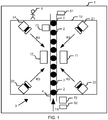
- Fig. 1 shows very schematically a part of a machine 1, which is, for example, a container treatment system, in particular an empty bottle inspection machine, full bottle inspection machine, label inspection device, lid inspection machine, prefom inspection machine, filling height inspection machine, stretch blow molding machine, filling machine, machine for treating glass containers, etc., a packaging system, a crate inspection device, etc. can. Even if the machine 1 is partially described below using the example of a container treatment system, the machine 1 is not restricted to this.
- containers 2 in particular transparent plastic bottles, glass bottles, metal cans, preforms, empty, full, closed, unsealed, labeled, not labeled, etc., are produced and / or treated.
- the container inspection device described below can be connected upstream and / or downstream of each treatment step in the container treatment system.
- Secondary packaging units that are logically assigned to the containers 2, such as beverage crates and containers or pallets, can also be inspected in the machine 1.
- Fig. 1 For the sake of simplicity, not all containers 2 are provided with a reference number.
- the containers 2 are moved in a container stream 3 in which the containers 2 are each arranged individually in a row one after the other with the aid of a transport device 4 through a container inspection device 10 in the direction of an arrow TR.
- the containers 2 are moved past lights 11, 12 and receiving units 21, 22, 23, 24.
- the machine 1 is operated, for example, or simply viewed by a person 5.
- Light barriers 71, 72 and / or rotary encoders 81, 82 can detect states of the containers 2 on the transport device 4 or only a movement, in particular rotation, of the transport device 4 without the container 2.
- the light barriers 71, 72 and / or rotary encoders 81, 82 can be used to detect the path of the container 2 and thus to determine the speed of the container flow 3.
- the light barriers 71, 72 and / or rotary encoders 81, 82 are arranged, for example, in a decentralized manner, in particular at the inlet and / or outlet of the container 2 into / out of the container inspection device 10.
- the lamp 11 is arranged between the receiving units 21, 22 on one side of the container flow 3.
- the lamp 12 is arranged between the receiving units 23, 24 on the other side of the container flow 3.
- the container 2 can thus be illuminated from two different sides.
- the recording units 23, 24 are positioned in such a way that they can record images of each of the containers 2 from, for example, the four directions R1, R2, R4, R5 shown in FIG Fig. 1 are represented by an arrow. If necessary, the recording units 21, 22, 23, 24 can also be positioned differently, so that, for example, images are recorded from diagonally above above the lamp 11 or diagonally below below the lamp 12, and / or images at different heights of the container 2, etc. .
- the Recording units 21 to 24 can record images, for example, which are evaluated to detect errors, defects, etc. of the container 2.
- the recording units 21 to 24 can be cameras.
- the light source all types of electrical light sources are used.
- LED lamps incandescent, halogen, fluorescent, high-pressure discharge and low-pressure discharge lamps can also be used.
- the wavelength of the light sources covers the range of radiation with a frequency in the Tera-Hertz range up to the range of the wavelength of X-rays.
- Fig. 2 shows a special embodiment of the container inspection device 10 in more detail.
- a bus system 6 is provided in the machine 1, to which many of the components of the machine 1 are connected.
- connecting lines 7, 8, 9 are provided.
- the bus system 6 is, in particular, an Ethernet real-time field bus.
- the bus system 6 provides a real-time data network.
- connection line 7 can in particular be implemented for the GigEVision® standard.
- connection line 8 can connect a recording unit 25 to an image recording system 40 via a USB interface.
- a connection via alternative vision protocols such as FireWire or CoaXPress would be possible with the connection line 9.
- the container inspection device 10 has the first lamp 11 with an energy buffer 111, a second lamp 12 with an energy buffer 121, a third lamp 13 with an energy buffer 131, a fourth lamp 14 with an energy buffer 141, a fifth lamp 15 with an energy buffer 151 and a first and second light field 152, 153, the first and second recording unit 21, 22, a fifth recording unit 25 and a sixth recording unit 26, the recording units 21, 22, 25 , 26 form a detection system and / or can each be implemented quite generally as an optical detection device, an optional power injector or electrical energy supply 30, a bus system controller 35, an image recording system 40 with a connection module 41 and to which an electrical line 50 is connected is, and a general user interface 55.
- the signals of the light barriers 71, 72 and / or rotary encoders 81, 82 can be passed on to the bus system controller 35, even if this is shown in FIG Fig. 2 is not shown.
- the lamp 15 can also have more than two luminous fields 152, 153, which can be controlled separately from one another and can therefore light up separately from one another.
- lighting can be controlled in relation to the color and / or brightness curve.
- the intermediate energy stores 111, 121, 131, 141, 151 are designed in such a way that the assigned light 11 to 15 or flashing light from the respective intermediate energy store 111, 121, 131, 141, 151 can briefly draw an amount of energy that is higher than that of the energy provided to the electrical energy supply at the time of extraction.
- the intermediate energy store 111 or the other intermediate energy stores of the lights 12 to 15 at least one light 11 to 14 and / or a light 15 with at least two separate light fields 152, 153 can be at least temporarily simultaneously and / or in quick succession and / or with different duration and / or different electrical currents for flashing with energy.
- the lights 11 to 15 thus form a flash unit which provides a great deal of light for a very short time or in a pulsed manner.
- the light pulse does not last very long, at full power usually only a few thousandths of a second, as previously described in the introduction to the description.
- the optional power injector or the electrical power supply 30 can take over or supplement the power supply of the lights 11 to 15 instead of the power supply unit provided in the connection module 41 for supplying a voltage U and be looped into the real-time bus system 6 at any point. Are very If many lights 11 to 15 or other consumers are connected to the line for the real-time bus system 6, the electrical power supply can be fed in at several points.
- connection module 41 is used to connect the electrical line 50, via which an electrical energy supply with the voltage U and the trigger signal TG1 are routed to different wires or wire pairs.
- the image recording system 40 also has connections 43, 44 for connecting both the bus system controller 35 and the line of the bus system 6, for example each via a data connector such as an RJ-45 connector.
- the image recording system 40 with its connections 42, 45 and 46 shows various connection options for a wide variety of camera interfaces, such as USB Vision Camera Link, CoaXPress, GigEVision or others, with the help of the connection lines 7, 8 and 9 ..
- the real-time bus system 6 and the connection lines 7, 8 , 9 are clearly separated from one another via an I / O module or input / output module 48.
- the general user interface 55 can be implemented as a personal computer (PC) and can also be referred to as a GUI PC. With the general user interface 55, the person 5 can operate and monitor the container inspection device 10.
- a real-time bus is used to trigger the lighting with at least one of the lights 11 to 15, e.g. B. EtherCat, used in connection with the electrical supply of the lighting in a cable of the bus system 6. If the lighting also needs to be configured, this can be done with the same real-time bus.
- the electrical line for the bus system 6 thus leads both the energy supply for lighting with the lights 11 to 15, as well as the communication of the real-time bus to the lights 11 to 15.
- the electrical line for the bus system 6 consists of at least two or more wires or Wire pairs.
- the electrical energy supply can use the same wires as the communication, or part of these wires. It can also be routed through separate wires in the line.
- the electrical line for the bus system 6 can be designed as a data cable, of which at least one wire pair is provided for connection to the electrical power supply and at least one wire pair is provided for connection to the bus system.
- the lights 11 to 15 receive the electrical line for the bus system 6 as a connecting line or cable, further lines or cables not being necessary.
- the lights 11 to 15 can, however, each have a further connection. This connects another lamp of the lamps 11 to 15, etc. via a second line for the bus system 6, so that a kind of chain is created.
- the real-time bus system 6 is not reserved exclusively for the lights 11 to 15.
- B. measuring devices can be included as participants, which deliver the stimuli for the inspection of containers 2. These include different sensors, such as B. the light barriers 71, 72, IR sensors, HF caustic sensors, the rotary encoders 81, 82, distance sensors, metal sensors, color sensors etc.
- the sensors can be connected directly to the real-time bus system 6 via their own interface, or via an input / Output device to be connected to the real-time bus system 6. It is possible that these sensors or input / output devices are also fed with the aid of the energy supply located in the line of the real-time bus system 6.
- At least one recording unit 21, 22, 25, 26 of the image recording system 40 is connected to the same real-time bus system 6 with a real-time interface.
- An image recording system 40 can support one recording unit 21, 22, 25, 26 or several independent recording units 21, 22, 25, 26.
- the interface between recording unit 21, 22, 25, 26 and image recording system 40 can be designed differently.
- Typical interfaces between image recording system 40 and recording units 21, 22, 25, 26 can be an open standard, such as GigE Vision, USB, Camera Link, or others, but also a proprietary interface.
- the imaging system 40 could be an intelligent camera with a real-time bus interface.
- due to the configuration described above and below within the image recording system 40 it is strictly ensured that the bus system 6 and the network in connection with the connection line 7 are separate from one another, that is, are not the same or the same.
- the real-time bus system 6 ensures that data is sent and received in a finite time and with a short response time or delay time T D.
- the real-time bus system 6 offers the ability that several or all participants connected to the real-time bus system 6 work synchronously, similar to a computer network.
- the data is sent in a so-called frame or message.
- the real-time bus system 6 ensures that the frame is exchanged cyclically among all participants, such as lights 11 to 15, sensors, etc.
- the cycle time for sending a frame in the real-time bus system 6 can be from less than one millisecond to several milliseconds. Typical for the inspection technology are 0.5-10ms, ideally 1-2ms.
- the real-time bus system 6 can synchronize the participants down to a few nanoseconds.
- devices such as the subscribers of the real-time bus system 6, in particular the lights 11 to 15 and the recording units 21, 22, 25, 26, can execute actions in the single-digit microsecond range that are synchronous with one another.
- the action can be distributed over several devices, such as the participants in the real-time bus system 6, in particular the lights 11 to 15 and the recording units 21, 22, 25, 26, extremely synchronously via the real-time bus system 6 within a very short reaction time between stimuli and the derived action be performed.
- An action in the sense of the present description is the synchronous execution of the exposure with the respective recording unit 21, 22, 25, 26 and the lamp flash of the lights 11 to 15.
- the devices are 1000 times more precisely synchronized with each other than the cycle time, as there is synchronicity with respect to the devices in the ⁇ s range instead of ms.
- reaction time between stimuli and action and synchronicity, the time of execution in at least two different devices.
- the reaction time is the time that elapses in the overall system until at least one action from input stimuli reaches the executing device.
- the real-time bus system 6 used in the container inspection device 10 offers both.
- the bus system 6 of the container inspection device 10 is designed so that a trigger signal TG1, TG2 triggers any lights of the lights 11 to 15 or any light fields of the light fields 152, 153 of the light 11 or any combinations of the recording units 21 to 26 and flash or exposure time combinations can.
- a trigger signal TG1, TG2 triggers any lights of the lights 11 to 15 or any light fields of the light fields 152, 153 of the light 11 or any combinations of the recording units 21 to 26 and flash or exposure time combinations can.
- the combination of triggering the recording unit 25 and simultaneously activating the lamp 12, which is in particular a transmitted light lamp, during an exposure time of 100 ⁇ s of the recording unit 25 for a period of 100 ⁇ s, and at the same time the lamp 13, which is in particular a reflected light lamp, is conceivable to let flash for a period of 50 ⁇ s.
- Another possible embodiment of the container inspection device 10 is that, via the ⁇ s-precise control of the image recording with one of the recording units 21 to 26, the brightness of the recorded image via the flash length and / or energy of one of the lights 11 to 15 or a light field of the light fields 152, 153 the lamp 15 can be achieved.
- Another possible embodiment is that different light fields 152, 153 of the lamp 15 are triggered at different times during a recording with the recording unit 26. This is necessary, for example, when patterns and / or contrasting edges of a container 2 or its label or closure etc. have to be generated in a targeted manner.
- Another configuration option is the targeted switching on of different color spectra by means of, for example, the lamp 12, whereby the switching on of the red-green-blue spectrum (RGB spectrum) by means of a light-emitting diode (LED) can be mentioned as well as the near IR spectrum and / or the UV spectrum.
- RGB spectrum red-green-blue spectrum
- LED light-emitting diode
- the bus system 6 is designed in such a way that a change in the bus topology, that is to say adding or removing a bus subscriber during operation of the container inspection device 10, is possible ("hot-plug").
- the container inspection device 10 is modularly expandable. These properties are particularly advantageous because they make a standstill of the container treatment system as a machine 1 as short as possible, for example when changing types.
- the container inspection device 10 has a very robust structure, both mechanically and thermally and with regard to the EMC protective measures to be observed.
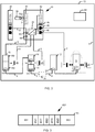
- Fig. 3 shows a frame 65 for a transmission of data in the bus system 6 of the container inspection device 10 according to a second embodiment.
- the container inspection device 10 and the associated machine 1 are largely designed in the same way as described in relation to the first embodiment.
- the frame 65 in Fig. 3 has a frame head 651, a data part 652 and a frame end 652.
- the data part has data blocks 6521 through 6525.
- the real-time bus system 6 sends the frame 65 cyclically to all participants after the cycle time has elapsed. If the reaction time, cycle time is sufficient, in the sense of the shortest point in time between stimuli and action, but the granularity of the cycle time in the application is not yet sufficient, a data block 6521 to 6525 in the data part 652 can be interpreted as oversampling for a specific participant. This is explained using the following example.
- a trigger TG1 should be triggered in 1.6ms.
- the cycle time is 1 ms.
- the trigger TG1 can be triggered in one millisecond or after two milliseconds.
- oversampling can be carried out. I.e. each value stands for an execution time in a 0.2 ms grid.
- the information [0,0,0,1,0] would mean oversampling of the trigger time. This makes it possible to execute a trigger in 1.6 ms with a time resolution of 200 ⁇ s, although the cycle of the bus system 6 in the example is 1 ms.
- this example describes five-fold oversampling, the oversampling could be decreased or increased in the data portion 652.
- the oversampling does not have to be the same for all participants in the real-time bus system 6. Participants with greater oversampling, others with none, nor others with less oversampling could be operated in the same real-time bus.
- the oversampling is interpreted as a number instead of the binary digitization described above.
- a granularity of 256 levels could be achieved with 8 binary digits.
- the granularity would then be approx. 3.9 ⁇ s.
- oversampling is interpreted as a "time slice" (second embodiment) or value (modification of the second embodiment) is only a matter of necessity. Both are possible. Both have advantages. So can with the same Memory usage, the granularity can be increased or several flashes can be triggered in quick succession with one of the lights 11 to 15.
- the recording unit 21 “receives” the information [0,0,1,0,0] in the data part 652 and therefore records a recording with the illumination of the lamp 11 at the time 400 ⁇ s.
- the recording unit 22 “receives” the information [0,0,0,0,1] in the data part 652 and records a recording with the same illumination at the time 800 ⁇ s. In practice, the information is separated in the image recording system 40 and fed into the correct connection lines 7 for the recording units 21, 22.
- the container inspection device 10 is designed in the same way as described in the first exemplary embodiment.
- the container inspection device 10 can also have only one lamp, for example the first lamp 11, or two lamps. Alternatively, the container inspection device 10 can also have more than the five lights shown. In addition, the container inspection device 10 can also have only one receiving unit, for example the first receiving unit 21. Alternatively, the container inspection device 10 can also have more than six receiving units.
- At least one of the lights 11 to 15 can also be controlled in such a way that the power P for a flash of the lights 11 to 15 increases continuously over time.
- another lamp of the lamps 11 to 15 can also be controlled in such a way that the output of the lamp 11 to 15 decreases continuously over the time t.
- Other variants are also conceivable here.
- the lights 11 to 15 can be controlled with the maximum power of the lights 11 to 15 when the container flow 3 is illuminated, if one or more of the recording units 21 to 26 is to perform optical detection or image recording.
Landscapes
- Immunology (AREA)
- General Health & Medical Sciences (AREA)
- Life Sciences & Earth Sciences (AREA)
- Chemical & Material Sciences (AREA)
- Physics & Mathematics (AREA)
- Biochemistry (AREA)
- Health & Medical Sciences (AREA)
- General Physics & Mathematics (AREA)
- Analytical Chemistry (AREA)
- Pathology (AREA)
- Engineering & Computer Science (AREA)
- Structural Engineering (AREA)
- Civil Engineering (AREA)
- Architecture (AREA)
- Investigating Materials By The Use Of Optical Means Adapted For Particular Applications (AREA)
- Testing Or Calibration Of Command Recording Devices (AREA)
Applications Claiming Priority (2)
| Application Number | Priority Date | Filing Date | Title |
|---|---|---|---|
| DE102015106013.2A DE102015106013B4 (de) | 2015-04-20 | 2015-04-20 | Behälterinspektionsvorrichtung und Behälterinspektionsverfahren zur Inspektion von Behältern |
| PCT/EP2016/052635 WO2016169667A1 (de) | 2015-04-20 | 2016-02-08 | Behälterinspektionsvorrichtung und behälterinspektionsverfahren zur inspektion von behältern |
Publications (2)
| Publication Number | Publication Date |
|---|---|
| EP3286552A1 EP3286552A1 (de) | 2018-02-28 |
| EP3286552B1 true EP3286552B1 (de) | 2021-01-20 |
Family
ID=55398267
Family Applications (1)
| Application Number | Title | Priority Date | Filing Date |
|---|---|---|---|
| EP16705063.2A Active EP3286552B1 (de) | 2015-04-20 | 2016-02-08 | Behälterinspektionsvorrichtung und behälterinspektionsverfahren zur inspektion von behältern |
Country Status (6)
| Country | Link |
|---|---|
| US (1) | US10261029B2 (zh) |
| EP (1) | EP3286552B1 (zh) |
| CN (1) | CN107667286B (zh) |
| AT (1) | AT16388U3 (zh) |
| DE (2) | DE102015106013B4 (zh) |
| WO (1) | WO2016169667A1 (zh) |
Cited By (1)
| Publication number | Priority date | Publication date | Assignee | Title |
|---|---|---|---|---|
| EP4328680A1 (de) * | 2022-08-17 | 2024-02-28 | Krones AG | Vorrichtung und verfahren zum inspizieren von behältnissen |
Families Citing this family (7)
| Publication number | Priority date | Publication date | Assignee | Title |
|---|---|---|---|---|
| FR3056297B1 (fr) * | 2016-09-19 | 2018-10-05 | Tiama | Dispositif pour l'inspection optique de recipients en verre en sortie de machine de formage |
| US10422755B2 (en) * | 2016-12-07 | 2019-09-24 | Applied Vision Corporation | Identifying defects in transparent containers |
| DE102016124266A1 (de) * | 2016-12-13 | 2018-06-14 | Krones Ag | Etikettiermaschine, Druckmaschine, Inspektionsmaschine und Verfahren zur Inbetriebnahme eines Bussystems in einer solchen Maschine |
| DE102017008406B4 (de) * | 2017-09-07 | 2023-07-20 | Heuft Systemtechnik Gmbh | Inspektionsvorrichtung und ein Verfahren mit Farbbeleuchtung |
| EP3537707B1 (de) * | 2018-03-06 | 2021-07-28 | B&R Industrial Automation GmbH | Kamerakern einer smart kamera für die industrielle bildverarbeitung und verfahren zur industriellen bildverarbeitung |
| DE102018107689A1 (de) * | 2018-03-29 | 2019-10-02 | Krones Ag | Verfahren und Vorrichtung zum Inspizieren von Behältnissen |
| FR3109444B1 (fr) * | 2020-04-16 | 2022-04-29 | Tiama | Poste et procédé pour détecter en translation des défauts de glaçures sur des récipients en verre |
Family Cites Families (18)
| Publication number | Priority date | Publication date | Assignee | Title |
|---|---|---|---|---|
| AU553069B2 (en) | 1981-07-17 | 1986-07-03 | W.R. Grace & Co.-Conn. | Radial scan, pulsed light article inspection ccv system 0 |
| US6720745B2 (en) | 1997-08-26 | 2004-04-13 | Color Kinetics, Incorporated | Data delivery track |
| US20050174473A1 (en) | 1999-11-18 | 2005-08-11 | Color Kinetics, Inc. | Photography methods and systems |
| DE10017126C1 (de) | 2000-04-06 | 2001-06-13 | Krones Ag | Verfahren und Vorrichtung zum optischen Überprüfen transparenter Behälter |
| DE10027226C1 (de) * | 2000-05-31 | 2001-10-18 | Krones Ag | Verfahren und Vorrichtung zum Inspizieren transparenter Behälter |
| KR100626390B1 (ko) | 2005-02-07 | 2006-09-20 | 삼성전자주식회사 | 자기 메모리 소자 및 그 형성 방법 |
| CN201053954Y (zh) * | 2007-05-15 | 2008-04-30 | 广州市万世德包装机械有限公司 | 一种用于高速运行中玻璃空瓶透明异物的检测装置 |
| US7915570B2 (en) * | 2007-08-03 | 2011-03-29 | National Instruments Corporation | Smart camera with an integrated lighting controller |
| DE102008062064A1 (de) * | 2008-12-12 | 2010-06-17 | Krones Ag | Verfahren zur Steuerung einer Maschine zur Behandlung von Behältern |
| DE102010043635A1 (de) * | 2010-11-09 | 2012-05-10 | Krones Aktiengesellschaft | Vorrichtung zum Inspizieren von Behältern |
| WO2012097142A2 (en) * | 2011-01-12 | 2012-07-19 | Tait Towers, Inc. | System for providing power and control signals to devices |
| CH705372B1 (de) * | 2011-08-02 | 2015-06-15 | Ws Projektentwicklungs Ag | Kompaktanlage zur Bereitstellung von Wärmeenergie an einen Verbraucher mit einem Heizsystem. |
| DE102011083757A1 (de) * | 2011-09-29 | 2013-04-04 | Krones Aktiengesellschaft | Triggerlichtgitter und Verfahren zur Positionsbestimmung von Behältern |
| DE102012104223A1 (de) * | 2012-03-12 | 2013-09-12 | H. Leiter Gmbh | Verfahren und Vorrichtung zur optischen Erkennung in einer Sortieranlage |
| CN202486066U (zh) * | 2012-03-22 | 2012-10-10 | 厦门大学 | 基于机器视觉的铝箔针孔检测系统 |
| CN103913460A (zh) * | 2013-01-04 | 2014-07-09 | 北京兆维电子(集团)有限责任公司 | 一种在线纸病检测系统 |
| DE102013106894A1 (de) * | 2013-07-01 | 2015-01-08 | Krones Ag | Behälterinspektionsvorrichtung und Behälterinspektionsverfahren zur Inspektion von Behältern |
| CN104483329A (zh) * | 2014-11-27 | 2015-04-01 | 成都北斗在线检测设备有限公司 | 一种铝箔针孔在线检测系统及其检测方法 |
-
2015
- 2015-04-20 DE DE102015106013.2A patent/DE102015106013B4/de active Active
- 2015-04-20 DE DE202015009702.2U patent/DE202015009702U1/de active Active
-
2016
- 2016-02-08 WO PCT/EP2016/052635 patent/WO2016169667A1/de active Application Filing
- 2016-02-08 CN CN201680022944.6A patent/CN107667286B/zh active Active
- 2016-02-08 AT ATGM50060/2019U patent/AT16388U3/de unknown
- 2016-02-08 EP EP16705063.2A patent/EP3286552B1/de active Active
- 2016-02-08 US US15/567,511 patent/US10261029B2/en active Active
Non-Patent Citations (1)
| Title |
|---|
| None * |
Cited By (1)
| Publication number | Priority date | Publication date | Assignee | Title |
|---|---|---|---|---|
| EP4328680A1 (de) * | 2022-08-17 | 2024-02-28 | Krones AG | Vorrichtung und verfahren zum inspizieren von behältnissen |
Also Published As
| Publication number | Publication date |
|---|---|
| CN107667286A (zh) | 2018-02-06 |
| DE102015106013A1 (de) | 2016-10-20 |
| CN107667286B (zh) | 2020-10-02 |
| DE102015106013B4 (de) | 2024-02-08 |
| EP3286552A1 (de) | 2018-02-28 |
| DE202015009702U1 (de) | 2019-05-02 |
| AT16388U3 (de) | 2020-05-15 |
| US20180136142A1 (en) | 2018-05-17 |
| US10261029B2 (en) | 2019-04-16 |
| WO2016169667A1 (de) | 2016-10-27 |
| AT16388U2 (de) | 2019-08-15 |
Similar Documents
| Publication | Publication Date | Title |
|---|---|---|
| EP3286552B1 (de) | Behälterinspektionsvorrichtung und behälterinspektionsverfahren zur inspektion von behältern | |
| WO2016166062A1 (de) | Steuermodul für eine kamera in einem produktionssystem und verfahren zum erfassen von bildern mittels einer solchen kamera | |
| DE102014220598B4 (de) | Inspektionsvorrichtung und Verfahren zur Durchlichtinspektion von Behältern | |
| DE69924427T2 (de) | Optischer Schalter mit mehreren optischen Achsen und Verfahren zum Anzeigen dessen Zustand | |
| DE112012002055T5 (de) | Lichtquelle, LED-Impulssteuerung und Verfahren zur programmierbaren Impulssteurung und Synchronisierung von Leuchtvorrichtungen | |
| EP3374760B1 (de) | Vorrichtung und verfahren zur überwachung einer laufenden warenbahn | |
| DE102010024784A1 (de) | Multisensorielle Anordnung für die optische Inspektion und Sortierung von Schüttgütern | |
| EP1189052A2 (de) | Vorrichtung zum bildlichen Erfassen von Stückgütern | |
| EP3483617B1 (de) | Verfahren zur latenzmessung | |
| EP2720098A1 (de) | Sicherheitssystem für eine Anlage umfassend einen Testsignalpfad mit Hin- und Rückleitungspfad | |
| DE102018119182C5 (de) | Vorrichtung und Verfahren zur Steuerung der Beleuchtung bei Industriekamerasystemen | |
| EP3425324B1 (de) | Verfahren zur parametrierung eines sensors | |
| EP1596221B1 (de) | Verfahren und Vorrichtung zur Entfernungsmessung | |
| WO2019185185A1 (de) | Verfahren und vorrichtung zum inspizieren von behältnissen | |
| DE102017127236B4 (de) | Sensor-steuerungsvorrichtung und sensorsystem | |
| EP2299249A1 (de) | Anordnung und Verfahren zur Vermeidung oder Verringerung der Schädigung von strahlungsempfindlichen Exponaten in Ausstellungen oder Museen | |
| DE2705936A1 (de) | Verfahren und anordnung zur elektronischen bildanalyse | |
| DE10025897B4 (de) | Verfahren zum Betreiben einer optoelektronischen Sensoranordnung und optoelektronische Sensoranordnung | |
| WO2007104417A2 (de) | Datenübertragung in einem system aus textiltechnischen baueinheiten | |
| DE102011111355B4 (de) | Verfahren und Vorrichtung zur Pulsbeleuchtung für ein Bildverarbeitungssystem | |
| DE102017004030B4 (de) | Verfahren und Vorrichtung zum Sichern eines Arbeitsraums | |
| DE102009053135B4 (de) | Empfänger für ein Lichtgitter und Verfahren zum Betreiben des Empfängers | |
| WO2008009306A1 (de) | Beleuchtungssystem mit lichtsensor zur vorschaltgerätsteuerung | |
| DE102022120823A1 (de) | Vorrichtung und Verfahren zum Inspizieren von Behältnissen | |
| DE102008006457A1 (de) | Verfahren und Vorrichtung für die Kontaktierung eines elektrischen Leiters |
Legal Events
| Date | Code | Title | Description |
|---|---|---|---|
| STAA | Information on the status of an ep patent application or granted ep patent |
Free format text: STATUS: THE INTERNATIONAL PUBLICATION HAS BEEN MADE |
|
| PUAI | Public reference made under article 153(3) epc to a published international application that has entered the european phase |
Free format text: ORIGINAL CODE: 0009012 |
|
| STAA | Information on the status of an ep patent application or granted ep patent |
Free format text: STATUS: REQUEST FOR EXAMINATION WAS MADE |
|
| 17P | Request for examination filed |
Effective date: 20171012 |
|
| AK | Designated contracting states |
Kind code of ref document: A1 Designated state(s): AL AT BE BG CH CY CZ DE DK EE ES FI FR GB GR HR HU IE IS IT LI LT LU LV MC MK MT NL NO PL PT RO RS SE SI SK SM TR |
|
| AX | Request for extension of the european patent |
Extension state: BA ME |
|
| DAV | Request for validation of the european patent (deleted) | ||
| DAX | Request for extension of the european patent (deleted) | ||
| STAA | Information on the status of an ep patent application or granted ep patent |
Free format text: STATUS: EXAMINATION IS IN PROGRESS |
|
| 17Q | First examination report despatched |
Effective date: 20190531 |
|
| GRAP | Despatch of communication of intention to grant a patent |
Free format text: ORIGINAL CODE: EPIDOSNIGR1 |
|
| STAA | Information on the status of an ep patent application or granted ep patent |
Free format text: STATUS: GRANT OF PATENT IS INTENDED |
|
| RIC1 | Information provided on ipc code assigned before grant |
Ipc: E06B 9/06 20060101ALI20200910BHEP Ipc: G01N 21/90 20060101ALI20200910BHEP Ipc: G01N 21/88 20060101AFI20200910BHEP Ipc: E06B 3/48 20060101ALI20200910BHEP Ipc: E06B 9/15 20060101ALI20200910BHEP |
|
| RIC1 | Information provided on ipc code assigned before grant |
Ipc: G01N 21/88 20060101AFI20200921BHEP Ipc: G01N 21/90 20060101ALI20200921BHEP |
|
| INTG | Intention to grant announced |
Effective date: 20201012 |
|
| GRAS | Grant fee paid |
Free format text: ORIGINAL CODE: EPIDOSNIGR3 |
|
| GRAA | (expected) grant |
Free format text: ORIGINAL CODE: 0009210 |
|
| STAA | Information on the status of an ep patent application or granted ep patent |
Free format text: STATUS: THE PATENT HAS BEEN GRANTED |
|
| AK | Designated contracting states |
Kind code of ref document: B1 Designated state(s): AL AT BE BG CH CY CZ DE DK EE ES FI FR GB GR HR HU IE IS IT LI LT LU LV MC MK MT NL NO PL PT RO RS SE SI SK SM TR |
|
| REG | Reference to a national code |
Ref country code: GB Ref legal event code: FG4D Free format text: NOT ENGLISH |
|
| REG | Reference to a national code |
Ref country code: CH Ref legal event code: EP |
|
| REG | Reference to a national code |
Ref country code: AT Ref legal event code: REF Ref document number: 1356830 Country of ref document: AT Kind code of ref document: T Effective date: 20210215 |
|
| REG | Reference to a national code |
Ref country code: IE Ref legal event code: FG4D Free format text: LANGUAGE OF EP DOCUMENT: GERMAN |
|
| REG | Reference to a national code |
Ref country code: DE Ref legal event code: R096 Ref document number: 502016012241 Country of ref document: DE |
|
| REG | Reference to a national code |
Ref country code: NL Ref legal event code: MP Effective date: 20210120 |
|
| REG | Reference to a national code |
Ref country code: LT Ref legal event code: MG9D |
|
| PG25 | Lapsed in a contracting state [announced via postgrant information from national office to epo] |
Ref country code: HR Free format text: LAPSE BECAUSE OF FAILURE TO SUBMIT A TRANSLATION OF THE DESCRIPTION OR TO PAY THE FEE WITHIN THE PRESCRIBED TIME-LIMIT Effective date: 20210120 Ref country code: GR Free format text: LAPSE BECAUSE OF FAILURE TO SUBMIT A TRANSLATION OF THE DESCRIPTION OR TO PAY THE FEE WITHIN THE PRESCRIBED TIME-LIMIT Effective date: 20210421 Ref country code: FI Free format text: LAPSE BECAUSE OF FAILURE TO SUBMIT A TRANSLATION OF THE DESCRIPTION OR TO PAY THE FEE WITHIN THE PRESCRIBED TIME-LIMIT Effective date: 20210120 Ref country code: NO Free format text: LAPSE BECAUSE OF FAILURE TO SUBMIT A TRANSLATION OF THE DESCRIPTION OR TO PAY THE FEE WITHIN THE PRESCRIBED TIME-LIMIT Effective date: 20210420 Ref country code: PT Free format text: LAPSE BECAUSE OF FAILURE TO SUBMIT A TRANSLATION OF THE DESCRIPTION OR TO PAY THE FEE WITHIN THE PRESCRIBED TIME-LIMIT Effective date: 20210520 Ref country code: BG Free format text: LAPSE BECAUSE OF FAILURE TO SUBMIT A TRANSLATION OF THE DESCRIPTION OR TO PAY THE FEE WITHIN THE PRESCRIBED TIME-LIMIT Effective date: 20210420 Ref country code: LT Free format text: LAPSE BECAUSE OF FAILURE TO SUBMIT A TRANSLATION OF THE DESCRIPTION OR TO PAY THE FEE WITHIN THE PRESCRIBED TIME-LIMIT Effective date: 20210120 |
|
| PG25 | Lapsed in a contracting state [announced via postgrant information from national office to epo] |
Ref country code: SE Free format text: LAPSE BECAUSE OF FAILURE TO SUBMIT A TRANSLATION OF THE DESCRIPTION OR TO PAY THE FEE WITHIN THE PRESCRIBED TIME-LIMIT Effective date: 20210120 Ref country code: RS Free format text: LAPSE BECAUSE OF FAILURE TO SUBMIT A TRANSLATION OF THE DESCRIPTION OR TO PAY THE FEE WITHIN THE PRESCRIBED TIME-LIMIT Effective date: 20210120 Ref country code: LV Free format text: LAPSE BECAUSE OF FAILURE TO SUBMIT A TRANSLATION OF THE DESCRIPTION OR TO PAY THE FEE WITHIN THE PRESCRIBED TIME-LIMIT Effective date: 20210120 Ref country code: PL Free format text: LAPSE BECAUSE OF FAILURE TO SUBMIT A TRANSLATION OF THE DESCRIPTION OR TO PAY THE FEE WITHIN THE PRESCRIBED TIME-LIMIT Effective date: 20210120 |
|
| PG25 | Lapsed in a contracting state [announced via postgrant information from national office to epo] |
Ref country code: IS Free format text: LAPSE BECAUSE OF FAILURE TO SUBMIT A TRANSLATION OF THE DESCRIPTION OR TO PAY THE FEE WITHIN THE PRESCRIBED TIME-LIMIT Effective date: 20210520 |
|
| REG | Reference to a national code |
Ref country code: DE Ref legal event code: R097 Ref document number: 502016012241 Country of ref document: DE |
|
| REG | Reference to a national code |
Ref country code: BE Ref legal event code: MM Effective date: 20210228 |
|
| PG25 | Lapsed in a contracting state [announced via postgrant information from national office to epo] |
Ref country code: CZ Free format text: LAPSE BECAUSE OF FAILURE TO SUBMIT A TRANSLATION OF THE DESCRIPTION OR TO PAY THE FEE WITHIN THE PRESCRIBED TIME-LIMIT Effective date: 20210120 Ref country code: EE Free format text: LAPSE BECAUSE OF FAILURE TO SUBMIT A TRANSLATION OF THE DESCRIPTION OR TO PAY THE FEE WITHIN THE PRESCRIBED TIME-LIMIT Effective date: 20210120 Ref country code: LI Free format text: LAPSE BECAUSE OF NON-PAYMENT OF DUE FEES Effective date: 20210228 Ref country code: MC Free format text: LAPSE BECAUSE OF FAILURE TO SUBMIT A TRANSLATION OF THE DESCRIPTION OR TO PAY THE FEE WITHIN THE PRESCRIBED TIME-LIMIT Effective date: 20210120 Ref country code: LU Free format text: LAPSE BECAUSE OF NON-PAYMENT OF DUE FEES Effective date: 20210208 Ref country code: SM Free format text: LAPSE BECAUSE OF FAILURE TO SUBMIT A TRANSLATION OF THE DESCRIPTION OR TO PAY THE FEE WITHIN THE PRESCRIBED TIME-LIMIT Effective date: 20210120 Ref country code: CH Free format text: LAPSE BECAUSE OF NON-PAYMENT OF DUE FEES Effective date: 20210228 |
|
| PLBE | No opposition filed within time limit |
Free format text: ORIGINAL CODE: 0009261 |
|
| STAA | Information on the status of an ep patent application or granted ep patent |
Free format text: STATUS: NO OPPOSITION FILED WITHIN TIME LIMIT |
|
| PG25 | Lapsed in a contracting state [announced via postgrant information from national office to epo] |
Ref country code: SK Free format text: LAPSE BECAUSE OF FAILURE TO SUBMIT A TRANSLATION OF THE DESCRIPTION OR TO PAY THE FEE WITHIN THE PRESCRIBED TIME-LIMIT Effective date: 20210120 Ref country code: RO Free format text: LAPSE BECAUSE OF FAILURE TO SUBMIT A TRANSLATION OF THE DESCRIPTION OR TO PAY THE FEE WITHIN THE PRESCRIBED TIME-LIMIT Effective date: 20210120 Ref country code: DK Free format text: LAPSE BECAUSE OF FAILURE TO SUBMIT A TRANSLATION OF THE DESCRIPTION OR TO PAY THE FEE WITHIN THE PRESCRIBED TIME-LIMIT Effective date: 20210120 |
|
| 26N | No opposition filed |
Effective date: 20211021 |
|
| PG25 | Lapsed in a contracting state [announced via postgrant information from national office to epo] |
Ref country code: AL Free format text: LAPSE BECAUSE OF FAILURE TO SUBMIT A TRANSLATION OF THE DESCRIPTION OR TO PAY THE FEE WITHIN THE PRESCRIBED TIME-LIMIT Effective date: 20210120 Ref country code: ES Free format text: LAPSE BECAUSE OF FAILURE TO SUBMIT A TRANSLATION OF THE DESCRIPTION OR TO PAY THE FEE WITHIN THE PRESCRIBED TIME-LIMIT Effective date: 20210120 Ref country code: IE Free format text: LAPSE BECAUSE OF NON-PAYMENT OF DUE FEES Effective date: 20210208 |
|
| PG25 | Lapsed in a contracting state [announced via postgrant information from national office to epo] |
Ref country code: SI Free format text: LAPSE BECAUSE OF FAILURE TO SUBMIT A TRANSLATION OF THE DESCRIPTION OR TO PAY THE FEE WITHIN THE PRESCRIBED TIME-LIMIT Effective date: 20210120 |
|
| PG25 | Lapsed in a contracting state [announced via postgrant information from national office to epo] |
Ref country code: IS Free format text: LAPSE BECAUSE OF FAILURE TO SUBMIT A TRANSLATION OF THE DESCRIPTION OR TO PAY THE FEE WITHIN THE PRESCRIBED TIME-LIMIT Effective date: 20210520 |
|
| PG25 | Lapsed in a contracting state [announced via postgrant information from national office to epo] |
Ref country code: BE Free format text: LAPSE BECAUSE OF NON-PAYMENT OF DUE FEES Effective date: 20210228 |
|
| PG25 | Lapsed in a contracting state [announced via postgrant information from national office to epo] |
Ref country code: NL Free format text: LAPSE BECAUSE OF NON-PAYMENT OF DUE FEES Effective date: 20210120 Ref country code: CY Free format text: LAPSE BECAUSE OF FAILURE TO SUBMIT A TRANSLATION OF THE DESCRIPTION OR TO PAY THE FEE WITHIN THE PRESCRIBED TIME-LIMIT Effective date: 20210120 |
|
| PG25 | Lapsed in a contracting state [announced via postgrant information from national office to epo] |
Ref country code: HU Free format text: LAPSE BECAUSE OF FAILURE TO SUBMIT A TRANSLATION OF THE DESCRIPTION OR TO PAY THE FEE WITHIN THE PRESCRIBED TIME-LIMIT; INVALID AB INITIO Effective date: 20160208 |
|
| PGFP | Annual fee paid to national office [announced via postgrant information from national office to epo] |
Ref country code: FR Payment date: 20231229 Year of fee payment: 9 |
|
| PGFP | Annual fee paid to national office [announced via postgrant information from national office to epo] |
Ref country code: AT Payment date: 20240125 Year of fee payment: 9 |
|
| PG25 | Lapsed in a contracting state [announced via postgrant information from national office to epo] |
Ref country code: MK Free format text: LAPSE BECAUSE OF FAILURE TO SUBMIT A TRANSLATION OF THE DESCRIPTION OR TO PAY THE FEE WITHIN THE PRESCRIBED TIME-LIMIT Effective date: 20210120 |
|
| PGFP | Annual fee paid to national office [announced via postgrant information from national office to epo] |
Ref country code: DE Payment date: 20231229 Year of fee payment: 9 Ref country code: GB Payment date: 20240108 Year of fee payment: 9 |
|
| PGFP | Annual fee paid to national office [announced via postgrant information from national office to epo] |
Ref country code: IT Payment date: 20240111 Year of fee payment: 9 |