EP3286106B1 - Tête de distribution pour récipient aérosol munie de moyens de blocage - Google Patents
Tête de distribution pour récipient aérosol munie de moyens de blocage Download PDFInfo
- Publication number
- EP3286106B1 EP3286106B1 EP16722802.2A EP16722802A EP3286106B1 EP 3286106 B1 EP3286106 B1 EP 3286106B1 EP 16722802 A EP16722802 A EP 16722802A EP 3286106 B1 EP3286106 B1 EP 3286106B1
- Authority
- EP
- European Patent Office
- Prior art keywords
- dispensing head
- push button
- actuating
- head according
- rib
- Prior art date
- Legal status (The legal status is an assumption and is not a legal conclusion. Google has not performed a legal analysis and makes no representation as to the accuracy of the status listed.)
- Active
Links
Images
Classifications
-
- B—PERFORMING OPERATIONS; TRANSPORTING
- B65—CONVEYING; PACKING; STORING; HANDLING THIN OR FILAMENTARY MATERIAL
- B65D—CONTAINERS FOR STORAGE OR TRANSPORT OF ARTICLES OR MATERIALS, e.g. BAGS, BARRELS, BOTTLES, BOXES, CANS, CARTONS, CRATES, DRUMS, JARS, TANKS, HOPPERS, FORWARDING CONTAINERS; ACCESSORIES, CLOSURES, OR FITTINGS THEREFOR; PACKAGING ELEMENTS; PACKAGES
- B65D83/00—Containers or packages with special means for dispensing contents
- B65D83/14—Containers for dispensing liquid or semi-liquid contents by internal gaseous pressure, i.e. aerosol containers comprising propellant
- B65D83/16—Actuating means
- B65D83/22—Actuating means with means to disable actuation
-
- B—PERFORMING OPERATIONS; TRANSPORTING
- B65—CONVEYING; PACKING; STORING; HANDLING THIN OR FILAMENTARY MATERIAL
- B65D—CONTAINERS FOR STORAGE OR TRANSPORT OF ARTICLES OR MATERIALS, e.g. BAGS, BARRELS, BOTTLES, BOXES, CANS, CARTONS, CRATES, DRUMS, JARS, TANKS, HOPPERS, FORWARDING CONTAINERS; ACCESSORIES, CLOSURES, OR FITTINGS THEREFOR; PACKAGING ELEMENTS; PACKAGES
- B65D83/00—Containers or packages with special means for dispensing contents
- B65D83/14—Containers for dispensing liquid or semi-liquid contents by internal gaseous pressure, i.e. aerosol containers comprising propellant
- B65D83/16—Actuating means
- B65D83/20—Actuator caps
Definitions
- the invention relates to a dispensing head for an aerosol container provided with a valve.
- a dispensing head of the prior art is described in KR 2011 0128672 A .
- the dispensing head is constituted by a cover on which is fixed an actuating member provided with a push button movable between a non-depressed rest position and a depressed operating position.
- the valve is either a female valve or a male valve.
- the dispensing head is provided with a stem which penetrates the valve to actuate it.
- the dispensing stem is an integral part of the valve.
- the actuating member is provided with a locking element pivotable about an axis of rotation between an unlocked position in which it does not block the movement of the pushbutton relative to the cover and a locked position in which it blocks the push button in the rest position by preventing it from entering the actuating position.
- the push button is provided with an outlet duct for the product to be sampled, an outlet duct whose first end is provided with connection means intended to cooperate with the valve of an aerosol container, and whose second end is for spraying the product into the environment.
- the locking element in the locked position, cooperates with a blocking part of the first end of the outlet duct.
- the connecting means are constituted by a nozzle designed to cooperate with the stem of a male valve, the locking element acting, in locked position, on the free end of the nozzle.
- the connecting means are constituted by a rod designed to cooperate with a female valve, the first end of the outlet duct being provided on its outer face with a shoulder designed for the locking element to act. , in locked position, on this shoulder.
- the push button is provided with a rib parallel to the movement of movement of the push button between the rest position and the actuating position.
- the locking element is provided with a bearing surface which in the unlocked position is not in the path traversed by the rib when the push button is moved from the rest position to the actuating position, and which in the locked position is in said path so that the rib abuts against the bearing surface when the push button is moved towards the position of actuation without being able to reach this position.
- the rib can be placed on the inner face of the push button, preferably radially relative to the axis of rotation. The rib can also be placed in alignment with the edge of the push button.
- the pivoting portion has a notch surrounded by a cylinder portion directed towards the push button.
- the push button has on its underside a locking rib parallel to the movement of movement of the push button between the rest position and the actuating position, the height of the cylinder part being chosen so that in the locked position, the upper edge of the cylinder part is in or near contact with the lower edge of the locking rib so that the push button can not move from the rest position to the position actuating.
- “almost in contact” it should be understood that there is a clearance between the top of the cylinder part and the locking rib, this game may even allow the possibility of moving the push-button towards the position of the cylinder. actuation, but only to a very small extent, so that this movement is too short to operate the valve.
- the locking member may be constituted by a pivoting part articulated on the actuating member by means of a hinge.
- the pivoting part may be provided with a control element accessible from the outside of the hood, and a locking surface provided with an arcuate notch whose dimensions are sufficient to let the rod serving to actuate the valve, but not the blocking portion of the first end of the outlet duct.
- the locking surface of the locking member may be surrounded by a cylinder portion dimensioned such that the pivoting portion can not pivot beyond the locked position.
- the cover is provided with a slot in front of which is the control element regardless of the pivoting position of the pivoting part between the unlocked position and the locked position, control element being accessible from the outside by this slot. It is then preferable to provide a plate facing the slot to hide the view of the user inside the hood. The control element is then placed between the slot and the plate.
- the plate can be placed in the hood in which case the pivoting part can be provided with a groove whose width is at least equal to the thickness of the plate and in which takes place the free end of said plate. It is also possible to place the plate on the pivoting part, between the slot and the control element, so that the plate is placed opposite the opening regardless of the pivoting position of the pivoting part.
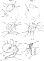
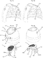
- the dispensing head consists of two main parts: an actuating member (1) and a cover (2).
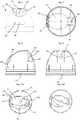
- the hood (2) has a generally shell shape and has a vertical axis of symmetry (A1) schematically represented by the cross on the figure 7 and to which the adjectives "radial” and "axial” are used later.
- An opening (21) for the passage of a pushbutton (11) of the actuating member is formed at the top of the cover.
- the edge of the opening may be marked by a vertical flange (211) directed downwards.
- the hood is provided with an outlet (22) to allow a passage to the product exiting the nozzle of the dispensing head.
- the inner face of the hood is provided with a bead (23) to fix it on the edge crimped with an aerosol bottle.
- the hood is provided with two vertical fixing ribs (24) parallel to each other and placed on either side of the outlet orifice (22). They move away from the hood towards the interior.
- These fixing ribs (24) are each provided with a vertical slot (241) open on the lower edge of the fixing ribs by flaring slightly. In the example presented here, the vertical ribs start at the inside of the hood and end near the opening (21).
- the hood Opposite the outlet (22), the hood is provided with a horizontal slot (25) between the bead (23) and the opening (21).
- a vertical guide plate (26) is placed inside the hood opposite the horizontal slot (25). It is attached by its upper part to the inner face of the cover, above the horizontal slot (25) and extends at least to the lower edge of the slot, or a little lower.
- the plate preferably has the shape of a circular arc. This creates a groove between the guide plate (26) and the inner wall of the cover at the horizontal slot (25).
- the length of the guide plate (26) is chosen so that it conceals the inside of the hood in the view of the user.
- the guide plate (26) protrudes to the right and left of the opening (25), in the second it is the same size and is connected at its ends to the lateral edges of the opening by walls (251).
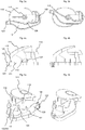
- the actuating member (1) consists essentially of a push-button (11) and a locking element (12), these two elements being connected together by a fixing plate (13).
- the pushbutton (11) consists essentially of an actuating plate (111) which can be curved or curved and whose peripheral edge can extend downwardly by a vertical flange (112). On its underside, the actuating plate is provided with an outlet duct for the product to be sprayed.
- This conduit consists of a first portion (113) and a second portion (114).
- the first portion (113) is substantially vertical and defines a vertical axis of symmetry (A2) schematically marked on the figure 2 by a cross. It should be noted that the push button itself does not necessarily have rotation symmetry.
- the free lower end of the first portion (113) of the outlet duct serves as a connecting end for coupling to the dispensing stem of the valve.
- the free end is slightly flared to facilitate mounting of the dispensing head on the container stem.
- the connection piece is replaced by a rod for actuating the female valve.
- the second portion (114) of the outlet duct may be inclined relative to the first (eg perpendicular) and is attached to the actuating plate (111).
- the free end of the second portion (114) of the outlet conduit terminates in a housing for a nozzle.
- retaining shoulders may be provided on the lower edge of the flange (112).
- the shape of the actuating plate (111) and its flange (112) is complementary to the shape of the opening (21) of the cover and its possible flange, preferably leaving a clearance between the two to avoid any friction.
- the retaining shoulders (when present) deviate from the flange (112) so that in the assembled state, they can not pass through the opening (21) and are retained by it.
- the push button (11) On the underside of the actuating plate (111), the push button (11) is provided with a locking rib (115) parallel to the direction of movement of the pushbutton between the rest position and the position actuating. In practice, this direction is substantially vertical.
- the rib is in the extension of the flange (112), thus in line with the edge of the actuating plate, slightly offset from the plane defined by the two parts (113, 114 ) of the duct.
- this rib is under the actuating plate, preferably in a radial plane, in particular in the plane defined by the two parts (113, 114) of the duct.
- the locking rib (115) is inverted L-shaped. The first branch runs along the actuation plate and the second strikes down.
- the fixing plate (13) has a generally inverted L shape.
- This fixing plate is vertical and preferably has a shape of circular arc whose center can be located on the axis of symmetry (A2).
- the first leg of the L extends horizontally from the lower edge of the second portion (114) of the outlet duct, near its free end. It has on its vertical lateral edges two fins (131) directed towards the center of the actuating member. These fins (131) are parallel to each other.
- the thickness of this first branch is chosen so that in the assembled state, it can penetrate, preferably in force, in the slots (241) of the fastening ribs (24) of the cover.
- the distance separating the fins (131) from the fixing plate is greater than or equal to the distance separating the opposite faces of the two fixing ribs (24).
- the second branch of the L is directed downwards and can end with a support (132).
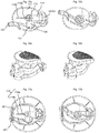
- the locking element (12) consists of a pivoting part (121) articulated on the fixing plate (13), preferably on the support (132), by a hinge (122).
- This articulation can be made in the form of a hinge hinge or a film hinge defining a vertical axis of rotation (A3), that is to say parallel to the axis (A2) defined by the first part (113) of the outlet duct.
- the pivoting portion (121) is provided at its opposite end to the hinge of a control member (123).
- the pivoting portion has just before the control element an upwardly open groove (124) whose width is at least equal to the thickness of the guiding plate (26) of the hood. It would also be possible to place the control element (123) on a vertical plate fixed to the end of the pivoting part (121) so that this plate is placed opposite the opening (25) whatever the position of the control element.
- the guide plate (26) With retaining pads (261) and the groove (124). of a corresponding recess on one of his faces, here a groove (124a).
- a groove (124a) In addition to ensuring contact between the guide plate (26) and one of the walls of the groove (124), it is preferable to provide on the second face of the groove (124) an extra thickness, for example a stud or a molding (124b).
- the pivoting portion (121) has a horizontal bearing surface (125). This bearing surface is provided with a notch (126) arcuate.
- the bearing surface (125) at the notch is placed on the pivoting portion (121) so that it is at the same level (or at a level just below) the lower face of the first portion (113) of the outlet duct when the push button is in the rest position, that is to say not depressed.
- the bearing surface extends from the hinge (122) to the groove (124).
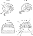
- the notch (126) is surrounded on the side of the bearing surface (thus upward) of a half-cylinder (127) which is not quite above the notch so that there remains a half-circle shoulder (128) around the notch and inside the half-cylinder. This shoulder is clearly visible on figures 11b and 12 . It constitutes a blocking surface.
- the dimensions of the notch are sufficient to allow the dispensing stem of the valve (311) to pass, but not the lower end of the first portion (113) of the passage duct.
- the upper face of the bearing surface (125) is provided with a half-cylinder (127) placed around the notch (126), preferably in line with it. .
- the dimensions of the notch (126) are sufficient to pass the lower end of the first portion (113) of the conduit. There is therefore no blocking shoulder as in the first embodiment.
- the height of the half-cylinder is chosen so that, in the locked position, there is no or very little clearance between the upper edge of the half-cylinder (127) and on the one hand the ridge lower part of the first leg (115a) of the locking rib and secondly the lower edge of the second conduit portion (114).
- the top of the half-cylinder (127) is sufficiently spaced apart so as not to be in the path of the locking rib (115) and the second portion of the duct (114).
- the entire bearing surface (125), or at least this contact portion is sufficiently spaced apart so as not to be in the race of the rib.
- the two components namely the cover (2) and the actuating member (1), are assembled to form the dispensing head, before it is mounted on an aerosol container.
- the locking element (12) is folded back from its visible molding position on the figure 2 until the half-cylinder bears against the first part of the duct (113).
- the locking element pivots around the hinge (122).
- the actuating member (1) is inserted into this position from below into the cover (2) until the fixing plate (13) penetrates into the slots (241) of the fixing ribs and the free end of the second portion (114) of the outlet duct is located opposite the orifice (22) of the hood.
- the push button (11) is placed in the space defined by the edge of the opening (21), with the actuating plate (111) flush with said edge.
- the control element (123) is housed in the groove formed between the cover and the guide plate (26) so as to be able to move freely in it. It enters the slot (25) of the hood, and can even protrude slightly from the hood to be easily grasped from the outside.
- the guide plate (26) penetrates into the groove (124) of the pivoting part of the locking element.
- the junction between the fixing plate (13) and the second portion (114) of the outlet duct constitutes a hinge around which the push-button (11) can pivot in order to actuate the valve.
- the push button (11) In the rest position, the push button (11) is in the high position, that is to say it is flush with the edge of the opening (21). It can be depressed by pivoting around its hinge to actuate the valve.
- the locking member (12) is pivotable about the hinge (122) between a first position, the so-called locked position, in which the control member (123) abuts against a first lateral end of the slot (25), and a second position, said unlocked position, in which the control element (123) abuts against the second lateral end of the slot.
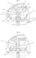
- the half-circle locking shoulder (128) in the locked position, is located under the lower end of the first portion of the conduit. outlet (113), the edge of the notch (126) leaving a passage for the bleed stem of a valve.
- the lower end of the locking rib (115) bears or almost bears on the bearing surface (125).
- this blocking occurs firstly at the contact between the lower end of the first portion of the duct (113) and the locking shoulder (128), as shown by the figures 11b and 12 , and on the other hand at the contact between the lower edge of the locking rib (115) and the bearing surface (125) in the vicinity of the control element (123), as shown by FIG. figure 1a and the figure 13b .
- the half-cylinder (127) is sufficiently spaced to no longer interact with the lower edge of the first portion of conduit (113) as shown for example the figure 5a , or with the lower edge of the first leg (115a) of the locking rib and the lower edge of the second conduit portion (114), as shown for example by the figure 17a .
- the bearing surface (125) is sufficiently spaced from the locking rib (115), to be more precise of the second branch (115b) of the locking rib in the second example, so as not to be in the stroke of this rib during the displacement of the push button (11) in the direction of the valve.
- the actuating member bears against the valve cup, on the one hand at the hinge (122) and on the other side at the lower face of the pivoting part (121) between the notch ( 126) and the groove (124).
- it in the locked position, it is supported at the dome of the cup by a second half-cylinder coaxial with the first (127) and located on the underside of the pivoting portion (121) or a bottom wall.
- the half-cylinder (127) it is possible to size the half-cylinder (127) so that its ends exceed the arc by 180 ° so that the entrance slot thus formed is slightly narrower than the diameter of the lower end of the first portion of conduit (113).
- the ends are, however, sufficiently flexible so that it takes only a slight effort to remake the conduit out of the half-cylinder.
- the term half-cylinder must be understood in a wider sense than a cylinder of angular development equal to 180 °.
- the locking element may be an insert attached to the push button by a hinge hinge, it is also possible to mold the entire actuating member in one piece.
- the blocking element is molded in a position apart, for example between 45 ° and 90 °, from its normal position (locked / unlocked) to give access to the bottom of the pushbutton. This is the position represented in figure 2 .
- the dispensing head consists of only two pieces.
- FIGS 11a and 11b show the dispensing head (1) of the invention mounted on an aerosol container (3) provided with a male valve (31).
- the tip located at the lower end of the first pipe portion (113) is fitted on the stem (311) of the valve.
- the cover is fixed on the container (3) by its bead (23) engaged behind a shoulder of the housing (32).
- the exemplary embodiments show dispensing heads with two locking means. It goes without saying that it would be possible to provide only a locking shoulder (128), a rib resting on the bearing surface (125) or a rib resting on the half-cylinder, see even a support of the second part of leads on the top of the half-cylinder.
Landscapes
- Chemical & Material Sciences (AREA)
- Dispersion Chemistry (AREA)
- Engineering & Computer Science (AREA)
- Mechanical Engineering (AREA)
- Containers And Packaging Bodies Having A Special Means To Remove Contents (AREA)
- Nozzles (AREA)
Priority Applications (1)
| Application Number | Priority Date | Filing Date | Title |
|---|---|---|---|
| PL16722802T PL3286106T3 (pl) | 2015-04-24 | 2016-04-22 | Głowica dozująca do pojemnika aerozolowego zaopatrzona w środki blokujące |
Applications Claiming Priority (2)
| Application Number | Priority Date | Filing Date | Title |
|---|---|---|---|
| FR1553681A FR3035380B3 (fr) | 2015-04-24 | 2015-04-24 | Tete de distribution pour recipient aerosol munie de moyens de blocage |
| PCT/EP2016/059100 WO2016170169A1 (fr) | 2015-04-24 | 2016-04-22 | Tête de distribution pour récipient aérosol munie de moyens de blocage |
Publications (2)
| Publication Number | Publication Date |
|---|---|
| EP3286106A1 EP3286106A1 (fr) | 2018-02-28 |
| EP3286106B1 true EP3286106B1 (fr) | 2019-09-25 |
Family
ID=55970959
Family Applications (1)
| Application Number | Title | Priority Date | Filing Date |
|---|---|---|---|
| EP16722802.2A Active EP3286106B1 (fr) | 2015-04-24 | 2016-04-22 | Tête de distribution pour récipient aérosol munie de moyens de blocage |
Country Status (11)
| Country | Link |
|---|---|
| US (1) | US10364091B2 (pl) |
| EP (1) | EP3286106B1 (pl) |
| BR (1) | BR112017022756B1 (pl) |
| CA (1) | CA2983457C (pl) |
| CU (1) | CU20170130A7 (pl) |
| ES (1) | ES2759608T3 (pl) |
| FR (1) | FR3035380B3 (pl) |
| MX (1) | MX378227B (pl) |
| PL (1) | PL3286106T3 (pl) |
| PT (1) | PT3286106T (pl) |
| WO (1) | WO2016170169A1 (pl) |
Cited By (1)
| Publication number | Priority date | Publication date | Assignee | Title |
|---|---|---|---|---|
| DE102023212657A1 (de) * | 2023-12-14 | 2025-06-18 | Wollschlaeger Kunststofftechnik GmbH | Verschlusskappe und Druckbehälter mit Verschlusskappe |
Families Citing this family (7)
| Publication number | Priority date | Publication date | Assignee | Title |
|---|---|---|---|---|
| DE102016008785A1 (de) * | 2016-07-22 | 2018-01-25 | Beiersdorf Ag | Sprühkappe für Aerosoldruckgaspackungen |
| US11130143B2 (en) | 2016-09-15 | 2021-09-28 | Precision Valve Corporation | System and method for dispensing different sprays |
| FR3092091B1 (fr) * | 2019-01-25 | 2021-08-13 | Lindal France | Diffuseur pour récipient sous pression |
| CN111232415B (zh) * | 2020-03-31 | 2025-07-01 | 上海宏晨家庭用品有限公司 | 容器盖及容器 |
| MX2023004666A (es) | 2020-11-30 | 2023-05-19 | Prec Valve Corporation | Mecanismo de bloqueo de aerosoles. |
| US11957178B2 (en) | 2021-11-15 | 2024-04-16 | Apackaging Group Llc | Aerosol actuator |
| FR3150188B1 (fr) | 2023-06-22 | 2025-05-16 | Lindal France | Diffuseur pour récipient sous pression |
Family Cites Families (8)
| Publication number | Priority date | Publication date | Assignee | Title |
|---|---|---|---|---|
| US4024988A (en) * | 1975-10-28 | 1977-05-24 | The Risdon Manufacturing Company | Safety closure assembly for an aerosol container |
| FR2692559B1 (fr) * | 1992-06-17 | 1996-04-19 | Oreal | Dispositif de securite pour recipient de conditionnement muni d'un organe de distribution comportant une tige de manóoeuvre. |
| US7530476B2 (en) * | 2006-04-10 | 2009-05-12 | Precision Valve Corporation | Locking aerosol dispenser |
| FR2923811B1 (fr) * | 2007-11-15 | 2009-12-04 | Oreal | Recipient equipe d'un dispositif de securite. |
| KR101122576B1 (ko) | 2010-05-24 | 2012-03-16 | 주식회사 승일 | 분사용기용 버튼 오작동 방지 캡장치 |
| DE102014000425A1 (de) * | 2014-01-17 | 2015-07-23 | Aptar Dortmund Gmbh | Abgabevorrichtung |
| DE202014001084U1 (de) * | 2014-02-10 | 2015-05-12 | Aptar Dortmund Gmbh | Abgabevorrichtung |
| US9315314B2 (en) * | 2014-06-27 | 2016-04-19 | Westrock Dispensing Systems, Inc. | Dual actuated aerosol devices |
-
2015
- 2015-04-24 FR FR1553681A patent/FR3035380B3/fr not_active Expired - Fee Related
-
2016
- 2016-04-22 BR BR112017022756-8A patent/BR112017022756B1/pt active IP Right Grant
- 2016-04-22 ES ES16722802T patent/ES2759608T3/es active Active
- 2016-04-22 PL PL16722802T patent/PL3286106T3/pl unknown
- 2016-04-22 PT PT167228022T patent/PT3286106T/pt unknown
- 2016-04-22 EP EP16722802.2A patent/EP3286106B1/fr active Active
- 2016-04-22 MX MX2017013595A patent/MX378227B/es unknown
- 2016-04-22 US US15/568,863 patent/US10364091B2/en active Active
- 2016-04-22 WO PCT/EP2016/059100 patent/WO2016170169A1/fr not_active Ceased
- 2016-04-22 CA CA2983457A patent/CA2983457C/fr active Active
-
2017
- 2017-04-22 CU CU2017000130A patent/CU20170130A7/es unknown
Non-Patent Citations (1)
| Title |
|---|
| None * |
Cited By (2)
| Publication number | Priority date | Publication date | Assignee | Title |
|---|---|---|---|---|
| DE102023212657A1 (de) * | 2023-12-14 | 2025-06-18 | Wollschlaeger Kunststofftechnik GmbH | Verschlusskappe und Druckbehälter mit Verschlusskappe |
| DE102023212657B4 (de) * | 2023-12-14 | 2025-12-11 | Wollschlaeger Kunststofftechnik GmbH | Verschlusskappe und Druckbehälter mit Verschlusskappe |
Also Published As
| Publication number | Publication date |
|---|---|
| MX378227B (es) | 2025-03-10 |
| FR3035380A3 (fr) | 2016-10-28 |
| ES2759608T3 (es) | 2020-05-11 |
| CA2983457A1 (fr) | 2016-10-27 |
| MX2017013595A (es) | 2018-08-01 |
| US20180118444A1 (en) | 2018-05-03 |
| CU20170130A7 (es) | 2019-02-04 |
| BR112017022756A2 (pt) | 2018-07-17 |
| US10364091B2 (en) | 2019-07-30 |
| EP3286106A1 (fr) | 2018-02-28 |
| PT3286106T (pt) | 2019-12-10 |
| WO2016170169A1 (fr) | 2016-10-27 |
| FR3035380B3 (fr) | 2017-05-12 |
| BR112017022756B1 (pt) | 2022-05-10 |
| PL3286106T3 (pl) | 2020-05-18 |
| CA2983457C (fr) | 2021-09-21 |
Similar Documents
| Publication | Publication Date | Title |
|---|---|---|
| EP3286106B1 (fr) | Tête de distribution pour récipient aérosol munie de moyens de blocage | |
| CA1193232A (fr) | Capot de distribution pour recipient pressurise en ensemble correspondant | |
| WO2011117149A1 (fr) | Diffuseur a gachette | |
| EP1029808B1 (fr) | Tête de distribution verrouillable et distributeur ainsi équipé | |
| EP2060507A2 (fr) | Tête de distribution du type à déclenchement par gâchette | |
| EP3365246B1 (fr) | Tête de distribution pour récipient aérosol | |
| FR2528328A1 (fr) | Dispositif de pulverisation pour liquides | |
| EP2060508A1 (fr) | Récipient équipé d'un dispositif de sécurité | |
| FR2815616A1 (fr) | Ensemble de distribution destine a la distribution extemporanee de deux produits | |
| EP1661822B1 (fr) | Dispositif de conditionnement et de distribution d'un produit | |
| FR2517639A1 (fr) | Capot de distribution pour recipient pressurise et ensemble correspondant | |
| FR2933678A1 (fr) | Capuchon de distribution d'un produit contenu dans une bombe aerosol | |
| FR2537093A1 (fr) | Etui avec bouton-poussoir de commande | |
| CA3168029A1 (fr) | Tete de distribution du type a gachette | |
| FR3134520A1 (fr) | Inhalateur unidose de poudre | |
| EP1568417B1 (fr) | Tête de distribution à gâchette amovible | |
| FR2835812A1 (fr) | Dispositif de distribution protege contre un fonctionnement accidentel | |
| EP4244157A1 (fr) | Diffuseur pour générateur d'aérosol | |
| WO2024260779A1 (fr) | Diffuseur pour récipient sous pression | |
| FR2769005A1 (fr) | Capsule service pour recipient distributeur | |
| EP4107090B1 (fr) | Diffuseur pour actionner la valve d'un générateur d'aérosol | |
| EP1725477B1 (fr) | Dispositif pour l'habillage d'un organe de distribution de produit liquide | |
| FR2881721A1 (fr) | Bouton poussoir | |
| EP3738490A1 (fr) | Distributeur de consommable avec ressort de verrouillage | |
| FR2705947A1 (fr) | Diffuseur pour bidon aérosol, et bidon aérosol comportant un tel diffuseur. |
Legal Events
| Date | Code | Title | Description |
|---|---|---|---|
| STAA | Information on the status of an ep patent application or granted ep patent |
Free format text: STATUS: THE INTERNATIONAL PUBLICATION HAS BEEN MADE |
|
| PUAI | Public reference made under article 153(3) epc to a published international application that has entered the european phase |
Free format text: ORIGINAL CODE: 0009012 |
|
| STAA | Information on the status of an ep patent application or granted ep patent |
Free format text: STATUS: REQUEST FOR EXAMINATION WAS MADE |
|
| 17P | Request for examination filed |
Effective date: 20171017 |
|
| AK | Designated contracting states |
Kind code of ref document: A1 Designated state(s): AL AT BE BG CH CY CZ DE DK EE ES FI FR GB GR HR HU IE IS IT LI LT LU LV MC MK MT NL NO PL PT RO RS SE SI SK SM TR |
|
| AX | Request for extension of the european patent |
Extension state: BA ME |
|
| DAV | Request for validation of the european patent (deleted) | ||
| DAX | Request for extension of the european patent (deleted) | ||
| GRAP | Despatch of communication of intention to grant a patent |
Free format text: ORIGINAL CODE: EPIDOSNIGR1 |
|
| STAA | Information on the status of an ep patent application or granted ep patent |
Free format text: STATUS: GRANT OF PATENT IS INTENDED |
|
| INTG | Intention to grant announced |
Effective date: 20190418 |
|
| GRAS | Grant fee paid |
Free format text: ORIGINAL CODE: EPIDOSNIGR3 |
|
| GRAA | (expected) grant |
Free format text: ORIGINAL CODE: 0009210 |
|
| STAA | Information on the status of an ep patent application or granted ep patent |
Free format text: STATUS: THE PATENT HAS BEEN GRANTED |
|
| AK | Designated contracting states |
Kind code of ref document: B1 Designated state(s): AL AT BE BG CH CY CZ DE DK EE ES FI FR GB GR HR HU IE IS IT LI LT LU LV MC MK MT NL NO PL PT RO RS SE SI SK SM TR |
|
| REG | Reference to a national code |
Ref country code: GB Ref legal event code: FG4D Free format text: NOT ENGLISH |
|
| REG | Reference to a national code |
Ref country code: CH Ref legal event code: EP |
|
| REG | Reference to a national code |
Ref country code: DE Ref legal event code: R096 Ref document number: 602016021230 Country of ref document: DE |
|
| REG | Reference to a national code |
Ref country code: AT Ref legal event code: REF Ref document number: 1183621 Country of ref document: AT Kind code of ref document: T Effective date: 20191015 |
|
| REG | Reference to a national code |
Ref country code: IE Ref legal event code: FG4D Free format text: LANGUAGE OF EP DOCUMENT: FRENCH |
|
| REG | Reference to a national code |
Ref country code: PT Ref legal event code: SC4A Ref document number: 3286106 Country of ref document: PT Date of ref document: 20191210 Kind code of ref document: T Free format text: AVAILABILITY OF NATIONAL TRANSLATION Effective date: 20191128 |
|
| REG | Reference to a national code |
Ref country code: CH Ref legal event code: NV Representative=s name: PATENTANWALT DIPL.-ING. (UNI.) WOLFGANG HEISEL, CH |
|
| REG | Reference to a national code |
Ref country code: SE Ref legal event code: TRGR |
|
| REG | Reference to a national code |
Ref country code: NL Ref legal event code: FP |
|
| PG25 | Lapsed in a contracting state [announced via postgrant information from national office to epo] |
Ref country code: FI Free format text: LAPSE BECAUSE OF FAILURE TO SUBMIT A TRANSLATION OF THE DESCRIPTION OR TO PAY THE FEE WITHIN THE PRESCRIBED TIME-LIMIT Effective date: 20190925 Ref country code: HR Free format text: LAPSE BECAUSE OF FAILURE TO SUBMIT A TRANSLATION OF THE DESCRIPTION OR TO PAY THE FEE WITHIN THE PRESCRIBED TIME-LIMIT Effective date: 20190925 Ref country code: LT Free format text: LAPSE BECAUSE OF FAILURE TO SUBMIT A TRANSLATION OF THE DESCRIPTION OR TO PAY THE FEE WITHIN THE PRESCRIBED TIME-LIMIT Effective date: 20190925 Ref country code: BG Free format text: LAPSE BECAUSE OF FAILURE TO SUBMIT A TRANSLATION OF THE DESCRIPTION OR TO PAY THE FEE WITHIN THE PRESCRIBED TIME-LIMIT Effective date: 20191225 Ref country code: NO Free format text: LAPSE BECAUSE OF FAILURE TO SUBMIT A TRANSLATION OF THE DESCRIPTION OR TO PAY THE FEE WITHIN THE PRESCRIBED TIME-LIMIT Effective date: 20191225 |
|
| REG | Reference to a national code |
Ref country code: LT Ref legal event code: MG4D |
|
| PG25 | Lapsed in a contracting state [announced via postgrant information from national office to epo] |
Ref country code: GR Free format text: LAPSE BECAUSE OF FAILURE TO SUBMIT A TRANSLATION OF THE DESCRIPTION OR TO PAY THE FEE WITHIN THE PRESCRIBED TIME-LIMIT Effective date: 20191226 Ref country code: LV Free format text: LAPSE BECAUSE OF FAILURE TO SUBMIT A TRANSLATION OF THE DESCRIPTION OR TO PAY THE FEE WITHIN THE PRESCRIBED TIME-LIMIT Effective date: 20190925 Ref country code: RS Free format text: LAPSE BECAUSE OF FAILURE TO SUBMIT A TRANSLATION OF THE DESCRIPTION OR TO PAY THE FEE WITHIN THE PRESCRIBED TIME-LIMIT Effective date: 20190925 |
|
| PG25 | Lapsed in a contracting state [announced via postgrant information from national office to epo] |
Ref country code: EE Free format text: LAPSE BECAUSE OF FAILURE TO SUBMIT A TRANSLATION OF THE DESCRIPTION OR TO PAY THE FEE WITHIN THE PRESCRIBED TIME-LIMIT Effective date: 20190925 Ref country code: RO Free format text: LAPSE BECAUSE OF FAILURE TO SUBMIT A TRANSLATION OF THE DESCRIPTION OR TO PAY THE FEE WITHIN THE PRESCRIBED TIME-LIMIT Effective date: 20190925 Ref country code: AL Free format text: LAPSE BECAUSE OF FAILURE TO SUBMIT A TRANSLATION OF THE DESCRIPTION OR TO PAY THE FEE WITHIN THE PRESCRIBED TIME-LIMIT Effective date: 20190925 |
|
| REG | Reference to a national code |
Ref country code: ES Ref legal event code: FG2A Ref document number: 2759608 Country of ref document: ES Kind code of ref document: T3 Effective date: 20200511 |
|
| PG25 | Lapsed in a contracting state [announced via postgrant information from national office to epo] |
Ref country code: SK Free format text: LAPSE BECAUSE OF FAILURE TO SUBMIT A TRANSLATION OF THE DESCRIPTION OR TO PAY THE FEE WITHIN THE PRESCRIBED TIME-LIMIT Effective date: 20190925 Ref country code: SM Free format text: LAPSE BECAUSE OF FAILURE TO SUBMIT A TRANSLATION OF THE DESCRIPTION OR TO PAY THE FEE WITHIN THE PRESCRIBED TIME-LIMIT Effective date: 20190925 Ref country code: IS Free format text: LAPSE BECAUSE OF FAILURE TO SUBMIT A TRANSLATION OF THE DESCRIPTION OR TO PAY THE FEE WITHIN THE PRESCRIBED TIME-LIMIT Effective date: 20200224 Ref country code: CZ Free format text: LAPSE BECAUSE OF FAILURE TO SUBMIT A TRANSLATION OF THE DESCRIPTION OR TO PAY THE FEE WITHIN THE PRESCRIBED TIME-LIMIT Effective date: 20190925 |
|
| REG | Reference to a national code |
Ref country code: DE Ref legal event code: R097 Ref document number: 602016021230 Country of ref document: DE |
|
| PG2D | Information on lapse in contracting state deleted |
Ref country code: IS |
|
| PG25 | Lapsed in a contracting state [announced via postgrant information from national office to epo] |
Ref country code: DK Free format text: LAPSE BECAUSE OF FAILURE TO SUBMIT A TRANSLATION OF THE DESCRIPTION OR TO PAY THE FEE WITHIN THE PRESCRIBED TIME-LIMIT Effective date: 20190925 Ref country code: IS Free format text: LAPSE BECAUSE OF FAILURE TO SUBMIT A TRANSLATION OF THE DESCRIPTION OR TO PAY THE FEE WITHIN THE PRESCRIBED TIME-LIMIT Effective date: 20200126 |
|
| PGFP | Annual fee paid to national office [announced via postgrant information from national office to epo] |
Ref country code: PT Payment date: 20200416 Year of fee payment: 5 Ref country code: CH Payment date: 20200423 Year of fee payment: 5 Ref country code: ES Payment date: 20200516 Year of fee payment: 5 |
|
| PLBE | No opposition filed within time limit |
Free format text: ORIGINAL CODE: 0009261 |
|
| STAA | Information on the status of an ep patent application or granted ep patent |
Free format text: STATUS: NO OPPOSITION FILED WITHIN TIME LIMIT |
|
| PGFP | Annual fee paid to national office [announced via postgrant information from national office to epo] |
Ref country code: BE Payment date: 20200420 Year of fee payment: 5 Ref country code: PL Payment date: 20200421 Year of fee payment: 5 Ref country code: SE Payment date: 20200423 Year of fee payment: 5 |
|
| 26N | No opposition filed |
Effective date: 20200626 |
|
| PG25 | Lapsed in a contracting state [announced via postgrant information from national office to epo] |
Ref country code: SI Free format text: LAPSE BECAUSE OF FAILURE TO SUBMIT A TRANSLATION OF THE DESCRIPTION OR TO PAY THE FEE WITHIN THE PRESCRIBED TIME-LIMIT Effective date: 20190925 Ref country code: MC Free format text: LAPSE BECAUSE OF FAILURE TO SUBMIT A TRANSLATION OF THE DESCRIPTION OR TO PAY THE FEE WITHIN THE PRESCRIBED TIME-LIMIT Effective date: 20190925 |
|
| PG25 | Lapsed in a contracting state [announced via postgrant information from national office to epo] |
Ref country code: LU Free format text: LAPSE BECAUSE OF NON-PAYMENT OF DUE FEES Effective date: 20200422 |
|
| PG25 | Lapsed in a contracting state [announced via postgrant information from national office to epo] |
Ref country code: IE Free format text: LAPSE BECAUSE OF NON-PAYMENT OF DUE FEES Effective date: 20200422 |
|
| REG | Reference to a national code |
Ref country code: SE Ref legal event code: EUG |
|
| REG | Reference to a national code |
Ref country code: BE Ref legal event code: MM Effective date: 20210430 |
|
| PG25 | Lapsed in a contracting state [announced via postgrant information from national office to epo] |
Ref country code: SE Free format text: LAPSE BECAUSE OF NON-PAYMENT OF DUE FEES Effective date: 20210423 Ref country code: PT Free format text: LAPSE BECAUSE OF NON-PAYMENT OF DUE FEES Effective date: 20211022 Ref country code: LI Free format text: LAPSE BECAUSE OF NON-PAYMENT OF DUE FEES Effective date: 20210430 Ref country code: CH Free format text: LAPSE BECAUSE OF NON-PAYMENT OF DUE FEES Effective date: 20210430 |
|
| PG25 | Lapsed in a contracting state [announced via postgrant information from national office to epo] |
Ref country code: TR Free format text: LAPSE BECAUSE OF FAILURE TO SUBMIT A TRANSLATION OF THE DESCRIPTION OR TO PAY THE FEE WITHIN THE PRESCRIBED TIME-LIMIT Effective date: 20190925 Ref country code: MT Free format text: LAPSE BECAUSE OF FAILURE TO SUBMIT A TRANSLATION OF THE DESCRIPTION OR TO PAY THE FEE WITHIN THE PRESCRIBED TIME-LIMIT Effective date: 20190925 Ref country code: CY Free format text: LAPSE BECAUSE OF FAILURE TO SUBMIT A TRANSLATION OF THE DESCRIPTION OR TO PAY THE FEE WITHIN THE PRESCRIBED TIME-LIMIT Effective date: 20190925 |
|
| REG | Reference to a national code |
Ref country code: AT Ref legal event code: MM01 Ref document number: 1183621 Country of ref document: AT Kind code of ref document: T Effective date: 20210422 |
|
| PG25 | Lapsed in a contracting state [announced via postgrant information from national office to epo] |
Ref country code: MK Free format text: LAPSE BECAUSE OF FAILURE TO SUBMIT A TRANSLATION OF THE DESCRIPTION OR TO PAY THE FEE WITHIN THE PRESCRIBED TIME-LIMIT Effective date: 20190925 |
|
| PGFP | Annual fee paid to national office [announced via postgrant information from national office to epo] |
Ref country code: NL Payment date: 20220419 Year of fee payment: 7 |
|
| REG | Reference to a national code |
Ref country code: ES Ref legal event code: FD2A Effective date: 20220704 |
|
| PG25 | Lapsed in a contracting state [announced via postgrant information from national office to epo] |
Ref country code: ES Free format text: LAPSE BECAUSE OF NON-PAYMENT OF DUE FEES Effective date: 20210423 Ref country code: BE Free format text: LAPSE BECAUSE OF NON-PAYMENT OF DUE FEES Effective date: 20210430 |
|
| PGFP | Annual fee paid to national office [announced via postgrant information from national office to epo] |
Ref country code: IT Payment date: 20220429 Year of fee payment: 7 |
|
| PG25 | Lapsed in a contracting state [announced via postgrant information from national office to epo] |
Ref country code: AT Free format text: LAPSE BECAUSE OF NON-PAYMENT OF DUE FEES Effective date: 20210422 |
|
| PG25 | Lapsed in a contracting state [announced via postgrant information from national office to epo] |
Ref country code: PL Free format text: LAPSE BECAUSE OF NON-PAYMENT OF DUE FEES Effective date: 20210422 |
|
| REG | Reference to a national code |
Ref country code: NL Ref legal event code: MM Effective date: 20230501 |
|
| PG25 | Lapsed in a contracting state [announced via postgrant information from national office to epo] |
Ref country code: NL Free format text: LAPSE BECAUSE OF NON-PAYMENT OF DUE FEES Effective date: 20230501 |
|
| PG25 | Lapsed in a contracting state [announced via postgrant information from national office to epo] |
Ref country code: IT Free format text: LAPSE BECAUSE OF NON-PAYMENT OF DUE FEES Effective date: 20230422 |
|
| REG | Reference to a national code |
Ref country code: AT Ref legal event code: UEP Ref document number: 1183621 Country of ref document: AT Kind code of ref document: T Effective date: 20190925 |
|
| PGFP | Annual fee paid to national office [announced via postgrant information from national office to epo] |
Ref country code: FR Payment date: 20250220 Year of fee payment: 10 |
|
| PGFP | Annual fee paid to national office [announced via postgrant information from national office to epo] |
Ref country code: DE Payment date: 20250417 Year of fee payment: 10 |
|
| PGFP | Annual fee paid to national office [announced via postgrant information from national office to epo] |
Ref country code: GB Payment date: 20250423 Year of fee payment: 10 |