EP3284936A1 - Verfahren und vorrichtung zum betreiben einer lambdasonden-anordnung an einem abgaskanal eines verbrennungsmotors - Google Patents
Verfahren und vorrichtung zum betreiben einer lambdasonden-anordnung an einem abgaskanal eines verbrennungsmotors Download PDFInfo
- Publication number
- EP3284936A1 EP3284936A1 EP17185257.7A EP17185257A EP3284936A1 EP 3284936 A1 EP3284936 A1 EP 3284936A1 EP 17185257 A EP17185257 A EP 17185257A EP 3284936 A1 EP3284936 A1 EP 3284936A1
- Authority
- EP
- European Patent Office
- Prior art keywords
- lambda probe
- water
- internal combustion
- combustion engine
- exhaust gas
- Prior art date
- Legal status (The legal status is an assumption and is not a legal conclusion. Google has not performed a legal analysis and makes no representation as to the accuracy of the status listed.)
- Granted
Links
Images


Classifications
-
- F—MECHANICAL ENGINEERING; LIGHTING; HEATING; WEAPONS; BLASTING
- F02—COMBUSTION ENGINES; HOT-GAS OR COMBUSTION-PRODUCT ENGINE PLANTS
- F02D—CONTROLLING COMBUSTION ENGINES
- F02D41/00—Electrical control of supply of combustible mixture or its constituents
- F02D41/02—Circuit arrangements for generating control signals
- F02D41/14—Introducing closed-loop corrections
- F02D41/1438—Introducing closed-loop corrections using means for determining characteristics of the combustion gases; Sensors therefor
- F02D41/1493—Details
- F02D41/1494—Control of sensor heater
-
- F—MECHANICAL ENGINEERING; LIGHTING; HEATING; WEAPONS; BLASTING
- F01—MACHINES OR ENGINES IN GENERAL; ENGINE PLANTS IN GENERAL; STEAM ENGINES
- F01N—GAS-FLOW SILENCERS OR EXHAUST APPARATUS FOR MACHINES OR ENGINES IN GENERAL; GAS-FLOW SILENCERS OR EXHAUST APPARATUS FOR INTERNAL-COMBUSTION ENGINES
- F01N11/00—Monitoring or diagnostic devices for exhaust-gas treatment apparatus
-
- F—MECHANICAL ENGINEERING; LIGHTING; HEATING; WEAPONS; BLASTING
- F01—MACHINES OR ENGINES IN GENERAL; ENGINE PLANTS IN GENERAL; STEAM ENGINES
- F01N—GAS-FLOW SILENCERS OR EXHAUST APPARATUS FOR MACHINES OR ENGINES IN GENERAL; GAS-FLOW SILENCERS OR EXHAUST APPARATUS FOR INTERNAL-COMBUSTION ENGINES
- F01N9/00—Electrical control of exhaust gas treating apparatus
-
- F—MECHANICAL ENGINEERING; LIGHTING; HEATING; WEAPONS; BLASTING
- F02—COMBUSTION ENGINES; HOT-GAS OR COMBUSTION-PRODUCT ENGINE PLANTS
- F02D—CONTROLLING COMBUSTION ENGINES
- F02D35/00—Controlling engines, dependent on conditions exterior or interior to engines, not otherwise provided for
- F02D35/0015—Controlling engines, dependent on conditions exterior or interior to engines, not otherwise provided for using exhaust gas sensors
-
- F—MECHANICAL ENGINEERING; LIGHTING; HEATING; WEAPONS; BLASTING
- F02—COMBUSTION ENGINES; HOT-GAS OR COMBUSTION-PRODUCT ENGINE PLANTS
- F02D—CONTROLLING COMBUSTION ENGINES
- F02D37/00—Non-electrical conjoint control of two or more functions of engines, not otherwise provided for
- F02D37/02—Non-electrical conjoint control of two or more functions of engines, not otherwise provided for one of the functions being ignition
-
- F—MECHANICAL ENGINEERING; LIGHTING; HEATING; WEAPONS; BLASTING
- F02—COMBUSTION ENGINES; HOT-GAS OR COMBUSTION-PRODUCT ENGINE PLANTS
- F02D—CONTROLLING COMBUSTION ENGINES
- F02D41/00—Electrical control of supply of combustible mixture or its constituents
- F02D41/02—Circuit arrangements for generating control signals
- F02D41/14—Introducing closed-loop corrections
- F02D41/1438—Introducing closed-loop corrections using means for determining characteristics of the combustion gases; Sensors therefor
- F02D41/1444—Introducing closed-loop corrections using means for determining characteristics of the combustion gases; Sensors therefor characterised by the characteristics of the combustion gases
- F02D41/1454—Introducing closed-loop corrections using means for determining characteristics of the combustion gases; Sensors therefor characterised by the characteristics of the combustion gases the characteristics being an oxygen content or concentration or the air-fuel ratio
-
- F—MECHANICAL ENGINEERING; LIGHTING; HEATING; WEAPONS; BLASTING
- F02—COMBUSTION ENGINES; HOT-GAS OR COMBUSTION-PRODUCT ENGINE PLANTS
- F02P—IGNITION, OTHER THAN COMPRESSION IGNITION, FOR INTERNAL-COMBUSTION ENGINES; TESTING OF IGNITION TIMING IN COMPRESSION-IGNITION ENGINES
- F02P5/00—Advancing or retarding ignition; Control therefor
- F02P5/04—Advancing or retarding ignition; Control therefor automatically, as a function of the working conditions of the engine or vehicle or of the atmospheric conditions
- F02P5/145—Advancing or retarding ignition; Control therefor automatically, as a function of the working conditions of the engine or vehicle or of the atmospheric conditions using electrical means
- F02P5/15—Digital data processing
- F02P5/1502—Digital data processing using one central computing unit
-
- G—PHYSICS
- G01—MEASURING; TESTING
- G01N—INVESTIGATING OR ANALYSING MATERIALS BY DETERMINING THEIR CHEMICAL OR PHYSICAL PROPERTIES
- G01N27/00—Investigating or analysing materials by the use of electric, electrochemical, or magnetic means
- G01N27/26—Investigating or analysing materials by the use of electric, electrochemical, or magnetic means by investigating electrochemical variables; by using electrolysis or electrophoresis
- G01N27/403—Cells and electrode assemblies
- G01N27/406—Cells and probes with solid electrolytes
- G01N27/407—Cells and probes with solid electrolytes for investigating or analysing gases
-
- F—MECHANICAL ENGINEERING; LIGHTING; HEATING; WEAPONS; BLASTING
- F01—MACHINES OR ENGINES IN GENERAL; ENGINE PLANTS IN GENERAL; STEAM ENGINES
- F01N—GAS-FLOW SILENCERS OR EXHAUST APPARATUS FOR MACHINES OR ENGINES IN GENERAL; GAS-FLOW SILENCERS OR EXHAUST APPARATUS FOR INTERNAL-COMBUSTION ENGINES
- F01N2240/00—Combination or association of two or more different exhaust treating devices, or of at least one such device with an auxiliary device, not covered by indexing codes F01N2230/00 or F01N2250/00, one of the devices being
- F01N2240/16—Combination or association of two or more different exhaust treating devices, or of at least one such device with an auxiliary device, not covered by indexing codes F01N2230/00 or F01N2250/00, one of the devices being an electric heater, i.e. a resistance heater
-
- F—MECHANICAL ENGINEERING; LIGHTING; HEATING; WEAPONS; BLASTING
- F01—MACHINES OR ENGINES IN GENERAL; ENGINE PLANTS IN GENERAL; STEAM ENGINES
- F01N—GAS-FLOW SILENCERS OR EXHAUST APPARATUS FOR MACHINES OR ENGINES IN GENERAL; GAS-FLOW SILENCERS OR EXHAUST APPARATUS FOR INTERNAL-COMBUSTION ENGINES
- F01N2560/00—Exhaust systems with means for detecting or measuring exhaust gas components or characteristics
- F01N2560/02—Exhaust systems with means for detecting or measuring exhaust gas components or characteristics the means being an exhaust gas sensor
- F01N2560/025—Exhaust systems with means for detecting or measuring exhaust gas components or characteristics the means being an exhaust gas sensor for measuring or detecting O2, e.g. lambda sensors
Definitions
- the invention relates to a method for operating a lambda probe arrangement on an exhaust gas passage of an internal combustion engine.
- Exhaust gas sensors can be used to control and regulate a variety of parameters of an internal combustion engine.
- a typical example of such an exhaust gas sensor is a lambda probe, which is used to control the combustion air ratio of the internal combustion engine in order to enable the most efficient exhaust aftertreatment by a three-way catalyst.
- moisture can enter the exhaust gas probe body of the lambda probe and precipitate there. This water is accumulated over several cold starts if a certain threshold temperature is not reached in the contact area of the probe body of the lambda probe with the sensor line. If sufficient water has accumulated in the probe body, a short circuit can occur across the water, which leads to a malfunction of the lambda probe. Due to the short circuit, there is an increased sensor voltage, which is detected by the diagnostic function of the control unit and thus indicates a defective lambda probe.
- the temperature of the wall of the exhaust gas duct is estimated on the basis of the measured exhaust gas temperature, the exhaust gas volumetric flow and the ambient temperature.
- the dew point on the wall of the exhaust duct is estimated on the basis of the air mass and the combustion air ratio and from this the amount of condensed water is estimated, which is reflected on the wall of the exhaust duct.
- the invention is based on the object to heat the lambda probe faster at a higher water input and to achieve a higher temperature level at low engine load to produce a sufficiently large vapor pressure on the probe body to expel the water from the probe body and thus a short circuit and malfunction to prevent the lambda probe.
- the lambda probe In order to heat up the probe more quickly and to reach a higher temperature level at low load, the lambda probe can be heated more strongly by the heater in the lambda probe than would be the case under the same conditions and with less water input.
- the solution according to the invention is to initiate the intensified heating process only when a critical threshold for the introduction of water into the probe body of the lambda probe has been exceeded, in order to then allow the lambda probe to be "dry".
- the lambda probe arrangement comprises at least one lambda probe arranged in the exhaust gas duct and a control unit via which the lambda probe can be controlled.
- a water meter which sums the water entry into the lambda probe over several starts of the engine, if a threshold temperature for activation of the water discharge from the lambda probe is not reached. Since, in particular, frequent short-distance traffic with many cold start phases leads to a cumulative increase in the introduction of water into the lambda probe, the establishment of a water meter is particularly advantageous in order to enable needs-based control of the heating of the lambda probe.
- the starting operations are multiplied by a weighting factor as a function of a determined ambient temperature.
- a weighting factor as a function of a determined ambient temperature.
- the water meter is reset or reduced when a threshold temperature is reached at the lambda probe, in particular at the probe body of the lambda probe.
- the threshold temperature at the lambda probe is in a range from 160 ° C. to 220 ° C. In this case, a range of 175 ° C. to 190 ° C. has proved to be particularly advantageous since, on the one hand, a sufficiently high vapor pressure of the water prevails, but the temperature is not so high that premature or accelerated aging of the lambda probe occurs.
- the water meter is only reduced if the threshold temperature is exceeded for at least a defined time interval.
- the threshold temperature is not only reached, but is reached or exceeded for at least a defined period of time. This ensures that all the components of the lambda probe heat up to the point where the steam pressure necessary for expelling the water from the lambda probe is reached.
- the volume which can be conveyed through the seals of the lambda probe into the exhaust gas channel is limited, so that a defined period of time is necessary for a substantial or complete expulsion of the water from the lambda probe.
- the reduction of the value of the water quantity meter takes place as a function of the temperature at the lambda probe.
- Higher temperatures result in higher vapor pressures in the lambda probe, which promotes expulsion of water from the lambda probe.
- a temperature-dependent function for calculating the amount of water emitted from the lambda probe to the exhaust duct, this can be taken into account in the calculation model, which increases the accuracy of the calculation model and the additional heating power of the heating of the lambda probe can be done earlier than in a calculation without inclusion of the temperature.
- the heating power for the lambda probe is achieved by increasing the voltage at the lambda probe.
- the voltage at the lambda probe By increasing the voltage, a faster heating can be achieved with approximately the same electrical resistance of the lambda probe.
- the probe temperature can be increased to a temperature above the threshold temperature for expelling water from the probe body of the lambda probe.
- an adjustment of the ignition angle of the internal combustion engine in the direction of "late” takes place as an additional heating measure for heating the lambda probe.
- the exhaust gas temperature of the internal combustion engine can be increased.
- an additional heating of the lambda probe by the exhaust gas is possible in addition to the probe heating.
- This method is particularly suitable for heating a lambda probe in the exhaust duct upstream of the three-way catalyst above the threshold temperature.
- the temperature at the lambda probe in which at least one first cylinder of the internal combustion engine, preferably a first group of cylinders of the internal combustion engine, with a substoichiometric combustion air ratio and at least one second cylinder of the internal combustion engine, preferably a second group of Cylinders of the internal combustion engine, are operated with a superstoichiometric combustion air ratio, so that sets a stoichiometric exhaust gas in the exhaust passage upstream of the three-way catalyst, wherein the unburned components of the fuel from the cylinder or the cylinders with stoichiometric combustion air ratio with the residual oxygen from the cylinder or the Cylinders with more than stoichiometric combustion air ratio in the exhaust duct, in particular on the surface of the catalyst to be exothermic.
- a heating of a lambda probe downstream of the three-way catalyst is possible.
- the internal combustion engine is operated with a lean, superstoichiometric combustion air ratio and fuel is introduced into the combustion chamber through a post-injection, which is first converted in the exhaust gas channel, in particular on the surface of the catalyst.
- a heating of a lambda probe downstream of the three-way catalyst is possible.
- a lambda probe arrangement for controlling a three-way catalytic converter in an exhaust gas duct of an internal combustion engine which comprises at least one lambda sensor, which is arranged in the exhaust duct for controlling the three-way catalytic converter, as well as a control device, the control device having a machine-readable program code, which is adapted to perform a method according to the invention.
- FIG. 1 shows the one internal combustion engine 10 with an exhaust passage 12.
- a three-way catalytic converter 18 for exhaust aftertreatment of the combustion products of the internal combustion engine 10 is arranged.
- a first lambda probe 14 and downstream of the three-way catalytic converter 18, a second lambda probe 16 are arranged upstream of the three-way catalytic converter 18.
- the lambda probes 14, 16 are connected via signal lines 20 to a control unit 22 of the internal combustion engine 10.
- the lambda probes 14, 16 and the control unit 22 form a lambda probe arrangement 24 with which a method according to the invention for controlling the lambda probes 14, 16 can be made possible.
- the lambda probes 14, 16 protrude into the exhaust duct 12, so that they are acted upon by the exhaust gas of the internal combustion engine 10. Since a hermetic seal is virtually impossible, under certain conditions, despite sealing elements on the lambda probes 14, 16, a residual amount of exhaust gas in one of the lambda probes 14, 16 penetrate or get from the lambda probe into the exhaust duct 12.
- Water quantity counter WZ implemented with the amount of water in the lambda probes 14, 16 is determined.
- FIGS. 2 to 5 the sequence of a method according to the invention for operating a lambda probe arrangement 24 on an exhaust gas channel 12 of an internal combustion engine 10 is shown.
- a determination of the amount of water flowing in the lambda probes Since the lambda probe 16 is charged thermally lower downstream of the three-way catalyst 18, it can come to this second lambda probe 16 in particular to an ingress of water and / or water vapor.
- a physical integration model is possible, but also an equivalent factor, which is determined empirically for different starting temperatures during a cold start of the internal combustion engine 10.
- FIG. 1 the sequence of a method according to the invention for operating a lambda probe arrangement 24 on an exhaust gas channel 12 of an internal combustion engine 10 is shown.
- FIG. 4 a reduction of the water quantity counter WZ as a function of the temperature T L at the lambda probe 14, 16 and the time t is shown. If the temperature T L at the lambda probe 14, 16 reaches a temperature above the threshold temperature Ts for a defined time interval .DELTA.t, water in the form of water vapor flows back into the exhaust gas of the internal combustion engine 10. The amount of water expelled from the lambda probe 14, 16 is converted in a second Process step also determined by a physical equilibrium or equivalent. In a third method step, the amount of water is balanced, so that then in a fourth step, an adjustment of the located in the lambda probe 14, 16 amount of water with a maximum allowable critical amount of water in the lambda probe 14, 16 can be completed.
- the heating control for a probe heater of the lambda probe 14, 16 is set to a higher setpoint.
- the duration and the amount of this setpoint increase of the heating control are dependent on the aging, the maximum permissible component temperature and the diffusion behavior of the lambda probe 14, 16.
- Crucial for a water discharge from the lambda probe 14, 16 is as in FIG. 5 represented the temperature T L in the contacting region between the probe body of the lambda probe 14, 16 and the signal line 20.
- the balance model is adjusted at different speeds or reduced the equivalent factor at different rates.
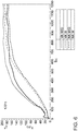
- FIG. 6 is shown by a measurement that the first lambda probe 14 and the second lambda probe 16 are brought by the inventive method faster to a temperature above the threshold temperature Ts. It can be seen in particular at the second lambda probe 16 that in the illustrated operating cycle of the internal combustion engine 10, the lambda probes 14, 16 can not be brought to a temperature above the temperature at the threshold value Ts without an increase in the heating power.
- the temperature of the first lambda probe 14 with or without additional heating measures is always higher than the temperature at the second lambda probe 16. Therefore, it may be useful in a method according to the invention only the heating power at the second lambda probe 16 downstream of the three-way catalyst 18th to increase.
Landscapes
- Engineering & Computer Science (AREA)
- Chemical & Material Sciences (AREA)
- General Engineering & Computer Science (AREA)
- Mechanical Engineering (AREA)
- Combustion & Propulsion (AREA)
- Health & Medical Sciences (AREA)
- Life Sciences & Earth Sciences (AREA)
- Chemical Kinetics & Catalysis (AREA)
- General Physics & Mathematics (AREA)
- Signal Processing (AREA)
- Biochemistry (AREA)
- Immunology (AREA)
- Pathology (AREA)
- Analytical Chemistry (AREA)
- Theoretical Computer Science (AREA)
- General Health & Medical Sciences (AREA)
- Physics & Mathematics (AREA)
- Electrochemistry (AREA)
- Molecular Biology (AREA)
- Exhaust Gas After Treatment (AREA)
- Combined Controls Of Internal Combustion Engines (AREA)
- Measuring Oxygen Concentration In Cells (AREA)
Abstract
Description
- Die Erfindung betrifft ein Verfahren zum Betreiben einer Lambdasonden-Anordnung an einem Abgaskanal eines Verbrennungsmotors.
- Abgassensoren können zur Kontrolle und zur Regelung einer Vielzahl von Parametern eines Verbrennungsmotors genutzt werden. Ein typisches Beispiel für einen solchen Abgassensor ist eine Lambdasonde, welche zur Regelung des Verbrennungsluftverhältnisses des Verbrennungsmotors genutzt wird, um eine möglichst effiziente Abgasnachbehandlung durch einen Drei-Wege-Katalysator zu ermöglichen.
- Bei einem Kaltstart oder in der Warmlaufphase des Verbrennungsmotors kann Feuchtigkeit abgasseitig in den Sondenkörper der Lambdasonde eindringen und sich dort niederschlagen. Dieses Wasser wird über mehrere Kaltstartvorgänge kumuliert, wenn eine bestimmte Schwellentemperatur im Kontaktbereich des Sondenkörpers der Lambdasonde mit der Sensorleitung nicht erreicht wird. Wenn sich hinreichend viel Wasser im Sondenkörper angesammelt hat, kann ein Kurzschluss über das Wasser entstehen, welcher zu einer Fehlfunktion der Lambdasonde führt. Durch den Kurzschluss kommt es zu einer erhöhten Sensorspannung, welche über die Diagnosefunktion des Steuergerätes erkannt wird und somit auf eine defekte Lambdasonde hindeutet. Da es sich hierbei meist um ein temporäres Fehlverhalten handelt, welches durch ein Ausbringen des Wassers aus dem Sondenkörper "geheilt" werden kann, kann ein Austausch der Lambdasonde vermieden werden, wenn nach gewissen Betriebsstunden eine Mindesttemperatur im Kontaktbereich zwischen Sondenkörper und Sensorleitung erreicht wird, bevor es zu einem Kurzschluss an der Lambdasonde kommt.
- Aus der
US 2014 0156172 A1 ist ein Verfahren bekannt, bei dem in Abhängigkeit von einem Taupunkt des Wasserdampfes im Abgaskanal die Leistung des Heizelements in einer Abgassonde angepasst wird, um einen Niederschlag von Wasser an der Spitze des Sensorelements der Lambdasonde zu kompensieren. - Aus der
US 2010 0300068 A1 ist ein Verfahren bekannt, bei dem die Temperatur der Wand des Abgaskanals anhand der gemessenen Abgastemperatur, des Volumenstroms des Abgases und der Umgebungstemperatur abgeschätzt wird. Dabei wird der Taupunkt an der Wand des Abgaskanals anhand der Luftmasse und des Verbrennungsluftverhältnisses abgeschätzt und daraus die Menge an Kondenswasser abgeschätzt, welche sich an der Wand des Abgaskanals niederschlägt. - Der Erfindung liegt nun die Aufgabe zugrunde, die Lambdasonde bei einem höheren Wassereintrag schneller aufzuheizen und ein höheres Temperaturniveau bei geringer Motorlast zu erreichen, um am Sondenkörper einen hinreichend großen Dampfdruck zu erzeugen, um das Wasser aus dem Sondenkörper auszutreiben und somit einen Kurzschluss und eine Fehlfunktion der Lambdasonde zu verhindern.
- Die Aufgabe wird durch ein erfindungsgemäßes Verfahren zum Betreiben einer Lambdasonden-Anordnung an einem Abgaskanal eines Verbrennungsmotors gelöst, welches folgende Schritte umfasst:
- Ermitteln eines Wassereintrages in eine im Abgaskanal des Verbrennungsmotors angeordnete Lambdasonde
- Ermitteln der Wassermenge, welche von der Lambdasonde an das Abgas im Abgaskanal abgegeben wird,
- Bilanzierung der Wassermenge, welche in der Lambdasonde verbleibt, und
- Abgleich der in der Lambdasonde vorhandenen Wassermenge mit einem maximal zulässigen Schwellenwert, wobei bei einem Überschreiten des maximal zulässigen Schwellenwertes die Heizleistung für die Lambdasonde erhöht wird, um das Wasser aus der Lambdasonde auszutreiben.
- Damit die Sonde schneller aufgeheizt und ein höheres Temperaturniveau bei niedriger Last erreicht wird, kann die Lambdasonde über die in der Lambdasonde vorhandene Heizung stärker beheizt werden, als es bei den gleichen Bedingungen und geringerem Wassereintrag geschehen würde. Da ein häufiges, starkes Heizen jedoch zu einer vorschnellen Alterung des Lambdasonde führen kann, liegt die erfindungsgemäße Lösung darin, den verstärkten Heizvorgang nur dann einzuleiten, wenn ein kritischer Schwellenwert für den Wassereintrag in den Sondenkörper der Lambdasonde überschritten ist, um dann die Lambdasonde zu "trocknen". Die Lambdasonden-Anordnung umfasst dabei mindestens eine im Abgaskanal angeordnete Lambdasonde sowie ein Steuergerät, über welches die Lambdasonde angesteuert werden kann.
- Durch die in den abhängigen Ansprüchen aufgeführten Merkmale sind vorteilhafte Weiterentwicklungen und Verbesserungen des erfindungsgemäßen Verfahrens zum Betrieb der Lambdasonden-Anordnung möglich.
- In bevorzugter Ausgestaltung der Erfindung ist vorgesehen, dass ein Wassermengenzähler vorgesehen ist, welcher den Wassereintrag in die Lambdasonde über mehrere Startvorgänge des Verbrennungsmotors aufsummiert, falls eine Schwellentemperatur zur Aktivierung des Wasseraustrags aus der Lambdasonde nicht erreicht wird. Da insbesondere ein häufiger Kurzstreckenverkehr mit vielen Kaltstartphasen zu einem kumuliert verstärkten Wassereintrag in die Lambdasonde führt, ist die Einrichtung eines Wassermengenzähler besonders vorteilhaft, um eine bedarfsgerechte Steuerung der Heizung der Lambdasonde zu ermöglichen.
- In weiterer bevorzugter Ausgestaltung der Erfindung ist vorgesehen, dass die Startvorgänge in Abhängigkeit von einer ermittelten Umgebungstemperatur mit einem Gewichtungsfaktor multipliziert werden. Somit können Startvorgänge, bei denen ein höherer abgasseitiger Wassereintrag in die Lambdasonde erwartet wird, stärker gewichtet werden als Startvorgänge, bei denen voraussichtlich weniger Wasserdampf in den Sondenkörper der Lambdasonde eindringt. Dadurch kann die Wassermenge im Sondenkörper genauer abgeschätzt werden, sodass die Erhöhung der Heizleistung entsprechend eingeleitet werden kann.
- In einer vorteilhaften Weiterbildung des Verfahrens ist vorgesehen, dass der Wassermengenzähler zurückgesetzt oder reduziert wird, wenn eine Schwellentemperatur an der Lambdasonde, insbesondere am Sondenkörper der Lambdasonde erreicht wird. Durch ein Zurücksetzen oder Reduzieren des Wassermengenzählers wird der Tatsache Rechnung getragen, dass ab einer gewissen Schwellentemperatur der Dampfdruck des in der Lambdasonde vorliegenden Wassers derart hoch ist, dass das Wasser, insbesondere in Form von Wasserdampf, aus der Lambdasonde in den Abgaskanal ausgetrieben wird.
- In einer weiteren Verbesserung des Verfahrens ist vorgesehen, dass die Schwellentemperatur an der Lambdasonde in einem Bereich von 160°C bis 220°C liegt. Besonders vorteilhaft hat sich hierbei ein Bereich von 175°C bis 190°C erwiesen, da hier zum einen ein hinreichend hoher Dampfdruck des Wasser vorherrscht, die Temperatur jedoch nicht so hoch ist, dass es zu einer vorzeitigen beziehungsweise beschleunigten Alterung der Lambdasonde kommt.
- Besonders bevorzugt ist dabei, wenn der Wassermengenzähler nur dann reduziert wird, wenn die Schwellentemperatur mindestens für ein definiertes Zeitintervall überschritten wird. Um eine Temperatur an den Bereichen der Lambdasonde sicherzustellen, an denen sich das Wasser ansammelt, ist es vorteilhaft, wenn die Schwellentemperatur nicht nur erreicht wird, sondern für mindestens einen definierten Zeitraum erreicht oder überschritten wird. Dadurch wird sichergestellt, dass sich alle Komponenten der Lambdasonde soweit aufheizen, dass der zum Austreiben des Wassers aus der Lambdasonde notwendige Dampfdruck erreicht wird. Zudem ist das Volumen, welches durch die Dichtungen der Lambdasonde in den Abgaskanal gefördert werden kann, begrenzt, sodass zu einer wesentlichen oder vollständigen Austreibung des Wassers aus der Lambdasonde ein definierter Zeitraum notwendig ist.
- Dabei ist mit weiterem Vorteil vorgesehen, dass die Reduzierung des Wertes des Wassermengenzählers in Abhängigkeit der Temperatur an der Lambdasonde erfolgt. Bei höherer Temperatur entstehen höhere Dampfdrücke in der Lambdasonde, sodass ein Austreiben von Wasser aus der Lambdasonde begünstigt wird. Durch eine temperaturabhängige Funktion zur Berechnung der aus der Lambdasonde an den Abgaskanal abgegebenen Wassermenge kann dies im Berechnungsmodell berücksichtigt werden, wodurch sich die Genauigkeit des Berechnungsmodells erhöht und die zusätzliche Heizleistung der Heizung der Lambdasonde früher als bei einer Berechnung ohne Einbeziehung der Temperatur erfolgen kann.
- In einer weiteren Verbesserung des Verfahrens ist vorgesehen, dass die Heizleistung für die Lambdasonde durch eine Erhöhung der Spannung an der Lambdasonde erfolgt. Durch eine Erhöhung der Spannung kann bei näherungsweise gleichem elektrischen Widerstand der Lambdasonde eine schnellere Erwärmung erreicht werden. Somit kann auf einfache Art und Weise die Sondentemperatur auf eine Temperatur oberhalb der Schwellentemperatur zum Austreiben von Wasser aus dem Sondenkörper der Lambdasonde erhöht werden.
- Weiterhin ist mit Vorteil vorgesehen, dass als zusätzliche Heizmaßnahme zur Erwärmung der Lambdasonde eine Verstellung des Zündwinkels des Verbrennungsmotors in Richtung "spät" erfolgt. Durch eine Zündwinkelverstellung in Richtung "spät" kann die Abgastemperatur des Verbrennungsmotors erhöht werden. Durch ein wärmeres Abgas des Verbrennungsmotors ist neben der Sondenheizung eine zusätzliche Erwärmung der Lambdasonde durch das Abgas möglich. Dieses Verfahren ist insbesondere geeignet, um eine Lambdasonde im Abgaskanal stromaufwärts des Drei-Wege-Katalysators über die Schwellentemperatur zu erwärmen.
- Alternativ oder zusätzlich ist es möglich, die Temperatur an der Lambdasonde zu erhöhen, in dem mindestens ein erster Zylinder des Verbrennungsmotors, vorzugsweise eine erste Gruppe von Zylindern des Verbrennungsmotors, mit einem unterstöchiometrischen Verbrennungsluftverhältnis und mindestens ein zweiter Zylinder des Verbrennungsmotors, vorzugsweise eine zweite Gruppe von Zylindern des Verbrennungsmotors, mit einem überstöchiometrischen Verbrennungsluftverhältnis betrieben werden, sodass sich im Abgaskanal stromaufwärts des Drei-Wege-Katalysators ein stöchiometrisches Abgas einstellt, wobei die unverbrannten Bestandteile des Kraftstoffs aus dem Zylinders oder den Zylindern mit unterstöchiometrischem Verbrennungsluftverhältnis mit dem Restsauerstoff aus dem Zylinder oder den Zylindern mit überstöchiometrischem Verbrennungsluftverhältnis im Abgaskanal, insbesondere an der Oberfläche des Katalysators, exotherm umgesetzt werden. Auf diese Weise ist insbesondere eine Aufheizung einer Lambdasonde stromabwärts des Drei-Wege-Katalysators möglich.
- Alternativ ist vorgesehen, dass der Verbrennungsmotor mit einem mageren, überstöchiometrischen Verbrennungsluftverhältnis betrieben wird und durch eine Nacheinspritzung Kraftstoff in der Brennraum eingebracht wird, welcher erst im Abgaskanal, insbesondere auf der Oberfläche des Katalysators umgesetzt wird. Auf diese Weise ist insbesondere eine Aufheizung einer Lambdasonde stromabwärts des Drei-Wege-Katalysators möglich.
- Erfindungsgemäß wird ferner eine Lambdasonden-Anordnung zur Regelung eines Drei-Wege-Katalysators in einem Abgaskanal eines Verbrennungsmotors vorgeschlagen, welche mindestens eine Lambdasonde, welche im Abgaskanal zur Regelung des Drei-Wege-Katalysators angeordnet ist, sowie ein Steuergerät umfasst, wobei das Steuergerät einen maschinenlesbaren Programmcode aufweist, welcher dazu eingerichtet ist, ein erfindungsgemäßes Verfahren durchzuführen.
- Weitere bevorzugte Ausgestaltungen der Erfindung ergeben sich aus den übrigen, in den Unteransprüchen genannten Merkmalen.
- Die verschiedenen in dieser Anmeldung genannten Ausführungsformen der Erfindung sind, sofern im Einzelfall nicht anders ausgeführt, mit Vorteil miteinander kombinierbar.
- Die Erfindung wird nachfolgend in Ausführungsbeispielen anhand der zugehörigen Zeichnungen erläutert. Es zeigen:
- Figur 1
- einen Verbrennungsmotor mit einem Abgaskanal sowie einem im Abgaskanal angeordneten Drei-Wege-Katalysator, welcher über Lambdasonden regelbar ist, zur Durchführung eines erfindungsgemäßen Verfahrens;
- Figur 2
- ein Ablaufdiagramm zum Wassereintrag in die Lambdasonde;
- Figur 3
- ein Diagramm zur Ermittlung eines Gewichtungsfaktors in Abhängigkeit von der Temperatur, um den Wassereintrag in Abhängigkeit der Abgastemperatur während des Starts/ in der Warmlaufphase zu bewerten;
- Figur 4
- ein Diagramm zum Wasseraustrag aus der Lambdasonde in Abhängigkeit von der Temperatur an der Sonde;
- Figur 5
- ein Diagramm zur Reduzierung des Wassermengenzählers in Abhängigkeit von der Temperatur;
- Figur 6
- einen tatsächlichen Temperaturverlauf an einem Sondenkörper einer Lambdasonde mit und ohne eine/r Erhöhung der Heizleistung durch das erfindungsgemäße Verfahren.
-
Figur 1 zeigt den einen Verbrennungsmotor 10 mit einem Abgaskanal 12. In dem Abgaskanal 12 ist ein Drei-Wege-Katalysator 18 zur Abgasnachbehandlung der Verbrennungsprodukte des Verbrennungsmotors 10 angeordnet. In Strömungsrichtung eines Abgases des Verbrennungsmotors 10 sind stromaufwärts des Drei-Wege-Katalysators 18 eine erste Lambdasonde 14 und stromabwärts des Drei-Wege-Katalysators 18 eine zweite Lambdasonde 16 angeordnet. Die Lambdasonden 14, 16 sind über Signalleitungen 20 mit einem Steuergerät 22 des Verbrennungsmotors 10 verbunden. Die Lambdasonden 14, 16 und das Steuergerät 22 bilden eine Lambdasonden-Anordnung 24, mit welcher ein erfindungsgemäßes Verfahren zur Ansteuerung der Lambdasonden 14, 16 ermöglicht werden kann. Die Lambdasonden 14, 16 ragen dabei in den Abgaskanal 12, sodass sie mit dem Abgas des Verbrennungsmotors 10 beaufschlagt werden. Da eine hermetische Abdichtung quasi unmöglich ist, kann unter bestimmten Rahmenbedingungen trotz Dichtelementen an den Lambdasonden 14, 16 eine Restmenge an Abgas in eine der Lambdasonden 14, 16 eindringen beziehungsweise aus der Lambdasonde in den Abgaskanal 12 gelangen. In dem Steuergerät 22 ist softwaretechnisch ein Wassermengen-Zähler WZ implementiert, mit dem die Wassermenge in den Lambdasonden 14, 16 ermittelt wird. - In den
Figuren 2 bis 5 ist der Ablauf eines erfindungsgemäßen Verfahrens zum Betreiben einer Lambdasonden-Anordnung 24 an einem Abgaskanal 12 eines Verbrennungsmotors 10 dargestellt. In einem ersten Schritt des Verfahrens erfolgt mittels einer Software des Steuergeräts 22 eine Ermittlung der Wassermenge, die in die Lambdasonden strömt. Da die Lambdasonde 16 stromab des Drei-Wege-Katalysators 18 thermisch niedriger belastet ist, kann es insbesondere an dieser zweiten Lambdasonde 16 zu einem Eindringen von Wasser und/oder Wasserdampf kommen. Zur Ermittlung der Wassermenge ist ein physikalisches Integrationsmodell möglich, aber auch ein äquivalenter Faktor, welcher empirisch für verschiedene Starttemperaturen bei einem Kaltstart des Verbrennungsmotors 10 ermittelt wird. InFigur 2 ist die Aufsummierung der Wassermenge WZ über mehrere Kaltstartvorgänge n dargestellt, wenn zwischenzeitlich nicht eine Schwellentemperatur Ts erreicht wird, ab welcher der Dampfdruck in der Lambdasonde 14, 16 derart hoch ist, dass der Wasserdampf in den Abgaskanal 12 ausgetrieben wird. Entscheidende Einflüsse für die Wassermenge, die in die Lambdasonde 14, 16 eingetragen beziehungsweise ausgetragen wird, sind die Starttemperaturen sowie die Abgas- beziehungsweise Sondentemperaturen TL der Lambdasonde 14, 16. Die Abhängigkeit der Wassermenge von der Starttemperatur bei zwei aufeinanderfolgenden Kaltstarts ist inFigur 3 dargestellt. Dabei erfolgt der erste Kaltstart bei einer Temperatur T1 und der zweite Kaltstart bei einer Temperatur T2, wobei die Temperatur T1 größer als die Temperatur T2 ist. InFigur 2 ist ferner zu erkennen, dass ab einer gewissen Anzahl n von Kaltstarts ohne zwischengeschaltete Regeneration der Wassermengenzähler WZ einen kritischen Schwellenwert TW erreicht, ab dem zusätzlich Maßnahmen zum Austreiben von Wasser aus der Lambdasonde 14, 16 notwendig sind. - In
Figur 4 ist eine Reduzierung des Wassermengen-Zählers WZ in Abhängigkeit der Temperatur TL an der Lambdasonde 14, 16 sowie der Zeit t dargestellt. Erreicht die Temperatur TL an der Lambdasonde 14, 16 für ein definiertes Zeitintervall Δt eine Temperatur oberhalb der Schwellentemperatur Ts, strömt Wasser in Form von Wasserdampf zurück in das Abgas des Verbrennungsmotors 10. Die aus der Lambdasonde 14, 16 ausgetriebene Wassermenge wird in einem zweiten Verfahrensschritt ebenfalls über ein physikalisches Gleichgewicht oder äquivalent bestimmt. In einem dritten Verfahrensschritt wird die Wassermenge bilanziert, sodass anschließend in einem vierten Schritt ein Abgleich der in der Lambdasonde 14, 16 befindlichen Wassermenge mit einer maximal zulässigen, kritischen Wassermenge in der Lambdasonde 14, 16 vollzogen werden kann. Ist diese kritische Wassermenge überschritten, was durch einen Schwellenwert Tw des Wassermengen-Zählers erkannt werden kann, wird die Heizungsregelung für eine Sondenheizung der Lambdasonde 14, 16 auf einen höheren Sollwert eingestellt. Die Dauer und die Höhe dieser Sollwerterhöhung der Heizungsregelung sind abhängig von der Alterung, der maximal zulässigen Bauteiltemperatur und vom Diffusionsverhalten der Lambdasonde 14, 16. Entscheidend für einen Wasseraustrag aus der Lambdasonde 14, 16 ist wie inFigur 5 dargestellt die Temperatur TL im Kontaktierungsbereich zwischen dem Sondenkörper der Lambdasonde 14, 16 und der Signalleitung 20. In Abhängigkeit der Temperatur oberhalb der Schwellentemperatur Ts wird das Bilanzmodell unterschiedlich schnell angepasst bzw. der äquivalente Faktor unterschiedlich schnell reduziert. - In
Figur 6 ist anhand einer Messung dargestellt, dass die erste Lambdasonde 14 sowie die zweite Lambdasonde 16 durch das erfindungsgemäße Verfahren schneller auf eine Temperatur oberhalb der Schwellentemperatur Ts gebracht werden. Dabei zeigt sich insbesondere an der zweiten Lambdasonde 16, dass bei dem dargestellten Betriebszyklus des Verbrennungsmotors 10 die Lambdasonden 14, 16 ohne eine Erhöhung der Heizleistung nicht auf eine Temperatur oberhalb der Temperatur am Schwellenwert Ts gebracht werden können. Dabei ist die Temperatur der ersten Lambdasonde 14 mit oder ohne zusätzliche Heizmaßnahmen stets höher als die Temperatur an der zweiten Lambdasonde 16. Daher kann es sinnvoll sein, bei einem erfindungsgemäßen Verfahren ausschließlich die Heizleistung an der zweiten Lambdasonde 16 stromab des Drei-Wege-Katalysators 18 zu erhöhen. -
- 10
- Verbrennungsmotor
- 12
- Abgaskanal
- 14
- (erste) Lambdasonde
- 16
- (zweite) Lambdasonde
- 18
- Drei-Wege-Katalysator
- 20
- Signalleitung
- 22
- Steuergerät
- 24
- Lambdasonden-Anordnung
- k
- Gewichtungsfakor
- KS
- Kaltstart
- n
- Anzahl der Kaltstarts
- T
- Temperatur
- TL
- Temperatur Lambdasonde
- Ts
- Schwellenwert-Temperatur
- Tw
- Schwellenwert Wassermenge
- WZ
- Wassermengen-Zähler
- Δt
- Zeitintervall
Claims (10)
- Verfahren zum Betreiben einer Lambdasonden-Anordnung (24) an einem Abgaskanal (12) eines Verbrennungsmotors (10), umfassend folgende Schritte:- Ermitteln eines Wassereintrags in eine im Abgaskanal (12) eines Verbrennungsmotors (10) angeordnete Lambdasonde (14, 16),- Ermitteln einer Wassermenge, welche von der Lambdasonde (14, 16) an das Abgas im Abgaskanal (12) abgegeben wird,- Bilanzierung der Wassermenge, welche in der Lambdasonde (14, 16) verbleibt, und- Abgleich der in der Lambdasonde (14, 16) vorhandenen Wassermenge mit einem maximal zulässigen Schwellenwert (Tw), wobei bei Überschreiten des maximal zulässigen Schwellenwertes (Tw) die Heizleistung für die Lambdasonde (14, 16) erhöht wird, um das Wasser aus der Lambdasonde (14, 16) auszutreiben.
- Verfahren nach Anspruch 1, dadurch gekennzeichnet, dass ein Wassermengenzähler (WZ) vorgesehen ist, welcher den Wassereintrag in die Lambdasonde (14, 16) über mehrere Startvorgänge des Verbrennungsmotors (10) aufsummiert, falls eine Schwellentemperatur (Ts) zur Aktivierung eines Wasseraustrags aus der Lambdasonde (14, 16) nicht erreicht wird.
- Verfahren nach Anspruch 2, dadurch gekennzeichnet, dass die Startvorgänge in Abhängigkeit von einer ermittelten Umgebungstemperatur (T) mit einem Gewichtungsfaktor (k) multipliziert werden.
- Verfahren nach Anspruch 2 oder 3, dadurch gekennzeichnet, dass der Wert des Wassermengenzählers (WZ) zurückgesetzt oder reduziert wird, wenn eine Schwellentemperatur (Ts) an der Lambdasonde (14, 16) erreicht wird.
- Verfahren nach Anspruch 4, dadurch gekennzeichnet, dass der Wassermengenzähler (WZ) nur dann reduziert wird, wenn die Schwellentemperatur (Ts) für mindestens ein definiertes Zeitintervall (Δt) überschritten wird.
- Verfahren nach Anspruch 5, dadurch gekennzeichnet, dass die Reduzierung des Wassermengenzählers (WZ) in Abhängigkeit der Temperatur (TL) an der Lambdasonde erfolgt.
- Verfahren nach einem der Ansprüche 1 bis 6, dadurch gekennzeichnet, dass die Heizleistung für die Lambdasonde (14, 16) durch ein Erhöhung der Spannung (ΔU) an der Lambdasonde (14, 16) erfolgt.
- Verfahren nach einem der Ansprüche 1 bis 7, dadurch gekennzeichnet, dass als zusätzliche Heizmaßnahme eine Verstellung des Zündwinkels des Verbrennungsmotors (10) in Richtung "spät" erfolgt.
- Verfahren nach einem der Ansprüche 1 bis 8, dadurch gekennzeichnet, dass als zusätzliche Heißmaßnahme ein erster Zylinder oder eine erste Gruppe von Zylinders des Verbrennungsmotors (10) mit einem unterstöchiometrischen Verbrennungsluftverhältnis (A < 1) und ein zweiter Zylinder oder eine zweite Gruppe von Zylindern mit einem überstöchiometrischen Verbrennungsluftverhältnis (A > 1) betrieben werden, wobei sich im Abgaskanal (12) stromaufwärts des Drei-Wege-Katalysators (18) ein stöchiometrisches Abgas einstellt, oder
der Verbrennungsmotor (10) mit einem mageren, überstöchiometrischen Verbrennungsluftverhältnis (A > 1) betrieben wird und durch eine Nacheinspritzung in zumindest einen der Zylinder des Verbrennungsmotors (10) so viel Kraftstoff eindosiert wird, dass sich im Abgaskanal (12) stromaufwärts des Drei-Wege-Katalysators (18) ein stöchiometrisches Abgas einstellt. - Lambdasonden-Anordnung (24) zur Regelung eines Drei-Wege-Katalysators (18) in einem Abgaskanal (12) eines Verbrennungsmotors (10), umfassend mindestens eine Lambdasonde (14, 16), welche im Abgaskanal (12) zur Regelung des Drei-Wege-Katalysators (18) angeordnet ist, sowie ein Steuergerät (22) mit einem maschinenlesbaren Programmcode, welcher dazu eingerichtet ist, ein Verfahren nach einem der Ansprüche 1 bis 9 durchzuführen.
Applications Claiming Priority (1)
| Application Number | Priority Date | Filing Date | Title |
|---|---|---|---|
| DE102016115247.1A DE102016115247A1 (de) | 2016-08-17 | 2016-08-17 | Verfahren und Vorrichtung zum Betreiben einer Lambdasonden-Anordnung an einem Abgaskanal eines Verbrennungsmotors |
Publications (2)
| Publication Number | Publication Date |
|---|---|
| EP3284936A1 true EP3284936A1 (de) | 2018-02-21 |
| EP3284936B1 EP3284936B1 (de) | 2019-10-09 |
Family
ID=59569189
Family Applications (1)
| Application Number | Title | Priority Date | Filing Date |
|---|---|---|---|
| EP17185257.7A Active EP3284936B1 (de) | 2016-08-17 | 2017-08-08 | Verfahren und vorrichtung zum betreiben einer lambdasonden-anordnung in einem abgaskanal eines verbrennungsmotors |
Country Status (3)
| Country | Link |
|---|---|
| EP (1) | EP3284936B1 (de) |
| CN (1) | CN107762599B (de) |
| DE (1) | DE102016115247A1 (de) |
Families Citing this family (2)
| Publication number | Priority date | Publication date | Assignee | Title |
|---|---|---|---|---|
| JP6658573B2 (ja) | 2017-01-26 | 2020-03-04 | トヨタ自動車株式会社 | 内燃機関の制御装置 |
| CN112983609B (zh) * | 2021-03-26 | 2022-08-05 | 潍柴动力股份有限公司 | 一种温度控制方法 |
Citations (4)
| Publication number | Priority date | Publication date | Assignee | Title |
|---|---|---|---|---|
| US20070271904A1 (en) * | 2006-04-06 | 2007-11-29 | Denso Corporation | System for controlling exhaust gas sensor having heater |
| US20100300068A1 (en) * | 2008-03-13 | 2010-12-02 | Toyota Jidosha Kabushiki Kaisha | Exhaust gas sensor control system and control method |
| US20140156172A1 (en) * | 2012-12-05 | 2014-06-05 | Ford Global Technologies, Llc | Exhaust humidity sensor |
| DE102013223429A1 (de) * | 2013-11-18 | 2015-05-21 | Robert Bosch Gmbh | Verfahren und Vorrichtung zur Erkennung einer Wasserdurchfahrt mittels Abgassensoren |
Family Cites Families (4)
| Publication number | Priority date | Publication date | Assignee | Title |
|---|---|---|---|---|
| JP5223734B2 (ja) * | 2009-03-10 | 2013-06-26 | トヨタ自動車株式会社 | ヒータ付センサのヒータ制御装置 |
| DE102009001660A1 (de) * | 2009-03-19 | 2010-09-23 | Robert Bosch Gmbh | Sensoranordnung mit verringerter Kurzschlussanfälligkeit |
| US8857155B2 (en) * | 2013-01-18 | 2014-10-14 | Ford Global Technologies, Llc | Methods and systems for humidity detection via an exhaust gas sensor |
| US9719448B2 (en) * | 2013-09-13 | 2017-08-01 | Ford Global Technologies, Llc | Methods and systems for adjusting heater power of an oxygen sensor to reduce degradation from water |
-
2016
- 2016-08-17 DE DE102016115247.1A patent/DE102016115247A1/de not_active Withdrawn
-
2017
- 2017-08-08 EP EP17185257.7A patent/EP3284936B1/de active Active
- 2017-08-11 CN CN201710685003.7A patent/CN107762599B/zh active Active
Patent Citations (4)
| Publication number | Priority date | Publication date | Assignee | Title |
|---|---|---|---|---|
| US20070271904A1 (en) * | 2006-04-06 | 2007-11-29 | Denso Corporation | System for controlling exhaust gas sensor having heater |
| US20100300068A1 (en) * | 2008-03-13 | 2010-12-02 | Toyota Jidosha Kabushiki Kaisha | Exhaust gas sensor control system and control method |
| US20140156172A1 (en) * | 2012-12-05 | 2014-06-05 | Ford Global Technologies, Llc | Exhaust humidity sensor |
| DE102013223429A1 (de) * | 2013-11-18 | 2015-05-21 | Robert Bosch Gmbh | Verfahren und Vorrichtung zur Erkennung einer Wasserdurchfahrt mittels Abgassensoren |
Also Published As
| Publication number | Publication date |
|---|---|
| EP3284936B1 (de) | 2019-10-09 |
| CN107762599A (zh) | 2018-03-06 |
| DE102016115247A1 (de) | 2018-02-22 |
| CN107762599B (zh) | 2020-03-03 |
Similar Documents
| Publication | Publication Date | Title |
|---|---|---|
| EP2260195B1 (de) | Verfahren zum betreiben einer lambdasonde während der aufwärmphase | |
| DE102005004619B4 (de) | Abgasemissionssteuersystem für einen Verbrennungsmotor und Abgasemissionssteuerverfahren | |
| WO2011124283A1 (de) | Verfahren zum heizen eines katalysators in einem motorsystem und zur diagnose der wirksamkeit von massnahmen zum heizen des katalysators | |
| EP1454049B1 (de) | Verfahren, computerprogramm, sowie steuer- und/oder regelgerät zum betreiben einer brennkraftmaschine | |
| DE19749817A1 (de) | Vorrichtung und Verfahren zur Ermittlung des Spritzbeginns oder der Verbrennungslage | |
| DE10143502C1 (de) | Verfahren und Vorrichtung zum Ansteuern piezobetriebener Kraftstoff-Einspritzventile | |
| DE112007000297B4 (de) | Betriebssteuerungsverfahren auf der Grundlage eines Ionenstroms in einer Verbrennungskraftmaschine | |
| DE102008005110A1 (de) | Verfahren und Steuerung zum Betreiben und Einstellen einer Lambda-Sonde | |
| DE102007000392A1 (de) | Verbrennungsmotor-Steuervorrichtung | |
| EP0991853A1 (de) | Verfahren zur überwachung der konvertierungsrate eines abgaskatalysators für eine brennkraftmaschine | |
| EP3284936B1 (de) | Verfahren und vorrichtung zum betreiben einer lambdasonden-anordnung in einem abgaskanal eines verbrennungsmotors | |
| DE4433632A1 (de) | Verfahren zur Überwachung einer Heizeinrichtung eines im Abgassystem einer Brennkraftmaschine angebrachten Sensors | |
| DE102004031083B3 (de) | Verfahren zur Beheizung von Lambdasonden in einer einer Brennkraftmaschine eines Fahrzeugs nachgeschalteten Abgasanlage | |
| WO2017097615A1 (de) | Verfahren zum betreiben einer brennkraftmaschine | |
| DE102011121099B4 (de) | Verfahren zum Betreiben einer Abgasreinigungseinrichtung sowie entsprechende Abgasreinigunseinrichtung | |
| WO2015185414A1 (de) | Verfahren zur korrektur einer spannungs-lambda-kennlinie | |
| EP1731746B1 (de) | Verfahren und Vorrichtung zur Überwachung der Funktionstüchtigkeit einer Ventilhub-Verstelleinrichtung einer Brennkraftmaschine in einer Kaltstartphase | |
| DE102007009105B4 (de) | Verfahren zur Motorsteuerung eines Dieselmotors und Motorsteuersystem | |
| EP3224464B1 (de) | Verfahren zur erkennung eines spannungsoffsets zumindest in einem bereich bei einer spannungs-lambda-kennlinie | |
| DE102011006170B4 (de) | Verfahren zum Betreiben der Lambdaregelung einer Brennkraftmaschine | |
| DE102007042227A1 (de) | Verfahren zur Bestimmung einer Abgastemperatur einer Brennkraftmaschine | |
| EP1444425B1 (de) | Verfahren zur steuerung der sekundärluftmenge | |
| EP2823171A1 (de) | Verfahren zur steuerung einer heizeinrichtung zur beheizung eines bauteils, steuervorrichtung sowie kraftfahrzeug mit einer solchen | |
| DE102006053805B4 (de) | Verfahren zum Betreiben einer Brennkraftmaschine zur Ermittlung einer in einem Brennraum befindlichen Füllung | |
| DE4437655C2 (de) | Verfahren zur Überwachung der Funktionsfähigkeit einer Katalysatorheizvorrichtung |
Legal Events
| Date | Code | Title | Description |
|---|---|---|---|
| PUAI | Public reference made under article 153(3) epc to a published international application that has entered the european phase |
Free format text: ORIGINAL CODE: 0009012 |
|
| STAA | Information on the status of an ep patent application or granted ep patent |
Free format text: STATUS: THE APPLICATION HAS BEEN PUBLISHED |
|
| AK | Designated contracting states |
Kind code of ref document: A1 Designated state(s): AL AT BE BG CH CY CZ DE DK EE ES FI FR GB GR HR HU IE IS IT LI LT LU LV MC MK MT NL NO PL PT RO RS SE SI SK SM TR |
|
| AX | Request for extension of the european patent |
Extension state: BA ME |
|
| STAA | Information on the status of an ep patent application or granted ep patent |
Free format text: STATUS: REQUEST FOR EXAMINATION WAS MADE |
|
| 17P | Request for examination filed |
Effective date: 20180821 |
|
| RBV | Designated contracting states (corrected) |
Designated state(s): AL AT BE BG CH CY CZ DE DK EE ES FI FR GB GR HR HU IE IS IT LI LT LU LV MC MK MT NL NO PL PT RO RS SE SI SK SM TR |
|
| GRAP | Despatch of communication of intention to grant a patent |
Free format text: ORIGINAL CODE: EPIDOSNIGR1 |
|
| STAA | Information on the status of an ep patent application or granted ep patent |
Free format text: STATUS: GRANT OF PATENT IS INTENDED |
|
| INTG | Intention to grant announced |
Effective date: 20190326 |
|
| GRAS | Grant fee paid |
Free format text: ORIGINAL CODE: EPIDOSNIGR3 |
|
| GRAA | (expected) grant |
Free format text: ORIGINAL CODE: 0009210 |
|
| STAA | Information on the status of an ep patent application or granted ep patent |
Free format text: STATUS: THE PATENT HAS BEEN GRANTED |
|
| AK | Designated contracting states |
Kind code of ref document: B1 Designated state(s): AL AT BE BG CH CY CZ DE DK EE ES FI FR GB GR HR HU IE IS IT LI LT LU LV MC MK MT NL NO PL PT RO RS SE SI SK SM TR |
|
| REG | Reference to a national code |
Ref country code: GB Ref legal event code: FG4D Free format text: NOT ENGLISH |
|
| REG | Reference to a national code |
Ref country code: CH Ref legal event code: EP |
|
| REG | Reference to a national code |
Ref country code: IE Ref legal event code: FG4D Free format text: LANGUAGE OF EP DOCUMENT: GERMAN |
|
| REG | Reference to a national code |
Ref country code: DE Ref legal event code: R096 Ref document number: 502017002504 Country of ref document: DE |
|
| REG | Reference to a national code |
Ref country code: AT Ref legal event code: REF Ref document number: 1189101 Country of ref document: AT Kind code of ref document: T Effective date: 20191115 |
|
| REG | Reference to a national code |
Ref country code: NL Ref legal event code: MP Effective date: 20191009 |
|
| REG | Reference to a national code |
Ref country code: LT Ref legal event code: MG4D |
|
| PG25 | Lapsed in a contracting state [announced via postgrant information from national office to epo] |
Ref country code: LT Free format text: LAPSE BECAUSE OF FAILURE TO SUBMIT A TRANSLATION OF THE DESCRIPTION OR TO PAY THE FEE WITHIN THE PRESCRIBED TIME-LIMIT Effective date: 20191009 Ref country code: BG Free format text: LAPSE BECAUSE OF FAILURE TO SUBMIT A TRANSLATION OF THE DESCRIPTION OR TO PAY THE FEE WITHIN THE PRESCRIBED TIME-LIMIT Effective date: 20200109 Ref country code: FI Free format text: LAPSE BECAUSE OF FAILURE TO SUBMIT A TRANSLATION OF THE DESCRIPTION OR TO PAY THE FEE WITHIN THE PRESCRIBED TIME-LIMIT Effective date: 20191009 Ref country code: NL Free format text: LAPSE BECAUSE OF FAILURE TO SUBMIT A TRANSLATION OF THE DESCRIPTION OR TO PAY THE FEE WITHIN THE PRESCRIBED TIME-LIMIT Effective date: 20191009 Ref country code: GR Free format text: LAPSE BECAUSE OF FAILURE TO SUBMIT A TRANSLATION OF THE DESCRIPTION OR TO PAY THE FEE WITHIN THE PRESCRIBED TIME-LIMIT Effective date: 20200110 Ref country code: ES Free format text: LAPSE BECAUSE OF FAILURE TO SUBMIT A TRANSLATION OF THE DESCRIPTION OR TO PAY THE FEE WITHIN THE PRESCRIBED TIME-LIMIT Effective date: 20191009 Ref country code: PT Free format text: LAPSE BECAUSE OF FAILURE TO SUBMIT A TRANSLATION OF THE DESCRIPTION OR TO PAY THE FEE WITHIN THE PRESCRIBED TIME-LIMIT Effective date: 20200210 Ref country code: SE Free format text: LAPSE BECAUSE OF FAILURE TO SUBMIT A TRANSLATION OF THE DESCRIPTION OR TO PAY THE FEE WITHIN THE PRESCRIBED TIME-LIMIT Effective date: 20191009 Ref country code: LV Free format text: LAPSE BECAUSE OF FAILURE TO SUBMIT A TRANSLATION OF THE DESCRIPTION OR TO PAY THE FEE WITHIN THE PRESCRIBED TIME-LIMIT Effective date: 20191009 Ref country code: PL Free format text: LAPSE BECAUSE OF FAILURE TO SUBMIT A TRANSLATION OF THE DESCRIPTION OR TO PAY THE FEE WITHIN THE PRESCRIBED TIME-LIMIT Effective date: 20191009 Ref country code: NO Free format text: LAPSE BECAUSE OF FAILURE TO SUBMIT A TRANSLATION OF THE DESCRIPTION OR TO PAY THE FEE WITHIN THE PRESCRIBED TIME-LIMIT Effective date: 20200109 |
|
| PG25 | Lapsed in a contracting state [announced via postgrant information from national office to epo] |
Ref country code: IS Free format text: LAPSE BECAUSE OF FAILURE TO SUBMIT A TRANSLATION OF THE DESCRIPTION OR TO PAY THE FEE WITHIN THE PRESCRIBED TIME-LIMIT Effective date: 20200224 Ref country code: HR Free format text: LAPSE BECAUSE OF FAILURE TO SUBMIT A TRANSLATION OF THE DESCRIPTION OR TO PAY THE FEE WITHIN THE PRESCRIBED TIME-LIMIT Effective date: 20191009 Ref country code: RS Free format text: LAPSE BECAUSE OF FAILURE TO SUBMIT A TRANSLATION OF THE DESCRIPTION OR TO PAY THE FEE WITHIN THE PRESCRIBED TIME-LIMIT Effective date: 20191009 |
|
| PG25 | Lapsed in a contracting state [announced via postgrant information from national office to epo] |
Ref country code: AL Free format text: LAPSE BECAUSE OF FAILURE TO SUBMIT A TRANSLATION OF THE DESCRIPTION OR TO PAY THE FEE WITHIN THE PRESCRIBED TIME-LIMIT Effective date: 20191009 |
|
| REG | Reference to a national code |
Ref country code: DE Ref legal event code: R097 Ref document number: 502017002504 Country of ref document: DE |
|
| PG2D | Information on lapse in contracting state deleted |
Ref country code: IS |
|
| PG25 | Lapsed in a contracting state [announced via postgrant information from national office to epo] |
Ref country code: CZ Free format text: LAPSE BECAUSE OF FAILURE TO SUBMIT A TRANSLATION OF THE DESCRIPTION OR TO PAY THE FEE WITHIN THE PRESCRIBED TIME-LIMIT Effective date: 20191009 Ref country code: RO Free format text: LAPSE BECAUSE OF FAILURE TO SUBMIT A TRANSLATION OF THE DESCRIPTION OR TO PAY THE FEE WITHIN THE PRESCRIBED TIME-LIMIT Effective date: 20191009 Ref country code: EE Free format text: LAPSE BECAUSE OF FAILURE TO SUBMIT A TRANSLATION OF THE DESCRIPTION OR TO PAY THE FEE WITHIN THE PRESCRIBED TIME-LIMIT Effective date: 20191009 Ref country code: DK Free format text: LAPSE BECAUSE OF FAILURE TO SUBMIT A TRANSLATION OF THE DESCRIPTION OR TO PAY THE FEE WITHIN THE PRESCRIBED TIME-LIMIT Effective date: 20191009 Ref country code: IS Free format text: LAPSE BECAUSE OF FAILURE TO SUBMIT A TRANSLATION OF THE DESCRIPTION OR TO PAY THE FEE WITHIN THE PRESCRIBED TIME-LIMIT Effective date: 20200209 |
|
| PLBE | No opposition filed within time limit |
Free format text: ORIGINAL CODE: 0009261 |
|
| STAA | Information on the status of an ep patent application or granted ep patent |
Free format text: STATUS: NO OPPOSITION FILED WITHIN TIME LIMIT |
|
| PG25 | Lapsed in a contracting state [announced via postgrant information from national office to epo] |
Ref country code: SM Free format text: LAPSE BECAUSE OF FAILURE TO SUBMIT A TRANSLATION OF THE DESCRIPTION OR TO PAY THE FEE WITHIN THE PRESCRIBED TIME-LIMIT Effective date: 20191009 Ref country code: SK Free format text: LAPSE BECAUSE OF FAILURE TO SUBMIT A TRANSLATION OF THE DESCRIPTION OR TO PAY THE FEE WITHIN THE PRESCRIBED TIME-LIMIT Effective date: 20191009 Ref country code: IT Free format text: LAPSE BECAUSE OF FAILURE TO SUBMIT A TRANSLATION OF THE DESCRIPTION OR TO PAY THE FEE WITHIN THE PRESCRIBED TIME-LIMIT Effective date: 20191009 |
|
| 26N | No opposition filed |
Effective date: 20200710 |
|
| REG | Reference to a national code |
Ref country code: DE Ref legal event code: R082 Ref document number: 502017002504 Country of ref document: DE |
|
| PG25 | Lapsed in a contracting state [announced via postgrant information from national office to epo] |
Ref country code: SI Free format text: LAPSE BECAUSE OF FAILURE TO SUBMIT A TRANSLATION OF THE DESCRIPTION OR TO PAY THE FEE WITHIN THE PRESCRIBED TIME-LIMIT Effective date: 20191009 |
|
| PG25 | Lapsed in a contracting state [announced via postgrant information from national office to epo] |
Ref country code: MC Free format text: LAPSE BECAUSE OF FAILURE TO SUBMIT A TRANSLATION OF THE DESCRIPTION OR TO PAY THE FEE WITHIN THE PRESCRIBED TIME-LIMIT Effective date: 20191009 |
|
| REG | Reference to a national code |
Ref country code: CH Ref legal event code: PL |
|
| PG25 | Lapsed in a contracting state [announced via postgrant information from national office to epo] |
Ref country code: LI Free format text: LAPSE BECAUSE OF NON-PAYMENT OF DUE FEES Effective date: 20200831 Ref country code: LU Free format text: LAPSE BECAUSE OF NON-PAYMENT OF DUE FEES Effective date: 20200808 Ref country code: CH Free format text: LAPSE BECAUSE OF NON-PAYMENT OF DUE FEES Effective date: 20200831 |
|
| REG | Reference to a national code |
Ref country code: BE Ref legal event code: MM Effective date: 20200831 |
|
| PG25 | Lapsed in a contracting state [announced via postgrant information from national office to epo] |
Ref country code: BE Free format text: LAPSE BECAUSE OF NON-PAYMENT OF DUE FEES Effective date: 20200831 Ref country code: IE Free format text: LAPSE BECAUSE OF NON-PAYMENT OF DUE FEES Effective date: 20200808 |
|
| PG25 | Lapsed in a contracting state [announced via postgrant information from national office to epo] |
Ref country code: TR Free format text: LAPSE BECAUSE OF FAILURE TO SUBMIT A TRANSLATION OF THE DESCRIPTION OR TO PAY THE FEE WITHIN THE PRESCRIBED TIME-LIMIT Effective date: 20191009 Ref country code: MT Free format text: LAPSE BECAUSE OF FAILURE TO SUBMIT A TRANSLATION OF THE DESCRIPTION OR TO PAY THE FEE WITHIN THE PRESCRIBED TIME-LIMIT Effective date: 20191009 Ref country code: CY Free format text: LAPSE BECAUSE OF FAILURE TO SUBMIT A TRANSLATION OF THE DESCRIPTION OR TO PAY THE FEE WITHIN THE PRESCRIBED TIME-LIMIT Effective date: 20191009 |
|
| PG25 | Lapsed in a contracting state [announced via postgrant information from national office to epo] |
Ref country code: MK Free format text: LAPSE BECAUSE OF FAILURE TO SUBMIT A TRANSLATION OF THE DESCRIPTION OR TO PAY THE FEE WITHIN THE PRESCRIBED TIME-LIMIT Effective date: 20191009 |
|
| P01 | Opt-out of the competence of the unified patent court (upc) registered |
Effective date: 20230523 |
|
| REG | Reference to a national code |
Ref country code: AT Ref legal event code: MM01 Ref document number: 1189101 Country of ref document: AT Kind code of ref document: T Effective date: 20220808 |
|
| PG25 | Lapsed in a contracting state [announced via postgrant information from national office to epo] |
Ref country code: AT Free format text: LAPSE BECAUSE OF NON-PAYMENT OF DUE FEES Effective date: 20220808 |
|
| PGFP | Annual fee paid to national office [announced via postgrant information from national office to epo] |
Ref country code: GB Payment date: 20240827 Year of fee payment: 8 |
|
| PGFP | Annual fee paid to national office [announced via postgrant information from national office to epo] |
Ref country code: FR Payment date: 20240826 Year of fee payment: 8 |
|
| PGFP | Annual fee paid to national office [announced via postgrant information from national office to epo] |
Ref country code: DE Payment date: 20250831 Year of fee payment: 9 |
|
| GBPC | Gb: european patent ceased through non-payment of renewal fee |
Effective date: 20250808 |