EP3282958B1 - Vorrichtung zur perkutanen transpedikulären fusion - Google Patents
Vorrichtung zur perkutanen transpedikulären fusion Download PDFInfo
- Publication number
- EP3282958B1 EP3282958B1 EP16727744.1A EP16727744A EP3282958B1 EP 3282958 B1 EP3282958 B1 EP 3282958B1 EP 16727744 A EP16727744 A EP 16727744A EP 3282958 B1 EP3282958 B1 EP 3282958B1
- Authority
- EP
- European Patent Office
- Prior art keywords
- vertebra
- injection
- cannulated
- graft
- vertèbre
- Prior art date
- Legal status (The legal status is an assumption and is not a legal conclusion. Google has not performed a legal analysis and makes no representation as to the accuracy of the status listed.)
- Active
Links
Images







Classifications
-
- A—HUMAN NECESSITIES
- A61—MEDICAL OR VETERINARY SCIENCE; HYGIENE
- A61B—DIAGNOSIS; SURGERY; IDENTIFICATION
- A61B17/00—Surgical instruments, devices or methods
- A61B17/16—Instruments for performing osteoclasis; Drills or chisels for bones; Trepans
- A61B17/17—Guides or aligning means for drills, mills, pins or wires
- A61B17/1739—Guides or aligning means for drills, mills, pins or wires specially adapted for particular parts of the body
- A61B17/1757—Guides or aligning means for drills, mills, pins or wires specially adapted for particular parts of the body for the spine
-
- A—HUMAN NECESSITIES
- A61—MEDICAL OR VETERINARY SCIENCE; HYGIENE
- A61B—DIAGNOSIS; SURGERY; IDENTIFICATION
- A61B17/00—Surgical instruments, devices or methods
- A61B17/16—Instruments for performing osteoclasis; Drills or chisels for bones; Trepans
- A61B17/1637—Hollow drills or saws producing a curved cut, e.g. cylindrical
-
- A—HUMAN NECESSITIES
- A61—MEDICAL OR VETERINARY SCIENCE; HYGIENE
- A61B—DIAGNOSIS; SURGERY; IDENTIFICATION
- A61B17/00—Surgical instruments, devices or methods
- A61B17/16—Instruments for performing osteoclasis; Drills or chisels for bones; Trepans
- A61B17/1662—Instruments for performing osteoclasis; Drills or chisels for bones; Trepans for particular parts of the body
- A61B17/1671—Instruments for performing osteoclasis; Drills or chisels for bones; Trepans for particular parts of the body for the spine
-
- A—HUMAN NECESSITIES
- A61—MEDICAL OR VETERINARY SCIENCE; HYGIENE
- A61B—DIAGNOSIS; SURGERY; IDENTIFICATION
- A61B17/00—Surgical instruments, devices or methods
- A61B17/56—Surgical instruments or methods for treatment of bones or joints; Devices specially adapted therefor
- A61B17/58—Surgical instruments or methods for treatment of bones or joints; Devices specially adapted therefor for osteosynthesis, e.g. bone plates, screws or setting implements
- A61B17/68—Internal fixation devices, including fasteners and spinal fixators, even if a part thereof projects from the skin
- A61B17/70—Spinal positioners or stabilisers, e.g. stabilisers comprising fluid filler in an implant
- A61B17/7001—Screws or hooks combined with longitudinal elements which do not contact vertebrae
- A61B17/7035—Screws or hooks, wherein a rod-clamping part and a bone-anchoring part can pivot relative to each other
- A61B17/7037—Screws or hooks, wherein a rod-clamping part and a bone-anchoring part can pivot relative to each other wherein pivoting is blocked when the rod is clamped
-
- A—HUMAN NECESSITIES
- A61—MEDICAL OR VETERINARY SCIENCE; HYGIENE
- A61B—DIAGNOSIS; SURGERY; IDENTIFICATION
- A61B17/00—Surgical instruments, devices or methods
- A61B17/56—Surgical instruments or methods for treatment of bones or joints; Devices specially adapted therefor
- A61B17/58—Surgical instruments or methods for treatment of bones or joints; Devices specially adapted therefor for osteosynthesis, e.g. bone plates, screws or setting implements
- A61B17/88—Osteosynthesis instruments; Methods or means for implanting or extracting internal or external fixation devices
- A61B17/8802—Equipment for handling bone cement or other fluid fillers
Definitions
- the present invention relates to a transpedicular fusion device allowing the placement and injection of an autologous or biological graft into an intersomatic space Es previously arranged between two upper and lower vertebrae Va, Vb of a spinal segment in order to perform interbody fusion using a totally percutaneous transpedicular approach.
- a drilling device for forming a bone channel with a curved profile via a straight cannula previously fixed in the body of a vertebra, said device comprising a guide pin from a guide pin kit presenting at one of its ends on the one hand a curved profile whose radius of curvature R is less than 20 millimeters, and on the other hand a tapered point lying in a direction defined by an angle Y which is less than 90 degrees with respect to the longitudinal axis of said spindle.
- the profile of the guide pin makes it possible to define, after insertion of the latter into the body of the vertebra, two points of contact a and b ensuring the guidance of the free end of an articulated drill so as to position said free end in a direction substantially perpendicular to that of the cortical plateau of the vertebra to be drilled.
- tissue cavitation device comprising a cannula, an insertion tube and a cutter shaft, a part of the cutter shaft being slidably engaged in the cannula and a part of the cannula being slidably engaged in the tube insert.
- MIS minimally invasive techniques
- MIS minimally invasive techniques
- MAS mini-access
- MAS minimally invasive surgery
- MIS minimally invasive surgery
- the surgeon has direct visual or endoscopic control of the area to be treated.
- Percutaneous surgery is rather than making small incisions, the entrances to the patient's body are holes in the skin through which cannulas are inserted.
- the cannulas serve as safe pathways for the instruments to the area to be treated. All instrument insertions and tissue extraction is done through these cannulas. The damage suffered by the patient is thus considerably reduced, but no direct visual control is possible.
- the use of increased fluoroscopy entails significant radiological risks for surgeons and patients.
- MIS minimally invasive
- MIS minimally invasive posterior approach
- the graft is done by placing between the vertebral bodies of two vertebrae above and below an intersomatic cage introduced by a complementary posterior approach in mini access (MAS).
- MAS mini access
- MAS mini-access posterior approach
- MIS minimally invasive techniques
- the difficulty of access by the posterior approach makes it difficult to prepare the surgical site and the freshening of the vertebral endplates necessary for vascularization of the graft. This difficulty of access can lead to a non-negligible fusion failure rate.
- the object of the present invention is to provide a transpedicular fusion device allowing the placement and injection of an autologous or biological graft into an intersomatic space previously arranged between two upper and lower vertebrae Va, Vb of a segment spinal fusion in order to achieve an interbody fusion by a totally percutaneous transpedicular approach.
- the transpedicular fusion device consists of at least two straight pedicle cannulas arranged respectively either on the upper vertebra Va, or on the lower vertebra Vb or on the two vertebrae Va, Vb of the spinal segment and serving as secure work and target positioner, at least one guide pin with a curved profile which is implanted in the plate Pi, Ps of the corresponding vertebra Va, Vb through the corresponding pedicle cannula, a flexible cannulated drill bit guided around of the corresponding guide pin and driven back and forth by a cannulated drive system so as to gradually and in a controlled manner nibble windows F in said lower Pi and upper Ps plates of each vertebra Va, Vb and to reduce in shreds the nucleic tissues of an intervertebral disc D for creating the intersomatic space Es, an injection device connected to one of the straight pedicle cannulas for injecting a graft into the intersomatic space Es thus produced and shutters which are screwed into the
- the transpedicular fusion device comprises a flexible cannulated drill comprising a rigid cannulated rod extending by a flexible longitudinal zone constituted by a hollow and flexible torsion cable secured at its free end to a cannulated bur having sharpened profiles.
- the transpedicular fusion device comprises a cannulated drill comprising, opposite the cannulated burr, connection means arranged to form a connection with the cannulated drive system making it possible to drive back and forth movements and rotation of said cannulated drill so that the cannulated drill nibbles progressively and in a controlled manner windows F in said lower Pi and upper Ps endplates of each vertebra Va, Vb and to reduce the nucleic tissue to shreds.
- the transpedicular fusion device comprises a curved guide pin comprising connection means allowing it to be held, its positioning to be controlled and to exert back and forth movements on the latter.
- the transpedicular fusion device comprises obturators which consist of pedicle screws allowing the arrangement and fixing of connecting rods of a spinal fixation device.
- the transpedicular fusion device comprises obturators which consist of a pedicle screw comprising a connecting connector cooperating with a pressure screw for the immobilization in translation and in rotation of a connecting rod.
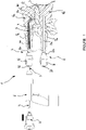
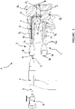
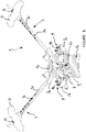
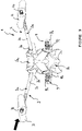
- the figures 1 to 4 are profile views illustrating a spinal segment of a vertebral column in which an intersomatic space is created by means of a transpedicular fusion device according to the present invention.
- the figure 5 is a view from below in the coronal plane of the intervertebral disc D illustrating the lower plateau of the upper vertebra of the spinal segment nibbled by means of the flexible cannulated drill bit of the transpedicular fusion device according to the present invention.
- the Figure 6 is a view showing the flexible cannulated drill bit of the transpedicular fusion device according to the present invention.
- the Picture 7 is a perspective view representing a rachidian segment of a vertebral column cut along a vertical axis making it possible to show the profile of the intersomatic space produced before the introduction of the autologous or biological graft by means of the transpedicular fusion device according to the present invention .
- the Figure 8 is a perspective view illustrating a rachidian segment of a vertebral column cut along a vertical axis making it possible to show in front view the intersomatic space created before the introduction of the autologous or biological graft by means of the transpedicular fusion device according to the present invention.
- FIGS. 9 to 12 are views representing the various stages of preparation, injection of the autologous or biological graft into the intersomatic space and stabilization of a spinal segment by means of the transpedicular fusion device according to the present invention.
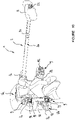
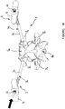
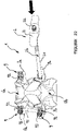
- the figures 13 to 22 are views illustrating variants of the different stages of preparation, injection of the autologous or biological graft into the intersomatic space and stabilization of a spinal segment by means of the transpedicular fusion device according to the present invention
- the figure 23 is a view representing an example of an obturator implanted in the pedicles of the vertebrae of the spinal segment by means of the transpedicular fusion device according to the present invention.
- a fusion device 1 comprising two straight pedicle cannulas 2, 3 per vertebra Va, Vb serving as a safe working channel and as a sighting positioner.
- a right pedicle cannula 2a and 3a will be screwed into each pedicle Pa, while for the vertebra Vb a right pedicle cannula 2b and 3b will be screwed into each pedicle Pb.
- the straight pedicle cannulas 2a, 2b and/or 3a, 3b during transpedicular sighting operations make it possible to guide the various instruments in the direction of the vertebral endplates and at the determined location.
- Each pedicle cannula 2, 3 consists of a tube 20, 30 secured at one of its ends to a gripping head 21, 31.
- the gripping head 21, 31 comprises in its middle a connection means 22, 32 allowing instrument immobilization.
- the fusion device 1 comprises at least one elastically deformable guide pin 4 having, in the deformed position, an end with a pointed curved profile 40 ensuring its implantation in the upper and/or lower plate of the corresponding vertebra Va, Vb. Opposite the end with a curved profile 40, the guide pin 4 cooperates with a gripping system 41 allowing the surgeon to move said pin.
- the fusion device 1 comprises a cannulated drive system 6 on which is mounted a flexible cannulated drill 5 comprising a rigid cannulated rod 50 extending by a flexible longitudinal zone constituted, for example, by a hollow and flexible torsion cable 51 integral at its free end of a cannulated cutter 52 having sharpened profiles ( figure 6 ).
- the cannulated drive system 6 makes it possible to drive said cannulated drill bit 5 back and forth and in rotation so that the cannulated drill bit 52 progressively and in a controlled manner nibbles windows F in said upper and lower plates of each vertebra Va , Vb and shred the nucleic tissue of the intervertebral disc D.
- the fusion device 1 has been shown comprising an injection device 7 which is connected to one of the pedicle cannulas 2a, 2b and 3a, 3b remaining on the operating site for the injection of a graft 8 into the space interbody thus achieved.
- the fusion device 1 comprises obturators 9 which are screwed into the holes left free after removal of the straight pedicle cannulas 2a, 2b and 3a, 3b.
- the obturators 9 consist of pedicle screws 90 connected by connecting rods 91 forming a spinal fixation device known per se.
- the drive system 6 on which the flexible cannulated drill 5 is mounted comprises guide means allowing free passage for the curved guide pin 4.
- the latter prepares the intersomatic operating site by means of the fusion device 1 according to the present invention by carrying out, using various tools and a precise operating mode, windows F in the lower vertebral endplate Pi for the upper Va vertebra and upper Ps for the lower Vb vertebra. These tools also allow shreds of the nucleic tissue of the intervertebral disc D located between the vertebrae above Va and below Vb ( figures 1 to 5 ).
- the straight pedicle cannulas 2a, 2b and 3a, 3b are respectively screwed into the corresponding pedicle Pa, Pb so that the curved pin 4 can reach the lower Pi and upper Ps plates at the location determined by the position of said straight pedicle cannulas 2a , 2b and 3a, 3b and pierce said vertebral endplates Pi and Ps by impaction.
- the flexible cannulated drill bit 5 at its distal end is threaded onto the curved pin 4 which will serve as a guide.
- the flexible cannulated drill 5 is connected to the drive system 6 comprising a motor ensuring the rotational drive of said drill for the production of the windows F.
- the surgeon performs the first drilling or window F of the plates Pi, Ps and of the intervertebral disc D by moving the flexible cannulated drill 5 around the curved guide pin 4.
- the following windows F are produced by progressive nibbling of the plateaus Pi, Ps and of the intervertebral disc D.
- the surgeon moves back the drive system 6 secured to the flexible cannulated drill 5 in order to free the curved part of the guide pin 4.
- the drive system 6 is brought back so that the flexible cannulated drill 5 widens the first hole by nibbling the plates Pi, Ps and the intervertebral disc D in order to create a second window F.
- the surgeon moves the drive system 6 as many times as necessary according to back-and-forth movements around the guide pin 4 so that the flexible cannulated drill 5 produces all of the windows F by nibbling of the vertebral endplates Pi, corresponding Ps ( figures 3 to 5 ).
- the cleaning of the surgical site to be grafted can be carried out by introducing a flexible tube through the cannulas opening into the intranucleic space Es in order to avoid any contact of the physiological liquid with the bone.
- spongy vertebrae Va, Vb ( figure 8 ).
- the introduction of the autologous or biological graft or graft 8 is carried out by means of the injection device 7 which the surgeon connects to one of the straight cannulas 2a, 3a implanted in the upper vertebra Va ( figure 7 and 9 ).
- the autologous graft 8 can be taken from the iliac crest and prepared with specific instruments to obtain a paste whose particle size is compatible with injection through the injection device 7 on the one hand and the cannula on the other. corresponding line 2a, 3a.
- the product is prepared from various components whose particle size matrix is compatible with an injection through on the one hand the injection device 7 and on the other hand the right cannula 2a, 3a corresponding.
- the surgeon performs the injection of the graft 8 through, for example, the straight cannula 3a which is previously connected to the injection device 7, until the flow of the product constituting the graft can be seen. 8 through the other straight cannula 2a in order to check that the intranucleic space Es is perfectly filled.
- a third obturator 9 consisting of a pedicle screw 90 which is screwed into the pedicle of the vertebra Va by means of the right cannula 3a and according to the same procedure as that described previously for the establishment pedicle screws 90 in the lower vertebra Vb ( figure 10 ).
- first connecting rod 91 connecting the pedicle screws 90 located one above the other and integral with the vertebrae Va and Vb.
- the first connecting rod 91 is immobilized in connectors 92 secured to each pedicle screw 90 by means of pressure screws 93. This immobilization is initially limited to guarantee freedom in translation of the connecting rod 91 between the pedicle screws 90 ( figure 10 and 12 ).
- the surgeon continues the injection of the graft 8 via the injection device 7 connected to the remaining straight cannula 2a or 3a with pressurization in order to restore the disc height between the vertebrae Va and Vb of the spinal segment.
- the pressure applied during the injection of the graft 8 between the vertebrae Va and Vb makes it possible to re-tension the annulus.
- This operation is carried out under radiographic control in the operating room and is stopped when the disc height seems satisfactory ( figure 10 and 12 ).
- the surgeon definitively blocks the first connecting rod 91 in the connectors 92 of the pedicle screws 90 by additional tightening of the pressure screws 93.
- the injection device 7 is disconnected from the right cannula 2a and the surgeon places a fourth and final obturator 9 consisting of a pedicle screw 90 which is screwed into the pedicle of the vertebra Va by means of of said straight cannula 2a and according to the same procedure as that described previously for the positioning of the pedicle screws 90 in the lower vertebra Vb.
- the surgeon introduces a second connecting rod 91 connecting the other pedicle screws 90 located one above the other and integral with the vertebrae Va and Vb.
- the second connecting rod 91 is immobilized in connectors 92 secured to each pedicle screw 90 via pressure screws 93 ( figure 11 ).
- the surgeon can adjust the desired lordosis by compression maneuvers using a specific instrument and definitively block the connecting rods 91 in the pedicle screws 90.
- the closure of the four percutaneous incisions is performed in the usual way.
- the compacted graft thanks to its injection under a certain pressure in the space to be grafted acts as an intervertebral prop. Indeed, the graft kept compact in the envelope consisting of the annulus and the vertebral bodies provides effective and dynamic support favorable to fusion.
- the vascularization of the grafted site thanks to the piercing of the vertebral endplates Pi, Ps makes it possible to obtain very favorable conditions (neutral pH and supply of nutrients and bioactive compounds) for rapid and quality fusion.
- the dynamic solicitation and abundant vascularization of the graft significantly reduce the fusion failure rate.
Landscapes
- Health & Medical Sciences (AREA)
- Surgery (AREA)
- Orthopedic Medicine & Surgery (AREA)
- Life Sciences & Earth Sciences (AREA)
- Medical Informatics (AREA)
- Molecular Biology (AREA)
- Veterinary Medicine (AREA)
- Engineering & Computer Science (AREA)
- Biomedical Technology (AREA)
- Heart & Thoracic Surgery (AREA)
- Public Health (AREA)
- Nuclear Medicine, Radiotherapy & Molecular Imaging (AREA)
- Animal Behavior & Ethology (AREA)
- General Health & Medical Sciences (AREA)
- Dentistry (AREA)
- Oral & Maxillofacial Surgery (AREA)
- Neurology (AREA)
- Surgical Instruments (AREA)
- Prostheses (AREA)
- Infusion, Injection, And Reservoir Apparatuses (AREA)
Claims (6)
- Vorrichtung, die das Anbringen und das Injizieren eines autologen oder biologischen Transplantats (6) in einem Zwischenwirbelraum Es erlaubt, der zuvor zwischen einem oberen und einem unteren Wirbel Va, Vb eines Wirbelsegments eingerichtet wird, um eine Zwischenwirbelraumfusion durch vollständig perkutanen transpedikulären Zugang herzustellen, der aus mindestens zwei geraden Pedikularkanülen (2a, 3a; 2b, 3b) besteht, die jeweils entweder auf dem oberen Wirbel Va oder auf dem unteren Wirbel Vb oder auf den beiden Wirbeln Va, Vb des Wirbelsegments eingerichtet sind, mindestens einen Führungsstift (4) mit gekrümmtem Profil, der in der Platte Pi, Ps des entsprechenden Wirbel Va, Vb durch die entsprechende Pedikularkanüle eines biegsamen kanülierten Bohrers (5) implantiert ist, dadurch gekennzeichnet, dass der Bohrer um den entsprechenden Führungsstift (4) geführt und in Hin- und Herbewegungen von einem kanülierten Antriebssystem (6) derart angetrieben ist, dass allmählich und auf gesteuerte Weise Fenster 11 in der unteren Platte Pi und der oberen Platte Ps jedes Wirbels Va, Vb geknabbert werden, und die Nukleingewebe einer Zwischenwirbelscheibe D zur Herstellung des Zwischenwirbelraums Es zerrissen werden, einer Injektionsvorrichtung (7), die an eine der geraden Pedikularkanülen (2a, 3a; 2b, 3b) zur Injektion des Transplantats (8) in den Zwischenwirbelraum Es, der derart hergestellt wird, angeschlossen ist, und Verschlüsse (9), die in die Löcher geschraubt werden, die nach dem Herausziehen der geraden Pedikularkanülen freigelassen werden, besteht
- Vorrichtung nach Anspruch 1, dadurch gekennzeichnet, dass der biegsame kanülierte Bohrer (5) einen starren kanülierten Schaft (50) umfasst, der sich in einer biegsamen Längszone verlängert, die aus einem hohlen und biegsamen Torsionskabel (54) besteht, das an seinem freien Ende fest mit einem kanülierten Fräser (52), der geschliffene Profile aufweist, verbunden ist.
- Vorrichtung nach Anspruch 2, dadurch gekennzeichnet, dass dem kanülierten Fräser (52) entgegengesetzt der starre Schaft (50) des kanülierten Bohrers (5) Verbindungsmittel umfasst, die eingerichtet sind, um eine Verbindung mit dem kanülierten Antriebssystem (6) zu bilden, die es erlaubt, den kanülierten Bohrer (5) in Hin- und Her- und Drehbewegungen anzutreiben, damit der kanülierte Fräser (52) allmählich und auf gesteuerte Weise Fenster F in die untere Platte Pi und die obere Platte Ps jedes Wirbels Va, Vb knabbert, und das Nukleingewebe zerreißt.
- Vorrichtung nach Anspruch 1, dadurch gekennzeichnet, dass der gekrümmte Führungsstift (4) Verbindungsmittel umfasst, die sein Halten, die Steuerung seiner Positionierung und das Ausüben auf dieser Letzteren der Hin- und Herbewegungen erlauben.
- Vorrichtung nach Anspruch 1, dadurch gekennzeichnet, dass die Verschlüsse (9) Pedikelschrauben (90) einer Wirbelbefestigungsvorrichtung sind, die das Anbringen und das Befestigen der Verbindungsschäfte (91) erlaubt.
- Vorrichtung nach Anspruch 5, dadurch gekennzeichnet, dass jede Pedikelschraube (90) einen Verbindungsstecker umfasst, der mit einer Druckschraube (92) zum Stillstellen in Verschiebung und in Drehung eines Verbindungsschafts (91) zusammenwirkt.
Applications Claiming Priority (2)
| Application Number | Priority Date | Filing Date | Title |
|---|---|---|---|
| FR1553398A FR3034977B1 (fr) | 2015-04-16 | 2015-04-16 | Dispositif de fusion transpediculaire percutanee |
| PCT/FR2016/050833 WO2016207501A1 (fr) | 2015-04-16 | 2016-04-11 | Dispositif de fusion transpédiculaire percutanée |
Publications (2)
| Publication Number | Publication Date |
|---|---|
| EP3282958A1 EP3282958A1 (de) | 2018-02-21 |
| EP3282958B1 true EP3282958B1 (de) | 2022-07-20 |
Family
ID=54199756
Family Applications (1)
| Application Number | Title | Priority Date | Filing Date |
|---|---|---|---|
| EP16727744.1A Active EP3282958B1 (de) | 2015-04-16 | 2016-04-11 | Vorrichtung zur perkutanen transpedikulären fusion |
Country Status (6)
| Country | Link |
|---|---|
| EP (1) | EP3282958B1 (de) |
| JP (1) | JP2018511442A (de) |
| CN (1) | CN107530095A (de) |
| FR (1) | FR3034977B1 (de) |
| IL (1) | IL254918A0 (de) |
| WO (1) | WO2016207501A1 (de) |
Families Citing this family (1)
| Publication number | Priority date | Publication date | Assignee | Title |
|---|---|---|---|---|
| CN114305608B (zh) * | 2021-12-24 | 2023-08-15 | 宁波华科润生物科技有限公司 | 一种成角穿刺器及其经皮经单侧椎弓根的椎体融合系统 |
Family Cites Families (10)
| Publication number | Priority date | Publication date | Assignee | Title |
|---|---|---|---|---|
| US6558386B1 (en) * | 2000-02-16 | 2003-05-06 | Trans1 Inc. | Axial spinal implant and method and apparatus for implanting an axial spinal implant within the vertebrae of the spine |
| CN1700889A (zh) * | 2002-08-21 | 2005-11-23 | 小弗兰克·H·伯姆 | 皮下安置腰椎椎弓根螺钉和连接杆的装置和方法 |
| US7828804B2 (en) * | 2002-11-08 | 2010-11-09 | Warsaw Orthopedic, Inc. | Transpedicular intervertebral disk access methods and devices |
| US20060058826A1 (en) * | 2004-08-25 | 2006-03-16 | Evans Avery J | Tissue cavitation device |
| US9381024B2 (en) * | 2005-07-31 | 2016-07-05 | DePuy Synthes Products, Inc. | Marked tools |
| WO2008008522A2 (en) * | 2006-07-13 | 2008-01-17 | Highgate Orthopedics, Inc. | Devices and methods for stabilizing a spinal region |
| US20080255555A1 (en) * | 2007-04-11 | 2008-10-16 | Justis Jeff R | Temporary anchorable tether systems and methods |
| US8974505B2 (en) * | 2008-06-16 | 2015-03-10 | Anna G. U. Sawa | Venting/pressure adjustment to aid in delivery of material into an anatomic region via a cannula |
| CA2790388A1 (en) * | 2010-01-20 | 2011-07-28 | Gamal Baroud | Orthopedic device and method |
| FR2970636B1 (fr) * | 2011-01-24 | 2013-02-15 | Clariance | Dispositif de forage pour la realisation d'un canal osseux a profil courbe a l'interieur du corps d'une vertebre |
-
2015
- 2015-04-16 FR FR1553398A patent/FR3034977B1/fr not_active Expired - Fee Related
-
2016
- 2016-04-11 CN CN201680025401.XA patent/CN107530095A/zh active Pending
- 2016-04-11 JP JP2017554386A patent/JP2018511442A/ja active Pending
- 2016-04-11 WO PCT/FR2016/050833 patent/WO2016207501A1/fr not_active Ceased
- 2016-04-11 EP EP16727744.1A patent/EP3282958B1/de active Active
-
2017
- 2017-10-08 IL IL254918A patent/IL254918A0/en unknown
Also Published As
| Publication number | Publication date |
|---|---|
| JP2018511442A (ja) | 2018-04-26 |
| EP3282958A1 (de) | 2018-02-21 |
| IL254918A0 (en) | 2017-12-31 |
| CN107530095A (zh) | 2018-01-02 |
| FR3034977A1 (fr) | 2016-10-21 |
| FR3034977B1 (fr) | 2017-04-21 |
| WO2016207501A1 (fr) | 2016-12-29 |
Similar Documents
| Publication | Publication Date | Title |
|---|---|---|
| US11147684B2 (en) | Harvesting bone graft material for use in spinal and other bone fusion surgeries | |
| US10751193B2 (en) | Device for percutaneous transpedicular fusion | |
| US10022172B2 (en) | Minimally invasive posterolateral fusion | |
| JP4758912B2 (ja) | 椎間グラフト及び装置を挿入するための方法及び器具 | |
| EP1578315B1 (de) | Vorrichtung für wirbelsäulendistraktion und -fusion | |
| US6921403B2 (en) | Method and apparatus for spinal distraction and fusion | |
| EP2564793B1 (de) | System zur transkorporalen Wirbelsäulendekompression und -reparatur | |
| US7727263B2 (en) | Articulating spinal implant | |
| US6371968B1 (en) | Cavity retaining tool for bone surgery, a cavity retaining tool for general surgery, an endoscopic surgery system involving the use of a cavity retaining tool, and a procedure for surgery | |
| JP4703084B2 (ja) | 脊椎治療用装置 | |
| AU2005234799B2 (en) | Device for treatment or evacuation of intervertebral disc | |
| EP1265541B1 (de) | Axiales wirbelimplantat | |
| US20100145391A1 (en) | Apparatus and method of spinal implant and fusion | |
| US20140303730A1 (en) | Systems and methods for endoscopic vertebral fusion | |
| CA2520472A1 (en) | Apparatus and method for harvesting bone marrow | |
| JP2007526001A (ja) | 経椎弓根的椎間板切除術の方法と装置 | |
| EP2498699A2 (de) | Systeme für transkorporale wirbelsäulendekompression und -reparatur sowie entsprechende verfahren | |
| KR19980702563A (ko) | 사람의 흉추 및 요추 질병을 척추 외측부로부터 수술 교정하기 위한 방법 및 기구 | |
| WO2013009516A2 (en) | Systems and methods for treating a spine through a single vertebral body insertion point | |
| US20110166603A1 (en) | Method and device for placing materials in the spine | |
| WO2016207501A1 (fr) | Dispositif de fusion transpédiculaire percutanée | |
| US8257311B2 (en) | Method and device for treatment of the spine | |
| Lara-Reyna et al. | Initial experience with a full endoscopic facet fusion in combination with endoscopic interbody fusion | |
| US20100106203A1 (en) | Methods and apparatuses for facilitating percutaneous fusion | |
| JP2008517675A (ja) | 脊椎インプラントの同時軸方向送達 |
Legal Events
| Date | Code | Title | Description |
|---|---|---|---|
| STAA | Information on the status of an ep patent application or granted ep patent |
Free format text: STATUS: THE INTERNATIONAL PUBLICATION HAS BEEN MADE |
|
| PUAI | Public reference made under article 153(3) epc to a published international application that has entered the european phase |
Free format text: ORIGINAL CODE: 0009012 |
|
| STAA | Information on the status of an ep patent application or granted ep patent |
Free format text: STATUS: REQUEST FOR EXAMINATION WAS MADE |
|
| 17P | Request for examination filed |
Effective date: 20171103 |
|
| AK | Designated contracting states |
Kind code of ref document: A1 Designated state(s): AL AT BE BG CH CY CZ DE DK EE ES FI FR GB GR HR HU IE IS IT LI LT LU LV MC MK MT NL NO PL PT RO RS SE SI SK SM TR |
|
| AX | Request for extension of the european patent |
Extension state: BA ME |
|
| RIN1 | Information on inventor provided before grant (corrected) |
Inventor name: VIART, GUY Inventor name: GANGI, AFSHIN Inventor name: MAZEL, CHRISTIAN Inventor name: BILLON, ADRIEN Inventor name: SCHULLER, SEBASTIEN Inventor name: LEROY, JEAN YVES Inventor name: STEIB, JEAN PAUL Inventor name: VIRGAUX, NICOLAS |
|
| DAV | Request for validation of the european patent (deleted) | ||
| DAX | Request for extension of the european patent (deleted) | ||
| GRAP | Despatch of communication of intention to grant a patent |
Free format text: ORIGINAL CODE: EPIDOSNIGR1 |
|
| STAA | Information on the status of an ep patent application or granted ep patent |
Free format text: STATUS: GRANT OF PATENT IS INTENDED |
|
| INTG | Intention to grant announced |
Effective date: 20211217 |
|
| GRAJ | Information related to disapproval of communication of intention to grant by the applicant or resumption of examination proceedings by the epo deleted |
Free format text: ORIGINAL CODE: EPIDOSDIGR1 |
|
| GRAP | Despatch of communication of intention to grant a patent |
Free format text: ORIGINAL CODE: EPIDOSNIGR1 |
|
| INTG | Intention to grant announced |
Effective date: 20220218 |
|
| GRAS | Grant fee paid |
Free format text: ORIGINAL CODE: EPIDOSNIGR3 |
|
| GRAA | (expected) grant |
Free format text: ORIGINAL CODE: 0009210 |
|
| STAA | Information on the status of an ep patent application or granted ep patent |
Free format text: STATUS: THE PATENT HAS BEEN GRANTED |
|
| AK | Designated contracting states |
Kind code of ref document: B1 Designated state(s): AL AT BE BG CH CY CZ DE DK EE ES FI FR GB GR HR HU IE IS IT LI LT LU LV MC MK MT NL NO PL PT RO RS SE SI SK SM TR |
|
| REG | Reference to a national code |
Ref country code: CH Ref legal event code: EP |
|
| REG | Reference to a national code |
Ref country code: DE Ref legal event code: R096 Ref document number: 602016073622 Country of ref document: DE |
|
| REG | Reference to a national code |
Ref country code: AT Ref legal event code: REF Ref document number: 1505045 Country of ref document: AT Kind code of ref document: T Effective date: 20220815 |
|
| REG | Reference to a national code |
Ref country code: IE Ref legal event code: FG4D Free format text: LANGUAGE OF EP DOCUMENT: FRENCH |
|
| REG | Reference to a national code |
Ref country code: LT Ref legal event code: MG9D |
|
| REG | Reference to a national code |
Ref country code: NL Ref legal event code: MP Effective date: 20220720 |
|
| PG25 | Lapsed in a contracting state [announced via postgrant information from national office to epo] |
Ref country code: SE Free format text: LAPSE BECAUSE OF FAILURE TO SUBMIT A TRANSLATION OF THE DESCRIPTION OR TO PAY THE FEE WITHIN THE PRESCRIBED TIME-LIMIT Effective date: 20220720 Ref country code: RS Free format text: LAPSE BECAUSE OF FAILURE TO SUBMIT A TRANSLATION OF THE DESCRIPTION OR TO PAY THE FEE WITHIN THE PRESCRIBED TIME-LIMIT Effective date: 20220720 Ref country code: PT Free format text: LAPSE BECAUSE OF FAILURE TO SUBMIT A TRANSLATION OF THE DESCRIPTION OR TO PAY THE FEE WITHIN THE PRESCRIBED TIME-LIMIT Effective date: 20221121 Ref country code: NO Free format text: LAPSE BECAUSE OF FAILURE TO SUBMIT A TRANSLATION OF THE DESCRIPTION OR TO PAY THE FEE WITHIN THE PRESCRIBED TIME-LIMIT Effective date: 20221020 Ref country code: NL Free format text: LAPSE BECAUSE OF FAILURE TO SUBMIT A TRANSLATION OF THE DESCRIPTION OR TO PAY THE FEE WITHIN THE PRESCRIBED TIME-LIMIT Effective date: 20220720 Ref country code: LV Free format text: LAPSE BECAUSE OF FAILURE TO SUBMIT A TRANSLATION OF THE DESCRIPTION OR TO PAY THE FEE WITHIN THE PRESCRIBED TIME-LIMIT Effective date: 20220720 Ref country code: LT Free format text: LAPSE BECAUSE OF FAILURE TO SUBMIT A TRANSLATION OF THE DESCRIPTION OR TO PAY THE FEE WITHIN THE PRESCRIBED TIME-LIMIT Effective date: 20220720 Ref country code: FI Free format text: LAPSE BECAUSE OF FAILURE TO SUBMIT A TRANSLATION OF THE DESCRIPTION OR TO PAY THE FEE WITHIN THE PRESCRIBED TIME-LIMIT Effective date: 20220720 Ref country code: ES Free format text: LAPSE BECAUSE OF FAILURE TO SUBMIT A TRANSLATION OF THE DESCRIPTION OR TO PAY THE FEE WITHIN THE PRESCRIBED TIME-LIMIT Effective date: 20220720 |
|
| REG | Reference to a national code |
Ref country code: AT Ref legal event code: MK05 Ref document number: 1505045 Country of ref document: AT Kind code of ref document: T Effective date: 20220720 |
|
| PG25 | Lapsed in a contracting state [announced via postgrant information from national office to epo] |
Ref country code: PL Free format text: LAPSE BECAUSE OF FAILURE TO SUBMIT A TRANSLATION OF THE DESCRIPTION OR TO PAY THE FEE WITHIN THE PRESCRIBED TIME-LIMIT Effective date: 20220720 Ref country code: IS Free format text: LAPSE BECAUSE OF FAILURE TO SUBMIT A TRANSLATION OF THE DESCRIPTION OR TO PAY THE FEE WITHIN THE PRESCRIBED TIME-LIMIT Effective date: 20221120 Ref country code: HR Free format text: LAPSE BECAUSE OF FAILURE TO SUBMIT A TRANSLATION OF THE DESCRIPTION OR TO PAY THE FEE WITHIN THE PRESCRIBED TIME-LIMIT Effective date: 20220720 Ref country code: GR Free format text: LAPSE BECAUSE OF FAILURE TO SUBMIT A TRANSLATION OF THE DESCRIPTION OR TO PAY THE FEE WITHIN THE PRESCRIBED TIME-LIMIT Effective date: 20221021 |
|
| REG | Reference to a national code |
Ref country code: DE Ref legal event code: R097 Ref document number: 602016073622 Country of ref document: DE |
|
| PG25 | Lapsed in a contracting state [announced via postgrant information from national office to epo] |
Ref country code: SM Free format text: LAPSE BECAUSE OF FAILURE TO SUBMIT A TRANSLATION OF THE DESCRIPTION OR TO PAY THE FEE WITHIN THE PRESCRIBED TIME-LIMIT Effective date: 20220720 Ref country code: RO Free format text: LAPSE BECAUSE OF FAILURE TO SUBMIT A TRANSLATION OF THE DESCRIPTION OR TO PAY THE FEE WITHIN THE PRESCRIBED TIME-LIMIT Effective date: 20220720 Ref country code: DK Free format text: LAPSE BECAUSE OF FAILURE TO SUBMIT A TRANSLATION OF THE DESCRIPTION OR TO PAY THE FEE WITHIN THE PRESCRIBED TIME-LIMIT Effective date: 20220720 Ref country code: CZ Free format text: LAPSE BECAUSE OF FAILURE TO SUBMIT A TRANSLATION OF THE DESCRIPTION OR TO PAY THE FEE WITHIN THE PRESCRIBED TIME-LIMIT Effective date: 20220720 Ref country code: AT Free format text: LAPSE BECAUSE OF FAILURE TO SUBMIT A TRANSLATION OF THE DESCRIPTION OR TO PAY THE FEE WITHIN THE PRESCRIBED TIME-LIMIT Effective date: 20220720 |
|
| PLBE | No opposition filed within time limit |
Free format text: ORIGINAL CODE: 0009261 |
|
| STAA | Information on the status of an ep patent application or granted ep patent |
Free format text: STATUS: NO OPPOSITION FILED WITHIN TIME LIMIT |
|
| PG25 | Lapsed in a contracting state [announced via postgrant information from national office to epo] |
Ref country code: SK Free format text: LAPSE BECAUSE OF FAILURE TO SUBMIT A TRANSLATION OF THE DESCRIPTION OR TO PAY THE FEE WITHIN THE PRESCRIBED TIME-LIMIT Effective date: 20220720 Ref country code: EE Free format text: LAPSE BECAUSE OF FAILURE TO SUBMIT A TRANSLATION OF THE DESCRIPTION OR TO PAY THE FEE WITHIN THE PRESCRIBED TIME-LIMIT Effective date: 20220720 |
|
| 26N | No opposition filed |
Effective date: 20230421 |
|
| PG25 | Lapsed in a contracting state [announced via postgrant information from national office to epo] |
Ref country code: AL Free format text: LAPSE BECAUSE OF FAILURE TO SUBMIT A TRANSLATION OF THE DESCRIPTION OR TO PAY THE FEE WITHIN THE PRESCRIBED TIME-LIMIT Effective date: 20220720 |
|
| PG25 | Lapsed in a contracting state [announced via postgrant information from national office to epo] |
Ref country code: SI Free format text: LAPSE BECAUSE OF FAILURE TO SUBMIT A TRANSLATION OF THE DESCRIPTION OR TO PAY THE FEE WITHIN THE PRESCRIBED TIME-LIMIT Effective date: 20220720 |
|
| REG | Reference to a national code |
Ref country code: DE Ref legal event code: R119 Ref document number: 602016073622 Country of ref document: DE |
|
| REG | Reference to a national code |
Ref country code: CH Ref legal event code: PL |
|
| GBPC | Gb: european patent ceased through non-payment of renewal fee |
Effective date: 20230411 |
|
| PG25 | Lapsed in a contracting state [announced via postgrant information from national office to epo] |
Ref country code: LU Free format text: LAPSE BECAUSE OF NON-PAYMENT OF DUE FEES Effective date: 20230411 |
|
| REG | Reference to a national code |
Ref country code: BE Ref legal event code: MM Effective date: 20230430 |
|
| PG25 | Lapsed in a contracting state [announced via postgrant information from national office to epo] |
Ref country code: MC Free format text: LAPSE BECAUSE OF FAILURE TO SUBMIT A TRANSLATION OF THE DESCRIPTION OR TO PAY THE FEE WITHIN THE PRESCRIBED TIME-LIMIT Effective date: 20220720 |
|
| PG25 | Lapsed in a contracting state [announced via postgrant information from national office to epo] |
Ref country code: GB Free format text: LAPSE BECAUSE OF NON-PAYMENT OF DUE FEES Effective date: 20230411 |
|
| PG25 | Lapsed in a contracting state [announced via postgrant information from national office to epo] |
Ref country code: MC Free format text: LAPSE BECAUSE OF FAILURE TO SUBMIT A TRANSLATION OF THE DESCRIPTION OR TO PAY THE FEE WITHIN THE PRESCRIBED TIME-LIMIT Effective date: 20220720 Ref country code: LI Free format text: LAPSE BECAUSE OF NON-PAYMENT OF DUE FEES Effective date: 20230430 Ref country code: GB Free format text: LAPSE BECAUSE OF NON-PAYMENT OF DUE FEES Effective date: 20230411 Ref country code: DE Free format text: LAPSE BECAUSE OF NON-PAYMENT OF DUE FEES Effective date: 20231103 Ref country code: CH Free format text: LAPSE BECAUSE OF NON-PAYMENT OF DUE FEES Effective date: 20230430 |
|
| REG | Reference to a national code |
Ref country code: IE Ref legal event code: MM4A |
|
| PG25 | Lapsed in a contracting state [announced via postgrant information from national office to epo] |
Ref country code: BE Free format text: LAPSE BECAUSE OF NON-PAYMENT OF DUE FEES Effective date: 20230430 |
|
| PG25 | Lapsed in a contracting state [announced via postgrant information from national office to epo] |
Ref country code: IE Free format text: LAPSE BECAUSE OF NON-PAYMENT OF DUE FEES Effective date: 20230411 |
|
| PG25 | Lapsed in a contracting state [announced via postgrant information from national office to epo] |
Ref country code: IE Free format text: LAPSE BECAUSE OF NON-PAYMENT OF DUE FEES Effective date: 20230411 |
|
| PG25 | Lapsed in a contracting state [announced via postgrant information from national office to epo] |
Ref country code: IT Free format text: LAPSE BECAUSE OF FAILURE TO SUBMIT A TRANSLATION OF THE DESCRIPTION OR TO PAY THE FEE WITHIN THE PRESCRIBED TIME-LIMIT Effective date: 20220720 |
|
| PG25 | Lapsed in a contracting state [announced via postgrant information from national office to epo] |
Ref country code: BG Free format text: LAPSE BECAUSE OF FAILURE TO SUBMIT A TRANSLATION OF THE DESCRIPTION OR TO PAY THE FEE WITHIN THE PRESCRIBED TIME-LIMIT Effective date: 20220720 |
|
| PG25 | Lapsed in a contracting state [announced via postgrant information from national office to epo] |
Ref country code: BG Free format text: LAPSE BECAUSE OF FAILURE TO SUBMIT A TRANSLATION OF THE DESCRIPTION OR TO PAY THE FEE WITHIN THE PRESCRIBED TIME-LIMIT Effective date: 20220720 |
|
| PGFP | Annual fee paid to national office [announced via postgrant information from national office to epo] |
Ref country code: FR Payment date: 20250428 Year of fee payment: 10 |
|
| PG25 | Lapsed in a contracting state [announced via postgrant information from national office to epo] |
Ref country code: CY Free format text: LAPSE BECAUSE OF FAILURE TO SUBMIT A TRANSLATION OF THE DESCRIPTION OR TO PAY THE FEE WITHIN THE PRESCRIBED TIME-LIMIT; INVALID AB INITIO Effective date: 20160411 |
|
| PG25 | Lapsed in a contracting state [announced via postgrant information from national office to epo] |
Ref country code: HU Free format text: LAPSE BECAUSE OF FAILURE TO SUBMIT A TRANSLATION OF THE DESCRIPTION OR TO PAY THE FEE WITHIN THE PRESCRIBED TIME-LIMIT; INVALID AB INITIO Effective date: 20160411 |
|
| PG25 | Lapsed in a contracting state [announced via postgrant information from national office to epo] |
Ref country code: TR Free format text: LAPSE BECAUSE OF FAILURE TO SUBMIT A TRANSLATION OF THE DESCRIPTION OR TO PAY THE FEE WITHIN THE PRESCRIBED TIME-LIMIT Effective date: 20220720 |