EP3282053B1 - Rail mounting system, rail and method for fixing a railway track - Google Patents
Rail mounting system, rail and method for fixing a railway track Download PDFInfo
- Publication number
- EP3282053B1 EP3282053B1 EP17182911.2A EP17182911A EP3282053B1 EP 3282053 B1 EP3282053 B1 EP 3282053B1 EP 17182911 A EP17182911 A EP 17182911A EP 3282053 B1 EP3282053 B1 EP 3282053B1
- Authority
- EP
- European Patent Office
- Prior art keywords
- rail
- clamping
- screw
- tie
- ribbed plate
- Prior art date
- Legal status (The legal status is an assumption and is not a legal conclusion. Google has not performed a legal analysis and makes no representation as to the accuracy of the status listed.)
- Active
Links
- 238000000034 method Methods 0.000 title claims description 9
- 239000004033 plastic Substances 0.000 claims description 24
- 229920003023 plastic Polymers 0.000 claims description 24
- 239000000463 material Substances 0.000 claims description 12
- 239000004696 Poly ether ether ketone Substances 0.000 claims description 6
- 229920002530 polyetherether ketone Polymers 0.000 claims description 6
- 239000002184 metal Substances 0.000 claims description 5
- 239000002131 composite material Substances 0.000 claims description 3
- 241001669679 Eleotris Species 0.000 description 21
- 238000005260 corrosion Methods 0.000 description 5
- 230000007797 corrosion Effects 0.000 description 5
- 230000000694 effects Effects 0.000 description 3
- 238000005553 drilling Methods 0.000 description 2
- 239000011248 coating agent Substances 0.000 description 1
- 238000000576 coating method Methods 0.000 description 1
- 238000010292 electrical insulation Methods 0.000 description 1
- 239000011152 fibreglass Substances 0.000 description 1
- 230000001404 mediated effect Effects 0.000 description 1
- 238000005065 mining Methods 0.000 description 1
- 239000006223 plastic coating Substances 0.000 description 1
Images


Classifications
-
- E—FIXED CONSTRUCTIONS
- E01—CONSTRUCTION OF ROADS, RAILWAYS, OR BRIDGES
- E01B—PERMANENT WAY; PERMANENT-WAY TOOLS; MACHINES FOR MAKING RAILWAYS OF ALL KINDS
- E01B9/00—Fastening rails on sleepers, or the like
- E01B9/02—Fastening rails, tie-plates, or chairs directly on sleepers or foundations; Means therefor
- E01B9/04—Fastening on wooden or concrete sleepers or on masonry without clamp members
- E01B9/10—Screws or bolts for sleepers
Definitions
- the invention relates to a rail fastening system for fastening a railway track to a sill, a track and a method for attaching a railway track to a sill.
- Rail fastening systems and methods of securing a rail track to a threshold are already known.
- a disadvantage of known systems is that they are not desirably corrosion-resistant, in particular when used in a particularly corrosion-prone environment.
- the AT 272 393 B shows an electrical insulation of a rail track relative to the thresholds.
- On the rail foot facing surfaces of the ribbed plate may be provided an electrically insulating self-curing plastic layer.
- the DE 20 2015 005149 U1 discloses a clamp comprising glass fiber reinforced plastic for resiliently securing a track rail.
- the invention has for its object to provide a rail fastening system and a method for fixing a railway track, which are improved in terms of this disadvantage.
- the rail fastening system according to the invention for fastening a rail track to a threshold comprises a sleeper screw and a rail clamping element.
- the sleeper screw is intended for screwing into a threshold.
- the sleeper screw is made entirely of plastic. In this way, the corrosion resistance of the system can be increased.
- exactly four sleeper screws are provided per attachment of the track rail at the sill.
- exactly two sleeper screws are provided per attachment.
- the sleeper screw may have a round thread. In one embodiment, it has no round thread.
- the sleeper screw may have a core diameter that is between 10 mm and 30 mm and may be about 20 mm.
- the thread pitch can be between 10 mm and 15 mm and about 12 mm.
- the thread depth can be between 2 mm and 6 mm and about 4 mm.
- the thread height (preferably the length of the threaded portion) can be between 100 mm and 150 mm and about 125 mm.
- the flank angle of the thread of the sleeper screw is advantageously 43 ° to 22 °.
- the sleeper screw may have a rectangular head as a drive.
- the rail clamping element is also referred to as a clamping element in the context of this document.
- the clamping element cooperates advantageously with the track rail.
- the railway track is also referred to as a rail in the context of this document.
- the clamping element is preferably in direct contact with the rail.
- the clamping element is formed entirely of plastic.
- the clamping element advantageously comprises a clamping plate.
- the clamping plate advantageously has the shape of a cross-sectionally "U" -shaped bent sheet metal part with two legs of different length.
- the clamping plate in this embodiment may have a shape as it is known per se from the so-called superstructure K.
- the thickness of the clamping plate can be between 10 mm and 15 mm and about 12 mm.
- the two legs and the region of the clamping plate connecting the legs have a different thickness.
- the thickness of the longer leg is advantageously greater than the thickness of the connecting region and the thickness of the shorter leg.
- the thickness of the longer leg may be between 10 mm and 20 mm and about 14 mm.
- the thickness of the connecting region may be between 8 mm and 18 mm and about 12 mm.
- the thickness of the shorter leg may be thinner by 1 mm to 5 mm than the thickness of the thicker leg. In this way, an optimal spring action of the clamping plate can be achieved.
- the length of the longer leg can be between 40 mm and 50 mm and about 45 mm.
- the length of the shorter leg can be between 25 mm and 35 mm and about 30 mm.
- the length of the connecting area, so the clear width between the legs can be between 25 mm and 35 mm and about 30 mm.
- the clamping element preferably has a bore, which is preferably penetrated by a clamping screw in the assembled state.
- the clamping element has the shape of a bent wire.
- the clamping element may also be referred to as a tensioning clamp be and, for example, have the form of a so-called Epsilon tension clamp.
- the clamping element may in this embodiment have a shape as it is taken from the so-called superstructure W or superstructure KS known.
- the system includes a ribbed plate.
- the ribbed plate is arranged in the assembled state between rail and threshold, with advantage under the rail.
- the ribbed plate is screwed in the assembled state by means of the sleeper screws with the threshold.
- the ribbed plate is made entirely of plastic.
- the ribbed plate may be formed as it is known from the so-called superstructure K taken alone.
- exactly one ribbed plate per attachment is provided.
- the ribbed plate preferably has guide elements for guiding the foot of the track rail, which may also be referred to as ribs.
- the thickness of the ribbed plate between the ribs may be on average between 10 mm and 20 mm and about 15 mm.
- the surface between the ribs is made oblique, to effect the required rail inclination.
- the thickness of the ribbed plate can be between 30 mm and 50 mm and about 41 mm on the thicker side of the ribbed plate and about 37 mm on the thinner side.
- the thickness of the ribbed plate in the two edge regions, ie outside the ribs, may differ. It can be on the thicker side between 10 mm and 20 mm and about 15 mm and lie on the thinner side between 8 mm and 18 mm and about 13 mm.
- the system comprises a clamping screw by means of which the rail clamping element is arranged on the ribbed plate.
- the clamping screw is completely made of plastic.
- exactly two clamping screws per attachment are provided. In the assembled state, the clamping screw advantageously clamps the clamping element against the rail.
- the ribbed plate has a threaded bore into which the clamping screw is screwed in the mounted state.
- each ribbed plate has exactly Two threaded holes, in each of which exactly one clamping screw is screwed.
- the clamping screw advantageously comprises a threaded rod, so preferably has no head.
- the threaded rod is screwed into the threaded hole of the clamping plate with advantage.
- the clamping screw comprises in the embodiment in which it has a threaded rod, with advantage a clamping nut, which cooperates with the threaded rod.
- the clamping nut and / or the threaded rod can be made entirely of plastic.
- the clamping nut is bolted with advantage to the threaded rod.
- the clamping nut preferably acts on the clamping element.
- the threaded rod is screwed at one end to the ribbed plate and at the other end of the threaded rod is advantageously arranged the clamping nut and further preferably cooperates with the clamping element.
- the clamping nut advantageously biases the clamping element against the rail.
- the clamping screw is formed as a conventional screw head.
- the length of the threaded rod can be between 60 mm and 100 mm and about 80 mm.
- the outer diameter of the threaded rod can be between 20 mm and 30 mm and about 22 mm, it can be an M22 threaded rod.
- the pitch of the thread of the threaded rod can be between 0.5 and 3.0 and is preferably 2.5.
- the inner diameter of the clamping nut can be between 20 mm and 30 mm and about 22 mm.
- the clamping nut may be an M22 nut, which may be a hexagon nut.
- the pitch of the thread of the clamping nut can be between 0.5 and 3.0 and is preferably 2.5.
- the clamping nut can have a spanner width of 36 mm. In axial direction, it may have a height which is between 10 mm and 30 mm and may be 22 mm.
- the threads of the clamping nut and threaded rod can be an ISO metric thread.
- the system comprises spring elements, which are preferably arranged between clamping screw and clamping element and more preferably comprise plastic.
- the spring elements may be designed as washers.
- the spring elements may be formed entirely of plastic.
- the washers can not be made entirely flush to effect or enhance the spring characteristic.
- the washers can also be designed plan.
- the system may include washers of different materials. It can be sandwiched two harder washers combined with a softer washer.
- the thickness of the washers may be between 2.5 mm and 7.5 mm and about 5 mm.
- the outer diameter of the washers may be between 40 mm and 50 mm and about 45 mm.
- the system also includes spring elements which are arranged in the assembled state between the sleeper screw and ribbed plate. These can be designed as the spring elements, which are preferably arranged between the clamping screw and the clamping element.
- the rail fastening system includes the sill, clamp, ribbed plate, clamping screw, and spring element elements. In one embodiment, the rail fastening system is composed solely of these elements.
- the system has no metal surfaces. As a result, a large corrosion resistance is given.
- the plastic of all or individual elements of the rail fastening system may be or include polyetheretherketone (PEEK).
- PEEK polyetheretherketone
- the density of the plastic of all or individual elements of the rail fastening system is advantageously 1.30 ⁇ 0.02 g / cm 3 .
- the tensile strength of the plastic is advantageously greater than or equal to 100 N / mm 2 .
- the elongation at break of the plastic is advantageously greater than or equal to 12%.
- the system is made entirely of plastic All materials used constitute a composite and have the same material properties.
- the invention also relates to a track with sleepers and with track rails, which are fastened by means of a rail fastening system, in particular a rail fastening system according to one of claims 1 to 6, to the sleepers.
- the railway tracks are plastic coated. The coating can completely envelop the rail body or leave areas, in particular the running surface of the rail, free.
- the object is achieved by a method for fastening a rail track on a threshold, in which the rail is fastened on a slow-moving route and / or in a particularly corrosion-prone environment with a system according to one of claims 1 to 6 at a threshold.
- the slow-travel route may be, for example, a factory site.
- the slow driving distance may be a distance where the speed is limited to 80, 70, 60, 50, 40, 30, 20 or 10 km / h.
- the environment particularly prone to corrosion is advantageously an environment with corrosive conditions.
- the most vulnerable environment may be a factory site, such as mining industrial tracks, especially for bottling plants.
- the threaded rod is screwed, preferably in the ribbed plate and before or after the rail on the ribbed plate, directly or mediated by an intermediate layer, placed.
- the clamping element is preferably mounted, which advantageously has a bore or recess which can be pushed onto the threaded rod and therefore a guidance of the clamping element is effected during assembly by the threaded rod.
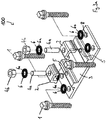
- the as a whole with 100 designated, in the Figures 1 to 3a shown rail fastening system for fastening a rail track at a threshold has four sleeper screws 1, on each of which a spring element 6 is arranged.
- the sleeper screws 1 engage in the threshold (not shown in the figures).
- the system comprises a ribbed plate 3, which rests in the assembled state above directly or indirectly on the threshold.
- the ribbed plate 3 comprises two guide elements 7, which in the assembled state the foot the rail between them.
- the guide elements can also be referred to as ribs (see, for example Fig. 6 ).
- the system comprises two clamping screws 4, by means of which the two rail clamping elements 2 are arranged on the ribbed plate 3.
- each clamping element 2 has a bore 2b (see, for example FIGS. 10 and 12 ), which is penetrated by the clamping screw 4 in the assembled state.
- the clamping screw 4 engages in threaded holes 5 of the ribbed plate 3, more precisely, the ribs 7.
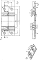
- Die FIGS. 3a . 4 and 5 show that the ribbed plate has holes 8, and each hole 8 is penetrated in the mounted state of a sleeper screw 1.
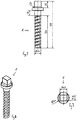
- the clamping screw 4 in the illustrated embodiment is not a screw having a head, but comprises a threaded rod 4a and a clamping nut 4b.
- a spring element 6 is arranged between the clamping screw 4, more precisely the clamping nut 4b, and the rail clamping element 2, a spring element 6 is arranged.
- this spring element 6 is formed as a washer 6a. It is conceivable that this spring element 6 in each case comprises two outer washers and an intermediate disc (not shown in the figures). The washer may then be made of a softer plastic than the outer washers.
- a spring element 6 is arranged in each case (see Fig. 3a ). This is formed by a washer 6a and is executed in the illustrated embodiment as the spring element 6 shown between clamping nut 4b and clamping element 2. Also, this spring element 6 may in principle each comprise two outer washers and an intermediate disc (not shown in the figures) and the intermediate disc may then be made of a softer plastic than the outer washers.
- Fig. 5 results in the thickness of the ribbed plate in the embodiment shown between the ribs on average about 15 mm and the surface between the ribs 7 is made oblique, to effect the required rail inclination.
- Fig. 5 also shows that the thickness of the ribbed plate in the region of the ribs on the thicker side of the ribbed plate is about 41 mm and on the thinner side about 37 mm. It can also be seen that the thickness of the ribbed plate in the two edge regions is different and on the thicker side about 15 mm is on the thinner side about 13 mm.
- the sleeper screw has a rectangular drive head measuring 26.6 mm by 19.8 mm ( 8 and 9 ).
- the clamping element 2 has in the illustrated embodiment, the shape of a cross-sectionally "U" -shaped sheet metal part with two different lengths of legs. It can also be referred to as a clamping plate.
- a different thickness and the thickness of the longer leg is about 14 mm.
- the thickness of the connecting area is about 12 mm.
- the thickness of the shorter leg is less than the thickness of the thicker leg.
- the length of the longer leg is about 45 mm.
- the length of the shorter leg is about 30 mm.
- the length of the connecting area, so the clear width between the legs is about 30 mm.
- Fig. 13 shows that the outer diameter of the washers 6a in the illustrated embodiment is about 45 mm.
- the thickness of the washers 6a in the illustrated embodiment is about 5 mm.
- Fig. 15 shows that the length of the threaded rod 4a in the illustrated embodiment is about 80 mm and it is an M22 threaded rod and the slope is 2.5.
- the clamping nut 4b is an M22 nut fitting to the threaded rod 4a. It is designed as a hexagon nut with a wrench size of 36 mm and has a height of 22 mm.
- the system 100 has no metal surfaces. All elements of the system, ie sleeper screws 1, ribbed plate 3, rail clamping element 2, clamping screw 4 with threaded rod and clamping nut and washers 6a are made of plastic and that of polyetheretherketone (PEEK). The system is highly corrosion resistant in this way.
Landscapes
- Engineering & Computer Science (AREA)
- Mechanical Engineering (AREA)
- Architecture (AREA)
- Civil Engineering (AREA)
- Structural Engineering (AREA)
- Railway Tracks (AREA)
- Connection Of Plates (AREA)
Description
Die Erfindung betrifft ein Schienenbefestigungssystem zur Befestigung einer Bahnschiene an einer Schwelle, ein Gleis und ein Verfahren zur Befestigung einer Bahnschiene an einer Schwelle.The invention relates to a rail fastening system for fastening a railway track to a sill, a track and a method for attaching a railway track to a sill.
Schienenbefestigungssysteme und Verfahren zur Befestigung einer Bahnschiene an einer Schwelle sind bereits bekannt. Nachteilig an bekannten Systemen ist, dass sie nicht in wünschenswerter Weise - insbesondere bei Anwendung in besonders korrosionsgefährdeter Umgebung - korrosionsbeständig sind.Rail fastening systems and methods of securing a rail track to a threshold are already known. A disadvantage of known systems is that they are not desirably corrosion-resistant, in particular when used in a particularly corrosion-prone environment.
Aus der
Die
Aus der
Die
Die Erfindung hat es sich zur Aufgabe gemacht, ein Schienenbefestigungssystem und ein Verfahren zur Befestigung einer Bahnschiene zu schaffen, welche hinsichtlich dieses Nachteils verbessert sind.The invention has for its object to provide a rail fastening system and a method for fixing a railway track, which are improved in terms of this disadvantage.
Diese Aufgabe wird durch das in Anspruch 1 wiedergegebene Schienenbefestigungssystem, das in Anspruch 7 wiedergegebene Gleis und das in Anspruch 8 wiedergegebene Verfahren gelöst.This object is achieved by the rail fastening system recited in
Das erfindungsgemäße Schienenbefestigungssystem zur Befestigung einer Bahnschiene an einer Schwelle umfasst eine Schwellenschraube und ein Schienenklemmelement. Die Schwellenschraube ist zum Einschrauben in eine Schwelle vorgesehen. Die Schwellenschraube ist vollständig aus Kunststoff gefertigt. Auf diese Weise kann die Korrosionsbeständigkeit des Systems gesteigert werden. In einer Ausführungsform sind genau vier Schwellenschrauben pro Befestigung der Bahnschiene an der Schwelle vorgesehen. In einer anderen Ausführungsform sind genau zwei Schwellenschrauben pro Befestigung vorgesehen. Die Schwellenschraube kann ein Rundgewinde aufweisen. In einer Ausführungsform weist sie kein Rundgewinde auf.The rail fastening system according to the invention for fastening a rail track to a threshold comprises a sleeper screw and a rail clamping element. The sleeper screw is intended for screwing into a threshold. The sleeper screw is made entirely of plastic. In this way, the corrosion resistance of the system can be increased. In one embodiment, exactly four sleeper screws are provided per attachment of the track rail at the sill. In another embodiment, exactly two sleeper screws are provided per attachment. The sleeper screw may have a round thread. In one embodiment, it has no round thread.
Die Schwellenschraube kann einen Kerndurchmesser aufweisen, der zwischen 10 mm und 30 mm liegt und etwa 20 mm betragen kann. Die Gewindesteigung kann zwischen 10 mm und 15 mm liegen und etwa 12 mm betragen. Die Gewindetiefe kann zwischen 2 mm und 6 mm liegen und etwa 4 mm betragen. Die Gewindehöhe (bevorzugt also die Länge des Gewindebereichs) kann zwischen 100 mm und 150 mm liegen und etwa 125 mm betragen. Der Flankenwinkel des Gewindes der Schwellenschraube beläuft sich mit Vorteil auf 43° zu 22°. Die Schwellenschraube kann einen Rechteckkopf als Antrieb aufweisen.The sleeper screw may have a core diameter that is between 10 mm and 30 mm and may be about 20 mm. The thread pitch can be between 10 mm and 15 mm and about 12 mm. The thread depth can be between 2 mm and 6 mm and about 4 mm. The thread height (preferably the length of the threaded portion) can be between 100 mm and 150 mm and about 125 mm. The flank angle of the thread of the sleeper screw is advantageously 43 ° to 22 °. The sleeper screw may have a rectangular head as a drive.
Das Schienenklemmelement wird im Rahmen dieser Druckschrift auch kurz als Klemmelement bezeichnet. Das Klemmelement wirkt mit Vorteil mit der Bahnschiene zusammen. Die Bahnschiene wird im Rahmen dieser Druckschrift auch kurz als Schiene bezeichnet. Das Klemmelement steht bei ordnungsgemäßer Anwendung bevorzugt in unmittelbarem Kontakt mit der Schiene. Vorzugsweise sind pro Befestigung genau zwei Klemmelemente vorgesehen. Das Klemmelement ist vollständig aus Kunststoff gebildet.The rail clamping element is also referred to as a clamping element in the context of this document. The clamping element cooperates advantageously with the track rail. The railway track is also referred to as a rail in the context of this document. When properly used, the clamping element is preferably in direct contact with the rail. Preferably, exactly two clamping elements are provided per attachment. The clamping element is formed entirely of plastic.
Das Klemmelement umfasst mit Vorteil eine Klemmplatte. Die Klemmplatte hat mit Vorteil die Form eines im Querschnitt "U"-förmigen Blechbiegeteils mit zwei unterschiedlich langen Schenkeln. Die Klemmplatte kann in dieser Ausführungsform eine Form aufweisen, wie sie für sich genommen aus dem sogenannten Oberbau K bekannt ist. Die Dicke der Klemmplatte kann zwischen 10 mm und 15 mm liegen und etwa 12 mm betragen. In einer Ausführungsform weisen die beiden Schenkel und der die Schenkel verbindende Bereich der Klemmplatte eine unterschiedliche Dicke auf. Die Dicke des längeren Schenkels ist mit Vorteil größer, als die Dicke des verbindenden Bereichs und die Dicke des kürzeren Schenkels. Die Dicke des längeren Schenkels kann zwischen 10 mm und 20 mm liegen und etwa 14 mm betragen. Die Dicke des verbindenden Bereichs kann zwischen 8 mm und 18 mm liegen und etwa 12 mm betragen. Die Dicke des kürzeren Schenkels kann um 1 mm bis 5 mm dünner sein, als die Dicke des dickeren Schenkels. Auf diese Weise kann eine optimale Federwirkung der Klemmplatte erzielt werden. Die Länge des längeren Schenkels kann zwischen 40 mm und 50 mm liegen und etwa 45 mm betragen. Die Länge des kürzeren Schenkels kann zwischen 25 mm und 35 mm liegen und etwa 30 mm betragen. Die Länge des verbindenden Bereichs, also die lichte Weite zwischen den Schenkeln kann zwischen 25 mm und 35 mm liegen und etwa 30 mm betragen. Das Klemmelement weist bevorzugt eine Bohrung auf, die im montierten Zustand bevorzugt von einer Klemmschraube durchgriffen ist.The clamping element advantageously comprises a clamping plate. The clamping plate advantageously has the shape of a cross-sectionally "U" -shaped bent sheet metal part with two legs of different length. The clamping plate in this embodiment may have a shape as it is known per se from the so-called superstructure K. The thickness of the clamping plate can be between 10 mm and 15 mm and about 12 mm. In one embodiment, the two legs and the region of the clamping plate connecting the legs have a different thickness. The thickness of the longer leg is advantageously greater than the thickness of the connecting region and the thickness of the shorter leg. The thickness of the longer leg may be between 10 mm and 20 mm and about 14 mm. The thickness of the connecting region may be between 8 mm and 18 mm and about 12 mm. The thickness of the shorter leg may be thinner by 1 mm to 5 mm than the thickness of the thicker leg. In this way, an optimal spring action of the clamping plate can be achieved. The length of the longer leg can be between 40 mm and 50 mm and about 45 mm. The length of the shorter leg can be between 25 mm and 35 mm and about 30 mm. The length of the connecting area, so the clear width between the legs can be between 25 mm and 35 mm and about 30 mm. The clamping element preferably has a bore, which is preferably penetrated by a clamping screw in the assembled state.
Grundsätzlich ist denkbar, dass das Klemmelement die Form eines gebogenen Drahtes hat. In der Ausführungsform, in der das Klemmelement die Form eines gebogenen Drahtes hat, kann das Klemmelement auch als Spannklemme bezeichnet werden und beispielsweise die Form einer sogenannten Epsilon-Spannklemme aufweisen. Das Klemmelement kann in dieser Ausführungsform eine Form aufweisen, wie sie für sich genommen aus dem sogenannten Oberbau W oder Oberbau KS bekannt ist.In principle, it is conceivable that the clamping element has the shape of a bent wire. In the embodiment in which the clamping element has the shape of a bent wire, the clamping element may also be referred to as a tensioning clamp be and, for example, have the form of a so-called Epsilon tension clamp. The clamping element may in this embodiment have a shape as it is taken from the so-called superstructure W or superstructure KS known.
Das System umfasst eine Rippenplatte. Die Rippenplatte ist im montierten Zustand zwischen Schiene und Schwelle angeordnet, mit Vorteil unter der Schiene. Die Rippenplatte ist im montierten Zustand mittels der Schwellenschrauben mit der Schwelle verschraubt. Die Rippenplatte ist vollständig aus Kunststoff gefertigt. Die Rippenplatte kann so ausgeformt sein, wie es aus dem sogenannten Oberbau K für sich genommen bekannt ist. Mit Vorteil ist genau eine Rippenplatte pro Befestigung vorgesehen. Die Rippenplatte weist bevorzugt Führungselemente auf, zur Führung des Fußes der Bahnschiene, die auch als Rippen bezeichnet werden können. Die Dicke der Rippenplatte zwischen den Rippen kann im Mittel zwischen 10 mm und 20 mm liegen und etwa 15 mm betragen. Mit Vorteil ist die Oberfläche zwischen den Rippen schräg ausgeführt, zur Bewirkung der erforderlichen Schienenneigung. Im Bereich der Rippen kann die Dicke der Rippenplatte zwischen 30 mm und 50 mm liegen und an der dickeren Seite der Rippenplatte etwa 41 mm betragen und an der dünneren Seite etwa 37 mm. Die Dicke der Rippenplatte in den beiden Randbereichen, also außerhalb der Rippen, kann sich unterscheiden. Sie kann auf der dickeren Seite zwischen 10 mm und 20 mm liegen und etwa 15 mm betragen und auf der dünneren Seite zwischen 8 mm und 18 mm liegen und etwa 13 mm betragen.The system includes a ribbed plate. The ribbed plate is arranged in the assembled state between rail and threshold, with advantage under the rail. The ribbed plate is screwed in the assembled state by means of the sleeper screws with the threshold. The ribbed plate is made entirely of plastic. The ribbed plate may be formed as it is known from the so-called superstructure K taken alone. Advantageously, exactly one ribbed plate per attachment is provided. The ribbed plate preferably has guide elements for guiding the foot of the track rail, which may also be referred to as ribs. The thickness of the ribbed plate between the ribs may be on average between 10 mm and 20 mm and about 15 mm. Advantageously, the surface between the ribs is made oblique, to effect the required rail inclination. In the area of the ribs, the thickness of the ribbed plate can be between 30 mm and 50 mm and about 41 mm on the thicker side of the ribbed plate and about 37 mm on the thinner side. The thickness of the ribbed plate in the two edge regions, ie outside the ribs, may differ. It can be on the thicker side between 10 mm and 20 mm and about 15 mm and lie on the thinner side between 8 mm and 18 mm and about 13 mm.
Das System umfasst eine Klemmschraube, mittels derer das Schienenklemmelement an der Rippenplatte angeordnet ist. Die Klemmschraube ist vollständig aus Kunststoff gebildet. Mit Vorteil sind genau zwei Klemmschrauben pro Befestigung vorgesehen. Im montierten Zustand spannt die Klemmschraube mit Vorteil das Klemmelement gegen die Schiene.The system comprises a clamping screw by means of which the rail clamping element is arranged on the ribbed plate. The clamping screw is completely made of plastic. Advantageously, exactly two clamping screws per attachment are provided. In the assembled state, the clamping screw advantageously clamps the clamping element against the rail.
Die Rippenplatte weist eine Gewindebohrung auf, in welche die Klemmschraube im montierten Zustand eingeschraubt ist. Mit Vorteil weist jede Rippenplatte genau zwei Gewindebohrungen auf, in die jeweils genau eine Klemmschraube eingeschraubt ist.The ribbed plate has a threaded bore into which the clamping screw is screwed in the mounted state. Advantageously, each ribbed plate has exactly Two threaded holes, in each of which exactly one clamping screw is screwed.
Die Klemmschraube umfasst mit Vorteil eine Gewindestange, weist bevorzugt also keinen Kopf auf. Die Gewindestange ist mit Vorteil in die Gewindebohrung der Klemmplatte eingeschraubt. Die Klemmschraube umfasst in der Ausführungsform, in der sie eine Gewindestange aufweist, mit Vorteil eine Klemm-Mutter, die mit der Gewindestange zusammenwirkt. Die Klemm-Mutter und/oder die Gewindestange können vollständig aus Kunststoff gefertigt sein. Die Klemm-Mutter ist mit Vorteil mit der Gewindestange verschraubt. Die Klemm-Mutter wirkt bevorzugt auf das Klemmelement. Bevorzugt ist im montierten Zustand die Gewindestange einenends mit der Rippenplatte verschraubt und an dem anderen Ende der Gewindestange ist mit Vorteil die Klemm-Mutter angeordnet und wirkt weiter bevorzugt mit dem Klemmelement zusammen. Im montierten Zustand spannt die Klemm-Mutter mit Vorteil das Klemmelement gegen die Schiene. Grundsätzlich ist denkbar, dass die Klemmschraube als gewöhnliche Schraube mit Kopf ausgeformt ist. Durch die bevorzugte Ausgestaltung als Gewindestange mit Klemm-Mutter kann jedoch eine vereinfachte Montage der Bahnschiene an der Schwelle erreicht werden, da die Gewindestange in die Klemmplatte eingeschraubt werden kann, daraufhin die Schiene auf die Rippenplatte aufgelegt werden kann, daraufhin das Klemmelement angeordnet werden kann, wobei die Gewindestange als Führung wirkt und schließlich die Klemm-Mutter montiert werden kann. Die Länge der Gewindestange kann zwischen 60 mm und 100 mm liegen und etwa 80 mm betragen. Der Außendurchmesser der Gewindestange kann zwischen 20 mm und 30 mm liegen und etwa 22 mm betragen, es kann sich um eine M22 Gewindestange handeln. Die Steigung des Gewindes der Gewindestange kann zwischen 0,5 und 3,0 liegen und beträgt bevorzugt 2,5.The clamping screw advantageously comprises a threaded rod, so preferably has no head. The threaded rod is screwed into the threaded hole of the clamping plate with advantage. The clamping screw comprises in the embodiment in which it has a threaded rod, with advantage a clamping nut, which cooperates with the threaded rod. The clamping nut and / or the threaded rod can be made entirely of plastic. The clamping nut is bolted with advantage to the threaded rod. The clamping nut preferably acts on the clamping element. Preferably, in the mounted state, the threaded rod is screwed at one end to the ribbed plate and at the other end of the threaded rod is advantageously arranged the clamping nut and further preferably cooperates with the clamping element. When assembled, the clamping nut advantageously biases the clamping element against the rail. In principle, it is conceivable that the clamping screw is formed as a conventional screw head. Due to the preferred embodiment as a threaded rod with clamping nut, however, a simplified mounting of the track rail can be achieved at the threshold, since the threaded rod can be screwed into the clamping plate, then the rail can be placed on the ribbed plate, then the clamping element can be arranged wherein the threaded rod acts as a guide and finally the clamping nut can be mounted. The length of the threaded rod can be between 60 mm and 100 mm and about 80 mm. The outer diameter of the threaded rod can be between 20 mm and 30 mm and about 22 mm, it can be an M22 threaded rod. The pitch of the thread of the threaded rod can be between 0.5 and 3.0 and is preferably 2.5.
Der Innendurchmesser der Klemm-Mutter kann zwischen 20 mm und 30 mm liegen und etwa 22 mm betragen. Bei der Klemm-Mutter kann es sich um einen M22 Mutter handeln, die als Sechskant-Mutter ausgeführt sein kann. Die Steigung des Gewindes der Klemm-Mutter kann zwischen 0,5 und 3,0 liegen und beträgt bevorzugt 2,5. Die Klemm-Mutter kann eine Schlüsselweite von 36 mm aufweisen. In axialer Richtung kann sie eine Höhe aufweisen, die zwischen 10 mm und 30 mm liegt und 22 mm betragen kann.The inner diameter of the clamping nut can be between 20 mm and 30 mm and about 22 mm. The clamping nut may be an M22 nut, which may be a hexagon nut. The pitch of the thread of the clamping nut can be between 0.5 and 3.0 and is preferably 2.5. The clamping nut can have a spanner width of 36 mm. In axial direction, it may have a height which is between 10 mm and 30 mm and may be 22 mm.
Bei den Gewinden von Klemm-Mutter und Gewindestange kann es sich um ein metrisches ISO-Gewinde handeln.The threads of the clamping nut and threaded rod can be an ISO metric thread.
Mit Vorteil umfasst das System Federelemente, die bevorzugt zwischen Klemmschraube und Klemmelement angeordnet sind und weiter bevorzugt Kunststoff umfassen. Die Federelemente können als Unterlegscheiben ausgeführt sein. Die Federelemente können vollständig aus Kunststoff gebildet sein. Die Unterlegscheiben können nicht ganz plan ausgeführt sein, um die Federeigenschaft zu bewirken oder zu steigern. Die Unterlegscheiben können jedoch auch plan ausgeführt sein. Das System kann Unterlegscheiben aus verschiedenen Materialien umfassen. Es können sandwichartig zwei härtere Unterlegscheiben mit einer weicheren Zwischenscheibe kombiniert sein. Die Dicke der Unterlegscheiben kann zwischen 2,5 mm und 7,5 mm liegen und etwa 5 mm betragen. Der Außendurchmesser der Unterlegscheiben kann zwischen 40 mm und 50 mm liegen und etwa 45 mm betragen.Advantageously, the system comprises spring elements, which are preferably arranged between clamping screw and clamping element and more preferably comprise plastic. The spring elements may be designed as washers. The spring elements may be formed entirely of plastic. The washers can not be made entirely flush to effect or enhance the spring characteristic. However, the washers can also be designed plan. The system may include washers of different materials. It can be sandwiched two harder washers combined with a softer washer. The thickness of the washers may be between 2.5 mm and 7.5 mm and about 5 mm. The outer diameter of the washers may be between 40 mm and 50 mm and about 45 mm.
In einer Ausführungsform umfasst das System auch Federelemente, die im montierten Zustand zwischen Schwellenschraube und Rippenplatte angeordnet sind. Diese können wie die Federelemente, die bevorzugt zwischen Klemmschraube und Klemmelement angeordnet sind, ausgeführt sein.In one embodiment, the system also includes spring elements which are arranged in the assembled state between the sleeper screw and ribbed plate. These can be designed as the spring elements, which are preferably arranged between the clamping screw and the clamping element.
In einer Ausführungsform umfasst das Schienenbefestigungssystem die Elemente Schwelleschraube, Klemmelement, Rippenplatte, Klemmschraube und Federelement. In einer Ausführungsform ist das Schienenbefestigungssystem ausschließlich aus diesen Elementen zusammengesetzt.In one embodiment, the rail fastening system includes the sill, clamp, ribbed plate, clamping screw, and spring element elements. In one embodiment, the rail fastening system is composed solely of these elements.
Das System weist keine Metalloberflächen auf. Hierdurch ist eine große Korrosionsbeständigkeit gegeben.The system has no metal surfaces. As a result, a large corrosion resistance is given.
Der Kunststoff aller oder einzelner Elemente des Schienenbefestigungssystems kann Polyetheretherketon (PEEK) sein oder umfassen. Die Dichte des Kunststoffs aller oder einzelner Elemente des Schienenbefestigungssystems beträgt mit Vorteil 1,30 +/- 0,02 g/cm3. Die Zugfestigkeit des Kunststoffs ist mit Vorteil größer gleich 100 N/mm2. Die Reißdehnung des Kunststoffs ist mit Vorteil größer oder gleich 12 %. Das System ist vollständig aus Kunststoff gefertigt
Alle verwendeten Materialien stellen einen Verbund dar und weisen die gleichen Materialeigenschaften auf.The plastic of all or individual elements of the rail fastening system may be or include polyetheretherketone (PEEK). The density of the plastic of all or individual elements of the rail fastening system is advantageously 1.30 ± 0.02 g / cm 3 . The tensile strength of the plastic is advantageously greater than or equal to 100 N / mm 2 . The elongation at break of the plastic is advantageously greater than or equal to 12%. The system is made entirely of plastic
All materials used constitute a composite and have the same material properties.
Die Erfindung betrifft auch ein Gleis mit Schwellen und mit Bahnschienen, die mittels eines Schienenbefestigungssystems, insbesondere eines Schienenbefestigungssystems nach einem der Ansprüche 1 bis 6, an den Schwellen befestigt sind. Die Bahnschienen sind kunststoffbeschichtet. Die Beschichtung kann den Schienenkörper vollständig umhüllen oder Bereiche, insbesondere die Lauffläche der Schiene, freilassen.The invention also relates to a track with sleepers and with track rails, which are fastened by means of a rail fastening system, in particular a rail fastening system according to one of
In dem Verfahrensaspekt wird die Aufgabe gelöst durch ein Verfahren zur Befestigung einer Bahnschiene auf einer Schwelle, bei dem die Schiene auf einer Langsamfahrstrecke und/oder in einer besonders korrosionsgefährdeten Umgebung mit einem System nach einem der Ansprüche 1 bis 6 an einer Schwelle befestigt wird. Bei der Langsamfahrstrecke kann es sich beispielsweise um ein Fabrikgelände handeln. Die Langsamfahrstrecke kann eine Strecke sein, auf der die Geschwindigkeit auf 80, 70, 60, 50, 40, 30, 20 oder 10 km/h beschränkt ist.In the method aspect, the object is achieved by a method for fastening a rail track on a threshold, in which the rail is fastened on a slow-moving route and / or in a particularly corrosion-prone environment with a system according to one of
Die besonders korrosionsgefährdete Umgebung ist mit Vorteil eine Umgebung mit korrosionsfördernden Verhältnissen. Bei der besonders korrosionsgefährdeten Umgebung kann es sich um ein Fabrikgelände handeln, etwa Bergbau- Industriegleise, insbesondere für Abfüllanlagen.The environment particularly prone to corrosion is advantageously an environment with corrosive conditions. The most vulnerable environment may be a factory site, such as mining industrial tracks, especially for bottling plants.
Bei einem bevorzugten Verfahren zur Befestigung der Bahnschiene auf der Schwelle wird die Gewindestange eingeschraubt, bevorzugt in die Rippenplatte und davor oder anschließend die Schiene auf die Rippenplatte, unmittelbar oder vermittelt durch eine Zwischenschicht, aufgelegt.In a preferred method for fastening the track rail on the threshold, the threaded rod is screwed, preferably in the ribbed plate and before or after the rail on the ribbed plate, directly or mediated by an intermediate layer, placed.
Daraufhin wird bevorzugt das Klemmelement montiert, wobei dieses mit Vorteil eine Bohrung oder Ausnehmung aufweist, die auf die Gewindestange aufschiebbar ist und daher eine Führung des Klemmelements bei der Montage durch die Gewindestange bewirkt wird.Then, the clamping element is preferably mounted, which advantageously has a bore or recess which can be pushed onto the threaded rod and therefore a guidance of the clamping element is effected during assembly by the threaded rod.
Anschließend folgt mit Vorteil die Montage der Klemm-Mutter auf der Gewindestange.Then follows with advantage the assembly of the clamping nut on the threaded rod.
Die Erfindung soll nun anhand eines in den Zeichnungen gezeigten Ausführungsbeispiels näher erläutert werden. Es zeigen:
- Fig. 1
- eine perspektivische Darstellung eines Ausführungsbeispiels eines erfindungsgemäßen Schienenbefestigungssystems;
- Fig. 2
- eine Seitenansicht des Schienenbefestigungssystems nach
Fig. 1 ; - Fig. 3
- eine Frontalansicht des in
Fig. 1 gezeigten Schienenbefestigungssystems; - Fig. 3a
- eine Explosionsdarstellung des in
Fig. 1 gezeigten Schienenbefestigungssystems; - Fig. 4
- eine Ansicht von oben auf die Rippenplatte,
- Fig. 5
- eine Frontalansicht der Rippenplatte von
Fig. 4 ; - Fig. 6
- eine perspektivische Darstellung der in
Fig. 4 gezeigten Rippenplatte in kleinerem Maßstab; - Fig. 7
- eine Seitenansicht einer Schwellenschraube;
- Fig. 8
- eine perspektivische Darstellung der in
Fig. 7 gezeigten Schwellenschraube; - Fig. 9
- eine Ansicht von oben auf die in
Fig. 7 gezeigte Schwellenschraube; - Fig. 10
- eine Ansicht von oben auf eine Klemmplatte;
- Fig. 11
- eine Seitendarstellung der in
Fig. 10 gezeigten Klemmplatte; - Fig. 12
- eine perspektivische Darstellung der in
Fig. 10 gezeigten Klemmplatte; - Fig. 13
- eine Ansicht von oben auf ein Federelement;
- Fig. 14
- eine Seitenansicht des in
Fig. 13 gezeigten Federelements; - Fig. 15
- eine Seitendarstellung einer Gewindestange;
- Fig. 16
- eine Ansicht von oben auf eine Klemm-Mutter;
- Fig. 17
- eine Seitenansicht der in
Fig. 16 gezeigten Klemm-Mutter.
- Fig. 1
- a perspective view of an embodiment of a rail fastening system according to the invention;
- Fig. 2
- a side view of the rail fastening system according to
Fig. 1 ; - Fig. 3
- a frontal view of the in
Fig. 1 shown rail fastening system; - Fig. 3a
- an exploded view of the in
Fig. 1 shown rail fastening system; - Fig. 4
- a view from above of the ribbed plate,
- Fig. 5
- a frontal view of the ribbed plate of
Fig. 4 ; - Fig. 6
- a perspective view of in
Fig. 4 shown ribbed plate on a smaller scale; - Fig. 7
- a side view of a sleeper screw;
- Fig. 8
- a perspective view of in
Fig. 7 shown threshold screw; - Fig. 9
- a view from the top of the in
Fig. 7 sleeper screw shown; - Fig. 10
- a view from above of a clamping plate;
- Fig. 11
- a page representation of in
Fig. 10 shown clamping plate; - Fig. 12
- a perspective view of in
Fig. 10 shown clamping plate; - Fig. 13
- a view from above of a spring element;
- Fig. 14
- a side view of the in
Fig. 13 shown spring element; - Fig. 15
- a page illustration of a threaded rod;
- Fig. 16
- a view from above of a clamping nut;
- Fig. 17
- a side view of in
Fig. 16 shown clamping nut.
Das als Ganzes mit 100 bezeichnete, in den
Etwa
Auch zwischen der Schwellenschraube 1 und der Rippenplatte 3 ist jeweils ein Federelement 6 angeordnet (siehe etwa
Wie sich aus
Wie
Das Klemmelement 2 hat im gezeigten Ausführungsbeispiel die Form eines im Querschnitt "U"-förmigen Blechbiegeteils mit zwei unterschiedlich langen Schenkeln. Es kann auch als Klemmplatte bezeichnet werden.The clamping
Wie
Wie
Wie aus den
Das System 100 weist keine Metalloberflächen auf. Alle Elemente des Systems, also Schwellenschrauben 1, Rippenplatte 3, Schienenklemmelement 2, Klemmschraube 4 mit Gewindestange und Klemm-Mutter sowie Unterlegscheiben 6a sind aus Kunststoff gefertigt und zwar aus Polyetheretherketon (PEEK). Das System ist auf diese Weise höchst korrosionsbeständig.The
- 100100
- SchienenbefestigungssystemRail fastening system
- 11
- Schwellenschraubesleeper screw
- 22
- SchienenklemmelementRail clamping element
- 2a2a
- Klemmplatteclamp
- 2b2 B
- Bohrungdrilling
- 33
- Rippenplatterib plate
- 44
- Klemmschraubeclamping screw
- 4a4a
- Gewindestangethreaded rod
- 4b4b
- Klemm-MutterClamping nut
- 55
- Gewindebohrungthreaded hole
- 66
- Federelementespring elements
- 6a6a
- Unterlegscheibewasher
- 77
- Rippenribs
- 88th
- Bohrungendrilling
Claims (8)
- Rail fastening system (100) for fastening a railway rail to a tie, comprising a tie screw (1) for screwing into a tie, and a rail clamping element (2), the system (100) comprising a ribbed plate (3) for being arranged between the railway rail and the tie and for being screwed to the tie by means of the tie screw (1), the system (100) comprising a clamping screw (4), by means of which the rail clamping element (2) is arranged on the ribbed plate (3), the ribbed plate (3) comprising a threaded hole (5), into which the clamping screw (4) is screwed, characterized in that the system (100) is completely made of plastics material and in that all the materials used form a composite and have the same material properties.
- System according to claim 1, characterized in that the rail clamping element (2) comprises plastics material.
- System according to either claim 1 or claim 2, characterized in that the clamping screw (4) comprises a threaded rod (4a).
- System according to claim 3, characterized in that the clamping screw (4) comprises a clamping nut (4b) that interacts with the threaded rod (4a) and the clamping nut (4b) comprises plastics material.
- System according to any of claims 1 to 4, characterized in that the system (100) comprises spring elements (6) that are arranged between the clamping screw (4) and the rail clamping element (2) and comprise plastics material.
- System according to any of claims 1 to 5, characterized in that the system (100) has no metal surfaces and the plastics material comprises polyetheretherketone (PEEK), and all the materials of the system that are used form a composite and have the same material properties.
- Track comprising ties and railway rails that are fastened to the ties by means of a rail fastening system according to any of claims 1 to 6, wherein the railway rails are plastic-coated.
- Method for fastening a railway rail to a tie, wherein, on a low-speed section and in a particularly corrosion-prone environment, the railway rail is fastened to a tie by means of a system according to any of claims 1 to 6.
Priority Applications (1)
| Application Number | Priority Date | Filing Date | Title |
|---|---|---|---|
| PL17182911T PL3282053T3 (en) | 2016-08-11 | 2017-07-25 | Rail mounting system, rail and method for fixing a railway track |
Applications Claiming Priority (1)
| Application Number | Priority Date | Filing Date | Title |
|---|---|---|---|
| DE102016114903.9A DE102016114903A1 (en) | 2016-08-11 | 2016-08-11 | Rail fastening system, track and method for attaching a track rail |
Publications (2)
| Publication Number | Publication Date |
|---|---|
| EP3282053A1 EP3282053A1 (en) | 2018-02-14 |
| EP3282053B1 true EP3282053B1 (en) | 2019-05-29 |
Family
ID=59399299
Family Applications (1)
| Application Number | Title | Priority Date | Filing Date |
|---|---|---|---|
| EP17182911.2A Active EP3282053B1 (en) | 2016-08-11 | 2017-07-25 | Rail mounting system, rail and method for fixing a railway track |
Country Status (4)
| Country | Link |
|---|---|
| EP (1) | EP3282053B1 (en) |
| DE (1) | DE102016114903A1 (en) |
| ES (1) | ES2743375T3 (en) |
| PL (1) | PL3282053T3 (en) |
Family Cites Families (7)
| Publication number | Priority date | Publication date | Assignee | Title |
|---|---|---|---|---|
| DE1761633U (en) * | 1957-10-25 | 1958-02-20 | Schmitthelm Fa Ernst | FEATHER NAIL. |
| DE1097470B (en) * | 1959-04-30 | 1961-01-19 | Duesseldorfer Eisenhuettengese | Sleeper screw |
| AT272393B (en) * | 1968-01-25 | 1969-07-10 | Republik Oesterreich Vertreten | Electrical insulation of a rail line from the sleepers |
| NL1021990C2 (en) * | 2002-11-25 | 2004-05-26 | Edilon Bv | Rail construction with cladding structure. |
| DE102010020801B4 (en) * | 2010-05-18 | 2013-03-14 | Wirthwein Ag | rail fastening |
| AT514682A1 (en) * | 2013-07-25 | 2015-02-15 | Wolfgang Ing Kummer | Railway sleeper and arrangement in the superstructure of a track |
| DE202015005149U1 (en) * | 2015-07-21 | 2015-10-16 | Otto Alte-Teigeler Gmbh | Rail fastening for prestressing a rail for tram / industrial / crane / railway tracks while simultaneously minimizing feedthrough |
-
2016
- 2016-08-11 DE DE102016114903.9A patent/DE102016114903A1/en not_active Ceased
-
2017
- 2017-07-25 ES ES17182911T patent/ES2743375T3/en active Active
- 2017-07-25 PL PL17182911T patent/PL3282053T3/en unknown
- 2017-07-25 EP EP17182911.2A patent/EP3282053B1/en active Active
Non-Patent Citations (1)
| Title |
|---|
| None * |
Also Published As
| Publication number | Publication date |
|---|---|
| EP3282053A1 (en) | 2018-02-14 |
| PL3282053T3 (en) | 2019-11-29 |
| ES2743375T3 (en) | 2020-02-18 |
| DE102016114903A1 (en) | 2018-02-15 |
Similar Documents
| Publication | Publication Date | Title |
|---|---|---|
| EP2888407B1 (en) | Plastic plug for securing a rail | |
| EP2992144B1 (en) | Rail bed | |
| WO2013079210A2 (en) | Fastening device having an anchor and a reinforcement | |
| DE102006024440B4 (en) | Screw | |
| EP3437954B1 (en) | Protection device | |
| DE202013103906U1 (en) | Sleeper screw for fastening a rail and combination of such a sleeper screw and a plastic anchor | |
| EP3282053B1 (en) | Rail mounting system, rail and method for fixing a railway track | |
| DE3827773C2 (en) | Fastening device for rails | |
| DE3737591C2 (en) | Screw-dowel combination | |
| EP2551408B1 (en) | System for fixing a rail to a base | |
| WO2009010038A1 (en) | Concrete sleeper | |
| DE102005024441B4 (en) | Heart block | |
| EP3450629A1 (en) | Vehicle restraint system with concrete screw | |
| DE102017118131A1 (en) | Means and methods for impact welding of rail breaks | |
| DE102013107320A1 (en) | Shim and rail mounting point | |
| DE102013221175B4 (en) | Angle guide plate | |
| DE202011104261U1 (en) | System for securing a rail to a substrate | |
| EP1830002B1 (en) | Track structure adapted for tramways | |
| EP2426257A1 (en) | Expansion insert for rail nail | |
| DE4212786A1 (en) | Rail arrangement for permanent way - has intermediate layer with flexible section between rail foot and ribbed base plate | |
| AT507990B1 (en) | CONNECTING COMPONENT AND CONNECTING ARRANGEMENT FOR THE FLUID CONNECTION OF ADJUSTABLE DOUBLE-STAB, FLAT-STABILIZED OR COMBINED DOUBLE-STABILIZED GRATING MATS AND FENCE THEREFOR | |
| DE202013101664U1 (en) | Dowel for fixing a rail and combination of such a dowel with a reinforcing element and attachment point for a rail | |
| DE9317008U1 (en) | screw | |
| DE102015106924B4 (en) | Arrangement for mounting a rail track and associated rail track | |
| DE102009048949A1 (en) | Concrete sleeper comprises mounting device and through bolt which is plunged in concrete sleeper by through hole having recess with extended diameter at lower side of concrete sleeper |
Legal Events
| Date | Code | Title | Description |
|---|---|---|---|
| PUAI | Public reference made under article 153(3) epc to a published international application that has entered the european phase |
Free format text: ORIGINAL CODE: 0009012 |
|
| STAA | Information on the status of an ep patent application or granted ep patent |
Free format text: STATUS: THE APPLICATION HAS BEEN PUBLISHED |
|
| AK | Designated contracting states |
Kind code of ref document: A1 Designated state(s): AL AT BE BG CH CY CZ DE DK EE ES FI FR GB GR HR HU IE IS IT LI LT LU LV MC MK MT NL NO PL PT RO RS SE SI SK SM TR |
|
| AX | Request for extension of the european patent |
Extension state: BA ME |
|
| STAA | Information on the status of an ep patent application or granted ep patent |
Free format text: STATUS: REQUEST FOR EXAMINATION WAS MADE |
|
| 17P | Request for examination filed |
Effective date: 20180626 |
|
| RBV | Designated contracting states (corrected) |
Designated state(s): AL AT BE BG CH CY CZ DE DK EE ES FI FR GB GR HR HU IE IS IT LI LT LU LV MC MK MT NL NO PL PT RO RS SE SI SK SM TR |
|
| GRAP | Despatch of communication of intention to grant a patent |
Free format text: ORIGINAL CODE: EPIDOSNIGR1 |
|
| STAA | Information on the status of an ep patent application or granted ep patent |
Free format text: STATUS: GRANT OF PATENT IS INTENDED |
|
| INTG | Intention to grant announced |
Effective date: 20190213 |
|
| GRAS | Grant fee paid |
Free format text: ORIGINAL CODE: EPIDOSNIGR3 |
|
| GRAA | (expected) grant |
Free format text: ORIGINAL CODE: 0009210 |
|
| STAA | Information on the status of an ep patent application or granted ep patent |
Free format text: STATUS: THE PATENT HAS BEEN GRANTED |
|
| AK | Designated contracting states |
Kind code of ref document: B1 Designated state(s): AL AT BE BG CH CY CZ DE DK EE ES FI FR GB GR HR HU IE IS IT LI LT LU LV MC MK MT NL NO PL PT RO RS SE SI SK SM TR |
|
| REG | Reference to a national code |
Ref country code: GB Ref legal event code: FG4D Free format text: NOT ENGLISH |
|
| REG | Reference to a national code |
Ref country code: CH Ref legal event code: EP |
|
| REG | Reference to a national code |
Ref country code: DE Ref legal event code: R081 Ref document number: 502017001425 Country of ref document: DE Owner name: YNCORIS GMBH & CO. KG, DE Free format text: FORMER OWNER: INFRASERV GMBH & CO. KNAPSACK KG, 50354 HUERTH, DE |
|
| REG | Reference to a national code |
Ref country code: AT Ref legal event code: REF Ref document number: 1138333 Country of ref document: AT Kind code of ref document: T Effective date: 20190615 |
|
| REG | Reference to a national code |
Ref country code: DE Ref legal event code: R096 Ref document number: 502017001425 Country of ref document: DE |
|
| REG | Reference to a national code |
Ref country code: IE Ref legal event code: FG4D Free format text: LANGUAGE OF EP DOCUMENT: GERMAN |
|
| REG | Reference to a national code |
Ref country code: NL Ref legal event code: HC Owner name: YNCORIS GMBH & CO. KG; DE Free format text: DETAILS ASSIGNMENT: CHANGE OF OWNER(S), CHANGE OF OWNER(S) NAME; FORMER OWNER NAME: INFRASERV GMBH & CO. KNAPSACK KG Effective date: 20190620 |
|
| RAP2 | Party data changed (patent owner data changed or rights of a patent transferred) |
Owner name: YNCORIS GMBH & CO. KG |
|
| REG | Reference to a national code |
Ref country code: NL Ref legal event code: FP |
|
| REG | Reference to a national code |
Ref country code: LT Ref legal event code: MG4D |
|
| PG25 | Lapsed in a contracting state [announced via postgrant information from national office to epo] |
Ref country code: HR Free format text: LAPSE BECAUSE OF FAILURE TO SUBMIT A TRANSLATION OF THE DESCRIPTION OR TO PAY THE FEE WITHIN THE PRESCRIBED TIME-LIMIT Effective date: 20190529 Ref country code: LT Free format text: LAPSE BECAUSE OF FAILURE TO SUBMIT A TRANSLATION OF THE DESCRIPTION OR TO PAY THE FEE WITHIN THE PRESCRIBED TIME-LIMIT Effective date: 20190529 Ref country code: PT Free format text: LAPSE BECAUSE OF FAILURE TO SUBMIT A TRANSLATION OF THE DESCRIPTION OR TO PAY THE FEE WITHIN THE PRESCRIBED TIME-LIMIT Effective date: 20190930 Ref country code: NO Free format text: LAPSE BECAUSE OF FAILURE TO SUBMIT A TRANSLATION OF THE DESCRIPTION OR TO PAY THE FEE WITHIN THE PRESCRIBED TIME-LIMIT Effective date: 20190829 Ref country code: FI Free format text: LAPSE BECAUSE OF FAILURE TO SUBMIT A TRANSLATION OF THE DESCRIPTION OR TO PAY THE FEE WITHIN THE PRESCRIBED TIME-LIMIT Effective date: 20190529 Ref country code: SE Free format text: LAPSE BECAUSE OF FAILURE TO SUBMIT A TRANSLATION OF THE DESCRIPTION OR TO PAY THE FEE WITHIN THE PRESCRIBED TIME-LIMIT Effective date: 20190529 Ref country code: AL Free format text: LAPSE BECAUSE OF FAILURE TO SUBMIT A TRANSLATION OF THE DESCRIPTION OR TO PAY THE FEE WITHIN THE PRESCRIBED TIME-LIMIT Effective date: 20190529 |
|
| PG25 | Lapsed in a contracting state [announced via postgrant information from national office to epo] |
Ref country code: BG Free format text: LAPSE BECAUSE OF FAILURE TO SUBMIT A TRANSLATION OF THE DESCRIPTION OR TO PAY THE FEE WITHIN THE PRESCRIBED TIME-LIMIT Effective date: 20190829 Ref country code: LV Free format text: LAPSE BECAUSE OF FAILURE TO SUBMIT A TRANSLATION OF THE DESCRIPTION OR TO PAY THE FEE WITHIN THE PRESCRIBED TIME-LIMIT Effective date: 20190529 Ref country code: RS Free format text: LAPSE BECAUSE OF FAILURE TO SUBMIT A TRANSLATION OF THE DESCRIPTION OR TO PAY THE FEE WITHIN THE PRESCRIBED TIME-LIMIT Effective date: 20190529 Ref country code: GR Free format text: LAPSE BECAUSE OF FAILURE TO SUBMIT A TRANSLATION OF THE DESCRIPTION OR TO PAY THE FEE WITHIN THE PRESCRIBED TIME-LIMIT Effective date: 20190830 |
|
| PG25 | Lapsed in a contracting state [announced via postgrant information from national office to epo] |
Ref country code: EE Free format text: LAPSE BECAUSE OF FAILURE TO SUBMIT A TRANSLATION OF THE DESCRIPTION OR TO PAY THE FEE WITHIN THE PRESCRIBED TIME-LIMIT Effective date: 20190529 Ref country code: CZ Free format text: LAPSE BECAUSE OF FAILURE TO SUBMIT A TRANSLATION OF THE DESCRIPTION OR TO PAY THE FEE WITHIN THE PRESCRIBED TIME-LIMIT Effective date: 20190529 Ref country code: RO Free format text: LAPSE BECAUSE OF FAILURE TO SUBMIT A TRANSLATION OF THE DESCRIPTION OR TO PAY THE FEE WITHIN THE PRESCRIBED TIME-LIMIT Effective date: 20190529 Ref country code: SK Free format text: LAPSE BECAUSE OF FAILURE TO SUBMIT A TRANSLATION OF THE DESCRIPTION OR TO PAY THE FEE WITHIN THE PRESCRIBED TIME-LIMIT Effective date: 20190529 Ref country code: DK Free format text: LAPSE BECAUSE OF FAILURE TO SUBMIT A TRANSLATION OF THE DESCRIPTION OR TO PAY THE FEE WITHIN THE PRESCRIBED TIME-LIMIT Effective date: 20190529 |
|
| REG | Reference to a national code |
Ref country code: ES Ref legal event code: FG2A Ref document number: 2743375 Country of ref document: ES Kind code of ref document: T3 Effective date: 20200218 |
|
| PG25 | Lapsed in a contracting state [announced via postgrant information from national office to epo] |
Ref country code: SM Free format text: LAPSE BECAUSE OF FAILURE TO SUBMIT A TRANSLATION OF THE DESCRIPTION OR TO PAY THE FEE WITHIN THE PRESCRIBED TIME-LIMIT Effective date: 20190529 Ref country code: MC Free format text: LAPSE BECAUSE OF FAILURE TO SUBMIT A TRANSLATION OF THE DESCRIPTION OR TO PAY THE FEE WITHIN THE PRESCRIBED TIME-LIMIT Effective date: 20190529 |
|
| REG | Reference to a national code |
Ref country code: DE Ref legal event code: R097 Ref document number: 502017001425 Country of ref document: DE |
|
| PG25 | Lapsed in a contracting state [announced via postgrant information from national office to epo] |
Ref country code: TR Free format text: LAPSE BECAUSE OF FAILURE TO SUBMIT A TRANSLATION OF THE DESCRIPTION OR TO PAY THE FEE WITHIN THE PRESCRIBED TIME-LIMIT Effective date: 20190529 |
|
| PLBE | No opposition filed within time limit |
Free format text: ORIGINAL CODE: 0009261 |
|
| STAA | Information on the status of an ep patent application or granted ep patent |
Free format text: STATUS: NO OPPOSITION FILED WITHIN TIME LIMIT |
|
| REG | Reference to a national code |
Ref country code: BE Ref legal event code: MM Effective date: 20190731 |
|
| 26N | No opposition filed |
Effective date: 20200303 |
|
| PG25 | Lapsed in a contracting state [announced via postgrant information from national office to epo] |
Ref country code: BE Free format text: LAPSE BECAUSE OF NON-PAYMENT OF DUE FEES Effective date: 20190731 Ref country code: SI Free format text: LAPSE BECAUSE OF FAILURE TO SUBMIT A TRANSLATION OF THE DESCRIPTION OR TO PAY THE FEE WITHIN THE PRESCRIBED TIME-LIMIT Effective date: 20190529 Ref country code: LU Free format text: LAPSE BECAUSE OF NON-PAYMENT OF DUE FEES Effective date: 20190725 |
|
| PG25 | Lapsed in a contracting state [announced via postgrant information from national office to epo] |
Ref country code: IE Free format text: LAPSE BECAUSE OF NON-PAYMENT OF DUE FEES Effective date: 20190725 |
|
| REG | Reference to a national code |
Ref country code: CH Ref legal event code: PL |
|
| PG25 | Lapsed in a contracting state [announced via postgrant information from national office to epo] |
Ref country code: LI Free format text: LAPSE BECAUSE OF NON-PAYMENT OF DUE FEES Effective date: 20200731 Ref country code: CH Free format text: LAPSE BECAUSE OF NON-PAYMENT OF DUE FEES Effective date: 20200731 |
|
| PG25 | Lapsed in a contracting state [announced via postgrant information from national office to epo] |
Ref country code: CY Free format text: LAPSE BECAUSE OF FAILURE TO SUBMIT A TRANSLATION OF THE DESCRIPTION OR TO PAY THE FEE WITHIN THE PRESCRIBED TIME-LIMIT Effective date: 20190529 |
|
| PG25 | Lapsed in a contracting state [announced via postgrant information from national office to epo] |
Ref country code: IS Free format text: LAPSE BECAUSE OF FAILURE TO SUBMIT A TRANSLATION OF THE DESCRIPTION OR TO PAY THE FEE WITHIN THE PRESCRIBED TIME-LIMIT Effective date: 20190929 |
|
| PG25 | Lapsed in a contracting state [announced via postgrant information from national office to epo] |
Ref country code: HU Free format text: LAPSE BECAUSE OF FAILURE TO SUBMIT A TRANSLATION OF THE DESCRIPTION OR TO PAY THE FEE WITHIN THE PRESCRIBED TIME-LIMIT; INVALID AB INITIO Effective date: 20170725 Ref country code: MT Free format text: LAPSE BECAUSE OF FAILURE TO SUBMIT A TRANSLATION OF THE DESCRIPTION OR TO PAY THE FEE WITHIN THE PRESCRIBED TIME-LIMIT Effective date: 20190529 |
|
| PG25 | Lapsed in a contracting state [announced via postgrant information from national office to epo] |
Ref country code: MK Free format text: LAPSE BECAUSE OF FAILURE TO SUBMIT A TRANSLATION OF THE DESCRIPTION OR TO PAY THE FEE WITHIN THE PRESCRIBED TIME-LIMIT Effective date: 20190529 |
|
| REG | Reference to a national code |
Ref country code: DE Ref legal event code: R082 Ref document number: 502017001425 Country of ref document: DE Representative=s name: PATENTANWAELTE KLUIN DEBELIUS WEBER PARTG MBB, DE |
|
| P01 | Opt-out of the competence of the unified patent court (upc) registered |
Effective date: 20230526 |
|
| PGFP | Annual fee paid to national office [announced via postgrant information from national office to epo] |
Ref country code: IT Payment date: 20230711 Year of fee payment: 7 Ref country code: GB Payment date: 20230713 Year of fee payment: 7 Ref country code: ES Payment date: 20230810 Year of fee payment: 7 Ref country code: AT Payment date: 20230710 Year of fee payment: 7 |
|
| PGFP | Annual fee paid to national office [announced via postgrant information from national office to epo] |
Ref country code: FR Payment date: 20230710 Year of fee payment: 7 Ref country code: DE Payment date: 20230731 Year of fee payment: 7 |
|
| PGFP | Annual fee paid to national office [announced via postgrant information from national office to epo] |
Ref country code: PL Payment date: 20240502 Year of fee payment: 8 |
|
| PGFP | Annual fee paid to national office [announced via postgrant information from national office to epo] |
Ref country code: NL Payment date: 20240722 Year of fee payment: 8 |