EP3281753A1 - Robot - Google Patents
Robot Download PDFInfo
- Publication number
- EP3281753A1 EP3281753A1 EP16306052.8A EP16306052A EP3281753A1 EP 3281753 A1 EP3281753 A1 EP 3281753A1 EP 16306052 A EP16306052 A EP 16306052A EP 3281753 A1 EP3281753 A1 EP 3281753A1
- Authority
- EP
- European Patent Office
- Prior art keywords
- lubricant
- reservoir
- transmission
- manipulator
- protective device
- Prior art date
- Legal status (The legal status is an assumption and is not a legal conclusion. Google has not performed a legal analysis and makes no representation as to the accuracy of the status listed.)
- Granted
Links
- 230000005540 biological transmission Effects 0.000 claims abstract description 114
- 239000000314 lubricant Substances 0.000 claims abstract description 107
- 230000001681 protective effect Effects 0.000 claims abstract description 62
- 230000007246 mechanism Effects 0.000 claims abstract description 16
- 238000010521 absorption reaction Methods 0.000 claims abstract description 5
- 230000008859 change Effects 0.000 claims description 7
- 239000011230 binding agent Substances 0.000 claims description 4
- 235000013305 food Nutrition 0.000 description 12
- 238000004519 manufacturing process Methods 0.000 description 5
- 238000011109 contamination Methods 0.000 description 4
- 210000000245 forearm Anatomy 0.000 description 4
- 238000009434 installation Methods 0.000 description 4
- XLYOFNOQVPJJNP-UHFFFAOYSA-N water Substances O XLYOFNOQVPJJNP-UHFFFAOYSA-N 0.000 description 4
- 238000005299 abrasion Methods 0.000 description 2
- 238000007373 indentation Methods 0.000 description 2
- 239000007788 liquid Substances 0.000 description 2
- 239000010687 lubricating oil Substances 0.000 description 2
- 238000007789 sealing Methods 0.000 description 2
- 239000007787 solid Substances 0.000 description 2
- 230000009471 action Effects 0.000 description 1
- 230000033228 biological regulation Effects 0.000 description 1
- 238000004140 cleaning Methods 0.000 description 1
- 230000007423 decrease Effects 0.000 description 1
- 230000002950 deficient Effects 0.000 description 1
- 230000001419 dependent effect Effects 0.000 description 1
- 238000011161 development Methods 0.000 description 1
- 230000018109 developmental process Effects 0.000 description 1
- 238000011156 evaluation Methods 0.000 description 1
- 239000004519 grease Substances 0.000 description 1
- 238000007689 inspection Methods 0.000 description 1
- 238000005461 lubrication Methods 0.000 description 1
- 238000012423 maintenance Methods 0.000 description 1
- 238000000034 method Methods 0.000 description 1
- 238000003801 milling Methods 0.000 description 1
- 230000003287 optical effect Effects 0.000 description 1
- 238000004806 packaging method and process Methods 0.000 description 1
- 230000008569 process Effects 0.000 description 1
- 238000009420 retrofitting Methods 0.000 description 1
- 238000012549 training Methods 0.000 description 1
Images


Classifications
-
- B—PERFORMING OPERATIONS; TRANSPORTING
- B25—HAND TOOLS; PORTABLE POWER-DRIVEN TOOLS; MANIPULATORS
- B25J—MANIPULATORS; CHAMBERS PROVIDED WITH MANIPULATION DEVICES
- B25J19/00—Accessories fitted to manipulators, e.g. for monitoring, for viewing; Safety devices combined with or specially adapted for use in connection with manipulators
- B25J19/0075—Means for protecting the manipulator from its environment or vice versa
-
- B—PERFORMING OPERATIONS; TRANSPORTING
- B25—HAND TOOLS; PORTABLE POWER-DRIVEN TOOLS; MANIPULATORS
- B25J—MANIPULATORS; CHAMBERS PROVIDED WITH MANIPULATION DEVICES
- B25J19/00—Accessories fitted to manipulators, e.g. for monitoring, for viewing; Safety devices combined with or specially adapted for use in connection with manipulators
- B25J19/0062—Lubrication means
Definitions
- the present invention relates to a manipulator, in particular a robot, preferably a delta robot.
- the manipulator is particularly suitable for hygienic environments and includes a manipulator mechanism, such as a robot arm, a motor and a transmission with a transmission housing.
- a predetermined volume of lubricant is present in the transmission housing and the transmission is operatively connected to the engine.
- the transmission is designed to drive the manipulator mechanism by means of an output.
- Manipulators such as delta robots, are used in many automated fields, including the manufacture and packaging of food products. In the production of food or in other areas requiring special hygiene, it is of particular importance to avoid soiling of the products. In particular, it must be avoided that lubricant from the transmission housing reaches the products or the food.
- a manipulator according to claim 1 and in particular in that on the gear housing, a protective device is mounted, which includes a reservoir, which is designed for permanent absorption of lubricant exiting from the transmission, wherein the reservoir for receiving at least 30th % of the predetermined volume of the lubricant is established.
- the invention is based on the recognition that, for example, a wear-out seal can be dispensed with by the permanent absorption of lubricant exiting from the transmission in the reservoir, and nevertheless permanent protection against escaping lubricant can be provided. According to the invention can thus be dispensed with additional seals that bear against moving parts and thus subject to heavy wear.
- a large proportion (ie at least 30%) of the lubricant of the transmission can be permanently absorbed. In this way it is possible that both smaller and larger Leaks in the transmission housing do not pollute the production of food and the like unnoticed. As a result, it can be avoided that large parts of a production by lubricant become unusable.
- the manipulator according to the invention is therefore not only suitable for hygienic environments but can e.g. can also be used in clean rooms. It is additionally advantageous here that the protective device not only lubricates, but also e.g. Abrasion of the transmission can withhold.
- the volume of the reservoir may also amount to at least 30% of the predetermined volume of the lubricant.
- the manipulator may be, for example, a robot with at least three axes.
- the manipulator is a delta robot with in particular three frame-fixed mounted rotation axes and a work platform, which is spatially parallelogram.
- the delta robot can comprise three motors each with one gearbox and one protective device each.
- the delta robot may further comprise a housing which is fixedly mounted. In the housing, the motors can immovably, ie be arranged immovable.
- the motors can each drive an upper arm by means of a gearbox.
- a parallel plate can be moved, wherein the parallel plate preferably coupled by means of ball joints with three forearms is.
- the forearms can each be coupled via further ball joints with the respective upper arm.
- a gear can be operatively coupled to each motor, with a separate protective device preferably being attached to each gearbox of the gearbox.
- the robot may generally be parallel kinematic.
- the manipulator mechanism may comprise a robot arm and / or a gripper.
- the manipulator may also be a SCARA robot (Selective Compliance Assembly Robot Arm ), ie it may be a horizontal articulated arm robot.
- SCARA robot Selective Compliance Assembly Robot Arm
- the manipulator may also be, for example, a press, a machine tool, a conveyor belt and the like.
- the manipulator mechanism may in particular comprise a pump, a saw, a milling cutter or a roller drive.
- the manipulator may comprise a plurality of motors, each with a gear connected to the engine.
- a separate protection device may be attached to the respective gearbox.
- the transmission is a planetary gear.
- the gears of the transmission can be arranged in the transmission housing, wherein the gears are lubricated by the lubricant.
- the lubricant is present in the transmission housing, wherein a predetermined volume of the lubricant is filled into the transmission housing.
- the gearbox can use a splash lubrication.
- a lubricant e.g. a lubricating oil or a grease are used.
- the transmission housing may be arranged between a drive and an output of the transmission and usually a discharge of the lubricant prevent the gearbox. Only in case of failure, the lubricant can escape from the gear housing, for example, when a arranged around the output seal is defective.
- the output may be, for example, a rotating flange or an output shaft. Alternatively, the output may for example also be a push rod and the like.
- the output preferably extends through the protective device.
- the reservoir is designed to receive at least 60%, preferably at least 80%, particularly preferably at least 100%, of the lubricant.
- the volume and / or the usable volume of the reservoir can be at least 60%, preferably 80% and particularly preferably at least 100% of the predetermined volume of the lubricant.
- the volume of the reservoir may be greater than the usable volume of the reservoir.
- the reservoir can also be designed to accommodate more than 100% of the volume of the lubricant. Accordingly, a volume or usable volume of the reservoir may be more than 100% of the predetermined volume of the lubricant.
- the reservoir is designed such that a maximum of 100%, preferably a maximum of 150% and particularly preferably a maximum of 200% of the predetermined volume of the lubricant can be taken up by the reservoir.
- the maximum volume or the maximum usable volume of the reservoir can thus amount to a maximum of 100%, 150% or 200% of the predetermined volume of the lubricant.
- the transmission and / or the protective device are arranged stationary and the reservoir is formed such that escaping lubricant collects by the weight of the lubricant in the reservoir.
- lubricant leaking out of the transmission housing collects solely by the weight of the lubricant in the reservoir.
- the lubricant may remain permanently alone in the reservoir due to the weight alone. In this respect, for the permanent whereabouts of the lubricant in the reservoir no seal and in particular no seal on moving parts necessary.
- the use of the weight force to supply the lubricant to the reservoir is possible in particular with parallel kinematics and thus with delta robots.
- the transmission and motor do not move, i. they are positionally changeable.
- the reservoir may be disposed at least partially below the transmission and / or the output such that the lubricant "automatically" collects in the reservoir.
- the protective device is designed such that despite a change in position of the protective device and / or the transmission of up to 45 ° or up to 60 °, escaping lubricant collects by the weight of the lubricant in the reservoir.
- a boundary of the reservoir form a raised wall, so that a change in position of up to 45 ° or up to 60 ° does not lead to leakage of the lubricant from the reservoir.
- the position and / or the size of the reservoir can also be chosen so that even after the change in position of up to 45 ° (or up to 60 °), the reservoir is at least partially still in a position in the leaking lubricant still from the Reservoir can be collected.
- the reservoir can also be designed so that changes in position up to a maximum of 30 °, to a maximum of 15 ° or a maximum of 5 ° are possible and the escaping lubricant still collects by the weight of the lubricant in the reservoir and remains in the reservoir.
- the said change in position may, for example, be a change in position which has an axis defined by the output at, for example,. pivoted up to 45 °.
- a rotation of the gear and the protective device about the axis is not considered in particular as a change in position.
- the protective device is circumferentially arranged around the output of the transmission around, wherein the reservoir is also arranged in particular circumferentially around the output of the transmission around.
- the risk is particularly high that undesirable lubricant escapes from the gear housing.
- the protective device arranged there can intercept escaping lubricant and feed it to the reservoir.
- the reservoir may be rotationally symmetrical, with the axis of rotation defined by the output preferably being the axis of rotation.
- the reservoir can also be only partially circumscribed, for example in an angular range of up to 270 °, 180 °, 90 °, 45 °, 30 ° or 15 °.
- An encircling protection device can at least partially shield the transmission housing to the outside, whereby also external influences, e.g. by pressurized water, are kept away from the transmission housing. As a result, additional protection of the transmission, e.g. be achieved when cleaning the manipulator by means of pressurized water.
- the protective device forms an at least substantially closed interior. This also enables a trapping of lubricant, which exits under pressure from the gear housing and otherwise. would splash on the food products.
- the protective device can also form the interior together with the transmission housing. More specifically, the protection device may be mounted in a front end portion of the transmission case to the transmission case. An end face and / or a side wall of the transmission housing may limit the interior of the protection device and in particular also the reservoir.
- the protective device is sealingly attached to the transmission housing. For this purpose, may be provided between the side wall of the transmission housing and the protective device surrounding the transmission housing sealing ring.
- the end face of the transmission housing may include a functional transmission seal.
- the front end portion of the transmission housing is opposite to an end portion of the transmission housing to which the engine is attached to the transmission housing.
- the protective device may have a substantially rotationally symmetrical outer shape and / or be arranged symmetrically about the axis of the output.
- the protective device is preferably cylindrical.
- the protection device is coupled only in the front end region with the transmission housing.
- the protection device can be arranged exclusively in the area around the output. The size of the protection device can be limited in this way, so that the protection device can be used in confined spaces.
- the reservoir is formed by a circumferential recess.
- the recess may be provided in a housing of the protective device.
- the reservoir preferably comprises the return, i.
- the reservoir may also include other connected cavities.
- the return and thus the protective device can be designed such that, viewed in the direction of the output, the protective device protrudes at least partially over the transmission housing.
- the recess may comprise an annular recess, which is preferably introduced into a side wall and / or an end wall of the protective device.
- the reservoir connects directly to the transmission housing.
- the protection device can be coupled directly to the transmission housing, for example screwed, be.
- the transmission housing itself can also form a boundary for the reservoir.
- the protective device comprises a deflection means, which is attached to the output of the transmission and is arranged to direct escaping lubricant into the reservoir.
- the deflection means may comprise, for example, a collar and / or a screen.
- the deflection means may, for example, rotate or move with the output and be rotatably attached to the output, for example.
- lubricant emerging along the output can be deflected away from the output and supplied to the reservoir.
- lubricant flowing down along the output can be deflected radially outward by the deflection means and dripped into the reservoir at the end of the deflection means by its weight force.
- the deflection means may comprise a drip edge at an end facing the reservoir.
- channels and / or pipes may be present, which, seen in their cross section, are closed. Through the channels or the pipes, a spin-off of the lubricant can be prevented by a rotating output.
- the protection device and the transmission can also be installed "overhead". This means that the transmission is arranged above the protection device. The possible areas of application of the protective device can thus be extended by the deflection means.
- the manipulator comprises a sensor for detecting lubricant in the reservoir.
- the sensor may be located directly in the reservoir and output an electrical signal indicative of the presence of lubricant.
- the senor may also be an optical sensor which looks into the reservoir and also indicates the presence of lubricant in the reservoir. If lubricant is detected in the reservoir, then a control unit of the manipulator may issue an error message, activate a limp home mode and / or cause shutdown of the manipulator or the respective motor.
- control unit can also measure the power consumption and / or the power consumption of the motor. Increased power consumption or power consumption can then indicate a loss of lubricant.
- a binder is provided in the reservoir, which binds the lubricant at least partially.
- the lubricant can be solid or less liquid, whereby leakage of the lubricant can be prevented from the reservoir.
- the lubricant may chemically react with the binder to form, for example, a gel or a solid.
- the reservoir comprises capillaries which receive the lubricant.
- the lubricant can be absorbed, whereby the lubricant can be permanently held in the capillaries. This makes it possible for the lubricant to remain in the reservoir even when the manipulator is disassembled and a strong pivoting of the protective device occurs. An unwanted leakage of the lubricant is thereby prevented even during disassembly or maintenance.
- the engine is completely enclosed and / or is an electric motor.
- the engine can for example be watertight.
- the motor By encasing the motor, it can also be prevented that e.g. Abrasion of the engine to the outside and thus reaches the products.
- the motor may also be a hydraulic or compressed air driven motor.
- the protective device comprises a bearing for the output, wherein the output through the bearing through the protective device emerges.
- the bearing may form an end portion of the protection device.
- the bearing may be a sealed ball bearing.
- the bearing can be a plain bearing.
- the bearing can serve as splash or pressurized water protection, providing some protection against the ingress of liquids into the guard.
- the transmission and the protection device can then be cleaned from the outside, for example by means of pressurized water.
- the output of the transmission may end within the protective device, wherein the protective device may include an extension of the output.
- the output can include the output of the transmission and the extension of the output.
- the extension can be flanged on the output rotation and / or screwed.
- the protective device and the transmission have at least substantially the same outer contour in an end region facing away from the motor.
- existing threads or holes may be attached to the transmission and the protection device at the appropriate location.
- the protection device and the transmission can be compatible with regard to the connection of subsequent components. This makes it easier to retrofit the protection device even with existing systems, since the interface to other components is at least substantially identical.
- the outer contour may be cylindrical and / or taper towards its end. A unit of protective device and gear can through the protection device their length (ie in the direction of the output) will be slightly longer than a transmission taken alone.
- the transmission may be configured such that a volume of about 30 ml of lubricant is present in the transmission housing.
- the reservoir may be configured to receive about 10 to 40 ml of lubricant.
- the size of the protective device may be selected such that the protective device has a length of about 5 cm in the extension direction of the output. The protective device can thus extend a unit of engine and transmission by about 5 cm.
- Another object of the invention is a device comprising a mechanism with a predetermined volume of a lubricant and a protective device for receiving lubricant, which emerges from the mechanism.
- the device is characterized in that the protective device comprises a reservoir, which is designed for the permanent absorption of lubricant exiting from the mechanism, the reservoir being designed to receive at least 30% of the predetermined volume of the lubricant.
- the mechanism of the device may in particular be the aforementioned transmission. Alternatively or additionally, however, the mechanism may also include a hydraulic, a device driven by compressed air and / or a linear drive.
- the device may in particular comprise a gear and / or a protective device of the type explained above.
- the device is used in a manipulator or robot.
- Fig. 1 shows a manipulator in the form of a delta robot 10.
- the delta robot 10 can be carried out automated processes in the production of food products.
- the delta robot 10 comprises a housing 1, which is fixedly mounted.
- three servo drives 2 are arranged immovably in the housing 1, each driving an upper arm 3.
- a parallel plate 4 can be moved, wherein the parallel plate 4 by means of ball joints 5 is coupled with three forearms 6.
- the lower arms 6 are each coupled via further ball joints 5 with the respective upper arm 3.
- the servo drives 2 are stationary and retain their respective position.
- Each servo drive 2 comprises an electric motor 44 (FIG. Fig. 4 ) and a transmission and a protective device.
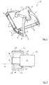
- FIG Fig. 2 A first embodiment of a protection device 12 which is attached to a transmission 14 is shown in FIG Fig. 2 shown in a cross-sectional view.
- the protective device 12 serves to undesirably escape from the transmission 14 leaking lubricant 28, such as lubricating oil, and thus keep away from the food products.
- the protective device 12 and the transmission 14 are in Fig. 2 shown in an actual installation position, ie, the protective device 12 and the transmission 14 are arranged one behind the other in the horizontal direction. Also the other figures ( FIG. 3 to FIG. 5 ) show the protective device 12 and the transmission 14 in each case in an actual possible installation position.
- the protective device 12 is circumferentially disposed about an output shaft 16 of the transmission 14, wherein the protective device 12 comprises a housing 18 which surrounds the output shaft 16.
- the output shaft 16 extends in the horizontal, ie horizontally.
- a circumferential recess 20 is introduced, which defines a reservoir 22.
- the housing 18 of the protective device 12 is attached directly to the gear 14 and to a side wall 24 b of the gear housing 24.
- the transmission housing 24 defines the reservoir 22 in regions with an end wall 24a and the side wall 24b.
- the output shaft 16 of the transmission 14 extends through the protective device 12 and exits from the housing 18 in the region of an outlet opening 26.
- the output shaft 16 may be formed longer than in the Fig. 2 shown.
- the lubricant 28 flows through its weight on the output shaft 16, the housing 18 and the gear housing 24 "down" and thus enters the reservoir 22nd
- the size of the reservoir 22 is designed so that all of the lubricant 28, which was initially present in the transmission housing 24, can be received by the reservoir 22.
- One such case is in Fig. 2 shown. It can be seen that the lubricant 28 can not leave the housing 18 or the reservoir 22 through the outlet opening 26. The level of the lubricant 28 thus does not reach an overflow line 27, which indicates in the figures when too much lubricant 28 is present in the reservoir 22.
- the lubricant 28 is permanently held in the reservoir 22, whereby contamination of food products can be prevented.
- Overflowing can be prevented, in particular, if the position of the transmission 14 and thus also the position of the protective device 12 are not at or around e.g. maximum 15 ° changes.
- a second embodiment is shown which differs from the first embodiment of Fig. 2 differs in that on the output shaft 16, a circumferential collar 30 is attached. A distance of the collar 30 from the output shaft 16 increases with increasing distance from the transmission 14.
- the transmission 14 also obliquely to the horizontal (ie in the in Fig. 3 shown position or overhead). at an overhead mounting, the transmission 14 is above the protective device 12.
- the collar 30 leaking lubricant 28 is led away from the output shaft 16 and deflected in the direction of the reservoir 22.
- the reservoir adjacent to the recess 20 is bounded by a recess 32.
- the indentation 32 is part of the housing 18 and extends parallel to the output shaft 16 to the transmission 14 out. By the end of the recess 32, the position of the overflow line 27 is defined.
- Fig. 4 shows a third embodiment of a protective device 12.
- the third embodiment is intended for horizontal installation.
- Compared to the first embodiment of Fig. 2 includes the transmission 14 according to Fig. 4 an output flange 34 to which a driven extension 36 is screwed with screws 40.
- the output extension 36 is held and supported by a sealed ball bearing 38.
- the housing 18 of the protective device 12 is screwed by means of additional screws 40 to the transmission housing 24.
- the reservoir 22 is again formed by the circumferential recess 20.
- the reservoir 22 is limited by the ball bearing 38.
- the size of the ball bearing 38 limits the reservoir 22 upwards and thus defines the position of the overflow line 27.
- the reservoir 22 is delimited by an end wall 24 a and a side wall 24 b of the transmission housing 24.
- the end wall 24a may be formed by a functional seal of the transmission 14.
- a circumferential around the gear housing 24 sealing ring 25 is also attached.
- an electrical sensor (not shown) is arranged, which indicates the presence of lubricant 28 in the reservoir 22.
- the sensor can be read out by means of an electrical connection 42.
- An outer contour 43 of the protective device 12 and the transmission 14 are identical at a front end in each case.
- the front end is facing away from a servomotor 44.
- the servomotor 44 is in operative connection with the transmission 14.
- a drive shaft 45 of the servomotor 44 is coupled to the transmission 14.
- FIG. 5 shown fourth embodiment of the protective device 12 includes an output extension 36 which is formed as an output shaft. This output extension 36 is screwed onto an output shaft 46 of the transmission 14.
- the fourth embodiment shown is designed for overhead installation.
- the output extension 36 comprises a bell-shaped bulge 48 which, with increasing distance from the transmission 14, extends further away from the output shaft 46 or an axis defined by the output shaft 46.
- the recess 20 is provided in a front end of the housing 18.
- the recess 20 defines the reservoir 22.
- the reservoir 22 surrounds the ball bearing 38.
- the upper end of the recess 20 defines the overflow line 27.
- Fig. 5 the reservoir 22 is completely filled with lubricant 28.
- the bell-shaped bulge 48 ends, wherein in a front end of the bulge 48, a circumferential semicircular recess 50 is provided which forms a drip edge 52.
- the reservoir 22 keeps the lubricant 28 permanently in the protection device 12, so that contamination of, for example, the food products can be prevented.
Landscapes
- Engineering & Computer Science (AREA)
- Robotics (AREA)
- Mechanical Engineering (AREA)
- General Details Of Gearings (AREA)
- Manipulator (AREA)
Priority Applications (1)
| Application Number | Priority Date | Filing Date | Title |
|---|---|---|---|
| EP16306052.8A EP3281753B1 (fr) | 2016-08-12 | 2016-08-12 | Robot |
Applications Claiming Priority (1)
| Application Number | Priority Date | Filing Date | Title |
|---|---|---|---|
| EP16306052.8A EP3281753B1 (fr) | 2016-08-12 | 2016-08-12 | Robot |
Publications (2)
| Publication Number | Publication Date |
|---|---|
| EP3281753A1 true EP3281753A1 (fr) | 2018-02-14 |
| EP3281753B1 EP3281753B1 (fr) | 2021-10-06 |
Family
ID=56855392
Family Applications (1)
| Application Number | Title | Priority Date | Filing Date |
|---|---|---|---|
| EP16306052.8A Active EP3281753B1 (fr) | 2016-08-12 | 2016-08-12 | Robot |
Country Status (1)
| Country | Link |
|---|---|
| EP (1) | EP3281753B1 (fr) |
Cited By (4)
| Publication number | Priority date | Publication date | Assignee | Title |
|---|---|---|---|---|
| DE102018101892A1 (de) * | 2018-01-29 | 2019-08-01 | Kiekert Ag | Kraftfahrzeugschloss |
| JP2019188575A (ja) * | 2018-04-27 | 2019-10-31 | ファナック株式会社 | パラレルリンクロボット |
| CN110421554A (zh) * | 2019-09-02 | 2019-11-08 | 西安安森智能机器人有限公司 | 一种巡检机器人传动装置 |
| CN114360633A (zh) * | 2020-10-13 | 2022-04-15 | 广东博智林机器人有限公司 | 检测器的防护装置 |
Citations (4)
| Publication number | Priority date | Publication date | Assignee | Title |
|---|---|---|---|---|
| JP2006138678A (ja) * | 2004-11-10 | 2006-06-01 | Sumitomo Chemical Co Ltd | オイル漏れ検知手段を具備する装置 |
| JP2009255194A (ja) * | 2008-04-14 | 2009-11-05 | Murata Mach Ltd | パラレルメカニズム |
| JP2013111694A (ja) * | 2011-11-29 | 2013-06-10 | Kawasaki Heavy Ind Ltd | 産業用ロボット |
| EP2829367A1 (fr) * | 2012-03-23 | 2015-01-28 | NTN Corporation | Dispositif d'actionnement d'articulation |
-
2016
- 2016-08-12 EP EP16306052.8A patent/EP3281753B1/fr active Active
Patent Citations (4)
| Publication number | Priority date | Publication date | Assignee | Title |
|---|---|---|---|---|
| JP2006138678A (ja) * | 2004-11-10 | 2006-06-01 | Sumitomo Chemical Co Ltd | オイル漏れ検知手段を具備する装置 |
| JP2009255194A (ja) * | 2008-04-14 | 2009-11-05 | Murata Mach Ltd | パラレルメカニズム |
| JP2013111694A (ja) * | 2011-11-29 | 2013-06-10 | Kawasaki Heavy Ind Ltd | 産業用ロボット |
| EP2829367A1 (fr) * | 2012-03-23 | 2015-01-28 | NTN Corporation | Dispositif d'actionnement d'articulation |
Cited By (7)
| Publication number | Priority date | Publication date | Assignee | Title |
|---|---|---|---|---|
| DE102018101892A1 (de) * | 2018-01-29 | 2019-08-01 | Kiekert Ag | Kraftfahrzeugschloss |
| JP2019188575A (ja) * | 2018-04-27 | 2019-10-31 | ファナック株式会社 | パラレルリンクロボット |
| CN110405728A (zh) * | 2018-04-27 | 2019-11-05 | 发那科株式会社 | 并联连杆机器人 |
| US11420343B2 (en) | 2018-04-27 | 2022-08-23 | Fanuc Corporation | Parallel link robot |
| CN110421554A (zh) * | 2019-09-02 | 2019-11-08 | 西安安森智能机器人有限公司 | 一种巡检机器人传动装置 |
| CN114360633A (zh) * | 2020-10-13 | 2022-04-15 | 广东博智林机器人有限公司 | 检测器的防护装置 |
| CN114360633B (zh) * | 2020-10-13 | 2023-06-06 | 广东博智林机器人有限公司 | 检测器的防护装置 |
Also Published As
| Publication number | Publication date |
|---|---|
| EP3281753B1 (fr) | 2021-10-06 |
Similar Documents
| Publication | Publication Date | Title |
|---|---|---|
| EP1423606B1 (fr) | Lubrification pour dispositif de reglage d'angle d'attaque sur une pale de rotor d'eolienne | |
| EP3281753B1 (fr) | Robot | |
| EP0231503B1 (fr) | Hélice à pas variable pour la propulsion d'un navire | |
| DE102014217223B4 (de) | Abdichtungssystem, Verfahren und Wasserfahrzeug | |
| EP2923120B1 (fr) | Adaptateur de couplage | |
| EP3517226B1 (fr) | Dispositif de nettoyage | |
| DE102013200356A1 (de) | Zusammengesetzter Dichtungsträger für ein Direktantriebs-Hauptlager einer Windkraftanlage | |
| DE60009577T2 (de) | Dosierpumpe zum fördern von flüssigkeiten | |
| WO2008113547A1 (fr) | Dispositif d'entraînement pour le fonctionnement en immersion au-dessous d'une surface de liquide | |
| DE102009000995A1 (de) | Schiffsantrieb mit einer Unterwasser verschwenkbaren Antriebseinheit | |
| EP3387298B1 (fr) | Joint d'étanchéité | |
| EP1666671B1 (fr) | Fraise pour paroi moulée | |
| DE102011108016A1 (de) | Selbstfahrender Oberflächenfräser | |
| DE3135037C2 (fr) | ||
| DE102019217534B4 (de) | Rotorlager für eine Windenergieanlage und Windenergieanlage | |
| DE4010769C2 (fr) | ||
| EP3377257B1 (fr) | Outil entraîné | |
| DE3828042C1 (en) | Adjusting device for the rotor blades of Kaplan turbines | |
| DE102011108962B4 (de) | Elektrischer Spindelantrieb | |
| DE19928450A1 (de) | Labyrinthdichtung, Gehäuse mit einer Labyrinthdichtung und Anordnung mit einem Gehäuse mit einer Labyrinthdichtung | |
| EP0111067A1 (fr) | Mélangeur conique à vis | |
| EP2721312B1 (fr) | Dispositif de palier pour arbres de vis transporteuse | |
| DE102004042745A1 (de) | Spindeltrieb für eine Spritzgiessmaschine mit einer Schmiervorrichtung | |
| DE8208046U1 (de) | Kreiselpumpenaggregat mit Spaltrohrmagnetkupplung | |
| EP3701091A1 (fr) | Engin spécial de génie civil, notamment fraiseuse à rideau souterrain |
Legal Events
| Date | Code | Title | Description |
|---|---|---|---|
| PUAI | Public reference made under article 153(3) epc to a published international application that has entered the european phase |
Free format text: ORIGINAL CODE: 0009012 |
|
| STAA | Information on the status of an ep patent application or granted ep patent |
Free format text: STATUS: THE APPLICATION HAS BEEN PUBLISHED |
|
| AK | Designated contracting states |
Kind code of ref document: A1 Designated state(s): AL AT BE BG CH CY CZ DE DK EE ES FI FR GB GR HR HU IE IS IT LI LT LU LV MC MK MT NL NO PL PT RO RS SE SI SK SM TR |
|
| AX | Request for extension of the european patent |
Extension state: BA ME |
|
| STAA | Information on the status of an ep patent application or granted ep patent |
Free format text: STATUS: REQUEST FOR EXAMINATION WAS MADE |
|
| 17P | Request for examination filed |
Effective date: 20180814 |
|
| RBV | Designated contracting states (corrected) |
Designated state(s): AL AT BE BG CH CY CZ DE DK EE ES FI FR GB GR HR HU IE IS IT LI LT LU LV MC MK MT NL NO PL PT RO RS SE SI SK SM TR |
|
| GRAP | Despatch of communication of intention to grant a patent |
Free format text: ORIGINAL CODE: EPIDOSNIGR1 |
|
| STAA | Information on the status of an ep patent application or granted ep patent |
Free format text: STATUS: GRANT OF PATENT IS INTENDED |
|
| INTG | Intention to grant announced |
Effective date: 20210519 |
|
| GRAS | Grant fee paid |
Free format text: ORIGINAL CODE: EPIDOSNIGR3 |
|
| GRAA | (expected) grant |
Free format text: ORIGINAL CODE: 0009210 |
|
| STAA | Information on the status of an ep patent application or granted ep patent |
Free format text: STATUS: THE PATENT HAS BEEN GRANTED |
|
| AK | Designated contracting states |
Kind code of ref document: B1 Designated state(s): AL AT BE BG CH CY CZ DE DK EE ES FI FR GB GR HR HU IE IS IT LI LT LU LV MC MK MT NL NO PL PT RO RS SE SI SK SM TR |
|
| REG | Reference to a national code |
Ref country code: GB Ref legal event code: FG4D Free format text: NOT ENGLISH |
|
| REG | Reference to a national code |
Ref country code: CH Ref legal event code: EP Ref country code: AT Ref legal event code: REF Ref document number: 1435819 Country of ref document: AT Kind code of ref document: T Effective date: 20211015 |
|
| REG | Reference to a national code |
Ref country code: DE Ref legal event code: R096 Ref document number: 502016013948 Country of ref document: DE |
|
| REG | Reference to a national code |
Ref country code: IE Ref legal event code: FG4D Free format text: LANGUAGE OF EP DOCUMENT: GERMAN |
|
| REG | Reference to a national code |
Ref country code: LT Ref legal event code: MG9D |
|
| REG | Reference to a national code |
Ref country code: NL Ref legal event code: MP Effective date: 20211006 |
|
| PG25 | Lapsed in a contracting state [announced via postgrant information from national office to epo] |
Ref country code: RS Free format text: LAPSE BECAUSE OF FAILURE TO SUBMIT A TRANSLATION OF THE DESCRIPTION OR TO PAY THE FEE WITHIN THE PRESCRIBED TIME-LIMIT Effective date: 20211006 Ref country code: LT Free format text: LAPSE BECAUSE OF FAILURE TO SUBMIT A TRANSLATION OF THE DESCRIPTION OR TO PAY THE FEE WITHIN THE PRESCRIBED TIME-LIMIT Effective date: 20211006 Ref country code: FI Free format text: LAPSE BECAUSE OF FAILURE TO SUBMIT A TRANSLATION OF THE DESCRIPTION OR TO PAY THE FEE WITHIN THE PRESCRIBED TIME-LIMIT Effective date: 20211006 Ref country code: BG Free format text: LAPSE BECAUSE OF FAILURE TO SUBMIT A TRANSLATION OF THE DESCRIPTION OR TO PAY THE FEE WITHIN THE PRESCRIBED TIME-LIMIT Effective date: 20220106 |
|
| PG25 | Lapsed in a contracting state [announced via postgrant information from national office to epo] |
Ref country code: IS Free format text: LAPSE BECAUSE OF FAILURE TO SUBMIT A TRANSLATION OF THE DESCRIPTION OR TO PAY THE FEE WITHIN THE PRESCRIBED TIME-LIMIT Effective date: 20220206 Ref country code: SE Free format text: LAPSE BECAUSE OF FAILURE TO SUBMIT A TRANSLATION OF THE DESCRIPTION OR TO PAY THE FEE WITHIN THE PRESCRIBED TIME-LIMIT Effective date: 20211006 Ref country code: PT Free format text: LAPSE BECAUSE OF FAILURE TO SUBMIT A TRANSLATION OF THE DESCRIPTION OR TO PAY THE FEE WITHIN THE PRESCRIBED TIME-LIMIT Effective date: 20220207 Ref country code: PL Free format text: LAPSE BECAUSE OF FAILURE TO SUBMIT A TRANSLATION OF THE DESCRIPTION OR TO PAY THE FEE WITHIN THE PRESCRIBED TIME-LIMIT Effective date: 20211006 Ref country code: NO Free format text: LAPSE BECAUSE OF FAILURE TO SUBMIT A TRANSLATION OF THE DESCRIPTION OR TO PAY THE FEE WITHIN THE PRESCRIBED TIME-LIMIT Effective date: 20220106 Ref country code: NL Free format text: LAPSE BECAUSE OF FAILURE TO SUBMIT A TRANSLATION OF THE DESCRIPTION OR TO PAY THE FEE WITHIN THE PRESCRIBED TIME-LIMIT Effective date: 20211006 Ref country code: LV Free format text: LAPSE BECAUSE OF FAILURE TO SUBMIT A TRANSLATION OF THE DESCRIPTION OR TO PAY THE FEE WITHIN THE PRESCRIBED TIME-LIMIT Effective date: 20211006 Ref country code: HR Free format text: LAPSE BECAUSE OF FAILURE TO SUBMIT A TRANSLATION OF THE DESCRIPTION OR TO PAY THE FEE WITHIN THE PRESCRIBED TIME-LIMIT Effective date: 20211006 Ref country code: GR Free format text: LAPSE BECAUSE OF FAILURE TO SUBMIT A TRANSLATION OF THE DESCRIPTION OR TO PAY THE FEE WITHIN THE PRESCRIBED TIME-LIMIT Effective date: 20220107 Ref country code: ES Free format text: LAPSE BECAUSE OF FAILURE TO SUBMIT A TRANSLATION OF THE DESCRIPTION OR TO PAY THE FEE WITHIN THE PRESCRIBED TIME-LIMIT Effective date: 20211006 |
|
| REG | Reference to a national code |
Ref country code: DE Ref legal event code: R097 Ref document number: 502016013948 Country of ref document: DE |
|
| PG25 | Lapsed in a contracting state [announced via postgrant information from national office to epo] |
Ref country code: SM Free format text: LAPSE BECAUSE OF FAILURE TO SUBMIT A TRANSLATION OF THE DESCRIPTION OR TO PAY THE FEE WITHIN THE PRESCRIBED TIME-LIMIT Effective date: 20211006 Ref country code: SK Free format text: LAPSE BECAUSE OF FAILURE TO SUBMIT A TRANSLATION OF THE DESCRIPTION OR TO PAY THE FEE WITHIN THE PRESCRIBED TIME-LIMIT Effective date: 20211006 Ref country code: RO Free format text: LAPSE BECAUSE OF FAILURE TO SUBMIT A TRANSLATION OF THE DESCRIPTION OR TO PAY THE FEE WITHIN THE PRESCRIBED TIME-LIMIT Effective date: 20211006 Ref country code: EE Free format text: LAPSE BECAUSE OF FAILURE TO SUBMIT A TRANSLATION OF THE DESCRIPTION OR TO PAY THE FEE WITHIN THE PRESCRIBED TIME-LIMIT Effective date: 20211006 Ref country code: DK Free format text: LAPSE BECAUSE OF FAILURE TO SUBMIT A TRANSLATION OF THE DESCRIPTION OR TO PAY THE FEE WITHIN THE PRESCRIBED TIME-LIMIT Effective date: 20211006 Ref country code: CZ Free format text: LAPSE BECAUSE OF FAILURE TO SUBMIT A TRANSLATION OF THE DESCRIPTION OR TO PAY THE FEE WITHIN THE PRESCRIBED TIME-LIMIT Effective date: 20211006 |
|
| PLBE | No opposition filed within time limit |
Free format text: ORIGINAL CODE: 0009261 |
|
| STAA | Information on the status of an ep patent application or granted ep patent |
Free format text: STATUS: NO OPPOSITION FILED WITHIN TIME LIMIT |
|
| 26N | No opposition filed |
Effective date: 20220707 |
|
| PG25 | Lapsed in a contracting state [announced via postgrant information from national office to epo] |
Ref country code: AL Free format text: LAPSE BECAUSE OF FAILURE TO SUBMIT A TRANSLATION OF THE DESCRIPTION OR TO PAY THE FEE WITHIN THE PRESCRIBED TIME-LIMIT Effective date: 20211006 |
|
| PG25 | Lapsed in a contracting state [announced via postgrant information from national office to epo] |
Ref country code: SI Free format text: LAPSE BECAUSE OF FAILURE TO SUBMIT A TRANSLATION OF THE DESCRIPTION OR TO PAY THE FEE WITHIN THE PRESCRIBED TIME-LIMIT Effective date: 20211006 |
|
| PG25 | Lapsed in a contracting state [announced via postgrant information from national office to epo] |
Ref country code: MC Free format text: LAPSE BECAUSE OF FAILURE TO SUBMIT A TRANSLATION OF THE DESCRIPTION OR TO PAY THE FEE WITHIN THE PRESCRIBED TIME-LIMIT Effective date: 20211006 |
|
| REG | Reference to a national code |
Ref country code: CH Ref legal event code: PL |
|
| GBPC | Gb: european patent ceased through non-payment of renewal fee |
Effective date: 20220812 |
|
| PG25 | Lapsed in a contracting state [announced via postgrant information from national office to epo] |
Ref country code: LU Free format text: LAPSE BECAUSE OF NON-PAYMENT OF DUE FEES Effective date: 20220812 Ref country code: LI Free format text: LAPSE BECAUSE OF NON-PAYMENT OF DUE FEES Effective date: 20220831 Ref country code: CH Free format text: LAPSE BECAUSE OF NON-PAYMENT OF DUE FEES Effective date: 20220831 |
|
| REG | Reference to a national code |
Ref country code: BE Ref legal event code: MM Effective date: 20220831 |
|
| PG25 | Lapsed in a contracting state [announced via postgrant information from national office to epo] |
Ref country code: IE Free format text: LAPSE BECAUSE OF NON-PAYMENT OF DUE FEES Effective date: 20220812 |
|
| PG25 | Lapsed in a contracting state [announced via postgrant information from national office to epo] |
Ref country code: BE Free format text: LAPSE BECAUSE OF NON-PAYMENT OF DUE FEES Effective date: 20220831 |
|
| REG | Reference to a national code |
Ref country code: AT Ref legal event code: MM01 Ref document number: 1435819 Country of ref document: AT Kind code of ref document: T Effective date: 20220812 |
|
| PG25 | Lapsed in a contracting state [announced via postgrant information from national office to epo] |
Ref country code: GB Free format text: LAPSE BECAUSE OF NON-PAYMENT OF DUE FEES Effective date: 20220812 Ref country code: AT Free format text: LAPSE BECAUSE OF NON-PAYMENT OF DUE FEES Effective date: 20220812 |
|
| PGFP | Annual fee paid to national office [announced via postgrant information from national office to epo] |
Ref country code: IT Payment date: 20230825 Year of fee payment: 8 |
|
| PGFP | Annual fee paid to national office [announced via postgrant information from national office to epo] |
Ref country code: FR Payment date: 20230825 Year of fee payment: 8 |
|
| PGFP | Annual fee paid to national office [announced via postgrant information from national office to epo] |
Ref country code: DE Payment date: 20231027 Year of fee payment: 8 |
|
| PG25 | Lapsed in a contracting state [announced via postgrant information from national office to epo] |
Ref country code: HU Free format text: LAPSE BECAUSE OF FAILURE TO SUBMIT A TRANSLATION OF THE DESCRIPTION OR TO PAY THE FEE WITHIN THE PRESCRIBED TIME-LIMIT; INVALID AB INITIO Effective date: 20160812 |
|
| PG25 | Lapsed in a contracting state [announced via postgrant information from national office to epo] |
Ref country code: CY Free format text: LAPSE BECAUSE OF FAILURE TO SUBMIT A TRANSLATION OF THE DESCRIPTION OR TO PAY THE FEE WITHIN THE PRESCRIBED TIME-LIMIT Effective date: 20211006 |