EP3281306B1 - Multiplex-detektorsignalverstärker - Google Patents
Multiplex-detektorsignalverstärker Download PDFInfo
- Publication number
- EP3281306B1 EP3281306B1 EP16777416.5A EP16777416A EP3281306B1 EP 3281306 B1 EP3281306 B1 EP 3281306B1 EP 16777416 A EP16777416 A EP 16777416A EP 3281306 B1 EP3281306 B1 EP 3281306B1
- Authority
- EP
- European Patent Office
- Prior art keywords
- circuit
- uplink
- downlink
- signal
- radio frequency
- Prior art date
- Legal status (The legal status is an assumption and is not a legal conclusion. Google has not performed a legal analysis and makes no representation as to the accuracy of the status listed.)
- Active
Links
Images


Classifications
-
- H—ELECTRICITY
- H04—ELECTRIC COMMUNICATION TECHNIQUE
- H04B—TRANSMISSION
- H04B1/00—Details of transmission systems, not covered by a single one of groups H04B3/00 - H04B13/00; Details of transmission systems not characterised by the medium used for transmission
- H04B1/38—Transceivers, i.e. devices in which transmitter and receiver form a structural unit and in which at least one part is used for functions of transmitting and receiving
- H04B1/40—Circuits
-
- H—ELECTRICITY
- H03—ELECTRONIC CIRCUITRY
- H03F—AMPLIFIERS
- H03F3/00—Amplifiers with only discharge tubes or only semiconductor devices as amplifying elements
- H03F3/189—High-frequency amplifiers, e.g. radio frequency amplifiers
- H03F3/19—High-frequency amplifiers, e.g. radio frequency amplifiers with semiconductor devices only
-
- H—ELECTRICITY
- H03—ELECTRONIC CIRCUITRY
- H03F—AMPLIFIERS
- H03F3/00—Amplifiers with only discharge tubes or only semiconductor devices as amplifying elements
- H03F3/20—Power amplifiers, e.g. Class B amplifiers, Class C amplifiers
- H03F3/21—Power amplifiers, e.g. Class B amplifiers, Class C amplifiers with semiconductor devices only
- H03F3/211—Power amplifiers, e.g. Class B amplifiers, Class C amplifiers with semiconductor devices only using a combination of several amplifiers
-
- H—ELECTRICITY
- H03—ELECTRONIC CIRCUITRY
- H03F—AMPLIFIERS
- H03F3/00—Amplifiers with only discharge tubes or only semiconductor devices as amplifying elements
- H03F3/20—Power amplifiers, e.g. Class B amplifiers, Class C amplifiers
- H03F3/24—Power amplifiers, e.g. Class B amplifiers, Class C amplifiers of transmitter output stages
- H03F3/245—Power amplifiers, e.g. Class B amplifiers, Class C amplifiers of transmitter output stages with semiconductor devices only
-
- H—ELECTRICITY
- H04—ELECTRIC COMMUNICATION TECHNIQUE
- H04B—TRANSMISSION
- H04B7/00—Radio transmission systems, i.e. using radiation field
- H04B7/14—Relay systems
- H04B7/15—Active relay systems
- H04B7/155—Ground-based stations
- H04B7/15528—Control of operation parameters of a relay station to exploit the physical medium
- H04B7/15542—Selecting at relay station its transmit and receive resources
-
- H—ELECTRICITY
- H03—ELECTRONIC CIRCUITRY
- H03F—AMPLIFIERS
- H03F2200/00—Indexing scheme relating to amplifiers
- H03F2200/451—Indexing scheme relating to amplifiers the amplifier being a radio frequency amplifier
-
- H—ELECTRICITY
- H03—ELECTRONIC CIRCUITRY
- H03F—AMPLIFIERS
- H03F2203/00—Indexing scheme relating to amplifiers with only discharge tubes or only semiconductor devices as amplifying elements covered by H03F3/00
- H03F2203/20—Indexing scheme relating to power amplifiers, e.g. Class B amplifiers, Class C amplifiers
- H03F2203/21—Indexing scheme relating to power amplifiers, e.g. Class B amplifiers, Class C amplifiers with semiconductor devices only
- H03F2203/211—Indexing scheme relating to power amplifiers, e.g. Class B amplifiers, Class C amplifiers with semiconductor devices only using a combination of several amplifiers
- H03F2203/21109—An input signal being distributed by switching to a plurality of paralleled power amplifiers
Definitions
- Uplink communications may refer to communications that originate at a wireless communication device (referred to hereinafter as “wireless device") and that are transmitted to an access point (e.g., base station, remote radio head, wireless router, etc.) associated with the wireless communication system.
- Downlink communications may refer to communications from the access point to the wireless device.
- a wireless device in a wireless communication system may be positioned such that it may not receive uplink and/or downlink communications from an access point at a desired power level.
- a user of the wireless device may employ a signal booster to boost the uplink and/or downlink communications.
- the invention provides a signal booster according to appended claim 1 and a method according to appended claim 6.
- each of the first uplink tap circuit, the second uplink tap circuit, the first downlink tap circuit, and the second downlink tap circuit include one or more of a resistor, a splitter, a capacitor, and a directional coupler.
- the uplink radio frequency detector circuit and the downlink radio frequency detector circuit each include one or more of a diode and a log detector.
- the invention further comprising a control unit coupled to the uplink switch circuit, the downlink switch circuit, the uplink radio frequency detector circuit, and the downlink radio frequency detector circuit, wherein the control unit is configured to control the uplink switch circuit and the downlink switch circuit, to receive a uplink output from the uplink radio frequency detector circuit, and to receive a downlink output from the downlink radio frequency detector circuit.
- control unit is configured to: adjust a first uplink amplification applied to the first uplink signal in the first uplink amplification path and a second uplink amplification applied to the second uplink signal in the second uplink amplification path based on the uplink output from the uplink radio frequency detector circuit, and adjust a first downlink amplification applied to the first downlink signal in the first downlink amplification path and a second downlink amplification applied to the second downlink signal in the second downlink amplification path based on the downlink output from the downlink radio frequency detector circuit.
- the first uplink signal and the first downlink signal are part of a same communication frequency band in the wireless communication network.
- decoupling the first-direction radio frequency detector from the first first-direction amplification path and coupling the first-direction radio frequency detector to the second first-direction amplification path occurs while the first, first-direction signal is amplified by the first first-direction amplification path.
- the method further comprising the steps of controlling the amplification of the first first-direction signal in the first first-direction amplification path based on the power level of the first first-direction signal; and controlling the amplification of the second first-direction signal in the second first-direction amplification path based on the power level of the second first-direction signal.
- a signal booster may include a first port and a second port.
- the first port may be coupled to an outside antenna that is configured to receive downlinks signals from a wireless communication access point, such as a base station or remote radio head, and to transmit uplink signals to a wireless communication access point.
- the second port may be coupled to an inside antenna that is configured to receive uplink signals from a wireless device, such as a cellular phone or tablet, and to transmit downlink signals to the wireless device.
- the signal booster may include a first amplification path that includes a first tap circuit.
- the first amplification path may be coupled between the first port and the second port and may be configured to amplify the downlink signals.
- the signal booster may further include a second amplification path that includes a second tap circuit.
- the second amplification path may be coupled between the first port and the second port and may be configured to amplify the uplink signals.
- the signal booster may further include a radio frequency detector circuit and a switch circuit coupled to the first tap circuit, to the second tap circuit, and to the radio frequency detector circuit.
- the switch circuit may be configured to switch between coupling the radio frequency detector circuit to the first tap circuit and coupling the radio frequency detector circuit to the second tap circuit to provide either a portion of the downlink signal or a portion of the uplink signal to the radio frequency detector.
- the radio frequency detector may provide an indication of the strength of the downlink signal and the strength of the uplink signal to a control unit.
- the control unit may be configured to control the amplification applied by the first and second amplification paths to the downlink and uplink signals, respectively.
- the signal booster may adjust the amplification of the downlink and uplink signals for any reasons, such as to reduce antenna-to-antenna and internal oscillations, to boost signal strength, to reduce a noise floor at the wireless communication access point, among other reasons.
- the signal booster may reduce a number of radio frequency detector circuits in the signal booster. Reducing the number of radio frequency detector circuits may reduce cost, decrease size, and may provide other benefits as well.
- FIG. 1 illustrates an example wireless communication system 100 (referred to hereinafter as "system 100"), arranged in accordance with at least some embodiments described in this disclosure.
- the system 100 may be configured to provide wireless communication services to wireless devices, such as a wireless device 106 via an access point 104.
- the system 100 may further include a bidirectional signal booster 102 (referred to hereinafter as “the signal booster 102").
- the signal booster 102 may be any suitable system, device, or apparatus configured to receive wireless signals (e.g., radio frequency (RF) signals communicated in one or more frequency bands) communicated between the access point 104 and the wireless device 106.
- RF radio frequency
- the signal booster 102 may be configured to amplify, mute, repeat, filter, and/or otherwise process the received wireless signals and may be configured to re-transmit the processed wireless signals.
- the system 100 may include any number of access points 104 configured to provide wireless communication services to any number of wireless devices 106.
- the signal booster 102 may communicated wireless signals from multiple access points 104 to multiple different wireless devices 106, from a single access point 104 to multiple different wireless devices 106, or from multiple access points 104 to one wireless device 106.
- the wireless communication services provided by the system 100 may include voice services, data services, messaging services, and/or any suitable combination thereof.
- the system 100 may include a Frequency Division Duplexing (FDD) network, a Frequency Division Multiple Access (FDMA) network, an Orthogonal FDMA (OFDMA) network, a Code Division Multiple Access (CDMA) network, a Time Division Multiple Access (TDMA) network, a Direct Sequence Spread Spectrum (DSSS) network, a Frequency Hopping Spread Spectrum (FHSS) network, and/or some other wireless communication network.
- FDD Frequency Division Duplexing
- FDMA Frequency Division Multiple Access
- OFDMA Orthogonal FDMA
- CDMA Code Division Multiple Access
- TDMA Time Division Multiple Access
- DSSS Direct Sequence Spread Spectrum
- FHSS Frequency Hopping Spread Spectrum
- the system 100 maybe configured to operate as a second generation (2G) wireless communication network, a third generation (3G) wireless communication network, a fourth generation (4G) wireless communication network, a Wi-Fi network, or some other communication network.
- the system 100 may be configured to operate as a Long Term Evolution (LTE) or LTE Advanced wireless communication network.
- LTE Long Term Evolution
- the access point 104 may be any suitable wireless network communication point and may include, by way of example but not limitation, a base station, a remote radio head (RRH), a satellite, a wireless router, or any other suitable communication point.
- the wireless device 106 may be any device that may use the system 100 to obtain wireless communication services and may include, by way of example and not limitation, mobile access terminals, such as a cellular phone, a smartphone, a personal data assistant (PDA), a laptop computer, a tablet computer, among others; non-mobile access terminals, such as a personal computer, a wireless router, a modem, among others; or any other similar device configured to communicate within the system 100.
- mobile access terminals such as a cellular phone, a smartphone, a personal data assistant (PDA), a laptop computer, a tablet computer, among others
- non-mobile access terminals such as a personal computer, a wireless router, a modem, among others; or any other similar device configured to communicate within the system 100.
- the wireless signals may be affected during the propagation such that, in some instances, the wireless signals may be substantially degraded.
- the signal degradation may result in the access point 104 or the wireless device 106 not receiving, detecting, or decoding information from the wireless signals. Therefore, the signal booster 102 may be configured to increase the power of and/or improve the signal quality of the wireless signals such that the communication of the wireless signals between the access point 104 and the wireless device 106 may be improved.
- the signal booster 102 may receive a wireless signal communicated between the access point 104 and the wireless device 106 and may convert the wireless signal into an electrical signal (e.g., via an antenna).
- the signal booster 102 may be configured to amplify the electrical signal and the amplified electrical signal may be converted into an amplified wireless signal (e.g., via an antenna) that may be transmitted.
- the signal booster 102 may amplify the electrical signal by applying a gain to the electrical signal.
- the gain may be a set gain or a variable gain, and may be less than, equal to, or greater than one. Therefore, in the present disclosure, the term "amplify" may refer to applying any gain to a wireless signal including gains that are less than one.
- the signal booster 102 may adjust the gain based on conditions associated with communicating the wireless signals (e.g., providing noise floor protection in the system 100, internal oscillation of the signal booster 102, external oscillation (e.g., antenna to antenna oscillations) of the signal booster 102, and/or overload protection at the access point 104). In these and other embodiments, the signal booster 102 may adjust the gain in real time. The signal booster 102 may also filter out noise associated with the received wireless signal such that the retransmitted wireless signal may be a cleaner signal than the received wireless signal. Therefore, the signal booster 102 may improve the communication of wireless signals between the access point 104 and the wireless device 106.
- the signal booster 102 may adjust the gain based on conditions associated with communicating the wireless signals (e.g., providing noise floor protection in the system 100, internal oscillation of the signal booster 102, external oscillation (e.g., antenna to antenna oscillations) of the signal booster 102, and/or overload protection at the access point 104). In these and other embodiments, the signal booster
- the wireless device 106 may communicate a wireless uplink signal 112 intended for reception by the access point 104 and a first antenna 108 may be configured to receive the wireless uplink signal 112.
- the first antenna 108 may be configured to convert the received wireless uplink signal 112 into an electrical uplink signal.
- the first antenna 108 may be communicatively coupled to a first interface port (not expressly depicted in FIG. 1 ) of the signal booster 102 such that the signal booster 102 may receive the electrical uplink signal from the first antenna 108 at the first interface port.
- An interface port may be any suitable port configured to interface the signal booster 102 with another device (e.g., an antenna, a modem, another signal booster, etc.) through a wired connection from which the signal booster 102 may receive a signal and/or to which the signal booster 102 may communicate a signal.
- another device e.g., an antenna, a modem, another signal booster, etc.
- the signal booster 102 may be configured to apply a gain to the electrical uplink signal to amplify the electrical uplink signal.
- the signal booster 102 may direct the amplified electrical uplink signal toward a second interface port (not expressly depicted in FIG. 1 ) of the signal booster 102 that may be communicatively coupled to a second antenna 110.
- the second antenna 110 may be configured to receive the amplified electrical uplink signal from the second interface port and may convert the amplified electrical uplink signal into an amplified wireless uplink signal 114 that may also be transmitted by the second antenna 110.
- the amplified wireless uplink signal 114 may then be received by the access point 104.
- the signal booster 102 may also be configured to filter the electrical uplink signal to remove at least some noise associated with the received wireless uplink signal 112. Consequently, the amplified wireless uplink signal 114 may have a better signal-to-noise ratio (SNR) than the wireless uplink signal 112 that may be received by the first antenna 108. Accordingly, the signal booster 102 may be configured to improve the communication of uplink signals between the access point 104 and the wireless device 106.
- uplink signal without specifying wireless or electrical uplink signals, may refer to wireless uplink signals or electrical uplink signals.
- uplink signal may include uplink signals between the access point 104 and the signal booster 102 and between the signal booster 102 and the wireless device 106. Furthermore, in some embodiments, uplink signals may be referred to as first direction signals.
- the access point 104 may communicate a wireless downlink signal 116 intended for the wireless device 106 and the second antenna 110 may be configured to receive the wireless downlink signal 116.
- the second antenna 110 may convert the received wireless downlink signal 116 into an electrical downlink signal such that the electrical downlink signal may be received at the second interface port of the signal booster 102.
- the signal booster 102 may be configured to apply a gain to the electrical downlink signal to amplify the electrical downlink signal.
- the signal booster 102 may also be configured to direct the amplified electrical downlink signal toward the first interface port of the signal booster 102 such that the first antenna 108 may receive the amplified electrical downlink signal.
- the first antenna 108 may be configured to convert the amplified electrical downlink signal into an amplified wireless downlink signal 118 that may also be transmitted by the first antenna 108.
- the amplified wireless downlink signal 118 may then be received by the wireless device 106.
- the signal booster 102 may also be configured to filter the electrical downlink signal to remove at least some noise associated with the received wireless downlink signal 116. Therefore, the amplified wireless downlink signal 118 may have a better SNR than the wireless downlink signal 116 received by the second antenna 110. Accordingly, the signal booster 102 may also be configured to improve the communication of downlink signals, which may be second direction signals, between the access point 104 and the wireless device 106.
- downlink signals without specifying wireless or electrical downlink signals
- the use of the term "downlink signal” without specifying may include downlink signals between the access point 104 and the signal booster 102 and between the signal booster 102 and the wireless device 106.
- downlink signals may be referred to as second direction signals.
- the distance between the signal booster 102 and the wireless device 106 may be relatively close as compared to the distance between the signal booster 102 and the access point 104.
- the system 100 may include any number of signal boosters 102, access points 104, and/or wireless devices 106.
- the signal booster 102 may be coupled to multiple antennas, like the first antenna 108, that are configured to communicate with wireless devices.
- the signal booster 102 may be included in a cradle configured to hold the wireless device 106.
- the signal booster 102 may be configured to communicate with the wireless device 106 via wired communications (e.g., using electrical signals communicated over a wire) instead of wireless communications (e.g., via wireless signals).
- the signal booster 102 is illustrated and described with respect to performing operations with respect to wireless communications such as receiving and transmitting wireless signals via the first antenna 108 and the second antenna 110, the scope of the present disclosure is not limited to such applications.
- the signal booster 102 (or other signal boosters described herein) may be configured to perform similar operations with respect to communications that are not necessarily wireless, such as processing signals that may be received and/or transmitted via one or more modems or other signal boosters communicatively coupled to the interface ports of the signal booster 102 via a wired connection.
- the signal booster 102 may be configured to perform operations on multiple different frequency communication bands.
- the communication spectrum for wireless communications may include multiple bands that include uplink channels and downlink channels.
- the signal booster 102 may operate to boost uplink and downlink signals throughout the channels of multiple frequency bands simultaneously.
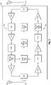
- FIG. 2 illustrates an example signal booster 200 with a multiplex detector, arranged in accordance with at least some embodiments described in this disclosure.
- the signal booster 200 may be part of a wireless communication system, such as the wireless communication system 100 illustrated in FIG. 1 and may operate in a similar manner as the signal booster 102 of FIG. 1 .
- the signal booster 200 may include a first interface port 203 and a second interface port 207.
- the first interface port 203 may be coupled to a first antenna 204.
- the first antenna 204 may be configured to receive downlink signals from a wireless communication access point and to transmit uplink signals to the wireless communication access point.
- the second interface port 207 may be coupled to a second antenna 208.
- the second antenna 208 may be configured to receive uplink signals from a wireless device and to transmit downlink signals to the wireless device.
- the signal booster 200 may also include a first duplexer 202 coupled to the first interface port 203 and a second duplexer 206 coupled to the second interface port.
- the signal booster 200 may further include a downlink amplification path 210 coupled between the first and second duplexers 202 and 206 and an uplink amplification path 220 coupled between the first and second duplexers 202 and 206.
- the signal booster 200 may further include a switch circuit 230, a radio frequency detector circuit 240 (referred to herein as the RF detector circuit 240), and a control unit 250.
- the switch circuit 230 and the RF detector circuit 240 together may be referred to as a multiplex detector.
- the downlink amplification path 210 may include a first downlink amplifier circuit 212a, a first downlink filter circuit 214a, a second downlink amplifier circuit 212b, a second downlink filter circuit 214b, a first tap circuit 216, and a third downlink amplifier circuit 212c.
- the first downlink amplifier circuit 212a, the second downlink amplifier circuit 212b, and third downlink amplifier circuit 212c may be referred to herein as the downlink amplifier circuits 212.
- Each of the downlink amplifier circuits 212 may include one or more power amplifiers, low noise amplifiers, digital or analog attenuators, among other attenuation or amplification circuits or devices.
- Each of the downlink amplifier circuits 212 may be configured to apply an amplification to a downlink signal passing through the signal booster 200.
- the amplification may be one or greater or less than one.
- an amplification of one or more of the downlink amplifier circuits 212 may be variable.
- the gain of the one or more of the downlink amplifier circuits 212 that is variable may be controlled by the control unit 250.
- the first downlink filter circuit 214a and the second downlink filter circuit 214b may each include one or more low pass, high pass, or band pass filters configured to pass frequencies to be amplified or attenuated by the signal booster 200 and filter out other frequencies.
- the first downlink amplifier circuit 212a may be coupled to the output of the first duplexer 202.
- the first downlink filter circuit 214a may be coupled to the output of the first downlink amplifier circuit 212a.
- the second downlink amplifier circuit 212b may be coupled to the output of the first downlink filter circuit 214a.
- the second downlink filter circuit 214b may be coupled to the output of the second downlink amplifier circuit 212b.
- the first tap circuit 216 may be coupled to the output of the second downlink filter circuit 214b.
- the third downlink amplifier circuit 212c may be coupled to the first tap circuit 216.
- the first tap circuit 216 may be coupled to the switch circuit 230.
- the first tap circuit 216 may be configured to divert a portion of a downlink signal in the downlink amplification path 210 toward the switch circuit 230.
- the first tap circuit 216 may be further configured to pass the remaining portion of the downlink signal to the third downlink amplifier circuit 212c for amplification.
- the first tap circuit 216 may include a resistor, a splitter, a capacitor, a directional coupler, or some other circuit or circuit component.
- the uplink amplification path 220 may include a first uplink amplifier circuit 222a, a first uplink filter circuit 224a, a second uplink amplifier circuit 222b, a second uplink filter circuit 224b, a second tap circuit 226, and a third uplink amplifier circuit 222c.
- the first uplink amplifier circuit 222a, the second uplink amplifier circuit 222b, and third uplink amplifier circuit 222c may be referred to herein as the uplink amplifier circuits 222.
- Each of the uplink amplifier circuits 222 may include one or more power amplifiers, low noise amplifiers, digital or analog attenuators, among other attenuation or amplification circuits or devices.
- Each of the uplink amplifier circuits 222 may be configured to apply an amplification to an uplink signal passing through the signal booster 200. In these and other embodiments, the amplification may be one or greater or less than one. In some embodiments, an amplification of one or more of the uplink amplifier circuits 222 may be variable. In these and other embodiments, the gain of the one or more of the uplink amplifier circuits 222 that is variable may be controlled by the control unit 250.
- the first uplink filter circuit 224a and the second uplink filter circuit 224b may each include one or more low pass, high pass, or band pass filters configured to pass frequencies to be amplified or attenuated by the signal booster 200 and filter out other frequencies.
- the first uplink amplifier circuit 222a may be coupled to the output of the first duplexer 202.
- the first uplink filter circuit 224a may be coupled to the output of the first uplink amplifier circuit 222a.
- the second uplink amplifier circuit 222b may be coupled to the output of the first uplink filter circuit 224a.
- the second uplink filter circuit 224b may be coupled to the output of the second uplink amplifier circuit 222b.
- the second tap circuit 226 may be coupled to the output of the second uplink filter circuit 224b.
- the third uplink amplifier circuit 222c may be coupled to the second tap circuit 226.
- the second tap circuit 226 may be coupled to the switch circuit 230.
- the second tap circuit 226 may be configured to divert a portion of an uplink signal in the uplink amplification path 220 toward the switch circuit 230.
- the second tap circuit 226 may be further configured to pass the remaining portion of the uplink signal to the third uplink amplifier circuit 222c for amplification.
- the second tap circuit 226 may include a resistor, a splitter, a capacitor, a directional coupler, or some other circuit or circuit component.
- the first and second tap circuits 216 and 226 may include the same components or different components.
- the switch circuit 230 may be coupled to the first tap circuit 216, the second tap circuit 226, and the RF detector circuit 240.
- the switch circuit 230 may be configured to switch between electrically coupling the RF detector circuit 240 to the first tap circuit 216 and electrically coupling the RF detector circuit 240 to the second tap circuit 226 to provide either a portion of the downlink signal or a portion of the uplink signal to the RF detector circuit 240.
- the switch circuit 230 may electrically couple the first and second tap circuits 216 and 226 to the RF detector circuit 240 for equal alternating periods. Alternately or additionally, the switch circuit 230 may couple the first and second tap circuits 216 and 226 to the RF detector circuit 240 for unequal alternating periods, random periods, or following some other sequence.
- the switch circuit 230 may continue to receive a portion of the uplink and downlink signals from the first and second tap circuits 216 and 226 even when the first and second tap circuits 216 and 226 are not electrically coupled to the RF detector circuit 240.
- the switch circuit 230 may isolate the portion of the uplink signal from the RF detector circuit 240 and from the downlink amplification path 210.
- the switch circuit 230 may ground the uplink or downlink signal not being passed to the RF detector circuit 240. In some embodiments, the switch circuit 230 may include a tri-state. In the tri-state, the switch circuit 230 may not electrically couple either one of the first and second tap circuits 216 and 226 to the RF detector circuit 240.
- the switch circuit 230 may be controlled by the control unit 250. In these and other embodiments, the switch circuit 230 may couple the RF detector circuit 240 to one of the first and second tap circuits 216 and 226 based on a command from the control unit 250.
- the RF detector circuit 240 may be coupled to the control unit 250 and the switch circuit 230 and configured to receive a portion of a downlink signal from the first tap circuit 216 and a portion of an uplink signal from the second tap circuit 226. In some embodiments, the RF detector circuit 240 may not receive the portion of the downlink signal from the first tap circuit 216 and the portion of the uplink signal from the second tap circuit 226 at the same time but at different times. In these and other embodiments, the RF detector circuit 240 may be configured to detect a power level of the portions of the downlink and uplink signals. The RF detector circuit 240 may provide the detected power levels to the control unit 250. In some embodiments, the RF detector circuit 240 may include a diode, a log detector, or some other radio frequency detection circuit components.
- the control unit 250 may be configured to receive the detected power levels of the downlink and uplink signals in the signal booster 200. Based on the detected power levels of the downlink signals, the control unit 250 may adjust an amplification applied to the downlink signal in the downlink amplification path 210. For example, the control unit 250 may be configured to adjust the amplification in one or more of the downlink amplification circuits 212.
- the control unit 250 may adjust an amplification applied to the uplink signal in the uplink amplification path 220.
- the control unit 250 may be configured to adjust the amplification in one or more of the uplink amplifier circuits 222.
- the control unit 250 may adjust the amplification in the uplink and downlink amplification paths 210 and 220 independently using information from the single RF detector circuit 240.
- control unit 250 may adjust the amplification in the uplink and downlink amplification paths 210 and 220 as part of a feedback control loop that uses the single RF detector circuit 240. For example, the control unit 250 may adjust the amplification in the first uplink amplifier circuit 222a, receive an indication of the power level of the uplink signal from the RF detector circuit 240 by way of the second tap circuit 226 and the switch circuit 230. Based on the indication of the power level after adjusting the amplification, the control unit 250 may further adjust the amplification applied to the uplink signal.
- control unit 250 may adjust the amplification in the uplink and downlink amplification paths 210 and 220 based on configurations of the wireless communication network in which the signal booster 200 is operating.
- the signal booster 200 may operate to increase or decrease an amplification applied to the uplink and downlink signals based on noise levels at an access point, government regulations, and wireless communication operator regulations, among others.
- the signal booster 200 may apply any known algorithm or scheme to apply amplification to downlink and uplink signals to enhance or otherwise make communications between the wireless device and the access point function within the constraints of the wireless communications network in which the signal booster 200 is operating.
- 8,583,034 describes adjusting amplifications in uplink and downlink amplification paths in a signal booster in a wireless network to provide noise floor, internal oscillation, external oscillation (e.g., port-to-port oscillations), and/or overload protection for a wireless network.
- Downlink signals may be received by the first antenna 204 from an access point and provided to the downlink amplification path 210.
- the downlink amplification path 210 may apply filtering and an amplification to the downlink signals based on the characteristics of the wireless communication network in which the signal booster 200 is operating.
- the first tap circuit 216 may provide a portion of the downlink signals to the switch circuit 230.
- the switch circuit 230 may be electrically coupling the first tap circuit 216 with the RF detector circuit 240.
- the portion of the downlink signals may be provided to the RF detector circuit 240.
- the RF detector circuit 240 may provide a power level of the downlink signals to the control unit 250.
- the control unit 250 may adjust the amplification applied by the downlink amplification path 210 accordingly.
- Uplink signals may be received by the second antenna 208 from a wireless device and provided to the uplink amplification path 220.
- the uplink amplification path 220 may apply filtering and an amplification to the uplink signals based on the characteristics of the wireless communication network in which the signal booster 200 is operating.
- the second tap circuit 226 may provide a portion of the uplink signals to the switch circuit 230.
- the switch circuit 230 may be electrically coupling the first tap circuit 216 with the RF detector circuit 240. Thus, the portion of the uplink signals may not be provided to the RF detector circuit 240.
- the switch circuit 230 may disconnect the first tap circuit 216 and the RF detector circuit 240 and electrically couple the second tap circuit 226 with the RF detector circuit 240, such that the portion of the uplink signals may be provided to the RF detector circuit 240.
- the RF detector circuit 240 may provide a power level of the uplink signals to the control unit 250.
- the control unit 250 may adjust the amplification applied by the uplink amplification path 220 accordingly.
- the switch circuit 230 may switch between electrically coupling the first tap circuit 216 with the RF detector circuit 240 and electrically coupling the second tap circuit 226 with the RF detector circuit 240, periodically. In some embodiments, the switch circuit 230 may switch periodically at regular or irregular intervals. For example, in some embodiments the switch circuit 230 may switch between electrically coupling the first tap circuit 216 with the RF detector circuit 240 and electrically coupling the second tap circuit 226 with the RF detector circuit 240 every 0.1, 1, 10, 20 , 50, 100, or 500 milliseconds or at some other interval.
- the signal booster 200 may include additional interface ports that are coupled to antennas that are configured to communicate with wireless devices.
- the signal booster 200 may include multiple downlink and uplink amplification paths that are each configured to carry signals of different frequency bands of a wireless communication network.
- the downlink and uplink amplifications paths 210 and 220 may include a different number or order of the amplification and filtering circuits than illustrated and described.
- the first and second tap circuits 216 and 226 may be positioned in different locations within the downlink and uplink amplifications paths 210 and 220, respectively.
- FIG. 3 illustrates another example signal booster 300 with a multiplex detector, arranged in accordance with at least some embodiments described in this disclosure.
- the signal booster 300 may be part of a wireless communication system, such as the wireless communication system 100 illustrated in FIG. 1 and may operate in a similar manner as the signal booster 102 of FIG. 1 .
- the signal booster 300 may include a first interface port 303 and a second interface port 307.
- the first interface port 303 may be coupled to a first antenna 304.
- the first antenna 304 may be configured to receive downlink signals from a wireless communication access point and to transmit uplink signals to the wireless communication access point.
- the second interface port 307 may be coupled to a second antenna 308.
- the second antenna 308 may be configured to receive uplink signals from a wireless device and to transmit downlink signal to the wireless device.
- the signal booster 300 may also include a first duplexer 302 coupled to the first interface port 303 and a second duplexer 306 coupled to the second interface port.
- the signal booster 300 may further include a downlink amplification path 310 coupled between the first and second duplexers 302 and 306 and an uplink amplification path 320 coupled between the first and second duplexers 302 and 306.
- the signal booster 300 may further include a first switch circuit 330, a second switch circuit 332, a third switch circuit 334, a radio frequency detector circuit 340 (referred to herein as the RF detector circuit 340), and a control unit 350.
- the downlink amplification path 310 may include a downlink amplifier circuit 312 and a first tap circuit 316.
- the downlink amplifier circuit 312 and the first tap circuit 316 may operate in a similar manner as the downlink amplifier circuits 212 and the first tap circuit 216 of FIG. 2 .
- the downlink amplification path 310 may include multiple downlink amplifier circuits and filter circuits similar to the downlink amplification path 210 of FIG. 2 .
- the uplink amplification path 320 may include an uplink amplifier circuit 322 and a second tap circuit 326.
- the uplink amplifier circuit 322 and the second tap circuit 326 may operate in a similar manner the uplink amplifier circuits 222 and the second tap circuit 226 of FIG. 2 .
- the uplink amplification path 320 may include multiple downlink amplifier circuits and filter circuits similar to the uplink amplification path 220 of FIG. 2 .
- the first switch circuit 330 may be coupled between the first tap circuit 316 and the third switch circuit 334.
- the first switch circuit 330 may be configured to electrically couple and decouple the first tap circuit 316 from the third switch circuit 334.
- the first switch circuit 330 When the first switch circuit 330 is electrically coupling the first tap circuit 316 and the third switch circuit 334, the first switch circuit 330 may be referred to as closed.
- the first switch circuit 330 When the first switch circuit 330 is not electrically coupling the first tap circuit 316 and the third switch circuit 334, the first switch circuit 330 may be referred to as open.
- the first switch circuit 330 may be configured to pass a portion of a downlink signal from the first tap circuit 316 to the third switch circuit 334 when the first switch circuit 330 is electrically coupling the first tap circuit 316 to the third switch circuit 334. Likewise, the first switch circuit 330 may be configured to not pass a portion of a downlink signal from the first tap circuit 316 to the third switch circuit 334 when the first switch circuit 330 is not electrically coupling the first tap circuit 316 to the third switch circuit 334. The first switch circuit 330 may continue to receive the portion of the downlink signal from the first tap circuit 316 even when the first tap circuit 316 is decoupled from the third switch circuit 334. In these and other embodiments, the first switch circuit 330 may ground the portion of the downlink signal.
- the first switch circuit 330 may be controlled by the control unit 350. In these and other embodiments, the first switch circuit 330 may electrically couple and decouple the first tap circuit 316 from the third switch circuit 334 based on communications from the control unit 350.
- the second switch circuit 332 may be coupled between the second tap circuit 326 and the third switch circuit 334.
- the second switch circuit 332 may be configured to electrically couple and decouple the second tap circuit 326 from the third switch circuit 334.
- the second switch circuit 332 When the second switch circuit 332 is electrically coupling the second tap circuit 326 and the third switch circuit 334, the second switch circuit 332 may be referred to as closed.
- the second switch circuit 332 When the second switch circuit 332 is not electrically coupling the second tap circuit 326 and the third switch circuit 334, the second switch circuit 332 may be referred to as open.
- the second switch circuit 332 may be configured to pass a portion of an uplink signal from the second tap circuit 326 to the third switch circuit 334 when the second switch circuit 332 is electrically coupling the second tap circuit 326 to the third switch circuit 334. Likewise, the second switch circuit 332 may be configured to not pass a portion of an uplink signal from the second tap circuit 326 to the third switch circuit 334 when the second switch circuit 332 is not electrically coupling the second tap circuit 326 to the third switch circuit 334. The second switch circuit 332 may continue to receive the portion of the uplink signal from the second tap circuit 326 even when the second tap circuit 326 is decoupled from the third switch circuit 334. In these and other embodiments, the second switch circuit 332 may ground the portion of the uplink signal.
- the second switch circuit 332 may be controlled by the control unit 350. In these and other embodiments, the second switch circuit 332 may electrically couple and decouple the second tap circuit 326 from the third switch circuit 334 based on communications from the control unit 350.
- the third switch circuit 334 may be coupled to the first switch circuit 330, the second switch circuit 332, and the RF detector circuit 340.
- the third switch circuit 334 may be configured to switch between coupling the RF detector circuit 340 to the first switch circuit 330 and electrically coupling the RF detector circuit 340 to the second switch circuit 332.
- the third switch circuit 334 may electrically couple the first switch circuit 330 and the RF detector circuit 340 to provide the portion of the downlink signal to the RF detector circuit 340.
- the third switch circuit 334 may electrically couple the second switch circuit 332 and the RF detector circuit 340 to provide the portion of the uplink signal to the RF detector circuit 340.
- the RF detector circuit 340 may be coupled to the control unit 350 and the third switch circuit 334 and configured to receive a portion of a downlink signal from the first tap circuit 316 and a portion of an uplink signal from the second tap circuit 326. In these and other embodiments, the RF detector circuit 340 may be configured to detect a power level of the portions of the downlink and uplink signals. The RF detector circuit 340 may provide the detected power levels to the control unit 350. In some embodiments, the RF detector circuit 340 may include a diode, a log detector, or some other radio frequency detection circuit components.
- the control unit 350 may be configured to receive the detected power levels of the downlink and uplink signals in the signal booster 300. Based on the detected power levels of the downlink signals, the control unit 350 may adjust an amplification gain applied to the downlink signal in the downlink amplification path 310. Based on the detected power levels of the uplink signals, the control unit 350 may adjust an amplification applied to the uplink signal in the uplink amplification path 320. In some embodiments, the control unit 350 may adjust an amplification applied to the uplink and downlink signals in analogous manner as the control unit 250 adjusts amplification in the signal booster 200 in FIG. 2 .
- control unit 350 may be implemented by any suitable mechanism, such as a program, software, function, library, software as a service, analog, or digital circuitry, or any combination thereof.
- the control unit 350 may include a processor and memory.
- the processor may include, for example, a microprocessor, microcontroller, digital signal processor (DSP), application-specific integrated circuit (ASIC), a Field-Programmable Gate Array (FPGA), or any other digital or analog circuitry configured to interpret and/or to execute program instructions and/or to process data.
- the processor may interpret and/or execute program instructions and/or process data stored in the memory.
- the memory may include any suitable computer-readable media configured to retain program instructions and/or data for a period of time.
- computer-readable media may include tangible and/or non-transitory computer-readable storage media including Random Access Memory (RAM), Read-Only Memory (ROM), Electrically Erasable Programmable Read-Only Memory (EEPROM), Compact Disc Read-Only Memory (CD-ROM) or other optical disk storage, magnetic disk storage or other magnetic storage devices, flash memory devices (e.g., solid state memory devices), or any other storage medium which may be used to carry or store desired program code in the form of computer-executable instructions or data structures and which may be accessed by a general-purpose or special-purpose computer.
- RAM Random Access Memory
- ROM Read-Only Memory
- EEPROM Electrically Erasable Programmable Read-Only Memory
- CD-ROM Compact Disc Read-Only Memory
- flash memory devices e.g., solid state memory devices
- Computer-executable instructions may include, for example, instructions and data that cause a general-purpose computer, special-purpose computer, or special-purpose processing device to perform a certain function or group of functions.
- control unit 350 may be configured to control the first switch circuit 330 such that the first switch circuit 330 is only closed when the third switch circuit 334 is electrically coupling the first switch circuit 330 and the RF detector circuit 340.
- the first switch circuit 330 may be open until after the third switch circuit 334 electrically couples the first switch circuit 330 and the RF detector circuit 340.
- the first switch circuit 330 may also open before the third switch circuit 334 electrically decouples the first switch circuit 330 and the RF detector circuit 340.
- control unit 350 may be configured to control the second switch circuit 332 such that the second switch circuit 332 is only closed when the third switch circuit 334 is electrically coupling the second switch circuit 332 and the RF detector circuit 340.
- the first and second switch circuits 330 and 332 configured as described may increase isolation between the uplink and downlink amplifications paths 320 and 310. Increasing the isolation may reduce internal oscillations in the signal booster 300.
- the first and second switch circuits 330 and 332 may be open.
- the third switch circuit 334 may electrically couple the first switch circuit 330 and the RF detector circuit 340.
- the first switch circuit 330 may close such that a portion of a downlink signal may be provided to the RF detector circuit 340.
- the first switch circuit 330 may open.
- the third switch circuit 334 may electrically decouple the first switch circuit 330 and the RF detector circuit 340 and electrically couple the second switch circuit 332 and the RF detector circuit 340.
- the second switch circuit 332 may close such that a portion of an uplink signal may be provided to the RF detector circuit 340.
- the second switch circuit 332 may open before the third switch circuit 334 may electrically decouple the second switch circuit 332 and the RF detector circuit 340.
- the signal booster 300 may include additional interface ports that are coupled to antennas that are configured to communicate with wireless devices.
- the signal booster 300 may include multiple downlink and uplink amplification paths that are each configured to carry signals of different frequency bands.
- the downlink and uplink amplifications paths 310 and 320 may include a different number or order of amplification and filtering circuits.
- the first and second tap circuits 316 and 326 may be positioned in different locations within the downlink and uplink amplifications paths 310 and 320, respectively.
- the signal booster 300 may not include either the first switch circuit 330 or the second switch circuit 332 or may include additional switch circuits.
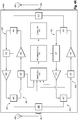
- FIG. 4A illustrates another example signal booster 400A with a multiplex detector, arranged in accordance with at least some embodiments described in this disclosure.
- the signal booster 400A may be part of a wireless communication system, such as the wireless communication system 100 illustrated in FIG. 1 .
- the signal booster 400A may include a first interface port 403 and a second interface port 407.
- the first interface port 403 may be coupled to a first antenna 404.
- the first antenna 404 may be configured to receive downlink signals from a wireless communication access point and to transmit uplink signals to the wireless communication access point.
- the second interface port 407 may be coupled to a second antenna 408.
- the second antenna 408 may be configured to receive uplink signals from a wireless device and to transmit downlink signal to the wireless device.
- the signal booster 400 may also include a first duplexer 402 coupled to the first interface port 403 and a second duplexer 406 coupled to the second interface port 407.
- the signal booster 400 may further include a first-band booster 410 and a second-band booster 440 coupled between the first and second duplexers 402 and 406.
- the first-band booster 410 may include a first first-band duplexer 412 and a second first-band duplexer 414.
- the first-band booster 410 may further include a first-band downlink amplification path 420 and a first-band uplink amplification path 430, which each may be coupled between the first first-band duplexer 412 and the second first-band duplexer 414.
- the first-band downlink amplification path 420 may include a first tap circuit 422 and a first amplification circuit 424.
- the first-band uplink amplification path 430 may include a second tap circuit 432 and a second amplification circuit 434.
- Each of the first and second tap circuits 422 and 432 may be coupled to the switch circuit 470.
- the first tap circuit 422 may be configured to provide a portion of the first-band downlink signal to the switch circuit 470.
- the second tap circuit 432 may be configured to provide a portion of the first-band uplink signal to the switch circuit 470.
- the second-band booster 440 may include a first second-band duplexer 442 and a second second-band duplexer 444.
- the second-band booster 440 may further include a second-band downlink amplification path 450 and a second-band uplink amplification path 460, which both may be coupled between the first second-band duplexer 442 and the second second-band duplexer 444.
- the second-band downlink amplification path 450 may include a third tap circuit 452 and a third amplification circuit 454.
- the second-band uplink amplification path 460 may include a fourth tap circuit 462 and a fourth amplification circuit 464.
- Each of the third and fourth tap circuits 452 and 462 may be coupled to the switch circuit 470.
- the third tap circuit 452 may be configured to provide a portion of the second-band downlink signal to the switch circuit 470.
- the fourth tap circuit 462 may be configured to provide a portion of the second-band uplink signal to the switch circuit 470.
- the switch circuit 470 may be coupled to the first tap circuit 422, the second tap circuit 432, the third tap circuit 452, the fourth tap circuit 462, and the RF detector circuit 472.
- the switch circuit 470 may be configured to switch between electrically coupling the first tap circuit 422, the second tap circuit 432, the third tap circuit 452, and the fourth tap circuit 462 to the RF detector circuit 472.
- the switch circuit 470 may be configured to provide a portion of a first-band downlink signal, a first-band uplink signal, a second-band downlink signal, and a second-band uplink signal, one at a time, to the RF detector circuit 472.
- the switch circuit 470 may electrically couple the first tap circuit 422, the second tap circuit 432, the third tap circuit 452, and the fourth tap circuit 462 to the RF detector circuit 472 for equal alternating periods. Alternately or additionally, the switch circuit 470 may couple the first tap circuit 422, the second tap circuit 432, the third tap circuit 452, and the fourth tap circuit 462 to the RF detector circuit 472 for unequal alternating periods, random periods, or following some other sequence.
- the switch circuit 472 may continue to receive a portion of the first-band and second-band uplink and downlink signals from the first tap circuit 422, the second tap circuit 432, the third tap circuit 452, and the fourth tap circuit 462 even when the first tap circuit 422, the second tap circuit 432, the third tap circuit 452, and the fourth tap circuit 462 are not electrically coupled to the RF detector circuit 472.
- the switch circuit 470 may be controlled by the control unit 474. In these and other embodiments, the switch circuit 470 may couple the RF detector circuit 472 to one of the first tap circuit 422, the second tap circuit 432, the third tap circuit 452, and the fourth tap circuit 462 based on a command from the control unit 474.
- the RF detector circuit 472 may be coupled to the control unit 474 and the switch circuit 470 and configured to receive a portion of downlink and uplink signals of the first and second bands at different times. In these and other embodiments, the RF detector circuit 472 may be configured to detect a power level of the portions of the downlink and uplink signals of the first and second bands. The RF detector circuit 472 may provide the detected power levels to the control unit 474. In some embodiments, the RF detector circuit 472 may include a diode, a log detector, or some other radio frequency detection circuit components.
- the control unit 474 may be configured to receive the detected power levels of the downlink and uplink signals of the first and second bands in the signal booster 400A. Based on the detected power levels of the downlink signals, the control unit 474 may adjust an amplification applied to the downlink and uplink signals of the first and second bands by the signal booster 400A.
- the signal booster 400A may include additional interface ports that are coupled to antennas that are configured to communicate with wireless devices.
- the signal booster 200 may include multiple other band boosters.
- the downlink and uplink amplifications paths 420, 430, 450, and 460 may include a different number or order of the amplification circuits than disclosed and illustrated.
- the first-band booster 410 and the second-band booster 440 may include filter circuits.
- the first tap circuit 422, the second tap circuit 432, the third tap circuit 452, and the fourth tap circuit 462 may be positioned in different locations within the first-band booster 410 and the second-band booster 440.
- the signal booster 400A may include additional switches configured in a manner analogous to the first and second switch circuits 330 and 332 of FIG. 3 .
- FIG. 4B illustrates another example signal booster 400B with a multiplex detector, arranged in accordance with at least some embodiments described in this disclosure.
- the signal booster 400B may be part of a wireless communication system, such as the wireless communication system 100 illustrated in FIG. 1 .
- the signal booster 400B may be analogous to the signal booster 400A, expect that the signal booster 400B may include first and second switch circuits 480 and 482 in place of the switch circuit 470 of signal booster 400A and may include first and second RF detector circuits 484 and 486 in place of the RF detector circuit 472 of signal booster 400A.
- the first switch circuit 480 may be coupled to the second tap circuit 432, the fourth tap circuit 462, and the first RF detector circuit 484.
- the first switch circuit 480 may be configured to switch between electrically coupling the second tap circuit 432 and the fourth tap circuit 462 to the first RF detector circuit 484.
- the first switch circuit 480 may provide a portion of the first-band uplink signal and the second-band uplink signal, one at a time, to the first RF detector circuit 484.
- the first switch circuit 480 may electrically couple the second tap circuit 432 and the fourth tap circuit 462 to the first RF detector circuit 484 for equal alternating periods. Alternately or additionally, the first switch circuit 480 may electrically couple the second tap circuit 432 and the fourth tap circuit 462 to the first RF detector circuit 484 for unequal alternating periods, random periods, or following some other sequence.
- the first RF detector circuit 484 may be coupled to the control unit 490 and the first switch circuit 480 and may be configured to receive a portion of uplink signals of the first and second bands at different times. In these and other embodiments, the first RF detector circuit 484 may be configured to detect a power level of the portions of the uplink signals of the first and second bands. The first RF detector circuit 484 may provide the detected power levels to the control unit 490. In some embodiments, the first RF detector circuit 484 may include a diode, a log detector, or some other radio frequency detection circuit components.
- the control unit 490 may be configured to receive the detected power levels of the uplink signals of the first and second bands in the signal booster 400B. Based on the detected power levels of the uplink signal of the first band, the control unit 490 may adjust an amplification applied to the uplink signals of the first band. Based on the detected power levels of the uplink signal of the second band, the control unit 490 may adjust an amplification applied to the uplink signals of the second band.
- the second switch circuit 482 may electrically couple the first tap circuit 422 and the third tap circuit 452 to the second RF detector circuit 486 for equal alternating periods. Alternately or additionally, the second switch circuit 482 may electrically couple the first tap circuit 422 and the third tap circuit 452 to the second RF detector circuit 486 for unequal alternating periods, random periods, or following some other sequence. In some embodiments, the first and second switch circuits 480 and 482 may switch at a similar or different rates, sequences, or periods.
- the second RF detector circuit 486 may be coupled to the control unit 490 and the second switch circuit 482 and may be configured to receive a portion of downlink signals of the first and second bands at different times. In these and other embodiments, the second RF detector circuit 486 may be configured to detect a power level of the portions of the downlink signals of the first and second bands. The second RF detector circuit 486 may provide the detected power levels to the control unit 490. In some embodiments, the second RF detector circuit 486 may include a diode, a log detector, or some other radio frequency detection circuit components.
- the control unit 490 may be configured to receive the detected power levels of the downlink signals of the first and second bands in the signal booster 400B. Based on the detected power levels of the downlink signal of the first band, the control unit 490 may adjust an amplification applied to the downlink signals of the first band. Based on the detected power levels of the downlink signal of the second band, the control unit 490 may adjust an amplification applied to the downlink signals of the second band.
- the first switch circuit 480 handling switching between the uplink signals and the second switch circuit 482 handling switching between the downlink signals may provide further isolation between the uplink and downlink amplification paths of the first-band booster 410 and the second-band booster 440 as compared to the single switch circuit 470 in the signal booster 400A in FIG. 4A .
- the signal booster 400B may multiple other band boosters.
- the downlink paths of the other band boosters may be coupled to the second switch circuit 482 and the uplink paths of the other band boosters may be coupled to the first switch circuit 480.
- the signal booster 400B may include additional switches configured in a manner analogous to the first and second switch circuits 330 and 332 of FIG. 3 .
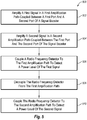
- FIG. 5 is a flowchart of an example method 500 of detecting signals in a signal booster, arranged in accordance with at least some embodiments described herein.
- the method 500 may be implemented, in some embodiments, by a signal booster, such as the signal booster 102, 200, 300, 400A or 400B of FIGS. 1 , 2 , 3 , 4A , and 4B , respectively.
- a signal booster such as the signal booster 102, 200, 300, 400A or 400B of FIGS. 1 , 2 , 3 , 4A , and 4B , respectively.
- the method 500 may begin at block 502, where a first signal in a first amplification path coupled between a first port and a second port of a signal booster may be amplified.
- a second signal in a second amplification path coupled between the first port and the second port of the signal booster may be amplified.
- the first signal may be a first-direction signal and the first amplification path may be a first-direction amplification path.
- the second signal may be a second-direction signal and the second amplification path may be a second-direction amplification path.
- a first-direction signal may be an uplink signal and a second-direction signal may be a downlink signal.
- a first-direction signal may be a downlink signal and a second-direction signal may be an uplink signal.
- the first signal may be a first first-direction signal and the first amplification path may be a first first-direction amplification path.
- the second signal may be a second first-direction signal and the second amplification path may be a second first-direction amplification path.
- a radio frequency detector may be coupled to the first amplification path to detect a power level of the first signal.
- the radio frequency detector may be decoupled from the first amplification path.
- the radio frequency detector may be coupled to the second amplification path to detect a power level of the second signal.
- decoupling the radio frequency detector from the first amplification path and coupling the radio frequency detector to the second amplification path may occur while the first signal is amplified by the first amplification path.
- the method 500 may further include controlling the amplification of the first signal in the first amplification path based on the power level of the first signal.
- the method 500 may further include controlling the amplification of the second signal in the second amplification path based on the power level of the second signal.
- the phrase “A or B” should be understood to include the possibilities of "A” or “B” or “A and B.”
Landscapes
- Engineering & Computer Science (AREA)
- Power Engineering (AREA)
- Computer Networks & Wireless Communication (AREA)
- Signal Processing (AREA)
- Transceivers (AREA)
- Mobile Radio Communication Systems (AREA)
Claims (11)
- Ein Signalverstärker, bestehend aus:einen ersten Anschluss (403):einen zweiten Anschluss (407);einen ersten Uplink-Verstärkungspfad (460), der eine erste Uplink-Abzweigschaltung (462) enthält, wobei der erste Uplink-Verstärkungspfad, der zwischen dem ersten Anschluss und dem zweiten Anschluss gekoppelt und so konfiguriert ist, dass er ein erstes Uplink-Signal einer ersten Frequenz in einem drahtlosen Kommunikationsnetzwerk durchlässt;einen zweiten Uplink-Verstärkungspfad (430), der eine zweite Uplink-Abzweigschaltung (432) enthält, wobei der zweite Uplink-Verstärkungspfad zwischen dem ersten Anschluss und dem zweiten Anschluss gekoppelt und so konfiguriert ist, dass er ein zweites Uplink-Signal einer zweiten Frequenz in dem drahtlosen Kommunikationsnetzwerk durchlässt;eine Uplink-Radiofrequenzdetektorschaltung (472);eine Uplink-Schaltschaltung (470),die mit der ersten Uplink-Abzweigschaltung, der zweiten Uplink-Abzweigschaltung und der Uplink-Radiofrequenzdetektorschaltung gekoppelt ist, wobei die Uplink-Schaltschaltung so konfiguriert ist, dass sie zwischen der Kopplung der Uplink-Radiofrequenzdetektorschaltung mit der ersten Uplink-Abzweigschaltung und der Kopplung der Uplink-Radiofrequenzdetektorschaltung mit der zweiten Uplink-Abzweigschaltung umschaltet, um entweder einen Teil des ersten Uplink-Signals oder einen Teil des zweiten Uplink-Signals an die Uplink-Radiofrequenzdetektorschaltung zu liefern;einen ersten Downlink-Verstärkungspfad (450),der eine erste Downlink-Abzweigschaltung (452) enthält, wobei der erste Downlink-Verstärkungspfad zwischen dem ersten Anschluss und dem zweiten Anschluss gekoppelt und so konfiguriert ist, dass er ein erstes Downlink-Signal einer dritten Frequenz in dem drahtlosen Kommunikationsnetzwerk durchlässt;einen zweiten Downlink-Verstärkungspfad (420),der eine zweite Downlink-Abzweigschaltung (422) enthält, wobei der zweite Downlink-Verstärkungspfad zwischen dem ersten Anschluss und dem zweiten Anschluss gekoppelt und so konfiguriert ist, dass er ein zweites Downlink-Signal einer vierten Frequenz in dem drahtlosen Kommunikationsnetzwerk durchlässt;eine Downlink-Radiofrequenzdetektorschaltung (472); undeine Downlink-Schaltschaltung (470),die mit der ersten Downlink-Abzweigschaltung, der zweiten Downlink-Abzweigschaltung und der Downlink-Radiofrequenzdetektorschaltung gekoppelt ist, wobei die Downlink-Schaltschaltung so konfiguriert ist, dass sie zwischen dem Koppeln der Downlink-Radiofrequenzdetektorschaltung mit der ersten Downlink-Abzweigschaltung und dem Koppeln der Downlink-Radiofrequenzdetektorschaltung mit der zweiten Downlink-Abzweigschaltung umschaltet, um entweder einen Teil des ersten Downlink-Signals oder einen Teil des zweiten Downlink-Signals an die Downlink-Radiofrequenzdetektorschaltung zu liefern.
- Signalverstärker nach Anspruch 1, wobei:jede der ersten Uplink-Abzweigschaltung, der zweiten Uplink-Abzweigschaltung, der ersten Downlink-Abzweigschaltung und der zweiten Downlink-Abzweigschaltung einen oder mehrere von einem Widerstand, einem Splitter, einem Kondensator und einem Richtungskoppler enthält; oderdie Uplink-Radiofrequenzdetektorschaltung und die Downlink-Radiofrequenzdetektorschaltung jeweils eine oder mehrere Dioden und einen Log-Detektor enthalten.
- Signalverstärker nach Anspruch 1, der ferner eine Steuereinheit (474) umfasst, die mit der Uplink-Schaltschaltung, dem Downlink-Schaltschaltung, dem Uplink-Radiofrequenzdetektorschaltung und dem Downlink-Radiofrequenzdetektorschaltung gekoppelt ist, wobei die Steuereinheit konfiguriert ist, um den Uplink-Schaltschaltung und den Downlink-Schaltschaltung zu steuern, um einen Uplink-Ausgang von der Uplink-Radiofrequenzdetektorschaltung zu empfangen und um einen Downlink-Ausgang von der Downlink-Radiofrequenzdetektorschaltung zu empfangen.
- Signalverstärker nach Anspruch 3, wobei die Steuereinheit so konfiguriert ist,
dass:sie eine erste Uplink-Verstärkung, die auf das erste Uplink-Signal in dem ersten Uplink-Verstärkungspfad angewendet wird, und eine zweite Uplink-Verstärkung, die auf das zweite Uplink-Signal in dem zweiten Uplink-Verstärkungspfad angewendet wird, basierend auf dem Uplink-Ausgang von der Uplink-Radiofrequenzdetektorschaltung einstellt, undeine erste Downlink-Verstärkung, die auf das erste Downlink-Signal in dem ersten Downlink-Verstärkungspfad angewendet wird, und eine zweite Downlink-Verstärkung, die auf das zweite Downlink-Signal in dem zweiten Downlink-Verstärkungspfad angewendet wird, basierend auf dem Downlink-Ausgang von der Downlink-Radiofrequenzdetektorschaltung einstellt. - Signalverstärker von Anspruch 1, wobei:das erste Uplink-Signal und das erste Downlink-Signal Teil desselben Kommunikationsfrequenzbandes im drahtlosen Kommunikationsnetz sind; oderdas zweite Uplink-Signal und das zweite Downlink-Signal Teil desselben Kommunikationsfrequenzbandes im drahtlosen Kommunikationsnetz sind.
- Verfahren, bestehend aus:Verstärken eines ersten Signals in erster Richtung in einem ersten Verstärkungspfad (460) in erster Richtung, der zwischen einem ersten Anschluss (403) und einem zweiten Anschluss (407) eines Signalverstärkers gekoppelt ist;Verstärken eines zweiten Signals in erster Richtung in einem zweiten Verstärkungspfad (430) in erster Richtung, der zwischen dem ersten Anschluss und dem zweiten Anschluss des Signalverstärkers gekoppelt ist;Koppeln eines Radiofrequenzdetektors (472) in erster Richtung mit dem ersten Verstärkungspfad in erster Richtung, um einen Leistungspegel des Signals in erster Richtung zu erfassen;Entkoppeln des Radiofrequenzdetektors in erster Richtung von dem Verstärkungspfad in erster Richtung;Koppeln des Radiofrequenzdetektors in erster Richtung mit dem zweiten Verstärkungspfad in erster Richtung, um einen Leistungspegel des Signals in erster Richtung zu erfassen;Verstärken eines ersten Signals in zweiter Richtung in einem ersten Verstärkungspfad in zweiter Richtung, der zwischen einem dritten Anschluss und einem vierten Anschluss des Signalverstärkers gekoppelt ist;Verstärken eines zweiten Signals in zweiter Richtung in einem zweiten Verstärkungspfad in zweiter Richtung, der zwischen dem dritten Anschluss und dem vierten Anschluss des Signalverstärkers gekoppelt ist;Koppeln eines Radiofrequenzdetektors in zweiter Richtung mit dem ersten Verstärkungspfad in zweiter Richtung, um einen Leistungspegel des ersten Signals in zweiter Richtung zu erfassen;Entkoppeln des Radiofrequenzdetektors in zweiter Richtung von dem ersten Verstärkungspfad in zweiter Richtung; undKoppeln des Radiofrequenzdetektors in zweiter Richtung mit dem zweiten Verstärkungspfad in zweiter Richtung, um einen Leistungspegel des zweiten Signals in zweiter Richtung zu erfassen.
- Verfahren nach Anspruch 6, wobei:
die Entkopplung des Radiofrequenz-detektors in erster Richtung von dem ersten Verstärkungspfad in erster Richtung und die Kopplung des Radiofrequenzdetektors in erster Richtung mit dem zweiten Verstärkungspfad in erster Richtung erfolgt, während das Signal in erster Richtung durch den ersten Verstärkungspfad in erster Richtung verstärkt wird. - Verfahren nach Anspruch 6, ferner umfassend:Steuern der Verstärkung des ersten Signals in erster Richtung in dem ersten Verstärkungspfad in erster Richtung auf der Grundlage des Leistungspegels des Signals in erster Richtung ; undSteuern der Verstärkung des zweiten Signals in erster Richtung in dem zweiten Verstärkungspfad in erster Richtung auf der Grundlage des Leistungspegels des Signals in erster Richtung.
- Verfahren nach Anspruch 6, wobei:der erste Verstärkungspfad in erster Richtung eine erste Abzweigschaltung (462) in erster Richtung enthält;der zweite Verstärkungspfad in erster Richtung eine zweite Abzweigschaltung (432) in erster Richtung enthält;der erste Verstärkungspfad in zweiter Richtung eine erste Abzweigschaltung (452) in zweiter Richtung enthält, undder zweite Verstärkungspfad in zweiter Richtung eine zweite Abzweigschaltung (422) in zweiter Richtung enthält,wobei jede der ersten Abzweigschaltung in erster Richtung, der zweiten Abzweigschaltung in erster Richtung, der ersten Abzweigschaltung in zweiter Richtung und der zweiten Abzweigschaltung in zweiter Richtung einen oder mehrere von einem Widerstand, einem Splitter, einem Kondensator und einem Richtungskoppler enthält.
- Verfahren nach Anspruch 6, wobei die Radiofrequenzdetektorschaltung in erster Richtung und die Radiofrequenzdetektorschaltung in zweiter Richtung jeweils eine oder mehrere Dioden und einen Log-Detektor enthalten.
- Verfahren nach Anspruch 9, ferner umfassend das Koppeln einer Steuerschaltung (474) mit der ersten Schaltschaltung in erster Richtung, der ersten Schaltschaltung in zweiter Richtung, der Radiofrequenzdetektorschaltung in erster Richtung und der Radiofrequenzdetektorschaltung in zweiter Richtung, wobei die Steuereinheit so konfiguriert ist, dass sie den ersten Schaltschaltung in erster Richtung und den ersten Schaltschaltung in zweiter Richtung steuert, zum Empfangen eines Ausgangs in erster Richtung von der Radiofrequenzdetektorschaltung in erster Richtung und zum Empfangen eines Ausgangs in zweiter Richtung von der Radiofrequenzdetektorschaltung in zweiter Richtung.
Applications Claiming Priority (2)
| Application Number | Priority Date | Filing Date | Title |
|---|---|---|---|
| US14/683,960 US9537455B2 (en) | 2015-04-10 | 2015-04-10 | Multiplex detector signal boosters |
| PCT/US2016/026762 WO2016164805A1 (en) | 2015-04-10 | 2016-04-08 | Multiplex detector signal boosters |
Publications (3)
| Publication Number | Publication Date |
|---|---|
| EP3281306A1 EP3281306A1 (de) | 2018-02-14 |
| EP3281306A4 EP3281306A4 (de) | 2019-01-02 |
| EP3281306B1 true EP3281306B1 (de) | 2020-08-05 |
Family
ID=57072378
Family Applications (1)
| Application Number | Title | Priority Date | Filing Date |
|---|---|---|---|
| EP16777416.5A Active EP3281306B1 (de) | 2015-04-10 | 2016-04-08 | Multiplex-detektorsignalverstärker |
Country Status (5)
| Country | Link |
|---|---|
| US (1) | US9537455B2 (de) |
| EP (1) | EP3281306B1 (de) |
| CN (1) | CN107438954B (de) |
| CA (1) | CA2979257C (de) |
| WO (1) | WO2016164805A1 (de) |
Families Citing this family (6)
| Publication number | Priority date | Publication date | Assignee | Title |
|---|---|---|---|---|
| JP2017118338A (ja) | 2015-12-24 | 2017-06-29 | 株式会社村田製作所 | 電力増幅モジュール |
| US10291269B2 (en) | 2015-12-24 | 2019-05-14 | Murata Manufacturing Co., Ltd. | Power amplification module |
| US10009049B2 (en) * | 2016-08-08 | 2018-06-26 | Kathrein-Werke Kg | Method for detecting and handling oscillations in a signal booster device, a signal booster device and a means of transportation comprising a signal booster device |
| CA3034697A1 (en) | 2016-09-02 | 2018-03-08 | Cellphone-Mate, Inc. | Radio frequency signal booster |
| CN116054967B (zh) * | 2023-03-31 | 2023-11-10 | 荣耀终端有限公司 | 一种功率检测电路及方法 |
| KR102790880B1 (ko) * | 2024-03-27 | 2025-04-04 | 주식회사 다온텍 | 5g 이동통신에서 스위칭 방식을 이용한 rf 전력 검출 장치 |
Family Cites Families (29)
| Publication number | Priority date | Publication date | Assignee | Title |
|---|---|---|---|---|
| US5245347A (en) | 1980-12-29 | 1993-09-14 | Raytheon Company | All weather tactical strike system (AWTSS) and method of operation |
| US5377255A (en) | 1992-07-14 | 1994-12-27 | Pcs Microcell International Inc. | RF repeaters for time division duplex cordless telephone systems |
| US5689801A (en) | 1994-11-14 | 1997-11-18 | Ericsson Inc. | Power monitoring system for a single site, split location trunked radio communication system |
| US5835848A (en) | 1996-12-30 | 1998-11-10 | Lucent Technologies Inc. | Range repeater for a transmission system |
| US6032020A (en) | 1997-07-28 | 2000-02-29 | Motorola, Inc. | Multi-repeater communication system |
| CA2323881A1 (en) * | 2000-10-18 | 2002-04-18 | Dps Wireless Inc. | Adaptive personal repeater |
| US6868254B2 (en) | 2001-08-30 | 2005-03-15 | Qualcomm Incorporated | Repeater with diversity transmission |
| US20040176026A1 (en) * | 2002-06-21 | 2004-09-09 | Tantivy Communications, Inc. | Covert spatially separated antenna package for repeater |
| WO2004038958A1 (en) | 2002-10-24 | 2004-05-06 | Widefi, Inc. | Wireless local area network repeater with in-band control channel |
| US8078100B2 (en) | 2002-10-15 | 2011-12-13 | Qualcomm Incorporated | Physical layer repeater with discrete time filter for all-digital detection and delay generation |
| US7623826B2 (en) | 2004-07-22 | 2009-11-24 | Frank Pergal | Wireless repeater with arbitrary programmable selectivity |
| CN2847754Y (zh) * | 2005-04-26 | 2006-12-13 | 京信通信技术(广州)有限公司 | 用于移动通信双工塔顶放大器的高集成化通用双工器模块 |
| US7865159B2 (en) | 2006-01-27 | 2011-01-04 | Qualcomm Incorporated | Repeater rise-over-thermal (RoT) value calibration |
| US8005513B2 (en) | 2006-03-16 | 2011-08-23 | Cellynx, Inc. | Cell phone signal booster |
| KR100721335B1 (ko) | 2006-12-13 | 2007-05-25 | (주)이노스 | Tdd 시스템에 사용되는 동기추출회로 및 동기신호를추출하는 방법 |
| US7729656B2 (en) * | 2007-01-03 | 2010-06-01 | Wilson Electronics | Cellular network low noise amplifiers for use with multiple frequencies |
| KR100893010B1 (ko) * | 2007-05-21 | 2009-04-10 | 주식회사 케이티프리텔 | 감쇄 장치를 구비한 중계기의 가변 감쇄 방법 및 그 원격관리 시스템 |
| DE502009005919C5 (de) | 2008-10-27 | 2022-01-05 | Andrew Wireless Systems Gmbh | Repeater und Verfahren zum Betrieb eines solchen Repeaters |
| US8472868B2 (en) | 2009-05-06 | 2013-06-25 | Telefonaktiebolaget Lm Ericsson (Publ) | Method and apparatus for MIMO repeater chains in a wireless communication network |
| US8457021B2 (en) | 2009-10-14 | 2013-06-04 | Cellvine Ltd. | Repeater system |
| CN202197283U (zh) * | 2011-08-03 | 2012-04-18 | 京信通信系统(中国)有限公司 | 通信中继装置及其驻波比检测装置 |
| US8583034B2 (en) | 2011-08-23 | 2013-11-12 | Wilson Electronics, Llc | Verifying and mitigating oscillation in amplifiers |
| US20130210500A1 (en) | 2012-02-09 | 2013-08-15 | Tait Limited | Power boosters for radio terminals |
| US9119061B2 (en) * | 2012-03-20 | 2015-08-25 | Farrokh Mohamadi | Integrated wafer scale, high data rate, wireless repeater placed on fixed or mobile elevated platforms |
| US9048940B2 (en) | 2012-08-31 | 2015-06-02 | Clear Rf, Llc | Passive bypass for network extending |
| US8818263B1 (en) * | 2013-03-15 | 2014-08-26 | Wilson Electronics, Llc | Circuit isolation using a signal splitter/combiner |
| WO2015002670A1 (en) | 2013-07-03 | 2015-01-08 | Wireless Extenders, Inc. | Multi-amplifier booster for a wireless communication system |
| KR102009531B1 (ko) | 2013-07-18 | 2019-08-12 | 엘에스전선 주식회사 | 중계기에서의 궤환 신호 제거 방법 및 그 중계기 |
| CN108112092B (zh) * | 2014-09-28 | 2021-04-30 | 安科讯(福建)科技有限公司 | 一种lte无线网卡终端设备 |
-
2015
- 2015-04-10 US US14/683,960 patent/US9537455B2/en active Active
-
2016
- 2016-04-08 WO PCT/US2016/026762 patent/WO2016164805A1/en not_active Ceased
- 2016-04-08 CN CN201680020433.0A patent/CN107438954B/zh not_active Expired - Fee Related
- 2016-04-08 EP EP16777416.5A patent/EP3281306B1/de active Active
- 2016-04-08 CA CA2979257A patent/CA2979257C/en active Active
Non-Patent Citations (1)
| Title |
|---|
| None * |
Also Published As
| Publication number | Publication date |
|---|---|
| US9537455B2 (en) | 2017-01-03 |
| EP3281306A4 (de) | 2019-01-02 |
| CN107438954A (zh) | 2017-12-05 |
| CA2979257C (en) | 2022-04-19 |
| CA2979257A1 (en) | 2016-10-13 |
| CN107438954B (zh) | 2020-07-03 |
| WO2016164805A1 (en) | 2016-10-13 |
| EP3281306A1 (de) | 2018-02-14 |
| US20160301371A1 (en) | 2016-10-13 |
Similar Documents
| Publication | Publication Date | Title |
|---|---|---|
| US9444543B2 (en) | Multiple-port signal boosters | |
| US20230396225A1 (en) | Multiple-Port Signal Boosters | |
| EP3281306B1 (de) | Multiplex-detektorsignalverstärker | |
| US8818263B1 (en) | Circuit isolation using a signal splitter/combiner | |
| US8818292B1 (en) | Bi-directional amplifier with a common signal detector | |
| US8755399B1 (en) | Common-direction duplexer | |
| AU2015201926B2 (en) | Configuring Signal Boosters | |
| US20150029909A1 (en) | Bi-directional signal booster | |
| US8909132B2 (en) | Bi-directional amplifier with a common amplification path | |
| EP3523890A1 (de) | Mehrfachverstärker-repeater für ein drahtloskommunikationssystem | |
| US8803635B1 (en) | Filter isolation using a circulator | |
| EP3499745B1 (de) | An einem turm montierter verstärker | |
| US20190068154A1 (en) | Multiple-port signal boosters | |
| KR100581732B1 (ko) | Tdd방식의 휴대 인터넷 무선중계기의 피드백신호감소장치 | |
| KR100333729B1 (ko) | 트리플 모드형 무선주파수 가변이득증폭 중계장치 | |
| KR20020057186A (ko) | 이동통신 변파 중계기에서의 다이버시티 장치 | |
| KR20120074512A (ko) | 간섭제거기능을 갖는 무선중계장치 |
Legal Events
| Date | Code | Title | Description |
|---|---|---|---|
| STAA | Information on the status of an ep patent application or granted ep patent |
Free format text: STATUS: THE INTERNATIONAL PUBLICATION HAS BEEN MADE |
|
| PUAI | Public reference made under article 153(3) epc to a published international application that has entered the european phase |
Free format text: ORIGINAL CODE: 0009012 |
|
| STAA | Information on the status of an ep patent application or granted ep patent |
Free format text: STATUS: REQUEST FOR EXAMINATION WAS MADE |
|
| 17P | Request for examination filed |
Effective date: 20170912 |
|
| AK | Designated contracting states |
Kind code of ref document: A1 Designated state(s): AL AT BE BG CH CY CZ DE DK EE ES FI FR GB GR HR HU IE IS IT LI LT LU LV MC MK MT NL NO PL PT RO RS SE SI SK SM TR |
|
| AX | Request for extension of the european patent |
Extension state: BA ME |
|
| DAV | Request for validation of the european patent (deleted) | ||
| DAX | Request for extension of the european patent (deleted) | ||
| A4 | Supplementary search report drawn up and despatched |
Effective date: 20181130 |
|
| RIC1 | Information provided on ipc code assigned before grant |
Ipc: H03F 3/19 20060101ALI20181126BHEP Ipc: H04B 17/40 20150101ALI20181126BHEP Ipc: H04B 1/40 20150101ALI20181126BHEP Ipc: H03F 3/24 20060101ALI20181126BHEP Ipc: H04B 17/14 20150101ALI20181126BHEP Ipc: H04B 7/155 20060101AFI20181126BHEP Ipc: H03F 3/21 20060101ALI20181126BHEP |
|
| GRAP | Despatch of communication of intention to grant a patent |
Free format text: ORIGINAL CODE: EPIDOSNIGR1 |
|
| STAA | Information on the status of an ep patent application or granted ep patent |
Free format text: STATUS: GRANT OF PATENT IS INTENDED |
|
| INTG | Intention to grant announced |
Effective date: 20200221 |
|
| GRAS | Grant fee paid |
Free format text: ORIGINAL CODE: EPIDOSNIGR3 |
|
| GRAA | (expected) grant |
Free format text: ORIGINAL CODE: 0009210 |
|
| STAA | Information on the status of an ep patent application or granted ep patent |
Free format text: STATUS: THE PATENT HAS BEEN GRANTED |
|
| AK | Designated contracting states |
Kind code of ref document: B1 Designated state(s): AL AT BE BG CH CY CZ DE DK EE ES FI FR GB GR HR HU IE IS IT LI LT LU LV MC MK MT NL NO PL PT RO RS SE SI SK SM TR |
|
| REG | Reference to a national code |
Ref country code: GB Ref legal event code: FG4D |
|
| REG | Reference to a national code |
Ref country code: CH Ref legal event code: EP |
|
| REG | Reference to a national code |
Ref country code: AT Ref legal event code: REF Ref document number: 1300203 Country of ref document: AT Kind code of ref document: T Effective date: 20200815 |
|
| REG | Reference to a national code |
Ref country code: DE Ref legal event code: R096 Ref document number: 602016041445 Country of ref document: DE |
|
| REG | Reference to a national code |
Ref country code: IE Ref legal event code: FG4D |
|
| REG | Reference to a national code |
Ref country code: LT Ref legal event code: MG4D |
|
| REG | Reference to a national code |
Ref country code: NL Ref legal event code: MP Effective date: 20200805 |
|
| REG | Reference to a national code |
Ref country code: AT Ref legal event code: MK05 Ref document number: 1300203 Country of ref document: AT Kind code of ref document: T Effective date: 20200805 |
|
| PG25 | Lapsed in a contracting state [announced via postgrant information from national office to epo] |
Ref country code: PT Free format text: LAPSE BECAUSE OF FAILURE TO SUBMIT A TRANSLATION OF THE DESCRIPTION OR TO PAY THE FEE WITHIN THE PRESCRIBED TIME-LIMIT Effective date: 20201207 Ref country code: ES Free format text: LAPSE BECAUSE OF FAILURE TO SUBMIT A TRANSLATION OF THE DESCRIPTION OR TO PAY THE FEE WITHIN THE PRESCRIBED TIME-LIMIT Effective date: 20200805 Ref country code: LT Free format text: LAPSE BECAUSE OF FAILURE TO SUBMIT A TRANSLATION OF THE DESCRIPTION OR TO PAY THE FEE WITHIN THE PRESCRIBED TIME-LIMIT Effective date: 20200805 Ref country code: BG Free format text: LAPSE BECAUSE OF FAILURE TO SUBMIT A TRANSLATION OF THE DESCRIPTION OR TO PAY THE FEE WITHIN THE PRESCRIBED TIME-LIMIT Effective date: 20201105 Ref country code: AT Free format text: LAPSE BECAUSE OF FAILURE TO SUBMIT A TRANSLATION OF THE DESCRIPTION OR TO PAY THE FEE WITHIN THE PRESCRIBED TIME-LIMIT Effective date: 20200805 Ref country code: NO Free format text: LAPSE BECAUSE OF FAILURE TO SUBMIT A TRANSLATION OF THE DESCRIPTION OR TO PAY THE FEE WITHIN THE PRESCRIBED TIME-LIMIT Effective date: 20201105 Ref country code: HR Free format text: LAPSE BECAUSE OF FAILURE TO SUBMIT A TRANSLATION OF THE DESCRIPTION OR TO PAY THE FEE WITHIN THE PRESCRIBED TIME-LIMIT Effective date: 20200805 Ref country code: FI Free format text: LAPSE BECAUSE OF FAILURE TO SUBMIT A TRANSLATION OF THE DESCRIPTION OR TO PAY THE FEE WITHIN THE PRESCRIBED TIME-LIMIT Effective date: 20200805 Ref country code: GR Free format text: LAPSE BECAUSE OF FAILURE TO SUBMIT A TRANSLATION OF THE DESCRIPTION OR TO PAY THE FEE WITHIN THE PRESCRIBED TIME-LIMIT Effective date: 20201106 Ref country code: SE Free format text: LAPSE BECAUSE OF FAILURE TO SUBMIT A TRANSLATION OF THE DESCRIPTION OR TO PAY THE FEE WITHIN THE PRESCRIBED TIME-LIMIT Effective date: 20200805 |
|
| PG25 | Lapsed in a contracting state [announced via postgrant information from national office to epo] |
Ref country code: RS Free format text: LAPSE BECAUSE OF FAILURE TO SUBMIT A TRANSLATION OF THE DESCRIPTION OR TO PAY THE FEE WITHIN THE PRESCRIBED TIME-LIMIT Effective date: 20200805 Ref country code: LV Free format text: LAPSE BECAUSE OF FAILURE TO SUBMIT A TRANSLATION OF THE DESCRIPTION OR TO PAY THE FEE WITHIN THE PRESCRIBED TIME-LIMIT Effective date: 20200805 Ref country code: NL Free format text: LAPSE BECAUSE OF FAILURE TO SUBMIT A TRANSLATION OF THE DESCRIPTION OR TO PAY THE FEE WITHIN THE PRESCRIBED TIME-LIMIT Effective date: 20200805 Ref country code: PL Free format text: LAPSE BECAUSE OF FAILURE TO SUBMIT A TRANSLATION OF THE DESCRIPTION OR TO PAY THE FEE WITHIN THE PRESCRIBED TIME-LIMIT Effective date: 20200805 Ref country code: IS Free format text: LAPSE BECAUSE OF FAILURE TO SUBMIT A TRANSLATION OF THE DESCRIPTION OR TO PAY THE FEE WITHIN THE PRESCRIBED TIME-LIMIT Effective date: 20201205 |
|
| PG25 | Lapsed in a contracting state [announced via postgrant information from national office to epo] |
Ref country code: RO Free format text: LAPSE BECAUSE OF FAILURE TO SUBMIT A TRANSLATION OF THE DESCRIPTION OR TO PAY THE FEE WITHIN THE PRESCRIBED TIME-LIMIT Effective date: 20200805 Ref country code: DK Free format text: LAPSE BECAUSE OF FAILURE TO SUBMIT A TRANSLATION OF THE DESCRIPTION OR TO PAY THE FEE WITHIN THE PRESCRIBED TIME-LIMIT Effective date: 20200805 Ref country code: CZ Free format text: LAPSE BECAUSE OF FAILURE TO SUBMIT A TRANSLATION OF THE DESCRIPTION OR TO PAY THE FEE WITHIN THE PRESCRIBED TIME-LIMIT Effective date: 20200805 Ref country code: EE Free format text: LAPSE BECAUSE OF FAILURE TO SUBMIT A TRANSLATION OF THE DESCRIPTION OR TO PAY THE FEE WITHIN THE PRESCRIBED TIME-LIMIT Effective date: 20200805 Ref country code: SM Free format text: LAPSE BECAUSE OF FAILURE TO SUBMIT A TRANSLATION OF THE DESCRIPTION OR TO PAY THE FEE WITHIN THE PRESCRIBED TIME-LIMIT Effective date: 20200805 |
|
| REG | Reference to a national code |
Ref country code: DE Ref legal event code: R097 Ref document number: 602016041445 Country of ref document: DE |
|
| PG25 | Lapsed in a contracting state [announced via postgrant information from national office to epo] |
Ref country code: AL Free format text: LAPSE BECAUSE OF FAILURE TO SUBMIT A TRANSLATION OF THE DESCRIPTION OR TO PAY THE FEE WITHIN THE PRESCRIBED TIME-LIMIT Effective date: 20200805 |
|
| PLBE | No opposition filed within time limit |
Free format text: ORIGINAL CODE: 0009261 |
|
| STAA | Information on the status of an ep patent application or granted ep patent |
Free format text: STATUS: NO OPPOSITION FILED WITHIN TIME LIMIT |
|
| PG25 | Lapsed in a contracting state [announced via postgrant information from national office to epo] |
Ref country code: SK Free format text: LAPSE BECAUSE OF FAILURE TO SUBMIT A TRANSLATION OF THE DESCRIPTION OR TO PAY THE FEE WITHIN THE PRESCRIBED TIME-LIMIT Effective date: 20200805 |
|
| 26N | No opposition filed |
Effective date: 20210507 |
|
| PG25 | Lapsed in a contracting state [announced via postgrant information from national office to epo] |
Ref country code: IT Free format text: LAPSE BECAUSE OF FAILURE TO SUBMIT A TRANSLATION OF THE DESCRIPTION OR TO PAY THE FEE WITHIN THE PRESCRIBED TIME-LIMIT Effective date: 20200805 |
|
| PG25 | Lapsed in a contracting state [announced via postgrant information from national office to epo] |
Ref country code: SI Free format text: LAPSE BECAUSE OF FAILURE TO SUBMIT A TRANSLATION OF THE DESCRIPTION OR TO PAY THE FEE WITHIN THE PRESCRIBED TIME-LIMIT Effective date: 20200805 |
|
| PG25 | Lapsed in a contracting state [announced via postgrant information from national office to epo] |
Ref country code: MC Free format text: LAPSE BECAUSE OF FAILURE TO SUBMIT A TRANSLATION OF THE DESCRIPTION OR TO PAY THE FEE WITHIN THE PRESCRIBED TIME-LIMIT Effective date: 20200805 |
|
| PG25 | Lapsed in a contracting state [announced via postgrant information from national office to epo] |
Ref country code: LU Free format text: LAPSE BECAUSE OF NON-PAYMENT OF DUE FEES Effective date: 20210408 |
|
| REG | Reference to a national code |
Ref country code: BE Ref legal event code: MM Effective date: 20210430 |
|
| PG25 | Lapsed in a contracting state [announced via postgrant information from national office to epo] |
Ref country code: CH Free format text: LAPSE BECAUSE OF NON-PAYMENT OF DUE FEES Effective date: 20210430 Ref country code: LI Free format text: LAPSE BECAUSE OF NON-PAYMENT OF DUE FEES Effective date: 20210430 |
|
| PG25 | Lapsed in a contracting state [announced via postgrant information from national office to epo] |
Ref country code: IE Free format text: LAPSE BECAUSE OF NON-PAYMENT OF DUE FEES Effective date: 20210408 |
|
| PG25 | Lapsed in a contracting state [announced via postgrant information from national office to epo] |
Ref country code: IS Free format text: LAPSE BECAUSE OF FAILURE TO SUBMIT A TRANSLATION OF THE DESCRIPTION OR TO PAY THE FEE WITHIN THE PRESCRIBED TIME-LIMIT Effective date: 20201205 |
|
| PG25 | Lapsed in a contracting state [announced via postgrant information from national office to epo] |
Ref country code: BE Free format text: LAPSE BECAUSE OF NON-PAYMENT OF DUE FEES Effective date: 20210430 |
|
| PG25 | Lapsed in a contracting state [announced via postgrant information from national office to epo] |
Ref country code: HU Free format text: LAPSE BECAUSE OF FAILURE TO SUBMIT A TRANSLATION OF THE DESCRIPTION OR TO PAY THE FEE WITHIN THE PRESCRIBED TIME-LIMIT; INVALID AB INITIO Effective date: 20160408 |
|
| PG25 | Lapsed in a contracting state [announced via postgrant information from national office to epo] |
Ref country code: CY Free format text: LAPSE BECAUSE OF FAILURE TO SUBMIT A TRANSLATION OF THE DESCRIPTION OR TO PAY THE FEE WITHIN THE PRESCRIBED TIME-LIMIT Effective date: 20200805 |
|
| P01 | Opt-out of the competence of the unified patent court (upc) registered |
Effective date: 20230601 |
|
| REG | Reference to a national code |
Ref country code: DE Ref legal event code: R082 Ref document number: 602016041445 Country of ref document: DE Representative=s name: TER MEER STEINMEISTER & PARTNER PATENTANWAELTE, DE |
|
| PG25 | Lapsed in a contracting state [announced via postgrant information from national office to epo] |
Ref country code: MK Free format text: LAPSE BECAUSE OF FAILURE TO SUBMIT A TRANSLATION OF THE DESCRIPTION OR TO PAY THE FEE WITHIN THE PRESCRIBED TIME-LIMIT Effective date: 20200805 |
|
| PG25 | Lapsed in a contracting state [announced via postgrant information from national office to epo] |
Ref country code: TR Free format text: LAPSE BECAUSE OF FAILURE TO SUBMIT A TRANSLATION OF THE DESCRIPTION OR TO PAY THE FEE WITHIN THE PRESCRIBED TIME-LIMIT Effective date: 20200805 |
|
| PG25 | Lapsed in a contracting state [announced via postgrant information from national office to epo] |
Ref country code: MT Free format text: LAPSE BECAUSE OF FAILURE TO SUBMIT A TRANSLATION OF THE DESCRIPTION OR TO PAY THE FEE WITHIN THE PRESCRIBED TIME-LIMIT Effective date: 20200805 |
|
| PGFP | Annual fee paid to national office [announced via postgrant information from national office to epo] |
Ref country code: DE Payment date: 20250429 Year of fee payment: 10 |
|
| PGFP | Annual fee paid to national office [announced via postgrant information from national office to epo] |
Ref country code: GB Payment date: 20250428 Year of fee payment: 10 |
|
| PGFP | Annual fee paid to national office [announced via postgrant information from national office to epo] |
Ref country code: FR Payment date: 20250425 Year of fee payment: 10 |