EP3280935B1 - Drosselklappe mit verbessertem sitzring mit sofortigem klappenverschluss und gleichmässiger erhöhung der abdichtung - Google Patents
Drosselklappe mit verbessertem sitzring mit sofortigem klappenverschluss und gleichmässiger erhöhung der abdichtung Download PDFInfo
- Publication number
- EP3280935B1 EP3280935B1 EP15722754.7A EP15722754A EP3280935B1 EP 3280935 B1 EP3280935 B1 EP 3280935B1 EP 15722754 A EP15722754 A EP 15722754A EP 3280935 B1 EP3280935 B1 EP 3280935B1
- Authority
- EP
- European Patent Office
- Prior art keywords
- valve
- seat ring
- disc
- contact
- elliptic
- Prior art date
- Legal status (The legal status is an assumption and is not a legal conclusion. Google has not performed a legal analysis and makes no representation as to the accuracy of the status listed.)
- Active
Links
- 238000007789 sealing Methods 0.000 title claims description 59
- 230000000694 effects Effects 0.000 claims description 17
- 230000008961 swelling Effects 0.000 claims description 4
- 210000003739 neck Anatomy 0.000 description 17
- 239000012530 fluid Substances 0.000 description 14
- 239000000463 material Substances 0.000 description 13
- 230000003247 decreasing effect Effects 0.000 description 10
- 230000035515 penetration Effects 0.000 description 10
- 230000002093 peripheral effect Effects 0.000 description 9
- 230000002265 prevention Effects 0.000 description 9
- 230000006835 compression Effects 0.000 description 7
- 238000007906 compression Methods 0.000 description 7
- 238000013461 design Methods 0.000 description 7
- 238000007689 inspection Methods 0.000 description 6
- 230000032683 aging Effects 0.000 description 5
- 230000035882 stress Effects 0.000 description 5
- 230000007423 decrease Effects 0.000 description 3
- 238000013459 approach Methods 0.000 description 2
- 229910001039 duplex stainless steel Inorganic materials 0.000 description 2
- 239000008187 granular material Substances 0.000 description 2
- 230000003252 repetitive effect Effects 0.000 description 2
- 208000035859 Drug effect increased Diseases 0.000 description 1
- 229910001141 Ductile iron Inorganic materials 0.000 description 1
- 238000006073 displacement reaction Methods 0.000 description 1
- 230000007717 exclusion Effects 0.000 description 1
- 238000003780 insertion Methods 0.000 description 1
- 230000037431 insertion Effects 0.000 description 1
- 230000007774 longterm Effects 0.000 description 1
- 238000012986 modification Methods 0.000 description 1
- 230000004048 modification Effects 0.000 description 1
- 230000000704 physical effect Effects 0.000 description 1
- 230000002250 progressing effect Effects 0.000 description 1
- 239000012858 resilient material Substances 0.000 description 1
- 238000009751 slip forming Methods 0.000 description 1
- 229910001220 stainless steel Inorganic materials 0.000 description 1
- 239000010935 stainless steel Substances 0.000 description 1
- 238000012360 testing method Methods 0.000 description 1
- 238000012546 transfer Methods 0.000 description 1
- 238000004073 vulcanization Methods 0.000 description 1
Images


Classifications
-
- F—MECHANICAL ENGINEERING; LIGHTING; HEATING; WEAPONS; BLASTING
- F16—ENGINEERING ELEMENTS AND UNITS; GENERAL MEASURES FOR PRODUCING AND MAINTAINING EFFECTIVE FUNCTIONING OF MACHINES OR INSTALLATIONS; THERMAL INSULATION IN GENERAL
- F16K—VALVES; TAPS; COCKS; ACTUATING-FLOATS; DEVICES FOR VENTING OR AERATING
- F16K1/00—Lift valves or globe valves, i.e. cut-off apparatus with closure members having at least a component of their opening and closing motion perpendicular to the closing faces
- F16K1/16—Lift valves or globe valves, i.e. cut-off apparatus with closure members having at least a component of their opening and closing motion perpendicular to the closing faces with pivoted closure-members
- F16K1/18—Lift valves or globe valves, i.e. cut-off apparatus with closure members having at least a component of their opening and closing motion perpendicular to the closing faces with pivoted closure-members with pivoted discs or flaps
- F16K1/22—Lift valves or globe valves, i.e. cut-off apparatus with closure members having at least a component of their opening and closing motion perpendicular to the closing faces with pivoted closure-members with pivoted discs or flaps with axis of rotation crossing the valve member, e.g. butterfly valves
- F16K1/226—Shaping or arrangements of the sealing
- F16K1/2263—Shaping or arrangements of the sealing the sealing being arranged on the valve seat
-
- F—MECHANICAL ENGINEERING; LIGHTING; HEATING; WEAPONS; BLASTING
- F16—ENGINEERING ELEMENTS AND UNITS; GENERAL MEASURES FOR PRODUCING AND MAINTAINING EFFECTIVE FUNCTIONING OF MACHINES OR INSTALLATIONS; THERMAL INSULATION IN GENERAL
- F16K—VALVES; TAPS; COCKS; ACTUATING-FLOATS; DEVICES FOR VENTING OR AERATING
- F16K1/00—Lift valves or globe valves, i.e. cut-off apparatus with closure members having at least a component of their opening and closing motion perpendicular to the closing faces
- F16K1/16—Lift valves or globe valves, i.e. cut-off apparatus with closure members having at least a component of their opening and closing motion perpendicular to the closing faces with pivoted closure-members
- F16K1/18—Lift valves or globe valves, i.e. cut-off apparatus with closure members having at least a component of their opening and closing motion perpendicular to the closing faces with pivoted closure-members with pivoted discs or flaps
- F16K1/22—Lift valves or globe valves, i.e. cut-off apparatus with closure members having at least a component of their opening and closing motion perpendicular to the closing faces with pivoted closure-members with pivoted discs or flaps with axis of rotation crossing the valve member, e.g. butterfly valves
- F16K1/222—Shaping of the valve member
-
- F—MECHANICAL ENGINEERING; LIGHTING; HEATING; WEAPONS; BLASTING
- F16—ENGINEERING ELEMENTS AND UNITS; GENERAL MEASURES FOR PRODUCING AND MAINTAINING EFFECTIVE FUNCTIONING OF MACHINES OR INSTALLATIONS; THERMAL INSULATION IN GENERAL
- F16K—VALVES; TAPS; COCKS; ACTUATING-FLOATS; DEVICES FOR VENTING OR AERATING
- F16K1/00—Lift valves or globe valves, i.e. cut-off apparatus with closure members having at least a component of their opening and closing motion perpendicular to the closing faces
- F16K1/16—Lift valves or globe valves, i.e. cut-off apparatus with closure members having at least a component of their opening and closing motion perpendicular to the closing faces with pivoted closure-members
- F16K1/18—Lift valves or globe valves, i.e. cut-off apparatus with closure members having at least a component of their opening and closing motion perpendicular to the closing faces with pivoted closure-members with pivoted discs or flaps
- F16K1/22—Lift valves or globe valves, i.e. cut-off apparatus with closure members having at least a component of their opening and closing motion perpendicular to the closing faces with pivoted closure-members with pivoted discs or flaps with axis of rotation crossing the valve member, e.g. butterfly valves
- F16K1/226—Shaping or arrangements of the sealing
- F16K1/2263—Shaping or arrangements of the sealing the sealing being arranged on the valve seat
- F16K1/2265—Shaping or arrangements of the sealing the sealing being arranged on the valve seat with a channel- or U-shaped seal covering a central body portion
-
- F—MECHANICAL ENGINEERING; LIGHTING; HEATING; WEAPONS; BLASTING
- F16—ENGINEERING ELEMENTS AND UNITS; GENERAL MEASURES FOR PRODUCING AND MAINTAINING EFFECTIVE FUNCTIONING OF MACHINES OR INSTALLATIONS; THERMAL INSULATION IN GENERAL
- F16K—VALVES; TAPS; COCKS; ACTUATING-FLOATS; DEVICES FOR VENTING OR AERATING
- F16K27/00—Construction of housing; Use of materials therefor
- F16K27/02—Construction of housing; Use of materials therefor of lift valves
- F16K27/0209—Check valves or pivoted valves
- F16K27/0218—Butterfly valves
Definitions
- the present invention relates to a butterfly valve, more particularly to improvements in the sealing structure of a butterfly valve seat ring wherein a valve disc provided in a valve body is rotated about a valve axis in order to, open and close a valve, and control a fluid flow through the butterfly valve.
- a valve disc of a substantially disc-like shape provided in a valve body is rotated about a valve axis, which passes through in the diametric direction of the valve disc, in order to open and close a valve, and control a fluid flow through the butterfly valve.
- a seat ring made of a rubber elastic body.
- Document JP 3045671 B2 discloses a pair of valve stem insertion holes 11 drilled through an annular seat ring 10 attached to the internal surface of a hollow cylindrical body 30 of rigid material, and boss parts 12 formed around the holes 11, so as to keep a valve element in forced contact therewith at all times.
- a conical-head seat part is circumferentially and continuously formed between the pair of boss parts 12, so that the valve element, when closed, is forcibly kept in contact therewith.
- the conical-head seat part is formed out of the first conical-head seat part 13, and the second conical-head seat part 14 enlarged to the same shape (analogous shape), so that the bases 13a and 14a of respective parts 13 and 14 are in parallel with each other for substantiating the sealing function and mechanical strength.
- the disc Due to the geometry of the first conical-head seat part surface 13 especially in vicinity of the stems where the inclination of said surface is steep, the disc will create extreme tension in area surrounding the line 13a causing damage to the seat ring while repetitive closing of the valve.
- the sealing ability of the valve is rapidly decreasing, and thus overall efficiency of the valve.
- a butterfly valve of the type including a valve casing, a seat ring provided in the valve casing and a butterfly rotatably provided in the valve casing.
- the butterfly valve further includes a pair of semicircular sealing projections formed on the seat ring.
- the sealing projections are arranged and configured such that one sealing projection engages with one side of the valve disc while another sealing projection engages with another side of the valve disc.
- Object of the disclosed invention is to provide a butterfly valve wherein the circumference of the valve does not press into the inner surface of the seat ring when the valve is in the closed position.
- junction of the inclined contact surface 28 and top portion 27 in cross-section is projected as a vertical line which coincides with the plane passing through seat ring centerline.
- Document US5741006A discloses a butterfly valve that includes a valve member which provides improved sealing properties together with a seating ring.
- An inside projecting ridge 35 makes contact with the valve member 28 so as to block the fluid flow.
- the inside projecting ridge 35 includes vane-contact portions 41a and 41b and shaft supporting portion 33.
- the vane-contact portions 41a and 41b respectively come into pressure-contact with front and rear circumferential edges 39 and 40 of the vane 37 and 38 of the valve member 28.
- the shaft supporting portion 33 presses against the end surface of a shaft receptacle 50 of the valve member 28 in the radial direction of the valve member 28.
- portions of the circumferential edges 39 and 40 which come into pressure-contact with the pressure-contact sealing surfaces 43 and 44 of the seating ring 23 are formed flat.
- the vanes of the valve member 28 are located at point-symmetrical positions centered on the shaft receptacles and extended tangentially with respect to the front and back circumferential surfaces of the shaft receptacles.
- features of a seating ring 23 are designed in dependence on the features of the valve member 28, where the valve member 28 is roughly a disk-form element with a radius of R with vanes extending tangentially with respect to the front and back circumferential surfaces of the shaft receptacles.
- valve seat ring formed of resilient material within the flow passage to improve the sealing function. Notwithstanding the use of such seat rings, leakage problems, high torque actuators are still necessary to operate the valve, compression of the significant amount of seat ring material during complete closure of the disk resulting in enormous stresses in the seat ring, tearing off or rapidly growing old of seat rings particularly near the stem, losing physical properties resulting in decrease of sealing effectively are still present in many butterfly valves.
- An object of the present invention is to provide butterfly valve seat ring wherein a periphery of a valve disc, along the entire circumference of the valve disc, is entirely and substantially at the same instant brought into contact with a semi-elliptic first contact/closure curve of the seat ring resulting in instantaneous valve closing. Furthermore, an object of the present invention is to provide butterfly valve seat ring wherein the sealing projection is of variable cross section shape and contact surface is formed as tapered surface displaced by offset "h" from plane defined by vertical and transversal valve centerline (both perpendicular to the flow direction) in the valve closing direction, resulting in uniform seal along the entire circumference of the valve disc where the seal effect uniformly increases while rotating the disc in closing direction; up to fully closed position i.e. disc position where disc plate face is perpendicular to the fluid flow direction.
- the present invention provides a seat ring for a butterfly valve provided at an inner circumferential surface of a valve body so as to create a seal between the inner circumferential surface of a valve body and the valve disc when closing the valve.
- the sealing projection is continuously protruding inwardly and is provided between a pair of bosses formed around a pair of opposite valve stem holes for inserting valve stems positioned radially outwardly of a flow passage direction, and consists of contact surface and adjacent semi-elliptic surface, wherein the contact line of the contact surface and top portion of the adjacent semi-elliptic surface is displaced by offset "h" from plane defined by vertical and transversal valve centerline in disc closing direction, wherein offset "h" amounts at least half of the valve disc periphery thickness.
- the sealing projection is arranged and configured such that one sealing projection engages with one side of the valve disc while another sealing projection engages with another side of the valve disc.
- the contact surface curved swelling towards the periphery of the valve disc in disc opening direction is shaped as a straight line i.e. tapered surface formed with the slant varying in the circumferential direction in such a manner that the slant is steep in the vicinity of the stems, and gentle in the central portion away from the stems.
- valve seat design provides, at different fluid pressure, closing of the valve at different degrees i.e. minimal disc - seat ring deformation to oppose certain pressure. Therefore smaller actuator for closing the valve at lower pressure in the pipeline is required.
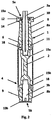
- a butterfly valve according to the present invention is disposed at a joint portion between two pipes through which a fluid flows, and adapted to open and close the flow passage and besides to control the fluid flow rate.
- the valve body 1 is made of, for example, ductile cast iron and comprises a tubular casing body 6 tightly sandwiched between two pipes in the flow passage direction, flange 7 to fit and connect the valve into pipeline, necks 8a and 8b to place in the shafts 3a and 3b, circular stem holes 9 being drilled to insert the stems 3a and 3b, connection plate 10 located on top of neck 8a to fit the actuator for operating the valve.
- Tubular casing body 6 comprises a circular protrusion 11 being formed continuously in the inner circumferential surface of the tubular casing body 6, and two circular grooves being formed continuously from stem hole 9 to other stem hole 9 in the inner circumferential surface of the circular protrusion 11 and a slippage prevention means 16, shown in figures 4 and 5 , of the seat ring 4 is fitted therein.
- a circular grove is formed around axis 3 in stem holes 9 in the inner circumferential surface of said protrusion 11 and a slippage prevention means 17 of the seat ring 4 is fitted therein.
- Said grooves and fitted slippage prevention means 16 and 17 are provided to prevent a deviation of the seat ring 4 in the flow passage direction and its rotation around axis 3 while opening and closing the disc 2.
- Valve necks 8a and 8b are provided at the valve body 1 radially outwardly in the direction of the valve axis 3 and respective stem holes 9 are drilled through, through stem holes 9 valve stems 3a and 3b are inserted.
- the connection plate 10 with holes for screws to fit the actuator for operating the valve is located on top of the body neck 8a.
- flange 7 to fit and connect the valve accurately between two pipes into pipeline comprises drilled holes through which threaded rods are inserted and valve is tighten into pipeline. With Lug valve type, thread is machined into flange so the bolts are inserted and used to tighten the valve accurately between two pipes into pipeline. Flange 7 is casted blind and drilled or machined afterwards, according to requested standard.
- Top prevention means 5a comprises two half-plates 12 put together into circumferential groove positioned near the upper end of the stem 3a, to restrain stem axial movement and enable its fallout from the neck 8a, inserted together into stem hole 9, covered by cover plate 13a to lock it in place, fastened with four screws 14 to the body neck 8a.
- Bottom prevention means 5b comprise only cover plate 13b, to restrain stem 3b axial movement and its falling out from neck 8b, fastened in place with four screws like those 14 used on the top but which cannot be seen in cross section shown in Fig.
- the valve disc 2 is of substantially a disc-like shape formed of, for example, stainless steel and has a diameter smaller than an inner diameter of the annular protrusion of the valve body 1.
- the valve disc 2 is disposed inside the valve body 1 by arranging its diametrical direction in conformity with the valve axis 3. By rotating said valve disc 2 about the valve axis 3, when its plate face is made parallel to the direction of fluid flow, the flow passage is opened, and when the plate face is made perpendicular to the direction of fluid flow, the valve is in fully closed position. By adjusting the rotation angle of the valve disc 2, the fluid flow rate is controlled subject to rotation angle.
- a fitting hole of the stem fitting portion 15a is substantially of square in a cross section while a fitting hole of the stem fitting portion 15b is substantially of circular cross section.
- the valve stem 3a is made of, for example, duplex stainless steel and is of bar-like shape having a circular cross section and inserted into the stem hole 9 of body neck 8a.
- the upper end of the valve stem 3a extending outwardly of the body neck 8a is formed substantially in a square shape in cross section for engagement with an operating handle or actuator not illustrated to rotate the valve stem 3a about the valve axis 3.
- the lower end of the valve stem 3a extending to the inside of the valve body 1 is formed substantially in a square shape in cross section for engagement with the fitting hole of the stem fitting portion 15a and the valve disc 2 can be rotated about the valve axis 3 when the valve stem 3a is rotated about the valve axis by handle or actuator.
- a circular cross sectional portion of the valve stem 3a positioned near the upper end of the body neck 8a is provided with a circumferential groove in which the inner periphery of two half plates 12, locked from above with fastened cover plate 13a, are fitted and the valve stem 3a is prevented from slipping out.
- the valve stem 3b is made of, for example, duplex stainless steel and is of bar-like shape having a circular cross section and inserted in the body neck 8b.
- valve stem 3b extends to the inside of the valve body 1 so as to be fitted in the circular fitting hole of the stem fitting portion 15b, thereby supporting the valve disc 2 rotatably about the valve axis 3.
- the axially outer end of the valve stem 3b is prevented from axially outward movement by the cover plate 13b fastened to the body neck 8b with screws.
- the connection between both valve stems 3a and 3b and body necks 8a and 8b is made through bearings which take and transfer the load from the valve stems to the body, and contribute to friction reduced stem rotation. In contact area between stems and bearings sealing is performed by o-rings inserted into stem grooves.
- valve stem 3a is supported by two bearings positioned on opposite sides of the stem, and valve stem 3b is supported by one bearing only.
- Number and size of bearings as well as number of o-rings per bearing vary with the valve size, pipeline nominal pressure, medium, etc.
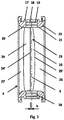
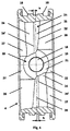
- Figurs 3 to 5 illustrate seat ring 4.
- the seat ring 4 is formed of rubber elastic body and has an outside face opened radially outwardly and is of a ring-like shape having two circular bosses 16 fitted into two matching grooves in body circular protrusion 11.
- a circular boss 17 is formed around axis 3 on the outer circumferential surface of seat ring 4 and fitted into a circular groove formed around axis 3 in stem holes 9 in the inner circumferential surface of said protrusion 11.
- the outer side of the seat ring 4 is bent inwardly to embrace the protrusion 11 and attached to the inner circumferential surface of the valve body 1.
- the outer diameter of the seat ring 4 is adjusted to the size of the valve and to fit in the valve body 1, and its inner diameter is larger than the diameter of the valve disc 2 in order to provide sealing.
- Said circular bosses 16 and 17 are slippage prevention means, and with outer sides of the seat ring 4 bent inwardly to embrace the protrusion 11, prevent deviation of the seat ring 4 in the flow passage direction and its rotation around axis 3 while opening and closing the valve disc 2.
- a pair of circularly shaped stem holes 18 made in seat ring through which the valve stems 3a and 3b are inserted.
- Two parallely arranged circular lips 19 located on the inner periphery of each stem hole 18 exactly follow the geometry of the hole thus achieving increased sealing with decreased torque necessary to operate the valve. This two lips 19 in contact with the stem create chambers that prevent outflow of medium from the pipeline through the stem opening.
- a pair of bosses 20 are formed protruding inwardly around the valve stem holes 18 to make a seal with the fitting portions 15 of the valve disc 2 positioned near to the vertical valve axis 3.
- Said boss 20 consist of a flat sliding surface 21 on which the flat radially outward portion of the stem fitting portions 15a i.e. 15b of the valve disc 2 slides and a curved/inclined surface 22 extending from the edge of said flat sliding surface 21 to the edge of the seat ring 4.
- the form of slide surface 21 is defined by several parameters, such as disc diameter, closing angle where the valve disc 2 touches the semi-elliptic first contact/closure curve 25' for the first time, sealing tightness between the valve disc and seat ring.
- sealing projection 23 continuously protruding inwardly in the circumferential direction.
- the sealing projection 23 is arranged and configured such that one sealing projection engages with one side of the valve disc 2 while another sealing projection engages with another side of the valve disc 2.
- sealing projection 23 constitutes curved swelling surfaces consisting of contact surface 25 and adjacent semi-elliptic surface 24.
- the semi-elliptic edge 24' of the adjacent semi-elliptic surface 24 is displaced by offset "h" from plane defined by vertical valve centerline 3 and transversal valve centerline 28 in valve closing direction.
- offset "h” is shift at top portion of the semi-elliptic edge 24' in valve closing direction from the transverse centerline 28, wherein offset “h” amounts at least half of the disc periphery thickness.
- the semi-elliptic edge 24' is closely contacting with periphery of the valve disc 2 along the entire circumference of the valve disc (2).
- the contact surface 25 has semi-elliptic first contact/closure curve 25' closely contacting with the valve disc 2 in very first closed position of the valve - when the disc touches the sealing projection 23 for the first time thus making not-strong but uniform sealing along the entire circumference of the valve disc. Between semi-elliptic first contact/closure curve 25' and right seat ring edge ( Fig. 3 and 4 ) sloping circular surface 26 is arranged.
- the semi-elliptic surface 24 is formed parallel to the flow passage and, due to the sealing functionality, its smallest inner diameter is smaller than that of the valve disc 2.
- semi-elliptic surface 24 provides larger cross section surface of the valve opening which means increased medium flow resulting in increased flow factor Kv, and decreased drag resulting in decreased pressure drop on the valve i.e. better coefficient Cd.
- Surface 27 is arranged in continuation of the semi-elliptic surface 24 to the left seat ring 4 edge ( Fig. 3 and 4 ).
- the contact surface 25 is formed as an inclined face (tapered face) slanting from the semi-elliptic edge 24' of the semi-elliptic surface 24 towards the semi-elliptic first contact/closure curve 25' of the seat ring 4, where the slant is varying in the circumferential direction in such a manner that the slant is steep in the vicinity of the bosses 20, and gentle in the central portion between the bosses 20.
- the semi-elliptic first contact/closure curve 25' forms a line inclined towards disc opening direction at the central portion between the bosses 20.
- the contact line between contact surface 25 and top portion of the semi-elliptic surface 24 is semi-elliptic edge 24' and is shifted by offset "h" from plane defined by vertical valve centerline 3 and transversal valve centerline 28.
- the value of offset "h” amounts at least half of the disc periphery thickness as shown in Fig. 3 .
- offset "h” enables later contact between valve disc periphery and seat ring at the same time, which means that sealing starts at few deflection degrees of the valve disc from fully closed position. This achieves the maximum possible cross section of the valve openings allowing maximal flow of fluid through the valve, increased Kv value and reduced pressure drop Cd across the valve.
- FIG. 6a is shown interrelation between valve disc 2 and sealing projection 23 at 35°, 12°, 9°, 6°, 3° and 0° in sections A, B and C when the valve disc 2, in opened position, rotates about the valve axis 3 towards closing direction and shifts to fully closed position.
- Section A is made in central portion of the liner away from the bosses 20, section C in the vicinity of the boss 20, and section B between said sections A and C.
- FIG. 6b is shown interrelation between valve disc and seat ring at 35°,12°, 9°, 6°, 3° and 0° in sections A, B and C when the valve disc, in opened position, rotates towards closing direction and shifts to fully closed position.
- Section A is made in central portion of the liner away from the bosses, section C in the vicinity of the boss, and section B between said sections A and C.
- the peripheral edge of the valve disc comes into contact with seat ring for the first time, but only in section C; in area away from the bosses.
- valve disc In sections A and B the peripheral edge of the valve disc is not brought into contact with seat ring. At angles 35° to 13° the valve is only partially closed, i.e. the valve disc is not in contact with seat ring along its entire circumference and complete sealing is not accomplished. As the disc rotates from 35° towards 12° the contact between the seat ring and valve disc is progressing from the area near the bosses (section C) towards valve central portion (section A). At 12° the peripheral edge of the valve disc comes into contact with seat ring in section A for the first time thus creating seal along the entire circumference of the valve disc i.e. the valve is closed and seals for the first time.
- Figures 7a and 7b is illustrate comparison of penetration of disc into the seat ring while disc is shifting towards a closing direction between a butterfly valve seat ring according to the present invention ( Fig. 7a ) and a prior art standard butterfly valve currently on the market ( Fig. 7b ). It can be seen as according to the present invention penetration of disc into the seat ring starts between 10° and 5° (at 6° exactly in this shown case) while in prior art standard butterfly valve between 40°and 30°. Early contact between valve seat ring and periphery of the valve disc is resulting in accelerated tearing of seat ring material in vicinity of stem holes and rapid valve leak.
- the circular projection of the seat ring can be brought into contact with the periphery of the valve disc substantially at the same time since the sealing projection is swelling towards the axial direction of the flow passage.
- the sealing projection is swelling towards the axial direction of the flow passage.
- the contact height at the portion where the thrust deformation amount is small becomes large, and as a result, the cross section of the pushed out portion of the circular projection pressed by the periphery of the valve disc 2 at the time when closing a valve, is substantially equal in the circumferential direction, so that the sealing efficiency is substantially equal in the circumferential direction and useless contact is avoided.
- the seat ring can be secured by vulcanization bonding.
Landscapes
- Engineering & Computer Science (AREA)
- General Engineering & Computer Science (AREA)
- Mechanical Engineering (AREA)
- Lift Valve (AREA)
Claims (5)
- Sitzring (4) für eine Absperrklappe, wobei die Absperrklappe eine im wesentlichen scheibenförmige Ventilscheibe (2) aufweist, und der Sitzring (4) hat einen kontinuierlich nach innen ragenden Dichtansatz, der in Umfangsrichtung zwischen zwei Vorsprüngen (20) läuft, welche radial auf der Außenseite der Strömungsrichtungpassage positioniert sind, und der Dichtansatz (23) bildet kurvige aufgewölbte Flächen, die aus einer Kontaktfläche (25) und einer benachbarten halbelliptischen Fläche bestehen (24), wobei die halbelliptische Fläche (24) parallel zur Strömungspassage geformt wird, mit ihrem kleinsten Innendurchmesser kleiner als der der Ventilscheibe (2) ausgebildet ist und die Kontaktfläche (25) konisch ausgebildet ist; in welcher eine halbelliptische erste Kontakt-/Schließkurve (25') eine in der Öffnungsrichtung der Ventilscheibe (2) geneigte Linie der Kontaktfläche (25) in der Zentralstellung zwischen den beiden Vorsprüngen (20) bildet, wobei die Verbindung der Kontaktfläche (25) und der benachbarten halbelliptischen Fläche (24) eine halbelliptische Kante (24') ist, die um den Versatz "h" von der Ebene versetzt ist, die durch die vertikale Ventilmittellinie (3) und die transversale Ventilmittellinie (28) in der Ventilschließrichtung definiert ist, dadurch gekennzeichnet dass der Dichtansatz (23) eine variable Querschnittsform aufweist und die Kontaktfläche (25) ist kegelförmig mit einer in Umfangsrichtung variierenden Schräge derart ausgebildet, dass die Schräge in der Nähe der Vorsprünge (20) steil ist und im mittleren Bereich zwischen den Vorsprüngen (20) sanft, wo die Schräge von der halbelliptischen ersten Kontakt-/Schließkurve (25') in die halbelliptische Kante (24') übergeht.
- Der Sitzring (4) nach Anspruch 1, dadurch gekennzeichnet dass jeder Vorsprung (20) des Paares (20) von Vorsprüngen (20) aus einer ebenen Gleitfläche (21) und einer gekrümmten/ geneigten Fläche (22) besteht die sich von der Kante der ebenen Gleitfläche (21) bis zu der Kante des Sitzrings (4) erstreckt.
- Der Sitzring (4) nach den Ansprüchen 1 und 2, dadurch gekennzeichnet dass eine Dichtwirkung gleichmäßig zunimmt, während die Ventilscheibe (2) in Schließrichtung bis zur vollständig geschlossenen Stellung bei 0° gedreht wird, wo die Dichtwirkung maximal ist, wobei bei Winkeln im Bereich von 6°-0° eine gleichmäßige Abdichtung entlang des gesamten Umfangs der Ventilscheibe (2) erfolgt.
- Der Sitzring (4) nach Anspruch 3, dadurch gekennzeichnet dass in einem Winkel von 6° der Umfang der Ventilscheibe (2) entlang des gesamten Umfangs der Ventilscheibe (2) vollständig und praktisch momentan mit der halbelliptischen Erstkontakt-/Schließkurve (25') in Kontakt gebracht wird, was zu einem weichen, aber sofortigen Schließen führt.
- Die Absperrklappe mit einem Sitzring (4) nach den Ansprüchen 1 bis 4.
Applications Claiming Priority (1)
| Application Number | Priority Date | Filing Date | Title |
|---|---|---|---|
| PCT/HR2015/000010 WO2016162705A1 (en) | 2015-04-09 | 2015-04-09 | Butterfly valve with improved seat ring providing instant valve closing and uniformly increasing sealing |
Publications (2)
| Publication Number | Publication Date |
|---|---|
| EP3280935A1 EP3280935A1 (de) | 2018-02-14 |
| EP3280935B1 true EP3280935B1 (de) | 2020-01-15 |
Family
ID=53180751
Family Applications (1)
| Application Number | Title | Priority Date | Filing Date |
|---|---|---|---|
| EP15722754.7A Active EP3280935B1 (de) | 2015-04-09 | 2015-04-09 | Drosselklappe mit verbessertem sitzring mit sofortigem klappenverschluss und gleichmässiger erhöhung der abdichtung |
Country Status (3)
| Country | Link |
|---|---|
| US (1) | US10234040B2 (de) |
| EP (1) | EP3280935B1 (de) |
| WO (1) | WO2016162705A1 (de) |
Families Citing this family (5)
| Publication number | Priority date | Publication date | Assignee | Title |
|---|---|---|---|---|
| DE102016110998A1 (de) * | 2016-06-15 | 2017-12-21 | Fischer Rohrtechnik Gmbh | Drosselklappenanordnung und Verfahren zur Herstellung einer Drosselklappenanordnung |
| US11236830B2 (en) * | 2019-04-30 | 2022-02-01 | Fisher Controls International Llc | Seal glands for butterfly valves |
| WO2022002370A1 (de) * | 2020-06-30 | 2022-01-06 | Adams Gmbh | Klappenventil |
| JP6871655B1 (ja) * | 2020-07-22 | 2021-05-12 | 株式会社オーケーエム | 内周シール構造、シート構造、及びバルブ |
| CN114719028B (zh) * | 2022-04-18 | 2024-01-23 | 济南迈克阀门科技有限公司 | 一种管卡式沟槽蝶阀 |
Family Cites Families (7)
| Publication number | Priority date | Publication date | Assignee | Title |
|---|---|---|---|---|
| DE2650644A1 (de) * | 1976-11-05 | 1978-05-11 | Rheinisches Metallwerk Gmbh | Klappenventil |
| US4289297A (en) * | 1979-04-20 | 1981-09-15 | Tomoe Technical Research Company | Butterfly valve |
| US4605201A (en) | 1979-05-03 | 1986-08-12 | Okumura Engineering Works Co., Ltd. | Butterfly valve |
| JPS61159988A (ja) | 1984-12-29 | 1986-07-19 | ジューキ株式会社 | ミシンの針糸供給装置 |
| JP3356511B2 (ja) | 1993-12-01 | 2002-12-16 | 株式会社オーケーエム | バタフライバルブ |
| JP3045671B2 (ja) * | 1996-08-30 | 2000-05-29 | 株式会社巴技術研究所 | バタフライ弁のシートリング |
| JP2003014139A (ja) | 2001-07-04 | 2003-01-15 | Okm:Kk | バタフライ弁 |
-
2015
- 2015-04-09 US US15/564,640 patent/US10234040B2/en active Active
- 2015-04-09 EP EP15722754.7A patent/EP3280935B1/de active Active
- 2015-04-09 WO PCT/HR2015/000010 patent/WO2016162705A1/en active Application Filing
Non-Patent Citations (1)
| Title |
|---|
| None * |
Also Published As
| Publication number | Publication date |
|---|---|
| EP3280935A1 (de) | 2018-02-14 |
| US10234040B2 (en) | 2019-03-19 |
| US20180080566A1 (en) | 2018-03-22 |
| WO2016162705A1 (en) | 2016-10-13 |
Similar Documents
| Publication | Publication Date | Title |
|---|---|---|
| EP3280935B1 (de) | Drosselklappe mit verbessertem sitzring mit sofortigem klappenverschluss und gleichmässiger erhöhung der abdichtung | |
| US10890261B2 (en) | Valve with removable seat | |
| US3642248A (en) | Sealing mechanism | |
| JP6158110B2 (ja) | 三重偏心型バタフライバルブ | |
| WO2015147197A1 (ja) | バタフライバルブのシール構造 | |
| US4418889A (en) | Fire safe seat for a valve | |
| CA2647182C (en) | Low friction butterfly ring | |
| KR20200083799A (ko) | 더블 디스크 버터플라이 밸브 | |
| US20220163128A1 (en) | Butterfly valve seat and valve seat cavity | |
| US3475007A (en) | Skewed seat butterfly valve | |
| US11326698B2 (en) | Low-torque disc for a multiple orifice valve | |
| KR20120104323A (ko) | 개선된 고 진공 볼 밸브 | |
| JPWO2011128974A1 (ja) | バタフライバルブの弁体 | |
| CN210014024U (zh) | 一种新型板阀 | |
| AU771488B2 (en) | Butterfly valve | |
| RU203284U1 (ru) | Кран шаровой | |
| JP2022053524A (ja) | 三重偏心バタフライ弁用の金属シールシステム | |
| TW202206727A (zh) | 蝶形閥 | |
| JPH1113901A (ja) | 超低温用ボールバルブ | |
| KR101856428B1 (ko) | 고무붙이 버터플라이 밸브 | |
| US20190211933A1 (en) | A butterfly valve disc arrangement | |
| JPS6053281A (ja) | 弁 | |
| JP6725931B2 (ja) | ライニング型バタフライバルブ | |
| RU2154762C2 (ru) | Затвор | |
| CN111120666A (zh) | 一种便于维护的新型气动膨胀蝶阀 |
Legal Events
| Date | Code | Title | Description |
|---|---|---|---|
| STAA | Information on the status of an ep patent application or granted ep patent |
Free format text: STATUS: THE INTERNATIONAL PUBLICATION HAS BEEN MADE |
|
| PUAI | Public reference made under article 153(3) epc to a published international application that has entered the european phase |
Free format text: ORIGINAL CODE: 0009012 |
|
| STAA | Information on the status of an ep patent application or granted ep patent |
Free format text: STATUS: REQUEST FOR EXAMINATION WAS MADE |
|
| 17P | Request for examination filed |
Effective date: 20170904 |
|
| AK | Designated contracting states |
Kind code of ref document: A1 Designated state(s): AL AT BE BG CH CY CZ DE DK EE ES FI FR GB GR HR HU IE IS IT LI LT LU LV MC MK MT NL NO PL PT RO RS SE SI SK SM TR |
|
| AX | Request for extension of the european patent |
Extension state: BA ME |
|
| RIN1 | Information on inventor provided before grant (corrected) |
Inventor name: AL-KHOURY, RAMI |
|
| DAV | Request for validation of the european patent (deleted) | ||
| DAX | Request for extension of the european patent (deleted) | ||
| RAP1 | Party data changed (applicant data changed or rights of an application transferred) |
Owner name: AL-KHOURY, RAMI |
|
| RIN1 | Information on inventor provided before grant (corrected) |
Inventor name: AL-KHOURY, RAMI |
|
| REG | Reference to a national code |
Ref country code: DE Ref legal event code: R079 Ref document number: 602015045581 Country of ref document: DE Free format text: PREVIOUS MAIN CLASS: F16K0001226000 Ipc: F16K0001220000 |
|
| RIC1 | Information provided on ipc code assigned before grant |
Ipc: F16K 1/22 20060101AFI20190725BHEP Ipc: F16K 27/02 20060101ALI20190725BHEP Ipc: F16K 1/226 20060101ALI20190725BHEP |
|
| GRAP | Despatch of communication of intention to grant a patent |
Free format text: ORIGINAL CODE: EPIDOSNIGR1 |
|
| STAA | Information on the status of an ep patent application or granted ep patent |
Free format text: STATUS: GRANT OF PATENT IS INTENDED |
|
| INTG | Intention to grant announced |
Effective date: 20190917 |
|
| GRAS | Grant fee paid |
Free format text: ORIGINAL CODE: EPIDOSNIGR3 |
|
| GRAA | (expected) grant |
Free format text: ORIGINAL CODE: 0009210 |
|
| STAA | Information on the status of an ep patent application or granted ep patent |
Free format text: STATUS: THE PATENT HAS BEEN GRANTED |
|
| AK | Designated contracting states |
Kind code of ref document: B1 Designated state(s): AL AT BE BG CH CY CZ DE DK EE ES FI FR GB GR HR HU IE IS IT LI LT LU LV MC MK MT NL NO PL PT RO RS SE SI SK SM TR |
|
| REG | Reference to a national code |
Ref country code: CH Ref legal event code: EP Ref country code: GB Ref legal event code: FG4D |
|
| REG | Reference to a national code |
Ref country code: IE Ref legal event code: FG4D |
|
| REG | Reference to a national code |
Ref country code: DE Ref legal event code: R096 Ref document number: 602015045581 Country of ref document: DE |
|
| REG | Reference to a national code |
Ref country code: AT Ref legal event code: REF Ref document number: 1225442 Country of ref document: AT Kind code of ref document: T Effective date: 20200215 |
|
| REG | Reference to a national code |
Ref country code: CH Ref legal event code: NV Representative=s name: DENNEMEYER AG, CH |
|
| REG | Reference to a national code |
Ref country code: NL Ref legal event code: MP Effective date: 20200115 |
|
| REG | Reference to a national code |
Ref country code: LT Ref legal event code: MG4D |
|
| PG25 | Lapsed in a contracting state [announced via postgrant information from national office to epo] |
Ref country code: NL Free format text: LAPSE BECAUSE OF FAILURE TO SUBMIT A TRANSLATION OF THE DESCRIPTION OR TO PAY THE FEE WITHIN THE PRESCRIBED TIME-LIMIT Effective date: 20200115 Ref country code: FI Free format text: LAPSE BECAUSE OF FAILURE TO SUBMIT A TRANSLATION OF THE DESCRIPTION OR TO PAY THE FEE WITHIN THE PRESCRIBED TIME-LIMIT Effective date: 20200115 Ref country code: PT Free format text: LAPSE BECAUSE OF FAILURE TO SUBMIT A TRANSLATION OF THE DESCRIPTION OR TO PAY THE FEE WITHIN THE PRESCRIBED TIME-LIMIT Effective date: 20200607 Ref country code: NO Free format text: LAPSE BECAUSE OF FAILURE TO SUBMIT A TRANSLATION OF THE DESCRIPTION OR TO PAY THE FEE WITHIN THE PRESCRIBED TIME-LIMIT Effective date: 20200415 Ref country code: RS Free format text: LAPSE BECAUSE OF FAILURE TO SUBMIT A TRANSLATION OF THE DESCRIPTION OR TO PAY THE FEE WITHIN THE PRESCRIBED TIME-LIMIT Effective date: 20200115 |
|
| PG25 | Lapsed in a contracting state [announced via postgrant information from national office to epo] |
Ref country code: LV Free format text: LAPSE BECAUSE OF FAILURE TO SUBMIT A TRANSLATION OF THE DESCRIPTION OR TO PAY THE FEE WITHIN THE PRESCRIBED TIME-LIMIT Effective date: 20200115 Ref country code: HR Free format text: LAPSE BECAUSE OF FAILURE TO SUBMIT A TRANSLATION OF THE DESCRIPTION OR TO PAY THE FEE WITHIN THE PRESCRIBED TIME-LIMIT Effective date: 20200115 Ref country code: GR Free format text: LAPSE BECAUSE OF FAILURE TO SUBMIT A TRANSLATION OF THE DESCRIPTION OR TO PAY THE FEE WITHIN THE PRESCRIBED TIME-LIMIT Effective date: 20200416 Ref country code: IS Free format text: LAPSE BECAUSE OF FAILURE TO SUBMIT A TRANSLATION OF THE DESCRIPTION OR TO PAY THE FEE WITHIN THE PRESCRIBED TIME-LIMIT Effective date: 20200515 Ref country code: SE Free format text: LAPSE BECAUSE OF FAILURE TO SUBMIT A TRANSLATION OF THE DESCRIPTION OR TO PAY THE FEE WITHIN THE PRESCRIBED TIME-LIMIT Effective date: 20200115 Ref country code: BG Free format text: LAPSE BECAUSE OF FAILURE TO SUBMIT A TRANSLATION OF THE DESCRIPTION OR TO PAY THE FEE WITHIN THE PRESCRIBED TIME-LIMIT Effective date: 20200415 |
|
| REG | Reference to a national code |
Ref country code: DE Ref legal event code: R097 Ref document number: 602015045581 Country of ref document: DE |
|
| PG25 | Lapsed in a contracting state [announced via postgrant information from national office to epo] |
Ref country code: SM Free format text: LAPSE BECAUSE OF FAILURE TO SUBMIT A TRANSLATION OF THE DESCRIPTION OR TO PAY THE FEE WITHIN THE PRESCRIBED TIME-LIMIT Effective date: 20200115 Ref country code: LT Free format text: LAPSE BECAUSE OF FAILURE TO SUBMIT A TRANSLATION OF THE DESCRIPTION OR TO PAY THE FEE WITHIN THE PRESCRIBED TIME-LIMIT Effective date: 20200115 Ref country code: EE Free format text: LAPSE BECAUSE OF FAILURE TO SUBMIT A TRANSLATION OF THE DESCRIPTION OR TO PAY THE FEE WITHIN THE PRESCRIBED TIME-LIMIT Effective date: 20200115 Ref country code: DK Free format text: LAPSE BECAUSE OF FAILURE TO SUBMIT A TRANSLATION OF THE DESCRIPTION OR TO PAY THE FEE WITHIN THE PRESCRIBED TIME-LIMIT Effective date: 20200115 Ref country code: RO Free format text: LAPSE BECAUSE OF FAILURE TO SUBMIT A TRANSLATION OF THE DESCRIPTION OR TO PAY THE FEE WITHIN THE PRESCRIBED TIME-LIMIT Effective date: 20200115 Ref country code: CZ Free format text: LAPSE BECAUSE OF FAILURE TO SUBMIT A TRANSLATION OF THE DESCRIPTION OR TO PAY THE FEE WITHIN THE PRESCRIBED TIME-LIMIT Effective date: 20200115 Ref country code: ES Free format text: LAPSE BECAUSE OF FAILURE TO SUBMIT A TRANSLATION OF THE DESCRIPTION OR TO PAY THE FEE WITHIN THE PRESCRIBED TIME-LIMIT Effective date: 20200115 Ref country code: SK Free format text: LAPSE BECAUSE OF FAILURE TO SUBMIT A TRANSLATION OF THE DESCRIPTION OR TO PAY THE FEE WITHIN THE PRESCRIBED TIME-LIMIT Effective date: 20200115 |
|
| REG | Reference to a national code |
Ref country code: AT Ref legal event code: MK05 Ref document number: 1225442 Country of ref document: AT Kind code of ref document: T Effective date: 20200115 |
|
| PLBE | No opposition filed within time limit |
Free format text: ORIGINAL CODE: 0009261 |
|
| STAA | Information on the status of an ep patent application or granted ep patent |
Free format text: STATUS: NO OPPOSITION FILED WITHIN TIME LIMIT |
|
| PG25 | Lapsed in a contracting state [announced via postgrant information from national office to epo] |
Ref country code: MC Free format text: LAPSE BECAUSE OF FAILURE TO SUBMIT A TRANSLATION OF THE DESCRIPTION OR TO PAY THE FEE WITHIN THE PRESCRIBED TIME-LIMIT Effective date: 20200115 |
|
| 26N | No opposition filed |
Effective date: 20201016 |
|
| PG25 | Lapsed in a contracting state [announced via postgrant information from national office to epo] |
Ref country code: FR Free format text: LAPSE BECAUSE OF NON-PAYMENT OF DUE FEES Effective date: 20200430 Ref country code: IT Free format text: LAPSE BECAUSE OF FAILURE TO SUBMIT A TRANSLATION OF THE DESCRIPTION OR TO PAY THE FEE WITHIN THE PRESCRIBED TIME-LIMIT Effective date: 20200115 Ref country code: AT Free format text: LAPSE BECAUSE OF FAILURE TO SUBMIT A TRANSLATION OF THE DESCRIPTION OR TO PAY THE FEE WITHIN THE PRESCRIBED TIME-LIMIT Effective date: 20200115 Ref country code: LU Free format text: LAPSE BECAUSE OF NON-PAYMENT OF DUE FEES Effective date: 20200409 |
|
| REG | Reference to a national code |
Ref country code: BE Ref legal event code: MM Effective date: 20200430 |
|
| PG25 | Lapsed in a contracting state [announced via postgrant information from national office to epo] |
Ref country code: SI Free format text: LAPSE BECAUSE OF FAILURE TO SUBMIT A TRANSLATION OF THE DESCRIPTION OR TO PAY THE FEE WITHIN THE PRESCRIBED TIME-LIMIT Effective date: 20200115 Ref country code: BE Free format text: LAPSE BECAUSE OF NON-PAYMENT OF DUE FEES Effective date: 20200430 Ref country code: PL Free format text: LAPSE BECAUSE OF FAILURE TO SUBMIT A TRANSLATION OF THE DESCRIPTION OR TO PAY THE FEE WITHIN THE PRESCRIBED TIME-LIMIT Effective date: 20200115 |
|
| PG25 | Lapsed in a contracting state [announced via postgrant information from national office to epo] |
Ref country code: IE Free format text: LAPSE BECAUSE OF NON-PAYMENT OF DUE FEES Effective date: 20200409 |
|
| PGFP | Annual fee paid to national office [announced via postgrant information from national office to epo] |
Ref country code: GB Payment date: 20220323 Year of fee payment: 8 |
|
| PG25 | Lapsed in a contracting state [announced via postgrant information from national office to epo] |
Ref country code: TR Free format text: LAPSE BECAUSE OF FAILURE TO SUBMIT A TRANSLATION OF THE DESCRIPTION OR TO PAY THE FEE WITHIN THE PRESCRIBED TIME-LIMIT Effective date: 20200115 Ref country code: MT Free format text: LAPSE BECAUSE OF FAILURE TO SUBMIT A TRANSLATION OF THE DESCRIPTION OR TO PAY THE FEE WITHIN THE PRESCRIBED TIME-LIMIT Effective date: 20200115 Ref country code: CY Free format text: LAPSE BECAUSE OF FAILURE TO SUBMIT A TRANSLATION OF THE DESCRIPTION OR TO PAY THE FEE WITHIN THE PRESCRIBED TIME-LIMIT Effective date: 20200115 |
|
| PG25 | Lapsed in a contracting state [announced via postgrant information from national office to epo] |
Ref country code: MK Free format text: LAPSE BECAUSE OF FAILURE TO SUBMIT A TRANSLATION OF THE DESCRIPTION OR TO PAY THE FEE WITHIN THE PRESCRIBED TIME-LIMIT Effective date: 20200115 Ref country code: AL Free format text: LAPSE BECAUSE OF FAILURE TO SUBMIT A TRANSLATION OF THE DESCRIPTION OR TO PAY THE FEE WITHIN THE PRESCRIBED TIME-LIMIT Effective date: 20200115 |
|
| PGFP | Annual fee paid to national office [announced via postgrant information from national office to epo] |
Ref country code: DE Payment date: 20220324 Year of fee payment: 8 |
|
| PGFP | Annual fee paid to national office [announced via postgrant information from national office to epo] |
Ref country code: CH Payment date: 20220421 Year of fee payment: 8 |
|
| REG | Reference to a national code |
Ref country code: DE Ref legal event code: R119 Ref document number: 602015045581 Country of ref document: DE |
|
| REG | Reference to a national code |
Ref country code: CH Ref legal event code: PL |
|
| GBPC | Gb: european patent ceased through non-payment of renewal fee |
Effective date: 20230409 |
|
| PG25 | Lapsed in a contracting state [announced via postgrant information from national office to epo] |
Ref country code: GB Free format text: LAPSE BECAUSE OF NON-PAYMENT OF DUE FEES Effective date: 20230409 |
|
| PG25 | Lapsed in a contracting state [announced via postgrant information from national office to epo] |
Ref country code: LI Free format text: LAPSE BECAUSE OF NON-PAYMENT OF DUE FEES Effective date: 20230430 Ref country code: GB Free format text: LAPSE BECAUSE OF NON-PAYMENT OF DUE FEES Effective date: 20230409 Ref country code: DE Free format text: LAPSE BECAUSE OF NON-PAYMENT OF DUE FEES Effective date: 20231103 Ref country code: CH Free format text: LAPSE BECAUSE OF NON-PAYMENT OF DUE FEES Effective date: 20230430 |