EP3279492B1 - Spanneinrichtung für werkzeuge - Google Patents
Spanneinrichtung für werkzeuge Download PDFInfo
- Publication number
- EP3279492B1 EP3279492B1 EP17001212.4A EP17001212A EP3279492B1 EP 3279492 B1 EP3279492 B1 EP 3279492B1 EP 17001212 A EP17001212 A EP 17001212A EP 3279492 B1 EP3279492 B1 EP 3279492B1
- Authority
- EP
- European Patent Office
- Prior art keywords
- tensioning device
- nut
- drive shaft
- hub
- tool
- Prior art date
- Legal status (The legal status is an assumption and is not a legal conclusion. Google has not performed a legal analysis and makes no representation as to the accuracy of the status listed.)
- Active
Links
Images

Classifications
-
- B—PERFORMING OPERATIONS; TRANSPORTING
- B23—MACHINE TOOLS; METAL-WORKING NOT OTHERWISE PROVIDED FOR
- B23B—TURNING; BORING
- B23B31/00—Chucks; Expansion mandrels; Adaptations thereof for remote control
- B23B31/40—Expansion mandrels
- B23B31/4073—Gripping the work or tool between planes almost perpendicular to the axis
-
- B—PERFORMING OPERATIONS; TRANSPORTING
- B23—MACHINE TOOLS; METAL-WORKING NOT OTHERWISE PROVIDED FOR
- B23B—TURNING; BORING
- B23B31/00—Chucks; Expansion mandrels; Adaptations thereof for remote control
- B23B31/02—Chucks
-
- B—PERFORMING OPERATIONS; TRANSPORTING
- B23—MACHINE TOOLS; METAL-WORKING NOT OTHERWISE PROVIDED FOR
- B23Q—DETAILS, COMPONENTS, OR ACCESSORIES FOR MACHINE TOOLS, e.g. ARRANGEMENTS FOR COPYING OR CONTROLLING; MACHINE TOOLS IN GENERAL CHARACTERISED BY THE CONSTRUCTION OF PARTICULAR DETAILS OR COMPONENTS; COMBINATIONS OR ASSOCIATIONS OF METAL-WORKING MACHINES, NOT DIRECTED TO A PARTICULAR RESULT
- B23Q1/00—Members which are comprised in the general build-up of a form of machine, particularly relatively large fixed members
- B23Q1/25—Movable or adjustable work or tool supports
-
- B—PERFORMING OPERATIONS; TRANSPORTING
- B25—HAND TOOLS; PORTABLE POWER-DRIVEN TOOLS; MANIPULATORS
- B25B—TOOLS OR BENCH DEVICES NOT OTHERWISE PROVIDED FOR, FOR FASTENING, CONNECTING, DISENGAGING, OR HOLDING
- B25B13/00—Spanners; Wrenches
- B25B13/48—Spanners; Wrenches for special purposes
- B25B13/488—Spanners; Wrenches for special purposes for connections where two parts must be turned in opposite directions by one tool
-
- B—PERFORMING OPERATIONS; TRANSPORTING
- B27—WORKING OR PRESERVING WOOD OR SIMILAR MATERIAL; NAILING OR STAPLING MACHINES IN GENERAL
- B27C—PLANING, DRILLING, MILLING, TURNING OR UNIVERSAL MACHINES FOR WOOD OR SIMILAR MATERIAL
- B27C5/00—Machines designed for producing special profiles or shaped work, e.g. by rotary cutters; Equipment therefor
-
- F—MECHANICAL ENGINEERING; LIGHTING; HEATING; WEAPONS; BLASTING
- F16—ENGINEERING ELEMENTS AND UNITS; GENERAL MEASURES FOR PRODUCING AND MAINTAINING EFFECTIVE FUNCTIONING OF MACHINES OR INSTALLATIONS; THERMAL INSULATION IN GENERAL
- F16D—COUPLINGS FOR TRANSMITTING ROTATION; CLUTCHES; BRAKES
- F16D19/00—Clutches with mechanically-actuated clutching members not otherwise provided for
-
- F—MECHANICAL ENGINEERING; LIGHTING; HEATING; WEAPONS; BLASTING
- F16—ENGINEERING ELEMENTS AND UNITS; GENERAL MEASURES FOR PRODUCING AND MAINTAINING EFFECTIVE FUNCTIONING OF MACHINES OR INSTALLATIONS; THERMAL INSULATION IN GENERAL
- F16D—COUPLINGS FOR TRANSMITTING ROTATION; CLUTCHES; BRAKES
- F16D7/00—Slip couplings, e.g. slipping on overload, for absorbing shock
- F16D7/04—Slip couplings, e.g. slipping on overload, for absorbing shock of the ratchet type
-
- F—MECHANICAL ENGINEERING; LIGHTING; HEATING; WEAPONS; BLASTING
- F16—ENGINEERING ELEMENTS AND UNITS; GENERAL MEASURES FOR PRODUCING AND MAINTAINING EFFECTIVE FUNCTIONING OF MACHINES OR INSTALLATIONS; THERMAL INSULATION IN GENERAL
- F16D—COUPLINGS FOR TRANSMITTING ROTATION; CLUTCHES; BRAKES
- F16D7/00—Slip couplings, e.g. slipping on overload, for absorbing shock
- F16D7/04—Slip couplings, e.g. slipping on overload, for absorbing shock of the ratchet type
- F16D7/06—Slip couplings, e.g. slipping on overload, for absorbing shock of the ratchet type with intermediate balls or rollers
- F16D7/10—Slip couplings, e.g. slipping on overload, for absorbing shock of the ratchet type with intermediate balls or rollers moving radially between engagement and disengagement
-
- B—PERFORMING OPERATIONS; TRANSPORTING
- B23—MACHINE TOOLS; METAL-WORKING NOT OTHERWISE PROVIDED FOR
- B23B—TURNING; BORING
- B23B2231/00—Details of chucks, toolholder shanks or tool shanks
- B23B2231/12—Chucks having means to amplify the force produced by the actuating means to increase the clamping force
-
- B—PERFORMING OPERATIONS; TRANSPORTING
- B23—MACHINE TOOLS; METAL-WORKING NOT OTHERWISE PROVIDED FOR
- B23B—TURNING; BORING
- B23B2260/00—Details of constructional elements
- B23B2260/044—Clutches
-
- B—PERFORMING OPERATIONS; TRANSPORTING
- B23—MACHINE TOOLS; METAL-WORKING NOT OTHERWISE PROVIDED FOR
- B23B—TURNING; BORING
- B23B2260/00—Details of constructional elements
- B23B2260/11—Planetary drives
-
- B—PERFORMING OPERATIONS; TRANSPORTING
- B25—HAND TOOLS; PORTABLE POWER-DRIVEN TOOLS; MANIPULATORS
- B25B—TOOLS OR BENCH DEVICES NOT OTHERWISE PROVIDED FOR, FOR FASTENING, CONNECTING, DISENGAGING, OR HOLDING
- B25B23/00—Details of, or accessories for, spanners, wrenches, screwdrivers
- B25B23/0064—Means for adjusting screwing depth
-
- Y—GENERAL TAGGING OF NEW TECHNOLOGICAL DEVELOPMENTS; GENERAL TAGGING OF CROSS-SECTIONAL TECHNOLOGIES SPANNING OVER SEVERAL SECTIONS OF THE IPC; TECHNICAL SUBJECTS COVERED BY FORMER USPC CROSS-REFERENCE ART COLLECTIONS [XRACs] AND DIGESTS
- Y10—TECHNICAL SUBJECTS COVERED BY FORMER USPC
- Y10T—TECHNICAL SUBJECTS COVERED BY FORMER US CLASSIFICATION
- Y10T279/00—Chucks or sockets
- Y10T279/33—Member applies axial force component
Definitions
- the invention relates to a clamping device for tools according to the preamble of claim 1.
- a nut is used for this, which is arranged on the spindle journal and with which the tool is pressed axially against a stop provided on the spindle journal.
- a clamping device in the form of a combination tool / combination wrench is used for the clamping process. It has a coupling piece connected to a lever, which is placed positively on the spindle pin and with which the spindle pin can be rotated about its axis.
- a second lever of the known clamping device is positively placed on the nut with a hollow socket / plug-in sleeve. This allows the nut to be turned.
- the relative rotation of the nut and spindle journal Due to the relative rotation of the nut and spindle journal, the nut is moved axially against the tool, which is thereby axially clamped.
- the relative rotation of the nut and spindle pin takes place via the actuation of the two levers that protrude from the coupling or hollow socket / socket.
- the user has to exert a very high force in order to generate the required axial clamping force.
- the torque to be expended by the user is in the range of about 80 to about 100 Nm.
- Clamping devices are from the publications JP H09 70726 A and DE 297 08 201 U1 known.
- the invention is based on the object of designing the generic clamping device in such a way that the torque required for axial clamping of the tool on the spindle pin can easily be applied.
- the coupling piece is connected to the output shaft in a rotationally fixed manner. It is drive-connected to the drive shaft via the transmission gear.
- the transmission gear ensures that the low torque required is converted into the high axial clamping force for clamping the tool.
- the transmission gear is advantageously a planetary gear, which is not only made compact, but also enables a very high translation, for example of about 1:50.
- the compact design of the planetary gear makes it possible to design the clamping device so that it can be handled easily by the user.
- the transmission gear can also be designed in two or more stages, so that, depending on the application, very high ratios can be achieved.
- the torque coupling is a hollow bushing which is provided with at least one flat. With it, the hollow bushing rests against a corresponding flattening of the nut, so that it is connected to the hollow bushing in a rotationally fixed manner.
- the torque coupling surrounds the coupling piece with sufficient play so that the rotary movement of the coupling piece is not hindered by the hollow bushing during the tensioning process.
- the actuation unit for rotating the drive shaft is a handwheel. Because the user does not apply high forces he can easily turn the handwheel. Instead of the handwheel, any other suitable actuation unit can be used, for example an electric motor drive.
- the handwheel is advantageously provided with a crank.
- the handwheel is connected to the drive shaft via a slip clutch. As long as the axial clamping force for clamping the tool has not yet been reached, the drive shaft is rotated by the handwheel. Once the axial clamping force has been reached, the slip clutch ensures that the handwheel turns in relation to the drive shaft and no longer exerts any torque on the drive shaft.
- the slip clutch has a hub which is seated non-rotatably on the drive shaft and against which at least one pressure bolt rests under spring force.
- the hub and thus the drive shaft are rotated around their axis by means of the pressure bolt so that the clamping process can be carried out.
- Reliable torque transmission is advantageously achieved when the pressure bolt rests against a flat on the outside of the hub. This flattening is used to drive the hub and thus the drive shaft when the handwheel is rotated about its axis.
- the flat area is formed by the bottom of a recess located on the outer surface of the hub.
- the spring force acting on the pressure bolt can be adjusted in an advantageous manner. This allows the torque for clamping the tool to be set.
- the recess in the outer shell of the hub forms a peripheral wall on which the pressure bolt comes to rest when the handwheel has to be turned in the opposite direction to release the axial tension.
- the full torque can then be transmitted to the drive shaft via this boundary wall without the slip clutch acting, so that the tool can be released without any problems.
- An advantageous and reliably working embodiment results when the pressure bolt is slidably guided in a guide bushing, which is housed in the handwheel and receives at least one compression spring with which the pressure bolt is loaded in the direction of the hub.
- the guide bushing ensures that the pressure pin hits the flattened area of the hub in an exactly aligned manner.
- the force of the compression spring can advantageously be adjusted continuously if an adjusting screw for the compression spring is screwed into the guide bushing. It not only holds the compression spring in the guide bushing, but also allows the spring force to be easily adjusted and adapted to the application.
- a tool 2 is seated on a spindle journal 1.
- the spindle journal 1 forms a tool holder on which the tool is axially clamped.
- the spindle journal 1 is provided with an axial stop 3 on which the tool 2 rests.
- the axial stop 3 is formed, for example, by a radial shoulder which is provided on the spindle journal 1.
- the axial stop for the tool 2 can have any design, different from the embodiment shown.
- the tool holder is part of a spindle, for example a milling spindle, which is rotatably mounted in a machine housing in a known manner and is driven by a motor.
- the tool 2 is used in woodworking machines, in particular molding machines, to machine workpieces which in particular consist of wood, plastic and the like.
- the tool 2 can be a profiling tool with which, for example, in molding machines or on table milling machines, profiles on workpieces, in particular on elongated ones Wood work pieces to be milled.
- the tool 2 can, for example, also be a planing tool with which the top of the workpiece is being planed.
- the tool 2 is pressed against the axial stop 3 with a nut 4 with a locking ring 5 in between.
- the locking ring 5 sits on a cylindrical jacket surface 6 of the spindle journal 1, which in the exemplary embodiment has a smaller diameter than a cylindrical jacket surface 7 on which the tool 2 is seated. So that the tool 2 can be axially clamped reliably, it protrudes axially in the direction of the securing ring 5 over the lateral surface 7. In the same way, the securing ring 5 also protrudes axially over the lateral surface 6.
- the securing ring 5 has, in a known manner, a positive rotary connection to the spindle pin 1, for example a flat edge (not shown), a tongue and groove connection or the like. It thus serves as a safeguard that the nut 4 cannot loosen if a torque acts on the tool 2 due to cutting or inertia forces.
- the nut 4 sits on a threaded section 8 of the spindle journal 1.
- the threaded section 8 has a smaller diameter than the outer surface 6 so that the tool 2 and the locking ring 5 can be mounted.
- the spindle pin 1 protrudes axially over the nut 4 and is provided in this area with an outer polygon 9, for example a hexagon.
- the nut 4 is provided with at least one flat 10 on its cylindrical outside.
- the nut 4 advantageously has flattened areas 10 or a hexagon located diametrically opposite one another on its outside 2.
- an axial tensioning force is created by tightening the nut 4 generated.
- the clamping device is placed on the nut 4 in such a way that a relative rotation takes place between the nut 4 and the spindle journal 1 during the clamping process.
- the nut 4 is held against turning in a manner still to be described, and the spindle journal 1 is rotated.
- the clamping device is designed so that the torque required to apply the axial clamping force can be easily generated. In the exemplary embodiment, this is advantageously done by the user of the clamping device himself, but it can also be applied by an electric motor or another form of energy.
- the clamping device has a hollow bush 11, which has a narrow flange 12 directed radially inward at one end ( Fig. 4 ), with which it rests on the end face 13 of a gear housing 14.
- the hollow bushing 11 is detachably connected to the gear housing 14 adjacent to the end face 13 of the gear housing 14 by means of screws 15 distributed over the circumference of the annular flange 12.
- the hollow bush 11 has two flats 16 diametrically opposite one another, with which the hollow bush 11 rests on the flats 10 of the nut 4 when the tool 2 is tensioned.
- the hollow bush 11 is cylindrical.
- a transmission gear 17 is housed, which is shown in Fig. 4 is only shown schematically. It is advantageous a planetary gear with which a high gear ratio is possible with a compact design.
- a two-stage planetary gear is used. It has the two sun gears 18, 19, which are seated non-rotatably on a drive shaft 20 and an intermediate shaft 62, respectively.
- the intermediate shaft 62 is part of the planet carrier 24 or is firmly connected to it.
- the output shaft 21 is part of the planet carrier 25. Real-Time planetary gear mechanism.
- the drive shaft 20 is drivingly connected to the output shaft 21 via the transmission gear 17.
- the drive shaft 20 and the output shaft 21 are rotatably mounted in the transmission housing 14 in a known manner.
- the output shaft 21 protrudes from the gear housing 14 into the hollow bush 11, which surrounds the output shaft 21 at a distance.
- a coupling piece 28 is seated in a rotationally fixed manner, which is pushed with a polygonal socket 29, preferably a hexagon, for the clamping process onto the polygonal socket 9 at the free end of the spindle journal 1 ( Fig. 4 ).
- the coupling piece 28 has a cylindrical ring 30 at one end, which rests on an annular shoulder 31 of the output shaft 21 ( Fig. 2 and 4th ).
- the non-rotatable connection between the coupling piece 28 and the output shaft 21 is advantageously achieved by a spring 32 of the output shaft 21 which engages in a corresponding axial groove in the inner wall of the ring 30 of the coupling piece 28.
- the coupling piece 28 is axially secured on the output shaft 21.
- the coupling piece 28 can be secured by means of at least one stud screw 33 ( Fig. 2 ) must be secured on the output shaft 21.
- a sleeve 34 which is provided with the inner polygon 29, adjoins the ring 30.
- the ring 30 and the sleeve 34 are advantageously formed in one piece, but can also be welded to one another.
- the gear housing 14 is advantageously provided with a casing 35, which consists for example of foam rubber and ensures safe handling of the clamping device for the user.
- a detent hub 36 which can be rotated with a hand wheel 37, is seated in a rotationally fixed manner on the end of the drive shaft 20 protruding from the gear housing 14. According to Fig. 4 the drive shaft 20 and the output shaft 21 protrude beyond the opposite end faces of the transmission housing 14.
- the drive shaft 20 is provided with a spring 38 which engages in a corresponding groove 39 on the inner wall of the locking hub 36 ( Fig. 2 ).
- the locking hub 36 has an annular flange 40 at the end which rests against an annular flange 41 of the drive shaft 20 ( Fig. 4 ).
- a locking washer 42 which is held on the end face of the drive shaft 20 by means of a fastening screw 43, is used to axially secure the locking hub 36 on the drive shaft 20.
- the fastening screw 43 is screwed into a central threaded bore 44 on the end face of the drive shaft 20.
- the edge of the locking washer 42 engages in a recess 45 in the outer side 46 of the handwheel 37 facing away from the gear housing 14.
- the handwheel 37 is also axially secured by the locking washer 42.
- the locking washer 42 is advantageously recessed in the recess 45 so that it does not interfere with the turning of the handwheel 37.
- the handwheel 37 has a cylindrical outer casing 47 which is connected via a radial base 48 to an inner ring 49 extending coaxially to it.
- the outer jacket 47, the base 48 and the ring 49 are advantageously formed in one piece with one another.
- the outer jacket 47 and the ring 49 are penetrated by an opening 50, 51 each in two diametrically opposite regions.
- the openings 50, 51 are aligned with one another.
- a guide bush 52 is inserted through each of the openings 50, 51.
- the guide bushings 52 can be connected to the handwheel 37 in a detachable or non-detachable manner. In the exemplary embodiment, they are provided with an external thread and screwed into corresponding threads of the openings 50, 51.
- the guide bushings 52 are inserted or screwed in so far that they do not protrude beyond the outside of the casing 47 or the inside of the ring 49 of the handwheel 37.
- a pressure pin 53 is guided in each of the guide bushings 52, which is in contact with the inner wall of the guide bushing 52 and is loaded radially inward under the force of at least one compression spring 54.
- the pressure bolt 53 protrudes radially inward beyond the guide bushing 52 and rests with its end face in each case on a flat contact surface 55, which are provided on the outside of the latching hub 36 diametrically opposite one another.
- the compression springs 54 are secured by an adjusting screw 56 which is screwed into the radially outer end of the guide bushings 52. With the adjusting screws 56, the force exerted by the compression spring 54 on the pressure bolt 53 can be continuously adjusted.
- the flat contact surfaces 55 form the bottom of depressions 57 which are provided on the outer surface of the locking hub 36 diametrically opposite one another.
- the contact surfaces 55 are laterally bounded by a side wall 58 running perpendicular to them.
- the width of the depressions 57 is somewhat larger than the diameter of the pressure pin 53, which is thereby movable in the radial direction of the locking hub 36 in the depression 57.
- the contact surfaces 55 extend as far as the outer surface of the locking hub 36.
- crank 59 On its outside 46.
- the hollow bush 11 of the clamping device is placed on the nut 4 in such a way that the flats 10 of the hollow bush 11 come onto the flats 10 of the nut 4.
- This form-fitting, non-rotatable torque coupling prevents the nut 4 from rotating relative to the hollow bushing 11 or the clamping device.
- the polygonal socket 9 of the spindle journal 1 enters the polygonal socket 29 of the coupling piece 28. This position is in Fig. 4 shown.
- the crank 59 With the crank 59, the handwheel 37 is turned in the direction of the arrow 60 ( Fig. 4 ) turned.
- the torque is transmitted from the handwheel 37 via the contact surfaces 55 to the locking hub 36 and thus to the drive shaft 20 via the pressure bolts 53.
- the output shaft 21 and thus the coupling piece 28 are rotated about their axis via the transmission gear 17.
- the spindle journal 1 is rotated about its axis. Since the nut 4 is positively rotatably connected to the hollow bushing 11 and the hand-held clamping device, there is a relative rotation between the nut 4 and the spindle pin 1.
- the nut 4 experiences an axial movement via the thread 8 in the direction of the tool 2, whereby the locking ring 5 is pressed against the tool 2. It is thereby axially tensioned between the axial stop 3 and the locking ring 5.
- the spindle journal 1 can be prevented from rotating if, for example, the milling spindle is held by a motor brake. Then the clamping device rotates together with the nut 4 due to the necessary relative rotation of nut 4 and spindle pin 1b when the nut is tightened.
- the user of the clamping device does not have to apply high forces in order to clamp the tool 2 with the required axial force.
- the user only has to apply a torque of about 2 Nm when turning the handwheel 37 in order to axially clamp the tool 2 to the required extent.
- the transmission gear is provided and installed, for example, in such a way that the speed of the output shaft is reduced in a ratio of 1:50 compared to the drive shaft. This results in a torque increase in the ratio 50: 1 and thus an output or clamping torque of around 100 Nm.
- the transmission ratio can also differ depending on the required clamping force.
- the axial clamping force for the tool 2 can be set very precisely. Once the required axial force for clamping the tool 2 has been reached, further turning of the handwheel 37 causes the pressure bolts 53 to slide outward on the contact surfaces 55 so far that they reach the cylindrical outer surface of the locking hub 36. Then no more torque is transmitted from the handwheel 37 to the locking hub 36 and thus to the drive shaft 20.
- the pressure bolts 53 in cooperation with the locking hub 36 thus form a type of slip clutch which ensures that the nut 4 is tightened with a defined torque and thus the tool 2 is clamped with a defined axial clamping force.
- the handwheel 37 In order to release the axial tension of the tool 2, the handwheel 37 is turned in the release direction 61 ( Fig. 4 ) turned. The pressure bolts 53 then rest against the part of the side wall 58 lying transversely to the direction of rotation. This position shows Fig. 4 . As a result, during the release process, the full torque is applied from the handwheel 37 via the pressure pin 53 to the locking hub 36 or the drive shaft 20 transferred, that is, without the effect of the slip clutch. The tool 2 is safely released in this way.
Landscapes
- Engineering & Computer Science (AREA)
- Mechanical Engineering (AREA)
- General Engineering & Computer Science (AREA)
- Life Sciences & Earth Sciences (AREA)
- Wood Science & Technology (AREA)
- Forests & Forestry (AREA)
- Details Of Spanners, Wrenches, And Screw Drivers And Accessories (AREA)
- Gripping On Spindles (AREA)
Description
- Die Erfindung betrifft eine Spanneinrichtung für Werkzeuge nach dem Oberbegriff des Anspruches 1.
- Es ist bekannt, Werkzeuge auf einem Spindelzapfen axial zu spannen. Hierfür wird eine Mutter verwendet, die auf dem Spindelzapfen angeordnet ist und mit der das Werkzeug axial gegen einen am Spindelzapfen vorgesehenen Anschlag gedrückt wird. Für den Spannvorgang wird eine Spanneinrichtung in Form eines Kombinationswerkzeuges/Kombischlüssels eingesetzt. Sie hat ein mit einem Hebel verbundenes Kupplungsstück, welches auf den Spindelzapfen formschlüssig aufgesetzt und mit dem der Spindelzapfen um seine Achse gedreht werden kann. Ein zweiter Hebel der bekannten Spanneinrichtung wird mit einer Hohlbuchse/Steckhülse formschlüssig auf die Mutter aufgesetzt. Damit kann die Mutter gedreht werden. Durch die relative Drehung von Mutter und Spindelzapfen wird die Mutter axial gegen das Werkzeug bewegt, das dadurch axial gespannt wird. Die relative Drehung von Mutter und Spindelzapfen erfolgt über die Betätigung der beiden Hebel, die von der Kupplung bzw. Hohlbuche/Steckhülse abstehen. Hierbei muss vom Benutzer eine sehr hohe Kraft aufgewendet werden, um die erforderliche axiale Spannkraft zu erzeugen. Das vom Benutzer aufzuwendende Drehmoment liegt hierbei in der Größenordnung von etwa 80 bis etwa 100 Nm.
- Spanneinrichtungen sind aus den Druckschriften
JP H09 70726 A DE 297 08 201 U1 bekannt. - Der Erfindung liegt die Aufgabe zugrunde, die gattungsgemäße Spanneinrichtung so auszubilden, dass das zur axialen Spannung des Werkzeuges auf dem Spindelzapfen erforderliche Moment leicht aufgebracht werden kann.
- Diese Aufgabe wird bei der gattungsgemäßen Spanneinrichtung erfindungsgemäß mit den kennzeichnenden Merkmalen des Anspruches 1 gelöst.
- Bei der erfindungsgemäßen Spanneinrichtung ist das Kupplungsstück mit der Abtriebswelle drehfest verbunden. Sie ist über das Übersetzungsgetriebe mit der Antriebswelle antriebsverbunden. Dadurch ist es möglich, dass die Antriebswelle der Spanneinrichtung mit nur geringem Moment gedreht werden muss, um die hohe, zur Axialspannung des Werkzeuges erforderliche Spannkraft aufzubringen. Während bei den herkömmlichen Spanneinrichtungen ein Drehmoment im Bereich von etwa 80 bis 100 Nm notwendig ist, ist hierfür bei der erfindungsgemäßen Spanneinrichtung nur ein Drehmoment von etwa 2 Nm erforderlich. Das Übersetzungsgetriebe sorgt dafür, dass das aufzuwendende geringe Drehmoment in die hohe axiale Spannkraft zum Spannen des Werkzeuges umgesetzt wird.
- Das Übersetzungsgetriebe ist vorteilhaft ein Planetengetriebe, das nicht nur kompakt ausgebildet ist, sondern auch eine sehr hohe Übersetzung ermöglicht, beispielsweise von etwa 1:50. Die kompakte Ausbildung des Planetengetriebes ermöglicht es, die Spanneinrichtung handlich auszubilden, so dass sie vom Benutzer problemlos gehandhabt werden kann.
- Das Übersetzungsgetriebe kann auch zwei- oder mehrstufig ausgebildet sein, so dass je nach Anwendungsfall sehr hohe Übersetzungen erreicht werden können.
- Die Drehmomentkopplung ist bei einer vorteilhaften Ausführungsform eine Hohlbuchse, die mit wenigstens einer Abflachung versehen ist. Mit ihr liegt die Hohlbuchse an einer entsprechenden Abflachung der Mutter an, so dass diese mit der Hohlbuchse drehfest verbunden ist.
- Die Drehmomentkopplung umgibt das Kupplungsstück mit ausreichendem Spiel, so dass die Drehbewegung des Kupplungsstückes beim Spannvorgang durch die Hohlbuchse nicht behindert wird.
- Bei einer vorteilhaften Ausführung ist die Betätigungseinheit zum Drehen der Antriebswelle ein Handrad. Da der Benutzer keine hohen Kräfte aufbringen muss, kann er das Handrad leicht drehen. Anstelle des Handrades kann auch jede andere geeignete Betätigungseinheit verwendet werden, z.B. ein elektromotorischer Antrieb.
- Zur Erleichterung des Drehens ist das Handrad vorteilhaft mit einer Kurbel versehen.
- Damit bei der Axialspannung des Werkzeuges eine definierte, für die sichere Spannung ausreichende axiale Kraft, jedoch auch keine zu hohe Spannkraft erzeugt wird, ist es von Vorteil, wenn das Handrad über eine Rutschkupplung mit der Antriebswelle verbunden ist. Solange die axiale Spannkraft zum Spannen des Werkzeuges noch nicht erreicht ist, wird die Antriebswelle durch das Handrad gedreht. Ist die axiale Spannkraft erreicht, sorgt die Rutschkupplung dafür, dass das Handrad gegenüber der Antriebswelle dreht und kein Drehmoment mehr auf die Antriebswelle ausübt.
- Bei einer bevorzugten Ausführungsform weist die Rutschkupplung eine auf der Antriebswelle drehfest sitzende Nabe auf, an der wenigstens ein Druckbolzen unter Federkraft anliegt. Mittels des Druckbolzens wird beim Drehen des Handrades die Nabe und damit die Antriebswelle um ihre Achse gedreht, so dass der Spannvorgang durchgeführt werden kann.
- Eine zuverlässige Drehmomentübertragung wird in vorteilhafter Weise erreicht, wenn der Druckbolzen an einer Abflachung auf der Außenseite der Nabe anliegt. Über diese Abflachung erfolgt die Drehmitnahme der Nabe und damit der Antriebswelle, wenn das Handrad um seine Achse gedreht wird.
- Um eine einwandfreie Drehmomentübertragung zu erreichen, ist es von Vorteil, wenn die Abflachung durch den Boden einer am Außenmantel der Nabe befindlichen Vertiefung gebildet ist.
- Die auf den Druckbolzen wirkende Federkraft ist in vorteilhafter Weise einstellbar. Dadurch kann das Drehmoment zum Spannen des Werkzeuges eingestellt werden.
- Durch die Vertiefung im Außenmantel der Nabe wird eine in Umfangsrichtung liegende Begrenzungswand gebildet, an welcher der Druckbolzen dann zur Anlage kommt, wenn das Handrad zum Lösen der Axialverspannung in umgekehrter Richtung gedreht werden muss. Über diese Begrenzungswand kann dann das volle Drehmoment ohne Wirkung der Rutschkupplung auf die Antriebswelle übertragen werden, so dass sich das Werkzeug problemlos lösen lässt.
- Eine vorteilhafte und zuverlässig arbeitende Ausbildung ergibt sich, wenn der Druckbolzen in einer Führungsbuchse verschiebbar geführt ist, die im Handrad untergebracht ist und mindestens eine Druckfeder aufnimmt, mit welcher der Druckbolzen in Richtung auf die Nabe belastet ist. In der Führungsbuchse sind somit der Druckbolzen sowie die Druckfeder vor Beschädigung und/oder Verschmutzung geschützt. Zudem wird durch die Führungsbuchse gewährleistet, dass der Druckbolzen exakt ausgerichtet auf die Abflachung der Nabe trifft.
- Die Kraft der Druckfeder kann vorteilhaft stufenlos eingestellt werden, wenn in die Führungsbuchse eine Einstellschraube für die Druckfeder geschraubt ist. Sie hält nicht nur die Druckfeder in der Führungsbuchse, sondern mit ihr kann die Federkraft einfach eingestellt und an den Anwendungsfall angepasst werden.
- Der Anmeldungsgegenstand ergibt sich nicht nur aus dem Gegenstand der einzelnen Patentansprüche, sondern auch durch alle in den Zeichnungen und der Beschreibung offenbarten Angaben und Merkmale. Sie werden, auch wenn sie nicht Gegenstand der Ansprüche sind, als erfindungswesentlich beansprucht, soweit sie einzeln oder in Kombination gegenüber dem Stand der Technik neu sind.
- Weitere Merkmale der Erfindung ergeben sich aus den weiteren Ansprüchen, der Beschreibung und den Zeichnungen.
- Die Erfindung wird anhand eines in den Zeichnungen dargestellten Ausführungsbeispieles näher erläutert. Es zeigen
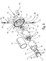
- Fig. 1
- in perspektivischer Darstellung eine erfindungsgemäße Spanneinrichtung,
- Fig. 2
- die erfindungsgemäße Spanneinrichtung in Explosivdarstellung,
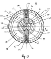
- Fig. 3
- in vergrößerter Darstellung einen Schnitt längs der Linie III-III in
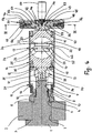
Fig. 4 , - Fig. 4
- einen Axialschnitt durch die erfindungsgemäße Spanneinrichtung, die an einen ein Werkzeug tragenden Spindelzapfen angeschlossen ist.
- Wie
Fig. 4 zeigt, sitzt auf einem Spindelzapfen 1 ein Werkzeug 2. Der Spindelzapfen 1 bildet eine Werkzeugaufnahme, auf der das Werkzeug axial gespannt wird. Hierzu ist der Spindelzapfen 1 mit einem Axialanschlag 3 versehen, an dem das Werkzeug 2 anliegt. Der Axialanschlag 3 wird beispielhaft durch eine Radialschulter gebildet, die am Spindelzapfen 1 vorgesehen ist. Der axiale Anschlag für das Werkzeug 2 kann abweichend von der dargestellten Ausführungsform jede Ausbildung haben. Die Werkzeugaufnahme ist Bestandteil einer Spindel, beispielsweise einer Frässpindel, die in bekannter Weise in einem Maschinengehäuse drehbar gelagert ist und motorisch angetrieben wird. Mit dem Werkzeug 2 werden in Holzbearbeitungsmaschinen, insbesondere Kehlmaschinen, Werkstücke bearbeitet, die insbesondere aus Holz, Kunststoff und dergleichen bestehen. Das Werkzeug 2 kann ein Profilierwerkzeug sein, mit dem beispielsweise in Kehlmaschinen oder auf Tischfräsen Profile an Werkstücken, insbesondere an länglichen Holzwerkstücken, gefräst werden. Das Werkzeug 2 kann aber beispielsweise auch ein Hobelwerkzeug sein, mit dem die Oberseite des Werkstückes gerade gehobelt wird. - Das Werkzeug 2 wird mit einer Mutter 4 unter Zwischenlage eines Sicherungsringes 5 gegen den Axialanschlag 3 gedrückt.
- Der Sicherungsring 5 sitzt auf einer zylindrischen Mantelfläche 6 des Spindelzapfens 1, die im Ausführungsbeispiel kleineren Durchmesser hat als eine zylindrische Mantelfläche 7, auf der das Werkzeug 2 sitzt. Damit das Werkzeug 2 zuverlässig axial gespannt werden kann, steht es axial in Richtung auf den Sicherungsring 5 über die Mantelfläche 7 vor. In gleicher Weise ragt auch der Sicherungsring 5 axial über die Mantelfläche 6. Der Sicherungsring 5 hat in bekannter Weise eine formschlüssige Drehverbindung zum Spindelzapfen 1, beispielsweise einen nicht dargestellten Flachkant, eine Nut- und Zapfenverbindung oder ähnliches. Damit dient er als Sicherung, dass sich die Mutter 4 nicht lösen kann, wenn vom Werkzeug 2 ein Drehmoment aufgrund von Schnitt- oder Massenträgheitskräften wirkt.
- Die Mutter 4 sitzt auf einem Gewindeabschnitt 8 des Spindelzapfens 1. Der Gewindeabschnitt 8 hat kleineren Durchmesser als die Mantelfläche 6, damit das Werkzeug 2 und der Sicherungsring 5 montiert werden können.
- Der Spindelzapfen 1 ragt axial über die Mutter 4 und ist in diesem Bereich mit einem Außenmehrkant 9, beispielsweise einem Sechskant, versehen.
- Die Mutter 4 ist an ihrer zylindrischen Außenseite mit wenigstens einer Abflachung 10 versehen. Vorteilhaft weist die Mutter 4 an ihrer Außenseite 2 diametral einander gegenüber liegende Abflachungen 10 oder einen Sechskant auf.
- Zur Spannung des Werkzeuges 2 zwischen dem Axialanschlag 3 und dem Sicherungsring 5 wird durch das Anziehen der Mutter 4 eine axiale Spannkraft erzeugt. Dafür wird auf die Mutter 4 die Spanneinrichtung so aufgesetzt, dass beim Spannvorgang eine Relativdrehung zwischen der Mutter 4 und dem Spindelzapfen 1 stattfindet. Im Ausführungsbeispiel wird die Mutter 4 in noch zu beschreibender Weise gegen Drehen festgehalten und der Spindelzapfen 1 gedreht. Die Spanneinrichtung ist so ausgebildet, dass das zur Aufbringung der axialen Spannkraft erforderliche Drehmoment einfach erzeugt werden kann. Dies erfolgt in vorteilhafter Weise im Ausführungsbeispiel vom Benutzer der Spanneinrichtung selbst, kann aber auch elektromotorisch oder über eine andere Energieform aufgebracht werden.
- Die Spanneinrichtung hat eine Hohlbuchse 11, die an einem Ende einen radial nach innen gerichteten schmalen Flansch 12 aufweist (
Fig. 4 ), mit dem sie an der Stirnseite 13 eines Getriebegehäuses 14 anliegt. Die Hohlbuchse 11 ist mittels über den Umfang des Ringflansches 12 verteilt angeordneter Schrauben 15 an der Stirnseite 13 des Getriebegehäuses 14 anliegend lösbar mit dem Getriebegehäuse verbunden. - Die Hohlbuchse 11 weist an ihrem freien Ende diametral einander gegenüberliegend zwei Abflachungen 16 auf, mit denen die Hohlbuchse 11 bei der Spannung des Werkzeuges 2 auf den Abflachungen 10 der Mutter 4 aufliegt. Im Übrigen ist die Hohlbuchse 11 zylindrisch ausgebildet.
- Im Getriebegehäuse 14 ist ein Übersetzungsgetriebe 17 untergebracht, das in
Fig. 4 lediglich schematisch dargestellt ist. Es ist vorteilhaft ein Planetengetriebe, mit dem bei kompakter Ausbildung ein hoher Übersetzungsgrad möglich ist. Im dargestellten Ausführungsbeispiel wird ein zweistufiges Planetengetriebe eingesetzt. Es hat die beiden Sonnenräder 18, 19, die auf einer Antriebswelle 20 bzw. einer Zwischenwelle 62 drehfest sitzen. Mit den Sonnenrädern 18, 19 kämmen Planetenräder 22, 23, die auf Planetenträgern 24, 25 sitzen und in Hohlräder 26, 27 eingreifen, die drehfest an der Innenseite des Getriebegehäuses 14 vorgesehen sind. Die Zwischenwelle 62 ist Bestandteil des Planetenträgers 24 bzw. fest mit diesem verbunden. - Die Abtriebswelle 21 ist Bestandteil des Planetenträgers 25.bzw. fest mit diesem verbunden.
- Über das Übersetzungsgetriebe 17 ist die Antriebswelle 20 mit der Abtriebswelle 21 antriebsverbunden.
- Die Antriebswelle 20 sowie die Abtriebswelle 21 sind in bekannter Weise im Getriebegehäuse 14 drehbar gelagert.
- Die Abtriebswelle 21 ragt aus dem Getriebegehäuse 14 in die Hohlbuchse 11, welche die Abtriebswelle 21 mit Abstand umgibt. Auf dem überstehenden Ende der Abtriebswelle 21 sitzt drehfest ein Kupplungsstück 28, das mit einem Innenmehrkant 29, vorzugsweise einem Sechskant, für den Spannvorgang auf den Außenmehrkant 9 am freien Ende des Spindelzapfens 1 geschoben wird (
Fig. 4 ). - Das Kupplungsstück 28 hat an einem Ende einen zylindrischen Ring 30, der an einer Ringschulter 31 der Abtriebswelle 21 anliegt (
Fig. 2 und4 ). Die drehfeste Verbindung zwischen dem Kupplungsstück 28 und der Abtriebswelle 21 wird vorteilhaft durch eine Feder 32 der Abtriebswelle 21 erreicht, die in eine entsprechende Axialnut in der Innenwand des Ringes 30 des Kupplungsstückes 28 eingreift. Das Kupplungsstück 28 sitzt axial gesichert auf der Abtriebswelle 21. Beispielsweise kann das Kupplungsstück 28 mittels wenigstens einer Stiftschraube 33 (Fig. 2 ) auf der Abtriebswelle 21 gesichert sein. - An den Ring 30 schließt eine Hülse 34 an, welche mit dem inneren Mehrkant 29 versehen ist. Der Ring 30 und die Hülse 34 sind vorteilhaft einstückig ausgebildet, können aber auch miteinander verschweißt sein.
- Das Getriebegehäuse 14 ist vorteilhaft mit einer Ummantelung 35 versehen, die beispielsweise aus Moosgummi besteht und eine sichere Handhabung der Spanneinrichtung für den Benutzer gewährleistet.
- Auf dem aus dem Getriebegehäuse 14 vorstehenden Ende der Antriebswelle 20 sitzt drehfest eine Rastnabe 36, die mit einem Handrad 37 gedreht werden kann. Gemäß
Fig. 4 stehen die Antriebswelle 20 und die Abtriebswelle 21 über die einander gegenüberliegenden Stirnseiten des Getriebegehäuses 14 vor. - Zur drehfesten Verbindung ist die Antriebswelle 20 mit einer Feder 38 versehen, die in eine entsprechende Nut 39 an der Innenwand der Rastnabe 36 eingreift (
Fig. 2 ). Die Rastnabe 36 weist einen endseitigen Ringflansch 40 auf, der an einem Ringflansch 41 der Antriebswelle 20 anliegt (Fig. 4 ). - Zur Axialsicherung der Rastnabe 36 auf der Antriebswelle 20 dient eine Sicherungsscheibe 42, die mittels einer Befestigungsschraube 43 an der Stirnseite der Antriebswelle 20 gehalten ist. Die Befestigungsschraube 43 wird in eine zentrale stirnseitige Gewindebohrung 44 der Antriebswelle 20 geschraubt.
- Die Sicherungsscheibe 42 greift mit ihrem Rand in eine Vertiefung 45 in der vom Getriebegehäuse 14 abgewandten Außenseite 46 des Handrades 37 ein. Dadurch wird auch das Handrad 37 durch die Sicherungsscheibe 42 axial gesichert. Vorteilhaft liegt die Sicherungsscheibe 42 vertieft in der Vertiefung 45, so dass sie beim Drehen des Handrades 37 nicht stört.
- Das Handrad 37 hat einen zylindrischen Außenmantel 47, der über einen radialen Boden 48 mit einem koaxial zu ihm verlaufenden inneren Ring 49 verbunden ist. Der Außenmantel 47, der Boden 48 und der Ring 49 sind vorteilhaft einstückig miteinander ausgebildet.
- Der Außenmantel 47 und der Ring 49 werden an zwei diametral einander gegenüberliegenden Bereichen von jeweils einer Öffnung 50, 51 durchsetzt. Die Öffnungen 50, 51 liegen fluchtend zueinander.
- Durch die Öffnungen 50, 51 wird jeweils eine Führungsbuchse 52 eingesetzt. Die Führungsbuchsen 52 können lösbar, aber auch unlösbar mit dem Handrad 37 verbunden werden. Im Ausführungsbeispiel sind sie mit einem Außengewinde versehen und in entsprechende Gewinde der Öffnungen 50, 51 geschraubt. Die Führungsbuchsen 52 sind so weit eingesetzt bzw. eingeschraubt, dass sie nicht über die Außenseite des Mantels 47 bzw. die Innenseite des Ringes 49 des Handrades 37 vorstehen.
- In den Führungsbuchsen 52 ist jeweils ein Druckbolzen 53 geführt, der an der Innenwand der Führungsbuchse 52 anliegt und unter der Kraft wenigstens einer Druckfeder 54 radial nach innen belastet wird. Der Druckbolzen 53 steht radial nach innen über die Führungsbuchse 52 vor und liegt mit seiner Stirnseite jeweils an einer ebenen Anlagefläche 55 an, die an der Außenseite der Rastnabe 36 diametral einander gegenüberliegend vorgesehen sind.
- Innerhalb der Führungsbuchsen 52 sind die Druckfedern 54 durch eine Einstellschraube 56 gesichert, die in das radial äußere Ende der Führungsbuchsen 52 geschraubt werden. Mit den Einstellschrauben 56 kann die von der Druckfeder 54 auf den Druckbolzen 53 ausgeübte Kraft stufenlos eingestellt werden.
- Die ebenen Anlageflächen 55 bilden den Boden von Vertiefungen 57, die diametral einander gegenüberliegend am Außenmantel der Rastnabe 36 vorgesehen sind. Die Anlageflächen 55 werden seitlich von einer senkrecht zu ihnen verlaufenden Seitenwand 58 begrenzt. Die Breite der Vertiefungen 57 ist etwas größer als der Durchmesser der Druckbolzen 53, der dadurch in Radialrichtung der Rastnabe 36 in der Vertiefung 57 beweglich ist. Die Anlageflächen 55 erstrecken sich bis zum Außenmantel der Rastnabe 36.
- Um das Handrad 37 einfach drehen zu können, ist es an seiner Außenseite 46 mit einer Kurbel 59 versehen.
- Um das Werkzeug 2 axial zu spannen, wird die Hohlbuchse 11 der Spanneinrichtung so auf die Mutter 4 aufgesetzt, dass die Abflachungen 10 der Hohlbuchse 11 auf die Abflachungen 10 der Mutter 4 gelangen. Diese formschlüssige, drehfeste Drehmomentkopplung hindert die Mutter 4 daran, sich relativ zur Hohlbuchse 11 bzw. der Spanneinrichtung zu drehen. Bei diesem Aufsteckvorgang gelangt der Außenmehrkant 9 des Spindelzapfens 1 in den Innenmehrkant 29 des Kupplungsstückes 28. Diese Position ist in
Fig. 4 dargestellt. Mit der Kurbel 59 wird das Handrad 37 in Pfeilrichtung 60 (Fig. 4 ) gedreht. Über die Druckbolzen 53 wird das Drehmoment vom Handrad 37 über die Anlageflächen 55 auf die Rastnabe 36 und damit auf die Antriebswelle 20 übertragen. Über das Übersetzungsgetriebe 17 wird die Abtriebswelle 21 und damit das Kupplungsstück 28 um ihre Achse gedreht. Dies hat zur Folge, dass der Spindelzapfen 1 um seine Achse gedreht wird. Da die Mutter 4 mit der Hohlbuchse 11 und der von Hand gehaltenen Spanneinrichtung formschlüssig drehverbunden ist, erfolgt eine relative Drehung zwischen Mutter 4 und Spindelzapfen 1. Dadurch erfährt die Mutter 4 über das Gewinde 8 eine Axialbewegung in Richtung auf das Werkzeug 2, wodurch der Sicherungsring 5 gegen das Werkzeug 2 gedrückt wird. Es wird dadurch zwischen dem Axialanschlag 3 und dem Sicherungsring 5 axial gespannt. - Durch das Festhalten der Spanneinrichtung durch den Benutzer wird die Mutter 4 quasi am Drehen gehindert. Zum Festhalten muss ebenfalls nur das geringe, über die Kurbel 59 eingeleitete Drehmoment aufgewendet werden.
- In manchen Fällen kann der Spindelzapfen 1 am Drehen gehindert sein, wenn beispielsweise die Frässpindel durch eine Motorbremse gehalten ist. Dann dreht sich die Spanneinrichtung zusammen mit der Mutter 4 aufgrund der notwenigen Relativdrehung von Mutter 4 und Spindelzapfen 1b beim Anziehen der Mutter.
- Da die Mutter 4 von Hand auf das Gewinde 8 des Spindelzapfens 1 geschraubt wird, bis diese am Sicherungsring 5 zur Anlage kommt, ist die Relativdrehung sehr gering.
- Infolge des Übersetzungsgetriebes 17 muss der Anwender der Spanneinrichtung keine hohen Kräfte aufbringen, um das Werkzeug 2 mit der erforderlichen Axialkraft zu spannen. So muss der Anwender lediglich ein Moment von etwa 2 Nm beim Drehen des Handrades 37 aufbringen, um das Werkzeug 2 in gefordertem Maße axial zu spannen. Das Übersetzungsgetriebe ist beispielhaft derart vorgesehen und eingebaut, dass die Drehzahl der Abtriebswelle im Verhältnis 1:50 im Vergleich zur Antriebwelle reduziert wird. Dadurch ergibt sich eine Momentenerhöhung im Verhältnis 50:1 und damit ein Abtriebs- bzw. Spannmoment von etwa 100 Nm. Das Übersetzungsverhältnis kann je nach der erforderlichen Spannkraft hiervon auch abweichen.
- Mit Hilfe der Druckfedern 54 lässt sich die axiale Spannkraft für das Werkzeug 2 sehr genau einstellen. Ist die erforderliche Axialkraft zum Einspannen des Werkzeuges 2 erreicht, führt ein weiteres Drehen des Handrades 37 dazu, dass die Druckbolzen 53 auf den Anlageflächen 55 so weit nach außen rutschen, dass sie auf den zylindrischen Außenmantel der Rastnabe 36 gelangen. Dann wird kein Drehmoment mehr vom Handrad 37 auf die Rastnabe 36 und damit auf die Antriebswelle 20 übertragen. Die Druckbolzen 53 im Zusammenwirken mit der Rastnabe 36 bilden somit eine Art Rutschkupplung, die sicherstellt, dass die Mutter 4 mit einem definierten Moment angezogen und damit das Werkzeug 2 mit einer definierten axialen Spannkraft gespannt wird.
- Um die Axialspannung des Werkzeuges 2 zu lösen, wird das Handrad 37 in Löserichtung 61 (
Fig. 4 ) gedreht. Die Druckbolzen 53 liegen dann an dem quer zur Drehrichtung liegenden Teil der Seitenwand 58 an. Diese Stellung zeigtFig. 4 . Dadurch wird beim Lösevorgang das volle Drehmoment vom Handrad 37 über die Druckbolzen 53 auf die Rastnabe 36 bzw. die Antriebswelle 20 übertragen, das heißt ohne die Wirkung der Rutschkupplung. Das Werkzeug 2 wird auf diese Weise sicher gelöst. - Anstelle der beschriebenen Ausführungsform sind auch andere Arten von Rutschkupplungen oder Einrichtungen zur Begrenzung des Drehmomentes möglich. Ebenso können andere Arten von Getrieben anstelle des beschriebenen 2-stufigen Planetengetriebes eingesetzt werden.
Claims (12)
- Spanneinrichtung zum Aufstecken auf eine auf einem Spindelzapfen (1) sitzende Mutter (4) zum axialen Spannen eines auf dem Spindelzapfen (1) sitzenden Werkzeuges (2) mittels der Mutter (4), mit einem mit wenigstens einer Betätigungseinheit (37) versehenen Kupplungsstück (28) und mit einer Drehmomentkupplung (11) für die Mutter (4), dadurch gekennzeichnet, dass das Kupplungsstück (28) mit einer Abtriebswelle (21) drehfest verbunden ist, die über ein Übersetzungsgetriebe (17) mit einer Antriebswelle (20) antriebsverbunden ist, die mit der Betätigungseinheit (37) drehfest verbunden ist.
- Spanneinrichtung nach Anspruch 1,
dadurch gekennzeichnet, dass das Übersetzungsgetriebe (17) ein Planetengetriebe ist. - Spanneinrichtung nach Anspruch 1 oder 2,
dadurch gekennzeichnet, dass die Drehmomentkopplung (11) eine Hohlbuchse ist, die mit wenigstens einer Abflachung (16) zur Anlage an wenigstens einer Abflachung (10) der Mutter (4) versehen ist. - Spanneinrichtung nach einem der Ansprüche 1 bis3,
dadurch gekennzeichnet, dass auf der Antriebswelle (20) als Betätigungseinheit ein Handrad (37) sitzt. - Spanneinrichtung nach Anspruch 4,
dadurch gekennzeichnet, dass das Handrad (37) über eine Rutschkupplung (36, 53) mit der Antriebswelle (20) verbunden ist. - Spanneinrichtung nach Anspruch 5,
dadurch gekennzeichnet, dass die Rutschkupplung eine auf der Antriebswelle (20) drehfest sitzende Nabe (36) aufweist, an der wenigstens ein Druckbolzen (53) unter Federkraft anliegt. - Spanneinrichtung nach Anspruch 6,
dadurch gekennzeichnet, dass der Druckbolzen (53) an einer Abflachung (55) am Außenmantel der Nabe (36) anliegt. - Spanneinrichtung nach Anspruch 7,
dadurch gekennzeichnet, dass die Abflachung (55) der Boden einer Vertiefung (57) am Außenmantel der Nabe (36) ist. - Spanneinrichtung nach einem der Ansprüche 6 bis 8,
dadurch gekennzeichnet, dass die Federkraft einstellbar ist. - Spanneinrichtung nach einem der Ansprüche 6 bis 9,
dadurch gekennzeichnet, dass der Druckbolzen (53) in einer Führungsbuchse (52) verschiebbar geführt ist, die im Handrad (37) untergebracht ist und mindestens eine Druckfeder (54) aufnimmt, mit der der Druckbolzen (53) in Richtung auf die Nabe (36) belastet ist. - Spanneinrichtung nach Anspruch 10,
dadurch gekennzeichnet, dass in die Führungsbuchse (52) eine Einstellschraube (56) für die Druckfeder (54) geschraubt ist. - Verwendung einer Spanneinrichtung nach einem der Ansprüche 1 bis 11 zum Spannen von Werkzeugen von Holzbearbeitungsmaschinen, insbesondere von Kehlmaschinen
Priority Applications (1)
| Application Number | Priority Date | Filing Date | Title |
|---|---|---|---|
| PL17001212T PL3279492T3 (pl) | 2016-07-29 | 2017-07-17 | Urządzenie do mocowania narzędzi |
Applications Claiming Priority (1)
| Application Number | Priority Date | Filing Date | Title |
|---|---|---|---|
| DE102016009431.1A DE102016009431A1 (de) | 2016-07-29 | 2016-07-29 | Spanneinrichtung für Werkzeuge |
Publications (2)
| Publication Number | Publication Date |
|---|---|
| EP3279492A1 EP3279492A1 (de) | 2018-02-07 |
| EP3279492B1 true EP3279492B1 (de) | 2021-11-17 |
Family
ID=59366183
Family Applications (1)
| Application Number | Title | Priority Date | Filing Date |
|---|---|---|---|
| EP17001212.4A Active EP3279492B1 (de) | 2016-07-29 | 2017-07-17 | Spanneinrichtung für werkzeuge |
Country Status (6)
| Country | Link |
|---|---|
| US (1) | US10272501B2 (de) |
| EP (1) | EP3279492B1 (de) |
| CN (1) | CN107661991B (de) |
| DE (1) | DE102016009431A1 (de) |
| PL (1) | PL3279492T3 (de) |
| TW (1) | TWI746599B (de) |
Families Citing this family (5)
| Publication number | Priority date | Publication date | Assignee | Title |
|---|---|---|---|---|
| US12000448B2 (en) * | 2019-09-20 | 2024-06-04 | Pacesetter, Inc. | Biostimulator transport system having torque limiter |
| US12544099B2 (en) * | 2021-04-01 | 2026-02-10 | Medtronic Vascular, Inc. | Tissue-removing catheter with coupled inner liner |
| CN115102095B (zh) * | 2022-07-25 | 2022-11-08 | 杭州申昊科技股份有限公司 | 一种用于配网带电作业机器人的j型线夹安装工具 |
| FR3153760B1 (fr) * | 2023-10-09 | 2025-10-24 | Lisi Aerospace | Outil d’installation d’un assemblage vis-écrou |
| ES3034925B2 (es) * | 2024-02-21 | 2026-01-23 | Sinobas Antonio Salces | Acoplamiento mecánico-hidráulico |
Citations (1)
| Publication number | Priority date | Publication date | Assignee | Title |
|---|---|---|---|---|
| DE10101093A1 (de) * | 2001-01-12 | 2002-07-25 | Ortlieb Praez S Spannzeuge Gmb | Spanneinrichtung für Werkzeuge, Werkzeughalter oder dergleichen |
Family Cites Families (18)
| Publication number | Priority date | Publication date | Assignee | Title |
|---|---|---|---|---|
| US3901519A (en) * | 1970-12-04 | 1975-08-26 | Renault | Clamping of parts by adherence on axial thrust support |
| FR2116714A5 (de) * | 1970-12-04 | 1972-07-21 | Peugeot & Renault | |
| ATE44903T1 (de) * | 1983-03-09 | 1989-08-15 | Hans Forrer | Mehrzweck-spanngeraet zur bearbeitung von werkstuecken, insbesondere von solchen aus holz. |
| JP3095981B2 (ja) * | 1995-09-07 | 2000-10-10 | 株式会社ナンドック | バイス |
| US5887860A (en) | 1997-04-08 | 1999-03-30 | Safeway Machinery Industry Corporation | Incremental multiple-forced vise of epicyclic gear train type |
| DE10130520B4 (de) * | 2001-06-25 | 2008-10-30 | Robert Bosch Gmbh | Handwerkzeugmaschine mit einer Sicherheitskupplung |
| ATE387971T1 (de) * | 2001-12-11 | 2008-03-15 | Mario Fabris | Antriebswelle mit in zwei stufen arbeitender spannvorrichtung |
| DE102004011738B4 (de) * | 2004-03-03 | 2010-01-07 | Michael Weinig Ag | Vorrichtung mit einer Löseeinheit zum Betätigen einer Spannvorrichtung für Werkzeuge |
| US7331584B2 (en) * | 2004-09-17 | 2008-02-19 | Black & Decker Inc. | Chuck with nutating gear reduction |
| DE102011055869A1 (de) * | 2011-11-30 | 2013-06-06 | Röhm Gmbh | Bohrvorrichtung |
| DE102012100821A1 (de) * | 2012-02-01 | 2013-08-01 | Röhm Gmbh | Spannfutter |
| DE102012213724B4 (de) * | 2012-03-26 | 2023-11-30 | Robert Bosch Gmbh | Planetengetriebe für eine Handwerkzeugmaschine |
| DE102012209312A1 (de) * | 2012-06-01 | 2013-12-05 | Gühring Ohg | Modularer Werkzeughalter |
| TWM459094U (zh) * | 2013-03-19 | 2013-08-11 | Maho Entpr Co Ltd | 工具夾持裝置 |
| DE102013111731A1 (de) * | 2013-10-24 | 2015-04-30 | Röhm Gmbh | Bohrfutter |
| CN203843263U (zh) * | 2014-02-28 | 2014-09-24 | 贵州劲锋精密工具有限公司 | 刀具夹紧装置 |
| CN203992221U (zh) * | 2014-08-21 | 2014-12-10 | 东莞华辉数控机床有限公司 | 一种可快速换刀按钮式旋转夹紧装置 |
| DE102015110405B3 (de) * | 2015-06-29 | 2016-06-30 | Putsch Gmbh & Co. Kg | Maschinell betriebene Vorrichtung, insbesondere Fräsvorrichtung |
-
2016
- 2016-07-29 DE DE102016009431.1A patent/DE102016009431A1/de not_active Withdrawn
-
2017
- 2017-07-17 PL PL17001212T patent/PL3279492T3/pl unknown
- 2017-07-17 EP EP17001212.4A patent/EP3279492B1/de active Active
- 2017-07-19 TW TW106124133A patent/TWI746599B/zh active
- 2017-07-28 CN CN201710626594.0A patent/CN107661991B/zh active Active
- 2017-07-28 US US15/662,600 patent/US10272501B2/en active Active
Patent Citations (1)
| Publication number | Priority date | Publication date | Assignee | Title |
|---|---|---|---|---|
| DE10101093A1 (de) * | 2001-01-12 | 2002-07-25 | Ortlieb Praez S Spannzeuge Gmb | Spanneinrichtung für Werkzeuge, Werkzeughalter oder dergleichen |
Also Published As
| Publication number | Publication date |
|---|---|
| TWI746599B (zh) | 2021-11-21 |
| EP3279492A1 (de) | 2018-02-07 |
| CN107661991A (zh) | 2018-02-06 |
| TW201806691A (zh) | 2018-03-01 |
| US20180029138A1 (en) | 2018-02-01 |
| DE102016009431A1 (de) | 2018-02-01 |
| CN107661991B (zh) | 2021-04-06 |
| PL3279492T3 (pl) | 2022-04-11 |
| US10272501B2 (en) | 2019-04-30 |
Similar Documents
| Publication | Publication Date | Title |
|---|---|---|
| EP0330672B1 (de) | Spanneinrichtung zum axialen festspannen eines werkzeuges, insbesondere einer scheibe | |
| EP1307313B1 (de) | Handwerkzeugmaschine | |
| EP1109642B1 (de) | Spannfutter, insbesondere dehnspannfutter | |
| DE102006001986A1 (de) | Spannvorrichtung zum lösbaren Befestigen eines scheibenförmigen Werkzeugs | |
| EP3708753B1 (de) | Deckelbeschlag zum schwenkbaren befestigen eines deckels an einen möbelkorpus | |
| EP3279492A1 (de) | Spanneinrichtung für werkzeuge | |
| EP3411185B1 (de) | Spannvorrichtung | |
| EP1952947B1 (de) | Kraftgetriebenes Handwerkzeug zum Bohren und/oder Schrauben | |
| EP1995024B1 (de) | Handgeführtes Arbeitsgerät | |
| WO1988004219A1 (fr) | Outillage a main portatif, notamment meuleuse d'angle | |
| DE102013113868A1 (de) | Bohrvorrichtung und Bohrfutter | |
| EP0239670B1 (de) | Motorgetriebene Maschine mit Drehmomenteinstellung, insbesondere elektrisches Handwerkzeug | |
| DE102015122699B4 (de) | Spannklaue | |
| EP2006058B1 (de) | Spanneinrichtung zum werkzeuglosen Festspannen | |
| DE102016006340B4 (de) | Lochsägeneinrichtung mit Auswerfer | |
| DE102012206285A1 (de) | Bearbeitungsmaschine in Ständerbauart | |
| EP2210709A2 (de) | Stützfuß für Kraftschrauber | |
| DE102014104367A1 (de) | Bohrvorrichtung und Rutschkupplung für eine Bohrvorrichtung | |
| EP0697268A1 (de) | Vorrichtung zur lösbaren Festlegung eines zu Verstellzwecken verdrehbaren Handgriffes | |
| DE10239483B3 (de) | Handwerkzeugmaschine, beispielsweise Schrauber | |
| DE9305188U1 (de) | Schnellspannvorrichtung für Stichsägeblätter | |
| DE3731026C2 (de) | ||
| DE102010031805B3 (de) | Hakenschlüssel zur Arretierung einer Werkzeugaufnahme | |
| DE10260493A1 (de) | Kraftspannfutter und Ausklinkschlüssel dafür | |
| DE102013216516B4 (de) | Handwerkzeugmaschinenwerkzeugaufnahme |
Legal Events
| Date | Code | Title | Description |
|---|---|---|---|
| PUAI | Public reference made under article 153(3) epc to a published international application that has entered the european phase |
Free format text: ORIGINAL CODE: 0009012 |
|
| STAA | Information on the status of an ep patent application or granted ep patent |
Free format text: STATUS: THE APPLICATION HAS BEEN PUBLISHED |
|
| AK | Designated contracting states |
Kind code of ref document: A1 Designated state(s): AL AT BE BG CH CY CZ DE DK EE ES FI FR GB GR HR HU IE IS IT LI LT LU LV MC MK MT NL NO PL PT RO RS SE SI SK SM TR |
|
| AX | Request for extension of the european patent |
Extension state: BA ME |
|
| STAA | Information on the status of an ep patent application or granted ep patent |
Free format text: STATUS: REQUEST FOR EXAMINATION WAS MADE |
|
| 17P | Request for examination filed |
Effective date: 20180807 |
|
| RBV | Designated contracting states (corrected) |
Designated state(s): AL AT BE BG CH CY CZ DE DK EE ES FI FR GB GR HR HU IE IS IT LI LT LU LV MC MK MT NL NO PL PT RO RS SE SI SK SM TR |
|
| STAA | Information on the status of an ep patent application or granted ep patent |
Free format text: STATUS: EXAMINATION IS IN PROGRESS |
|
| 17Q | First examination report despatched |
Effective date: 20200525 |
|
| GRAP | Despatch of communication of intention to grant a patent |
Free format text: ORIGINAL CODE: EPIDOSNIGR1 |
|
| STAA | Information on the status of an ep patent application or granted ep patent |
Free format text: STATUS: GRANT OF PATENT IS INTENDED |
|
| INTG | Intention to grant announced |
Effective date: 20210604 |
|
| GRAS | Grant fee paid |
Free format text: ORIGINAL CODE: EPIDOSNIGR3 |
|
| GRAA | (expected) grant |
Free format text: ORIGINAL CODE: 0009210 |
|
| STAA | Information on the status of an ep patent application or granted ep patent |
Free format text: STATUS: THE PATENT HAS BEEN GRANTED |
|
| AK | Designated contracting states |
Kind code of ref document: B1 Designated state(s): AL AT BE BG CH CY CZ DE DK EE ES FI FR GB GR HR HU IE IS IT LI LT LU LV MC MK MT NL NO PL PT RO RS SE SI SK SM TR |
|
| REG | Reference to a national code |
Ref country code: GB Ref legal event code: FG4D Free format text: NOT ENGLISH |
|
| REG | Reference to a national code |
Ref country code: IE Ref legal event code: FG4D Free format text: LANGUAGE OF EP DOCUMENT: GERMAN |
|
| REG | Reference to a national code |
Ref country code: DE Ref legal event code: R096 Ref document number: 502017012015 Country of ref document: DE |
|
| REG | Reference to a national code |
Ref country code: AT Ref legal event code: REF Ref document number: 1448297 Country of ref document: AT Kind code of ref document: T Effective date: 20211215 |
|
| REG | Reference to a national code |
Ref country code: NL Ref legal event code: FP |
|
| REG | Reference to a national code |
Ref country code: LT Ref legal event code: MG9D |
|
| PG25 | Lapsed in a contracting state [announced via postgrant information from national office to epo] |
Ref country code: RS Free format text: LAPSE BECAUSE OF FAILURE TO SUBMIT A TRANSLATION OF THE DESCRIPTION OR TO PAY THE FEE WITHIN THE PRESCRIBED TIME-LIMIT Effective date: 20211117 Ref country code: LT Free format text: LAPSE BECAUSE OF FAILURE TO SUBMIT A TRANSLATION OF THE DESCRIPTION OR TO PAY THE FEE WITHIN THE PRESCRIBED TIME-LIMIT Effective date: 20211117 Ref country code: FI Free format text: LAPSE BECAUSE OF FAILURE TO SUBMIT A TRANSLATION OF THE DESCRIPTION OR TO PAY THE FEE WITHIN THE PRESCRIBED TIME-LIMIT Effective date: 20211117 Ref country code: BG Free format text: LAPSE BECAUSE OF FAILURE TO SUBMIT A TRANSLATION OF THE DESCRIPTION OR TO PAY THE FEE WITHIN THE PRESCRIBED TIME-LIMIT Effective date: 20220217 |
|
| PG25 | Lapsed in a contracting state [announced via postgrant information from national office to epo] |
Ref country code: IS Free format text: LAPSE BECAUSE OF FAILURE TO SUBMIT A TRANSLATION OF THE DESCRIPTION OR TO PAY THE FEE WITHIN THE PRESCRIBED TIME-LIMIT Effective date: 20220317 Ref country code: SE Free format text: LAPSE BECAUSE OF FAILURE TO SUBMIT A TRANSLATION OF THE DESCRIPTION OR TO PAY THE FEE WITHIN THE PRESCRIBED TIME-LIMIT Effective date: 20211117 Ref country code: PT Free format text: LAPSE BECAUSE OF FAILURE TO SUBMIT A TRANSLATION OF THE DESCRIPTION OR TO PAY THE FEE WITHIN THE PRESCRIBED TIME-LIMIT Effective date: 20220317 Ref country code: NO Free format text: LAPSE BECAUSE OF FAILURE TO SUBMIT A TRANSLATION OF THE DESCRIPTION OR TO PAY THE FEE WITHIN THE PRESCRIBED TIME-LIMIT Effective date: 20220217 Ref country code: LV Free format text: LAPSE BECAUSE OF FAILURE TO SUBMIT A TRANSLATION OF THE DESCRIPTION OR TO PAY THE FEE WITHIN THE PRESCRIBED TIME-LIMIT Effective date: 20211117 Ref country code: HR Free format text: LAPSE BECAUSE OF FAILURE TO SUBMIT A TRANSLATION OF THE DESCRIPTION OR TO PAY THE FEE WITHIN THE PRESCRIBED TIME-LIMIT Effective date: 20211117 Ref country code: GR Free format text: LAPSE BECAUSE OF FAILURE TO SUBMIT A TRANSLATION OF THE DESCRIPTION OR TO PAY THE FEE WITHIN THE PRESCRIBED TIME-LIMIT Effective date: 20220218 Ref country code: ES Free format text: LAPSE BECAUSE OF FAILURE TO SUBMIT A TRANSLATION OF THE DESCRIPTION OR TO PAY THE FEE WITHIN THE PRESCRIBED TIME-LIMIT Effective date: 20211117 |
|
| PG25 | Lapsed in a contracting state [announced via postgrant information from national office to epo] |
Ref country code: SM Free format text: LAPSE BECAUSE OF FAILURE TO SUBMIT A TRANSLATION OF THE DESCRIPTION OR TO PAY THE FEE WITHIN THE PRESCRIBED TIME-LIMIT Effective date: 20211117 Ref country code: SK Free format text: LAPSE BECAUSE OF FAILURE TO SUBMIT A TRANSLATION OF THE DESCRIPTION OR TO PAY THE FEE WITHIN THE PRESCRIBED TIME-LIMIT Effective date: 20211117 Ref country code: RO Free format text: LAPSE BECAUSE OF FAILURE TO SUBMIT A TRANSLATION OF THE DESCRIPTION OR TO PAY THE FEE WITHIN THE PRESCRIBED TIME-LIMIT Effective date: 20211117 Ref country code: EE Free format text: LAPSE BECAUSE OF FAILURE TO SUBMIT A TRANSLATION OF THE DESCRIPTION OR TO PAY THE FEE WITHIN THE PRESCRIBED TIME-LIMIT Effective date: 20211117 Ref country code: DK Free format text: LAPSE BECAUSE OF FAILURE TO SUBMIT A TRANSLATION OF THE DESCRIPTION OR TO PAY THE FEE WITHIN THE PRESCRIBED TIME-LIMIT Effective date: 20211117 Ref country code: CZ Free format text: LAPSE BECAUSE OF FAILURE TO SUBMIT A TRANSLATION OF THE DESCRIPTION OR TO PAY THE FEE WITHIN THE PRESCRIBED TIME-LIMIT Effective date: 20211117 |
|
| REG | Reference to a national code |
Ref country code: DE Ref legal event code: R097 Ref document number: 502017012015 Country of ref document: DE |
|
| PLBE | No opposition filed within time limit |
Free format text: ORIGINAL CODE: 0009261 |
|
| STAA | Information on the status of an ep patent application or granted ep patent |
Free format text: STATUS: NO OPPOSITION FILED WITHIN TIME LIMIT |
|
| 26N | No opposition filed |
Effective date: 20220818 |
|
| PG25 | Lapsed in a contracting state [announced via postgrant information from national office to epo] |
Ref country code: AL Free format text: LAPSE BECAUSE OF FAILURE TO SUBMIT A TRANSLATION OF THE DESCRIPTION OR TO PAY THE FEE WITHIN THE PRESCRIBED TIME-LIMIT Effective date: 20211117 |
|
| PG25 | Lapsed in a contracting state [announced via postgrant information from national office to epo] |
Ref country code: SI Free format text: LAPSE BECAUSE OF FAILURE TO SUBMIT A TRANSLATION OF THE DESCRIPTION OR TO PAY THE FEE WITHIN THE PRESCRIBED TIME-LIMIT Effective date: 20211117 |
|
| PG25 | Lapsed in a contracting state [announced via postgrant information from national office to epo] |
Ref country code: MC Free format text: LAPSE BECAUSE OF FAILURE TO SUBMIT A TRANSLATION OF THE DESCRIPTION OR TO PAY THE FEE WITHIN THE PRESCRIBED TIME-LIMIT Effective date: 20211117 |
|
| PG25 | Lapsed in a contracting state [announced via postgrant information from national office to epo] |
Ref country code: LU Free format text: LAPSE BECAUSE OF NON-PAYMENT OF DUE FEES Effective date: 20220717 |
|
| PG25 | Lapsed in a contracting state [announced via postgrant information from national office to epo] |
Ref country code: IE Free format text: LAPSE BECAUSE OF NON-PAYMENT OF DUE FEES Effective date: 20220717 |
|
| P01 | Opt-out of the competence of the unified patent court (upc) registered |
Effective date: 20230906 |
|
| PG25 | Lapsed in a contracting state [announced via postgrant information from national office to epo] |
Ref country code: HU Free format text: LAPSE BECAUSE OF FAILURE TO SUBMIT A TRANSLATION OF THE DESCRIPTION OR TO PAY THE FEE WITHIN THE PRESCRIBED TIME-LIMIT; INVALID AB INITIO Effective date: 20170717 |
|
| PG25 | Lapsed in a contracting state [announced via postgrant information from national office to epo] |
Ref country code: MK Free format text: LAPSE BECAUSE OF FAILURE TO SUBMIT A TRANSLATION OF THE DESCRIPTION OR TO PAY THE FEE WITHIN THE PRESCRIBED TIME-LIMIT Effective date: 20211117 Ref country code: CY Free format text: LAPSE BECAUSE OF FAILURE TO SUBMIT A TRANSLATION OF THE DESCRIPTION OR TO PAY THE FEE WITHIN THE PRESCRIBED TIME-LIMIT Effective date: 20211117 |
|
| PG25 | Lapsed in a contracting state [announced via postgrant information from national office to epo] |
Ref country code: MT Free format text: LAPSE BECAUSE OF FAILURE TO SUBMIT A TRANSLATION OF THE DESCRIPTION OR TO PAY THE FEE WITHIN THE PRESCRIBED TIME-LIMIT Effective date: 20211117 |
|
| PGFP | Annual fee paid to national office [announced via postgrant information from national office to epo] |
Ref country code: PL Payment date: 20250624 Year of fee payment: 9 |
|
| PGFP | Annual fee paid to national office [announced via postgrant information from national office to epo] |
Ref country code: GB Payment date: 20250623 Year of fee payment: 9 |
|
| PGFP | Annual fee paid to national office [announced via postgrant information from national office to epo] |
Ref country code: FR Payment date: 20250626 Year of fee payment: 9 |
|
| PGFP | Annual fee paid to national office [announced via postgrant information from national office to epo] |
Ref country code: NL Payment date: 20250724 Year of fee payment: 9 |
|
| PGFP | Annual fee paid to national office [announced via postgrant information from national office to epo] |
Ref country code: DE Payment date: 20250926 Year of fee payment: 9 |
|
| PGFP | Annual fee paid to national office [announced via postgrant information from national office to epo] |
Ref country code: IT Payment date: 20250709 Year of fee payment: 9 |
|
| PGFP | Annual fee paid to national office [announced via postgrant information from national office to epo] |
Ref country code: BE Payment date: 20250728 Year of fee payment: 9 |
|
| PGFP | Annual fee paid to national office [announced via postgrant information from national office to epo] |
Ref country code: AT Payment date: 20250718 Year of fee payment: 9 |
|
| PGFP | Annual fee paid to national office [announced via postgrant information from national office to epo] |
Ref country code: CH Payment date: 20250801 Year of fee payment: 9 |
|
| PG25 | Lapsed in a contracting state [announced via postgrant information from national office to epo] |
Ref country code: TR Free format text: LAPSE BECAUSE OF FAILURE TO SUBMIT A TRANSLATION OF THE DESCRIPTION OR TO PAY THE FEE WITHIN THE PRESCRIBED TIME-LIMIT Effective date: 20211117 |