EP3279375A1 - Procédé pour fabriquer un agrégat de nanotubes de carbone - Google Patents
Procédé pour fabriquer un agrégat de nanotubes de carbone Download PDFInfo
- Publication number
- EP3279375A1 EP3279375A1 EP16772456.6A EP16772456A EP3279375A1 EP 3279375 A1 EP3279375 A1 EP 3279375A1 EP 16772456 A EP16772456 A EP 16772456A EP 3279375 A1 EP3279375 A1 EP 3279375A1
- Authority
- EP
- European Patent Office
- Prior art keywords
- carbon nanotube
- yarns
- carbon
- liquid
- roller
- Prior art date
- Legal status (The legal status is an assumption and is not a legal conclusion. Google has not performed a legal analysis and makes no representation as to the accuracy of the status listed.)
- Withdrawn
Links
Images


Classifications
-
- C—CHEMISTRY; METALLURGY
- C01—INORGANIC CHEMISTRY
- C01B—NON-METALLIC ELEMENTS; COMPOUNDS THEREOF; METALLOIDS OR COMPOUNDS THEREOF NOT COVERED BY SUBCLASS C01C
- C01B32/00—Carbon; Compounds thereof
- C01B32/15—Nano-sized carbon materials
- C01B32/158—Carbon nanotubes
- C01B32/16—Preparation
- C01B32/164—Preparation involving continuous processes
-
- D—TEXTILES; PAPER
- D02—YARNS; MECHANICAL FINISHING OF YARNS OR ROPES; WARPING OR BEAMING
- D02G—CRIMPING OR CURLING FIBRES, FILAMENTS, THREADS, OR YARNS; YARNS OR THREADS
- D02G3/00—Yarns or threads, e.g. fancy yarns; Processes or apparatus for the production thereof, not otherwise provided for
- D02G3/02—Yarns or threads characterised by the material or by the materials from which they are made
- D02G3/16—Yarns or threads made from mineral substances
-
- C—CHEMISTRY; METALLURGY
- C01—INORGANIC CHEMISTRY
- C01B—NON-METALLIC ELEMENTS; COMPOUNDS THEREOF; METALLOIDS OR COMPOUNDS THEREOF NOT COVERED BY SUBCLASS C01C
- C01B32/00—Carbon; Compounds thereof
- C01B32/15—Nano-sized carbon materials
- C01B32/158—Carbon nanotubes
- C01B32/168—After-treatment
-
- D—TEXTILES; PAPER
- D01—NATURAL OR MAN-MADE THREADS OR FIBRES; SPINNING
- D01F—CHEMICAL FEATURES IN THE MANUFACTURE OF ARTIFICIAL FILAMENTS, THREADS, FIBRES, BRISTLES OR RIBBONS; APPARATUS SPECIALLY ADAPTED FOR THE MANUFACTURE OF CARBON FILAMENTS
- D01F9/00—Artificial filaments or the like of other substances; Manufacture thereof; Apparatus specially adapted for the manufacture of carbon filaments
- D01F9/08—Artificial filaments or the like of other substances; Manufacture thereof; Apparatus specially adapted for the manufacture of carbon filaments of inorganic material
- D01F9/12—Carbon filaments; Apparatus specially adapted for the manufacture thereof
-
- C—CHEMISTRY; METALLURGY
- C01—INORGANIC CHEMISTRY
- C01B—NON-METALLIC ELEMENTS; COMPOUNDS THEREOF; METALLOIDS OR COMPOUNDS THEREOF NOT COVERED BY SUBCLASS C01C
- C01B2202/00—Structure or properties of carbon nanotubes
- C01B2202/08—Aligned nanotubes
Definitions
- the present invention relates to a method for manufacturing a carbon nanotube collected product.
- Densification of such carbon nanotube yarns is desired in order to further improve thermal conductivity and electrical conductivity Further, from a viewpoint of manufacturing efficiency, various methods for densifying a plurality of carbon nanotube yarns at one time have been studied
- a method for manufacturing a carbon nanotube sheet comprises the steps of: drawing a plurality of nanofibers (a carbon nanotube sheet) from a carbon nanotube forest located on a substrate and pasting them on a substrate film; immersing them in a liquid or supplying liquid steam to them to achieve the densification of the plurality of nanofibers; and then rolling up the plurality of nanofibers which are pasted on the substrate film on a mandrel.
- Patent Document 1 Japanese Patent Application Publication No. 2013-174038
- the first aspect of the present invention includes a method for manufacturing a carbon nanotube collected product, comprising the steps of: preparing a roller, the roller comprising a shaft having a cylindrical shape and a resin film located over an entire circumference of the shaft; preparing a plurality of carbon nanotube yarns each having a plurality of carbon nanotubes; arranging the plurality of carbon nanotube yarns in parallel and along a direction an axis of the shaft extends, and drawing the plurality of carbon nanotube yarns in a circumferential direction of the shaft such that the plurality of carbon nanotube yarns are located on the resin film; supplying a volatile liquid to the plurality of carbon nanotube yarns located on the resin film; and processing the plurality of carbon nanotube yarns to which the liquid has been supplied
- the carbon nanotube yarns may move due to the surface tension, etc., of the liquid, and thus the orientation of the plurality of carbon nanotube yarns may be disarranged
- the plurality of carbon nanotube yarns which are arranged in parallel may be prevented from moving in the axial direction due to the friction between the resin film and the carbon nanotube yarns because the volatile liquid is supplied to the plurality of carbon nanotube yarns located on the resin film.
- the disarrangement of the orientations of the plurality of carbon nanotube yarns may be suppressed
- the plurality of carbon nanotube yarns may be densified at one time.
- the plurality of carbon nanotube yarns which have been densified may be separated from the resin film because the roller is equipped with the resin film.
- the plurality of carbon nanotube yarns may be smoothly processed and thus the manufacturing efficiency of the carbon nanotube collected product may be improved
- the second aspect of the present invention includes the method for manufacturing a carbon nanotube collected product according to the first aspect, wherein in the step of supplying the liquid to the plurality of carbon nanotube yarns, the liquid is sprayed to the plurality of carbon nanotube yarns located on the resin film.
- the liquid When a liquid is supplied to a plurality of carbon nanotube yarns by immersing them in the liquid, the liquid may be excessively supplied to the plurality of carbon nanotube yarns.
- the plurality of carbon nanotube yarns which are arranged in parallel may move due to the surface tension, etc., of the liquid, and thus carbon nanotube yarns adjacent to each other may be attached to each other. Thus, it is difficult to ensure the orientations of the plurality of carbon nanotube yarns.
- the amount of the liquid supplied to a plurality of carbon nanotube yarns may be adjusted more readily than in a case where a plurality of carbon nanotube yarns are immersed in a liquid, because the liquid is sprayed to the plurality of carbon nanotube yarns which are located on a resin film.
- the orientations of the plurality of carbon nanotube yarns may be reliably ensured
- the third aspect of the present invention includes the method for manufacturing a carbon nanotube collected product according to the second aspect, wherein in the step of supplying the liquid to the plurality of carbon nanotube yarns, a restricting member is located such that the restricting member prevents the liquid from being sprayed to the plurality of carbon nanotube yarns which are not located on the resin film.
- the disarrangement of the orientations of the plurality of carbon nanotube yarns may be reliably suppressed because the restricting member prevents the liquid from being sprayed to the plurality of carbon nanotube yarns which are not located on the resin film.
- the fourth aspect of the present invention includes the method for manufacturing a carbon nanotube collected product according to the third aspect, wherein in the step of supplying the liquid to the plurality of carbon nanotube yarns, the restricting member is located such that the liquid is sprayed over an area around the shaft with a central angle from 5 to 150 degrees.
- the amount of the liquid adhered to a plurality of carbon nanotube yarns may be uneven.
- the plurality of carbon nanotube yarns have an uneven density due to the difference of the amount of the adhered liquid
- the restricting member allows a liquid to be sprayed over an area around the shaft with a central angle from 5 to 150 degrees while the restricting member prevents the liquid from being sprayed to the other regions.
- the volatile liquid may be uniformly sprayed to the plurality of carbon nanotube yarns which are located on the resin film, and thus the amount of the adhered liquid may be uniformed As a result, the density of the plurality of carbon nanotube yarns may be uniformed
- the fine particles or the resin material may be attached to the plurality of carbon nanotube yarns when the liquid is sprayed to the plurality of carbon nanotube yarns, because the fine particles are dispersed in the liquid or the resin material is dissolved in the liquid
- the properties of the fine particles and/or the resin material may be provided to the carbon nanotube collected product which is processed from a plurality of carbon nanotube yarns.
- the sixth aspect of the present invention includes the method for manufacturing a carbon nanotube collected product according to any one of the first to fifth aspects, wherein each of the carbon nanotube yarns is a carbon nanotube single yarn comprising a plurality of carbon nanotubes which are continuously connected in an extension direction of each of the carbon nanotube yarns.
- the plurality of carbon nanotubes are oriented along the extension direction of the carbon nanotube single yarn because the plurality of carbon nanotubes are continuously connected along the extension direction of the carbon nanotube yarn.
- the orientations of the carbon nanotubes may be reliably ensured, and eventually, in the carbon nanotube collected product, the orientations of the carbon nanotubes may be reliably ensured
- the seventh aspect of the present invention includes the method for manufacturing a carbon nanotube collected product according to the sixth aspect, wherein, in the step of processing the plurality of carbon nanotube yarns, the plurality of carbon nanotube single yarns to which the liquid has been sprayed are drawn from the roller and then twisted together into a twisted yarn.
- the plurality of carbon nanotube single yarns may be smoothly processed, and the twisted yarns may be manufactured
- the productivity of the twisted yarns may be improved.
- the eighth aspect of the present invention includes the method for manufacturing a carbon nanotube collected product according to any one of the first to sixth aspects, wherein, in the step of drawing the plurality of carbon nanotube yarns onto the shaft, the plurality of carbon nanotube yarns are wound around a circumferential surface of the roller for a plurality of turns, and wherein, in the step of processing the plurality of carbon nanotube yarns, the plurality of carbon nanotube yarns wound around the circumferential surface of the roller for a plurality of turns are cut along the direction the axis of the shaft extends into a sheet shape.
- the plurality of carbon nanotube yarns are sequentially wound around the roller after the volatile liquid is sprayed to the plurality of carbon nanotube yarns.
- the volatile liquid is sprayed to the plurality of carbon nanotube yarns after the plurality of carbon nanotube yarns are located on the plurality of carbon nanotube yarns which have already been wound around the roller.
- the plurality of outer carbon nanotube yarns which are exposed on the surface are prevented from moving in the axial direction due to the friction against the plurality of inner carbon nanotube yarns.
- each of the carbon nanotube yarns may have an improved density due to the evaporation of the volatile liquid
- the plurality of carbon-nanotube stacked yarns may aggregate to each other in a radial direction of the shaft.
- the density of the plurality of carbon nanotube yarns which are wound around the roller for a plurality of turns may be improved
- the productivity of the carbon-nanotube stacked sheet may be improved.
- a plurality of carbon nanotube yarns may be densified at one time, a plurality of carbon nanotube yarns may be smoothly processed, and the manufacturing efficiency of carbon nanotube collected products may be improved
- the method for manufacturing a carbon nanotube collected product of the present invention comprises the steps of: preparing a roller 2; preparing a plurality of carbon nanotube single yarns 1 which is an example of the carbon nanotube yarn; drawing the plurality of carbon nanotube single yarns 1 to a circumferential surface of the roller 2; spraying a liquid to the plurality of carbon nanotube single yarns 1 located on the roller 2; and processing the plurality of carbon nanotube single yarns 1.
- the roller 2 comprises a roller body 15, which is an example of the shaft, and a resin film 16.
- the roller body 15 is made of a metal and has a cylindrical shape extending in a predetermined direction.
- the predetermined direction in which the roller body 15 extends will be referred to as the left-right direction which is an example of the axial direction.
- the direction orthogonal to the left-right direction will be referred to as the front-back direction.
- the directions are based on the arrows shown in each of the figures.
- the size of the roller body 15 is not particularly limited
- the roller body 15 may have an outer diameter of, for example, from 1 cm to 20 cm.
- the size of the roller body 15 in the left-right direction is, for example, from 1 cm to 100 cm.
- the roller body 15 is configured to rotate around its axis line as the rotational center.
- the resin film 16 is located on the circumferential surface of the roller body 15 so as to cover the entire circumference of the roller body 15.
- the resin film 16 may have a thickness of, for example, from 1 ⁇ m to 1,000 ⁇ m.
- the resin film 16 may be located over the entirety of the roller body 15 or may be located on only a part of the roller body 15.
- the resin film 16 is located at such a position that the resin film 16 is opposed to the opening 19A of the restricting board 19 described below.
- the resin film 16 is preferably located substantially at the center of the roller body 15 in the left-right direction.
- the size of the resin film 16 in the left-right direction is, for example, from 20% to 80% of the size of the roller body 15 in the left-right direction set at 100%.
- the resin film 16 is formed from a resin to a film shape.
- the resin may be, for example, a thermoplastic resin, a thermosetting resin, etc.
- the thermoplastic resin may be, for example, a polyester resin (polyethylene terephthalate, polyethylene naphthalate, etc.), a polycarbonate resin, a fluorine resin (for example, an ethylene-tetrafluoroethylene copolymer, polytetrafluoroethylene, perfluoroalkoxyalkane, a perfluoroethylene-propene copolymer, polyvinylidenefluoride, etc.).
- a polyester resin polyethylene terephthalate, polyethylene naphthalate, etc.
- a fluorine resin for example, an ethylene-tetrafluoroethylene copolymer, polytetrafluoroethylene, perfluoroalkoxyalkane, a perfluoroethylene-propene copolymer, polyvinylidenefluoride, etc.
- thermoplastic resin is preferable, and a fluorine resin is more preferable, and polytetrafluoroethylene is particularly preferable.
- a plurality of vertically aligned carbon nanotubes 3 are grown on a substrate 9 by chemical vapor deposition method (CVD method), and then a plurality of carbon nanotube single yarns 1 are drawn from the plurality of carbon nanotubes 3.
- CVD method chemical vapor deposition method
- a substrate 9 is prepared
- the substrate 9 is not particularly limited
- the substrate 9 may be, for example, a publicly known substrate which is used for a CVD method
- a commercially available item may also be used as the substrate 9.
- the substrate 9 may be a silicon substrate, a stainless steel substrate 12 on which a silicon dioxide film 11 is stacked, etc., and may preferably be a stainless steel substrate 12 on which a silicon dioxide film 11 is stacked
- Figs. 1A to 1D and Fig. 2 show a case where the substrate 9 is a stainless steel substrate 12 on which a silicon dioxide film 11 is stacked
- a catalyst layer 13 is formed on the substrate 9, preferably on the silicon dioxide film 11.
- a film of a metal catalyst may be formed by a publicly known film-forming method on the substrate 9 (preferably on the silicon dioxide film 11).
- the metal catalyst may be, for example, iron, cobalt, nickel, etc., and iron is preferable. Such a metal catalyst may be used singly, or a plurality of kinds of metal catalysts may be used together.
- the film-forming method may be, for example, vacuum deposition and sputtering, and vacuum deposition is preferable.
- the substrate 9 on which the catalyst layer 13 is located is heated to a temperature of from 700°C to 900°C, as shown in Fig. 1B .
- the catalyst layer 13 is aggregated to be a plurality of granular bodies 13A.
- the source gas may also contain hydrogen gas, inert gas (for example, helium, argon, etc.), water vapor, etc., as necessary.
- inert gas for example, helium, argon, etc.
- the concentration of the hydrocarbon gas in the source gas may be, for example, from 1 volume %, or preferably 30 volume %, to 90 volume %, or preferably 50 volume %.
- the supply time of the source gas may be, for example, from 1 minute, or preferably 5 minutes, to 60 minutes, or preferably 30 minutes.
- the plurality of carbon nanotubes 3 grow from the plurality of granular bodies 13A.
- Fig. 1C shows one carbon nanotube 3 grows from one granular body 13A.
- the present invention is not limited to this.
- a plurality of carbon nanotubes 3 may grow from one granular body 13A.
- the carbon nanotubes 3 which are located in the longitudinal end of each of the rows 10A in the carbon nanotube array 10 are collectively held by a drawing device (not shown) and then are pulled in a direction which intersects the thickness direction of the substrate 9, preferably in the front-back direction.
- the carbon nanotubes 3 whose one ends (lower ends) are attached to the drawn carbon nanotubes 3 are tilted when the one ends (lower ends) are pulled downstream in the drawing direction such that the other ends (upper ends) of the tilted carbon nanotubes 3 move upstream in the drawing direction and thus are attached to the other ends (upper ends) of adjacent carbon nanotubes 3.
- Each of the plurality of carbon nanotube single yarns 1 is an untwisted yarn which is not twisted and has a yarn shape (linear shape). That is, the twist angle of each of the carbon nanotube single yarns 1 is substantially 0 degree.
- the plurality of carbon nanotubes 3 are each linearly and continuously connected with each other in the extension direction. That is, the plurality of carbon nanotubes 3 are oriented along the extension direction of the carbon nanotube single yarns 1.
- Fig. 1D shows that carbon nanotubes 3 are continuously connected one by one to thereby form a carbon nanotube single yarn 1.
- the carbon nanotube single yarn 1 is formed of continuously connected bundles comprising the plurality of carbon nanotubes 3.
- the plurality of carbon nanotube single yarns 1 are arranged in parallel in a direction which intersects the extension direction of the carbon nanotube single yarns 1 because the carbon nanotubes 3 of the rows 10A are drawn in parallel (see the enlargement in Fig. 2 ).
- the carbon nanotube single yarns 1 extend along the front-back direction and, as shown in Fig. 3B , the plurality of carbon nanotube single yarns 1 are arranged in parallel and along the left-right direction.
- the plurality of carbon nanotube single yarns 1 which are arranged in parallel in this way substantially have a sheet shape and thus constitutes a carbon nanotube sheet 6.
- the entire size of the plurality of carbon nanotube single yarn 1 (carbon nanotube sheet 6) in the left-right direction may be, for example, from 1 mm, or preferably 3 mm, to 500 mm, or preferably 300 mm.
- the plurality of carbon nanotube single yarns 1 are located on an area around the roller body 15 with a central angle, for example, from 5 to 150 degrees and, are preferably located on an area with a central angle from 10 to 150 degrees.
- volatile liquids a lower alcohol is preferable, and ethanol is more preferable.
- One kind of such volatile liquids may be used singly, or a plurality of kinds may be used together.
- fine particles may preferably be dispersed in the volatile liquid
- a resin material may be dissolved in the volatile liquid
- the fine particles may be particles having an average primary particle diameter of, for example, from 0.001 ⁇ m, or preferably 0.01 ⁇ m, to 100 ⁇ m, or preferably 50 ⁇ m.
- the fine particles are not particularly limited and may be, for example, organic fine particles, inorganic fine particles, etc.
- the organic fine particles may be, for example, silicone fine particles, acrylic fine particles, etc.
- the inorganic fine particles may be, for example, carbon fine particles, metal fine particles (for example, aluminum, titanium, chromium, iron, cobalt, nickel, copper, zinc, silver, tin, platinum, gold, rhodium, palladium, an alloy containing them, etc.), etc.
- metal fine particles for example, aluminum, titanium, chromium, iron, cobalt, nickel, copper, zinc, silver, tin, platinum, gold, rhodium, palladium, an alloy containing them, etc.
- inorganic fine particles are preferable, and carbon fine particles are more preferably.
- One kind of such fine particles may be used singly, or a plurality of kinds of them may be used together.
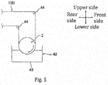
- the method for supplying a volatile liquid to a plurality of carbon nanotube single yarns 1 is not particularly limited and may be, for example, a method that includes spraying a volatile liquid to a plurality of carbon nanotube single yarns 1 (see Figs. 2 and 3A ) or a method that includes immersing a plurality of carbon nanotube single yarns 1 in a volatile liquid, etc. (see Fig. 6 )
- the method that includes spraying a volatile liquid to a plurality of carbon nanotube single yarns 1 is preferable.
- a restricting board 19 which is an example of the restricting member is preferably located such that it prevents the volatile liquid from being sprayed to the plurality of carbon nanotube single yarns 1 which are not located on the resin film 16.
- the plurality of carbon nanotube single yarns 1 are moved in the circumferential direction of the roller 2 by the friction against the resin film 16.
- the volatile liquid may be continuously supplied (preferably sprayed) to the plurality of carbon nanotube single yarns 1.
- the volatile liquid is uniformly attached to the plurality of carbon nanotube single yarns 1 (carbon nanotube sheet 6).
- the plurality of carbon nanotube single yarns 1 are drawn and separated from the resin film 16 of the roller 2.
- the manufacturing method of a carbon-nanotube twisted yarn 4 may be continuously carried out, for example, by a spinning apparatus 20, as shown in Fig. 2 .
- the spinning apparatus 20 comprises a supplying part 21, a spraying part 22, and a spinning part 23.
- the supplying part 21 is located at a rearward portion of the spinning apparatus 20 and is configured to supply a plurality of carbon nanotube single yarns 1 to the spraying part 22.
- the supplying part 21 comprises a carbon-nanotube supporting body 8 and a drawing device which is not illustrated
- the carbon-nanotube supporting body 8 comprises the substrate 9 and the carbon nanotube array 10, which are described above.
- the spraying part 22 is located at a forward position relative to the supplying part 21 with an interval therebetween.
- the spraying part 22 comprises the roller 2 which is described above, the restricting board 19 which is described above, and a spraying device 24.
- the roller 2 is located at a forward position relative to the carbon-nanotube supporting body 8 with an interval therebetween.
- the restricting board 19 is located at a forward position relative to the roller 2 with an interval therebetween.
- the interval between the restricting board 19 and the roller 2 is, for example, from 0.1 mm, or preferably 1 mm, to 50 mm, or preferably 20 mm.
- the opening 19A of the restricting board 19 is opposite in the front-back direction to an area on the resin film 16 around the roller body 15 with a central angle from 5 to 150 degrees.
- the spraying device 24 is a publicly known spraying device and is located at a forward position relative to the restricting board 19 with an interval therebetween.
- the interval between the restricting board 19 and the spraying device 24 may be, for example, from 10 mm, or preferably 30 mm, to 500 mm, or preferably 300 mm.
- the spraying device 24 comprises a nozzle 24A and is configured to spray the above-described volatile liquid backwardly.
- the nozzle 24A of the spraying device 24 is opposite in the front-back direction to an area around the roller body 15 with a central angle from 5 to 150 degrees, through the opening 19A of the restricting board 19.
- the spinning part 23 is located at a rearward position relative to the roller 2 with an interval therebetween and comprises a converging portion 26 and a collecting portion 25.
- the converging portion 26 comprises a support plate 27 and a pair of shafts 28.
- the support plate 27 has a substantially rectangular board shape extending in the left-right direction in a planar view.
- the pair of shafts 28 are located with an interval therebetween and thus are separated from each other in the left-right direction.
- Each of the pair of shafts 28 has a substantially cylindrical shape extending in the upper-lower direction and is supported by the support plate 27 so as to be relatively rotatable around its axis.
- the collecting portion 25 is located at a rearward position relative to the converging portion 26 with an interval therebetween.
- the collecting portion 25 comprises a rotating portion 30, a winding shaft 29, and a rotating shaft 31.
- the rotating portion 30 substantially has a U-shape which opens forwardly.
- the winding shaft 29 is located between the right-side wall and left-side wall of the rotating portion 30.
- the winding shaft 29 has a substantially cylindrical shape extending in the left-right direction and is rotatably supported by both the right-side wall and left-side wall of the rotating portion 30.
- the rotating shaft 31 is located at a rearward position relative to the rotating portion 30.
- the rotating shaft 31 has a substantially cylindrical shape extending in the front-back direction.
- the front end of the rotating shaft 31 is fixed to the center of the back wall of the rotating portion 30 in the left-right direction.
- the rotating portion 30 may rotate around the rotating shaft 31, namely, around an axis line along the front-back direction as its rotational center.
- the plurality of carbon nanotube single yarns 1 (carbon nanotube sheet 6) are drawn around the circumferential direction of the roller body 15 for a substantially half turn from the upper end to the lower end of the roller 2 such that the plurality of carbon nanotube single yarns 1 are located on the resin film 16. Then, the plurality of carbon nanotube single yarns 1 are drawn from the roller 2 to the back side and are caused to pass between the pair of shafts 28.
- the plurality of carbon nanotube single yarns 1 are bundled into a linear shape (yarn shape). Then the back end of the plurality of bundled carbon nanotube single yarns 1 are fixed to the winding shaft 29 of the collecting portion 25.
- roller 2 is rotated clockwise when it is seen from the left side, and the winding shaft 29 is rotated counterclockwise when it is seen from the left side, and the rotating portion 30 is rotated counterclockwise when it is seen from the front side.
- the plurality of carbon nanotube single yarns 1 move in the circumferential direction of the roller body 15 by the friction against the resin film 16 along with the rotation of the roller 2. Also, the plurality of carbon nanotube single yarns 1 are continuously drawn from the carbon nanotube array 10.
- the moving speed of the plurality of carbon nanotube single yarns 1 by the rotation of the roller 2 may be, for example, from 0.1 m/min, or preferably 5 m/min, to 100 m/min, or preferably 10 m/min.
- the spraying device 24 sprays the above-described volatile liquid through the opening 19A of the restricting board 19 to the plurality of carbon nanotube single yarns 1 which move in the circumferential direction of the roller body 15. Thereby, the volatile liquid is adhered to the plurality of carbon nanotube single yarns 1.
- the restricting board 19 prevents the liquid from adhering to the plurality of carbon nanotube single yarns 1 which are located in an upstream position or a downstream position relative to the roller 2 in the moving direction of the plurality of carbon nanotube single yarns 1 (more specifically, a region located upstream relative to an upstream end X of the plurality of carbon nanotube single yarns 1 which are located on the resin film 16 and a region located downstream relative to a downstream end Y of the plurality of carbon nanotube single yarns 1 which are located on the resin film 16 in the moving direction of the plurality of carbon nanotube single yarns 1).
- the plurality of carbon nanotube single yarns 1 to which the liquid is adhered are fed from the roller 2 to the back side by the rotation of the roller 2 and by the rotation of the winding shaft 29 such that the plurality of carbon nanotube single yarns 1 are separated from the resin film 16 of the roller 2.
- the plurality of carbon nanotube single yarns 1 are bundled by the converging portion 26 when they are caused to pass between the pair of shafts 28. Then the plurality of carbon nanotube single yarns 1 are rotated clockwise by the rotation of the rotating shaft 31 when they are seen from the front side and are thereby twisted together. At the same time, the plurality of carbon nanotube single yarns 1 are caused to move to the back side by the rotation of the winding shaft 29 and are rolled up around the winding shaft 29.
- the rotating speed (peripheral velocity) of the rotating portion 30 may be, for example, from 1,000 rpm, or preferably 2,000 rpm, to 5,000 rpm, or preferably 4,000 rpm.
- the carbon-nanotube twisted yarn 4 is manufactured by the spinning apparatus 20.
- a volatile liquid is supplied to the plurality of carbon nanotube single yarns 1 which are located on the resin film 16.
- the carbon nanotube single yarn 1 may be prevented from moving in the left-right direction by the friction between the resin film 16 and the carbon nanotube single yarn 1.
- the disarrangement of the orientations of the plurality of carbon nanotube single yarns 1 which are arranged in parallel may be suppressed.
- each of the carbon nanotube single yarns 1 the plurality of carbon nanotubes 3 aggregate to each other due to the evaporation of the volatile liquid , and thus the density of each of the carbon nanotube single yarns 1 is improved
- the plurality of carbon nanotube single yarns 1 may be densified at one time.
- the plurality of carbon nanotube yarns 1 which have been densified may be separated from the resin film 16 because the roller 2 is provided with the resin film 16.
- the plurality of carbon nanotube yarns 1 may be smoothly processed, and thus the manufacturing efficiency of the carbon nanotube twisted yarn 4 may be improved
- a liquid is sprayed to the plurality of carbon nanotube single yarns 1 which are located on the resin film 16.
- the amount of the liquid supplied to the plurality of carbon nanotube single yarns 1 may be adjusted more readily than in a case where a liquid is supplied to a plurality of carbon nanotube single yarns 1 by immersing them in the liquid.
- the orientation of the plurality of carbon nanotube single yarns 1 may be ensured
- the restricting board 19 prevents a liquid from being sprayed to the plurality of carbon nanotube single yarns 1 which are not located on the resin film 16.
- the disarrangement of the orientations of the plurality of carbon nanotube single yarns 1 may be reliably suppressed
- the restricting board 19 allows the liquid to be sprayed over an area around the roller body 15 with a central angle ⁇ , for example, from 5 to 150 degrees, however, in contrast, prevents a liquid to be sprayed to the other region.
- the volatile liquid may be uniformly sprayed to the plurality of carbon nanotube single yarns 1 which are located on the resin film 16, and thus the amount of the adhering liquid may be uniformed As a result, the density of the plurality of carbon nanotube single yarns 1 may be uniformed
- the fine particles 35 may be attached to the plurality of carbon nanotube single yarns 1 because the fine particles 35 are dispersed in the liquid As a result, the fine particles 35 may be uniformly supported by the carbon-nanotube twisted yarn 4 which is made from the plurality of carbon nanotube single yarns 1. Thereby, in addition to improving the specific surface area, the properties of the fine particles 35 (for example, improved electric conductivity, etc.) may reliably be provided to the carbon nanotube twisted yarn 4.
- the plurality of carbon nanotubes 3 are continuously connected along the extension direction of the yarn comprising the carbon nanotubes 3.
- the plurality of carbon nanotubes 3 are oriented along the extension direction of the carbon nanotube single yarn 1.
- the orientations of the carbon nanotubes 3 may be reliably ensured in the carbon nanotube single yarn 1, and thus the orientations of the carbon nanotubes 3 may be reliably ensured in the carbon-nanotube twisted yarn 4.
- the plurality of carbon nanotube single yarns 1 may be smoothly processed, and thus carbon-nanotube twisted yarn 4 may be manufactured, by a simple method in which a plurality of carbon nanotube single yarns 1 are drawn from a roller 2 and then are twisted together.
- productivity of the carbon-nanotube twisted yarn 4 may be improved.
- a plurality of carbon nanotube single yarns 1 are processed into a carbon-nanotube twisted yarn 4.
- a plurality of carbon nanotube single yarns 1 are processed into a carbon-nanotube stacked sheet 5 which is an example of the carbon nanotube collected product.
- the plurality of carbon nanotube single yarns 1 are wound around the circumferential surface of the roller 2 for a plurality of turns.
- the front end of the plurality of carbon nanotube single yarns 1 which are drawn from the carbon nanotube array 10 is fixed to the resin film 16 of the roller 2. Then a liquid is supplied to the plurality of carbon nanotube single yarns 1 while the roller 2 is rotated as in the first embodiment.
- the plurality of carbon nanotube single yarns 1 are wound around the circumferential surface of the roller 2 after a volatile liquid is sprayed to them.
- the plurality of carbon nanotube single yarns 1 which are being wound are located on the plurality of carbon nanotube single yarns 1 which have already been wound around the roller 2 such that they are exposed on the surface.
- a volatile liquid is sprayed on them.
- the plurality of external carbon nanotube single yarns 1 which are exposed on the surface are prevented from moving in the left-right direction by the friction against the plurality of internal carbon nanotube single yarns 1.
- the plurality of carbon nanotube single yarns 1 to which a liquid has been supplied are wound around the circumferential surface of the roller 2 for a plurality of turns.
- a plurality of layers of the carbon nanotube sheet 6 to which a liquid has been supplied are stacked along the radial direction of the roller 2.
- the density of each of the carbon nanotube single yarns 1 is improved, and at the same time, the plurality of wound carbon nanotube single yarns 1 (stacked carbon-nanotube sheets 6) aggregate to each other along the radial direction of the roller body 15.
- the plurality of carbon nanotube single yarns 1 which are wound around the roller 2 are cut with a cutting blade (for example, a razor, a cutter edge, etc.) in the left-right direction to separate them from the roller 2.
- a cutting blade for example, a razor, a cutter edge, etc.
- the carbon-nanotube stacked sheet 5 comprises a plurality of carbon-nanotube sheets 6 which are stacked in the thickness direction.
- the number of the stacked layers of the carbon nanotube sheets 6 may be, for example, from 5, or preferably 10, to 1,000, or preferably 500.
- the carbon-nanotube stacked sheet 5 may have a thickness of, for example, from 0.01 ⁇ m, or preferably 5 ⁇ m, to 500 ⁇ m, or preferably 200 ⁇ m.
- Such a carbon-nanotube stacked sheet 5 may be continuously manufactured by an apparatus 41 for manufacturing a stacked sheet, as shown in Fig. 4A .
- the apparatus 41 for manufacturing a stacked sheet is the same as the spinning apparatus 20 except that the apparatus 41 does not comprise a spinning part 23.
- the disarrangement of the orientations of the plurality of carbon nanotube single yarns 1 may be suppressed, and at the same time, the density of the plurality of carbon nanotube single yarns 1 which are wound around the roller 2 for a plurality of turns may be improved
- a carbon-nanotube stacked sheet 5 may be manufactured by cutting the plurality of rollers 2 which are wound around the roller 2 for a plurality of turns along the axial direction to separate them from the roller 2.
- the plurality of carbon nanotube single yarns 1 may be smoothly processed and a carbon-nanotube stacked sheet 5 may be manufactured, by a simple method in which a plurality of carbon nanotube single yarns 1 are wound around a roller 2 for a plurality of turns and then are cut.
- productivity of the carbon-nanotube stacked sheet 5 may be improved
- the second embodiment may also achieve the same functions and effects as those achieved by the above-described first embodiment.
- the carbon-nanotube stacked sheet 5 is suitably used, for example, as an electrode.
- fine particles having catalyst activity for example, metal fine particles, such as platinum, rhodium, and palladium
- a volatile solvent for example, a volatile solvent
- a volatile liquid is supplied to the plurality of carbon nanotube single yarn 1 on the resin film 16 by spraying it.
- the method for supplying a volatile liquid is not limited to this.
- a volatile liquid may also be supplied to the plurality of carbon nanotube single yarns 1 on the resin film 16 by immersing them in the volatile liquid.
- the spinning apparatus 20 comprises an immersing part 42 instead of the spraying part 22.
- the immersing part 42 comprises an immersing bath 43 and a plurality of shafts 44.
- the immersing bath 43 substantially has a box shape which opens upwardly.
- the volatile liquid as described above is stored in the immersing bath 43.
- the roller 2 is located such that the lower end of the roller 2 is immersed in the liquid in the immersing bath 43.
- the plurality of shafts 44 are appropriately located at a predetermined position such that the plurality of carbon nanotube single yarns 1 (carbon nanotube sheet 6) move to the roller 2 and then are fed from the roller 2.
- the liquid may be excessively supplied to the plurality of carbon nanotube single yarns 1.
- the plurality of carbon nanotube single yarns 1 which are arranged in parallel may move due to the surface tension, etc., of the liquid and be adhered to adjacent carbon nanotube single yarns 1.
- the first and second embodiments are more preferable than this variation.
- the restricting board 19 is located between the roller 2 and the spraying device 24.
- the position of the restricting board 19 is not particularly limited as long as the restricting board 19 may prevent a liquid from being sprayed to the plurality of carbon nanotube single yarns 1 which are not located on the resin film 16.
- the opening 19A of the restricting board 19 may be formed larger than that in the first embodiment such that the roller 2 may be located in the opening 19A.
- the upper edge of the opening 19A faces the upstream end X of the plurality of carbon nanotube single yarns 1 which are located on the resin film 16 such that there is a small interval between the opening 19A and the upstream end X.
- the lower edge of the opening 19A faces the downstream end Y of the plurality of carbon nanotube single yarns 1 which are located on the resin film 16 such that there is a small interval between the opening 19A and the downstream end Y.
- Such a variation may also achieve the same functions and effects as those achieved by the above-described first embodiment.
- the plurality of carbon nanotube single yarns 1 to which a volatile liquid has been supplied may be processed after they are dried
- the spinning apparatus 20 comprises a drying device 40.
- the drying device 40 is located between the roller 2 and the converging portion 26.
- the drying device 40 is a publicly known drier and is configured such that the plurality of carbon nanotube single yarns 1 may pass through it.
- the plurality of carbon nanotube single yarns 1 to which a volatile liquid is adhered are heated to a temperature, for example, from 80 °C to 120 °C and thereby dried when they pass through the drying device 40.
- the entirety of the roller 2 around which a plurality of carbon nanotube single yarns 1 are wound is heated to dry the plurality of carbon nanotube single yarns 1, although this is not illustrated.
- the plurality of carbon nanotube single yarns 1 are preferably heated under a reduced pressure.
- the volatile liquid is reliably evaporated and the density of each of the carbon nanotube single yarns 1 may be reliably improved
- the plurality of carbon nanotube single yarns 1 are processed into a carbon-nanotube twisted yarn 4.
- the product is not limited to this.
- the plurality of carbon nanotube single yarns 1 may be processed into a carbon nanotube untwisted yarn (an example of the carbon nanotube collected product).
- the plurality of carbon nanotube single yarns 1 are caused to pass through a die having holes according to the method disclosed in Japanese Patent Application Publication No. 2014-169521 ,etc.
- the plurality of carbon nanotube single yarns 1 are drawn at one time from the carbon nanotube array 10.
- the carbon nanotube single yarn 1 may also be drawn one by one for a plurality of times from the carbon nanotube array 10.
- the first embodiment is preferable because the plurality of carbon nanotube single yarns 1 which were drawn one by one are required to be arranged in parallel in this case.
- the roller 2 comprises the roller body 15 which is made of a metal and the resin film 16 which is made of a resin.
- the roller 2 is not limited to this.
- the roller 2 may be configured such that the roller body 15 and the resin film 16 are integrally formed of a resin.
- a blending ratio (content percentage), a physical property value, and a parameter may be replaced with the upper limits (values defined by the term “to” or “to less than”) or lower limits (values defined by the term “from” or “from greater than”) of the corresponding blending ratios (content percentages), physical property values, and parameters as described above in
- a silicon dioxide film was stacked on a substrate made of stainless steel. Then iron was evaporated as a catalyst layer on the silicon dioxide film.
- the substrate was heated to a predetermined temperature.
- a source gas acetylene gas
- acetylene gas was supplied to the catalyst layer.
- a carbon nanotube array having a substantially rectangular shape in a planar view was formed
- a plurality of carbon nanotubes extended substantially in parallel to each other and were oriented such that they were orthogonal (perpendicular) to the substrate.
- the carbon nanotubes had an average outer diameter of about 12 nm.
- the carbon nanotubes had an average length of about 200 ⁇ m.
- the plurality of carbon nanotubes 3 in the carbon nanotube array had a bulk density of about 40mg/cm 3 .
- the plurality of carbon nanotubes located at the front end portion were collectively held by a drawing device over the full width and were pulled to the front side.
- a plurality of carbon nanotube single yarns were drawn from the carbon nanotube array on the carbon-nanotube supporting body.
- the drawing speed of the carbon nanotube single yarn was 0.18 m/minutes or lower.
- the average diameter of the carbon nanotube single yarn was about 60 nm to 80 nm.
- the outer diameter of the roller body included in the spinning apparatus was 5 cm.
- the resin film was a polytetrafluoroethylene film.
- a carbon-nanotube twisted yarn was prepared in the same manner as in Example 1 except that ethanol was supplied to the plurality of carbon nanotube single yarns by immersing them in ethanoL
- a plurality of carbon nanotube single yarns were prepared in the same manner as in Example 1. Subsequently, by the apparatus for manufacturing a stacked sheet shown in Figs. 4A and 4B , ethanol (a volatile liquid) was sprayed to the plurality of carbon nanotube single yarns, and the plurality of carbon nanotube single yarns were wound around the circumferential surface of the roller for a plurality of turns.
- ethanol a volatile liquid
- the carbon-nanotube stacked sheet had a thickness of 10-20 ⁇ m.
- a carbon-nanotube stacked sheet was prepared in the same manner as in Example 3 except that carbon fine particles were dispersed in ethanol
- the carbon fine particles had a primary average particle size of 0.5 ⁇ m.
- the concentration of the dispersed carbon fine particles was 0.05 mass %.
- Example 1 the plurality of carbon nanotube single yarns were visually inspected shortly after ethanol was supplied.
- Example 1 the plurality of carbon nanotube single yarns were oriented in parallel without attaching to each other.
- Example 2 some carbon nanotube single yarns among the plurality of carbon nanotube single yarns which were arranged in parallel were attached to adjacent carbon nanotube single yarns with each other.
- Electric capacity and electric resistance of the carbon-nanotube stacked sheets in Examples 3 and 4 were evaluated as an electrode of an electric double layered capacitor.
- the electric double layered capacitor was a two-electrode cell, and the electrolyte solution was a propylene carbonate solution containing 1.6 mol/L of triethyl methyl ammonium tetrafluoroborate (TEMA-BF 4 /PC).
- the electric capacity and electric resistance were measured with an electrochemistry measurement system (1280B from Solartron Corporation). The results are shown in Table 1. Table 1 no. Electric capacity [F/g] Electric resistance [ ⁇ cm 2 ] Example 1 12 5 Example 2 19 6
- the scanning electron microscope (SEM) photograph of the carbon-nanotube stacked sheet of Example 3 is shown in Fig. 7A .
- the SEM photograph of the carbon-nanotube stacked sheet of Example 4 is shown in Fig. 7B .
- the method for manufacturing a carbon nanotube collected product of the present invention may be used conveniently to manufacture a carbon nanotube collected product used for various industrial products.
- the method may be used to manufacture a carbon-nanotube twisted yarn and a carbon-nanotube stacked sheet, etc.
Landscapes
- Chemical & Material Sciences (AREA)
- Engineering & Computer Science (AREA)
- Nanotechnology (AREA)
- Materials Engineering (AREA)
- Organic Chemistry (AREA)
- Textile Engineering (AREA)
- Inorganic Chemistry (AREA)
- Mechanical Engineering (AREA)
- General Chemical & Material Sciences (AREA)
- Chemical Kinetics & Catalysis (AREA)
- Carbon And Carbon Compounds (AREA)
- Yarns And Mechanical Finishing Of Yarns Or Ropes (AREA)
- Electric Double-Layer Capacitors Or The Like (AREA)
Applications Claiming Priority (2)
| Application Number | Priority Date | Filing Date | Title |
|---|---|---|---|
| JP2015072499A JP6462458B2 (ja) | 2015-03-31 | 2015-03-31 | カーボンナノチューブ集合体の製造方法 |
| PCT/JP2016/059029 WO2016158575A1 (fr) | 2015-03-31 | 2016-03-22 | Procédé pour fabriquer un agrégat de nanotubes de carbone |
Publications (2)
| Publication Number | Publication Date |
|---|---|
| EP3279375A1 true EP3279375A1 (fr) | 2018-02-07 |
| EP3279375A4 EP3279375A4 (fr) | 2018-11-07 |
Family
ID=57004988
Family Applications (1)
| Application Number | Title | Priority Date | Filing Date |
|---|---|---|---|
| EP16772456.6A Withdrawn EP3279375A4 (fr) | 2015-03-31 | 2016-03-22 | Procédé pour fabriquer un agrégat de nanotubes de carbone |
Country Status (7)
| Country | Link |
|---|---|
| US (1) | US20180073166A1 (fr) |
| EP (1) | EP3279375A4 (fr) |
| JP (1) | JP6462458B2 (fr) |
| KR (1) | KR101974903B1 (fr) |
| CN (1) | CN107429438B (fr) |
| TW (1) | TWI689464B (fr) |
| WO (1) | WO2016158575A1 (fr) |
Cited By (2)
| Publication number | Priority date | Publication date | Assignee | Title |
|---|---|---|---|---|
| WO2019216067A1 (fr) * | 2018-05-10 | 2019-11-14 | Murata Machinery, Ltd. | Appareil de préparation d'extrémité de sortie de substrat de nanotubes de carbone, système de filage, méthode de préparation d'extrémité de sortie de substrat de nanotubes de carbone et méthode de filage |
| WO2020111520A1 (fr) | 2018-11-30 | 2020-06-04 | Awexomeray | Procédé de préparation d'une feuille de nanotubes de carbone comprenant un fil aligné uniaxialement et feuille de nanotubes de carbone ainsi préparée |
Families Citing this family (13)
| Publication number | Priority date | Publication date | Assignee | Title |
|---|---|---|---|---|
| JP6699517B2 (ja) * | 2016-11-11 | 2020-05-27 | Jnc株式会社 | 紡績源部材、ウェブ状構造体、紡績源部材の製造方法およびウェブ状構造体の製造方法 |
| WO2018118682A1 (fr) * | 2016-12-19 | 2018-06-28 | Lintec Of America, Inc. | Système de filage de fil de nanofibres |
| JP6829609B2 (ja) * | 2017-01-16 | 2021-02-10 | 日立造船株式会社 | カーボンナノチューブウェブの引出方法 |
| JP7011704B2 (ja) * | 2017-08-08 | 2022-02-10 | リンテック・オヴ・アメリカ,インコーポレイテッド | エッジ面を使用したナノファイバシートの密度の変更 |
| JP7133827B2 (ja) * | 2017-09-29 | 2022-09-09 | 国立研究開発法人産業技術総合研究所 | カーボンナノチューブ撚糸体、キャパシター及びフィルター |
| KR102445848B1 (ko) * | 2018-03-26 | 2022-09-21 | 쑤저우 저나노 카본 컴퍼니 리미티드 | 수집장치 및 제조시스템 |
| CN108609434B (zh) * | 2018-03-26 | 2020-11-03 | 苏州捷迪纳米科技有限公司 | 收集装置及制备系统 |
| JP7280564B2 (ja) * | 2018-08-31 | 2023-05-24 | 株式会社アイシン | カーボンナノチューブ電極及びこれを用いた蓄電デバイス |
| KR101956153B1 (ko) | 2018-10-04 | 2019-06-24 | 어썸레이 주식회사 | 탄소나노튜브를 포함하는 얀의 제조방법 및 이로부터 제조된 얀 |
| KR101992745B1 (ko) | 2019-01-24 | 2019-06-26 | 어썸레이 주식회사 | 구조적 안정성이 우수하고 전자 방출 효율이 향상된 이미터 및 이를 포함하는 x-선 튜브 |
| KR102099410B1 (ko) | 2019-04-04 | 2020-04-09 | 어썸레이 주식회사 | 세라믹계 소재로 이루어진 집속전극을 포함하는 x-선 발생장치 |
| KR102099411B1 (ko) | 2019-07-26 | 2020-04-09 | 어썸레이 주식회사 | 구조적 안정성이 우수한 전계 방출 장치 및 이를 포함하는 x-선 튜브 |
| JPWO2021044963A1 (fr) * | 2019-09-03 | 2021-03-11 |
Family Cites Families (14)
| Publication number | Priority date | Publication date | Assignee | Title |
|---|---|---|---|---|
| US7399443B2 (en) * | 2004-02-27 | 2008-07-15 | Lucent Technologies Inc. | Carbon particle fiber assembly technique |
| US8926933B2 (en) | 2004-11-09 | 2015-01-06 | The Board Of Regents Of The University Of Texas System | Fabrication of twisted and non-twisted nanofiber yarns |
| EP2607518B1 (fr) * | 2005-11-04 | 2017-06-21 | Nanocomp Technologies, Inc. | Antennes nanostructurées |
| CN100450922C (zh) * | 2006-11-10 | 2009-01-14 | 清华大学 | 一种超长定向的碳纳米管丝/薄膜及其制备方法 |
| WO2009045487A1 (fr) * | 2007-10-02 | 2009-04-09 | Los Alamos National Security, Llc | Fibre de nanotube de carbone filée à partir de ruban mouillé |
| JP5229732B2 (ja) * | 2008-11-11 | 2013-07-03 | 地方独立行政法人大阪府立産業技術総合研究所 | 微細炭素繊維撚糸の製造装置及び製造方法 |
| CN101905878A (zh) * | 2009-06-04 | 2010-12-08 | 清华大学 | 碳纳米管线状结构及其制备方法 |
| CN101964229B (zh) * | 2009-07-21 | 2012-05-30 | 清华大学 | 碳纳米管绞线及其制备方法 |
| CN101967699B (zh) * | 2010-10-13 | 2012-08-08 | 中国科学院苏州纳米技术与纳米仿生研究所 | 高性能碳纳米管纤维的制备方法 |
| CN102953171A (zh) * | 2011-08-30 | 2013-03-06 | 苏州捷迪纳米科技有限公司 | 碳纳米管纺纱机及采用该碳纳米管纺纱机制备碳纳米管纱线的方法 |
| CN103159204B (zh) * | 2011-12-09 | 2015-03-25 | 北京富纳特创新科技有限公司 | 碳纳米管膜的制备方法 |
| CN103964411B (zh) * | 2013-01-30 | 2016-01-13 | 北京富纳特创新科技有限公司 | 处理碳纳米管膜的方法 |
| EP3026157B1 (fr) | 2013-07-22 | 2020-03-11 | Murata Machinery, Ltd. | Dispositif de fabrication de fil |
| WO2015011771A1 (fr) * | 2013-07-22 | 2015-01-29 | 村田機械株式会社 | Dispositif de fabrication de fil |
-
2015
- 2015-03-31 JP JP2015072499A patent/JP6462458B2/ja active Active
-
2016
- 2016-03-22 US US15/560,364 patent/US20180073166A1/en not_active Abandoned
- 2016-03-22 EP EP16772456.6A patent/EP3279375A4/fr not_active Withdrawn
- 2016-03-22 KR KR1020177027437A patent/KR101974903B1/ko active IP Right Grant
- 2016-03-22 WO PCT/JP2016/059029 patent/WO2016158575A1/fr active Application Filing
- 2016-03-22 CN CN201680019702.1A patent/CN107429438B/zh not_active Expired - Fee Related
- 2016-03-30 TW TW105109941A patent/TWI689464B/zh not_active IP Right Cessation
Cited By (4)
| Publication number | Priority date | Publication date | Assignee | Title |
|---|---|---|---|---|
| WO2019216067A1 (fr) * | 2018-05-10 | 2019-11-14 | Murata Machinery, Ltd. | Appareil de préparation d'extrémité de sortie de substrat de nanotubes de carbone, système de filage, méthode de préparation d'extrémité de sortie de substrat de nanotubes de carbone et méthode de filage |
| WO2020111520A1 (fr) | 2018-11-30 | 2020-06-04 | Awexomeray | Procédé de préparation d'une feuille de nanotubes de carbone comprenant un fil aligné uniaxialement et feuille de nanotubes de carbone ainsi préparée |
| EP3887307A4 (fr) * | 2018-11-30 | 2022-08-31 | Awexome Ray, Inc. | Procédé de préparation d'une feuille de nanotubes de carbone comprenant un fil aligné uniaxialement et feuille de nanotubes de carbone ainsi préparée |
| US11453591B2 (en) | 2018-11-30 | 2022-09-27 | Awexome Ray, Inc. | Process for preparing a carbon nanotube sheet comprising a uniaxially aligned yarn and carbon nanotube sheet prepared thereby |
Also Published As
| Publication number | Publication date |
|---|---|
| KR101974903B1 (ko) | 2019-05-03 |
| JP6462458B2 (ja) | 2019-01-30 |
| EP3279375A4 (fr) | 2018-11-07 |
| TWI689464B (zh) | 2020-04-01 |
| CN107429438A (zh) | 2017-12-01 |
| KR20170121266A (ko) | 2017-11-01 |
| TW201639781A (zh) | 2016-11-16 |
| US20180073166A1 (en) | 2018-03-15 |
| CN107429438B (zh) | 2020-03-24 |
| JP2016191173A (ja) | 2016-11-10 |
| WO2016158575A1 (fr) | 2016-10-06 |
Similar Documents
| Publication | Publication Date | Title |
|---|---|---|
| EP3279375A1 (fr) | Procédé pour fabriquer un agrégat de nanotubes de carbone | |
| EP3412808A1 (fr) | Procédé de production d'un fil torsadé de nanotubes de carbone, et fil torsadé de nanotubes de carbone | |
| EP3263753A1 (fr) | Procédé de fabrication de fibre de nanotube de carbone, dispositif de fabrication de fibre de nanotube de carbone, et fibre de nanotube de carbone | |
| US11208740B2 (en) | Method for producing carbon nanotube yarn | |
| US20180179064A1 (en) | Method for producing carbon nanotube web, method for producing carbon nanotube collected product, and apparatus for producing carbon nanotube web | |
| CN104176722B (zh) | 一种高取向高强度的阵列牵伸碳纳米管薄膜及其制备方法 | |
| CN113165878A (zh) | 用于制备包含单轴对准的纱线的碳纳米管片的方法和由此制备的碳纳米管片 | |
| US10899619B2 (en) | Method for producing carbon nanotube web, method for producing carbon nanotube collected product, and apparatus for producing carbon nanotube web | |
| EP4033018A1 (fr) | Procédé de fabrication de fil torsadé de nanotubes de carbone, et dispositif de fabrication de fil torsadé de nanotubes de carbone | |
| JP2016160539A (ja) | カーボンナノチューブ繊維の製造方法、カーボンナノチューブ繊維の製造装置およびカーボンナノチューブ繊維 |
Legal Events
| Date | Code | Title | Description |
|---|---|---|---|
| PUAI | Public reference made under article 153(3) epc to a published international application that has entered the european phase |
Free format text: ORIGINAL CODE: 0009012 |
|
| 17P | Request for examination filed |
Effective date: 20170928 |
|
| AK | Designated contracting states |
Kind code of ref document: A1 Designated state(s): AL AT BE BG CH CY CZ DE DK EE ES FI FR GB GR HR HU IE IS IT LI LT LU LV MC MK MT NL NO PL PT RO RS SE SI SK SM TR |
|
| AX | Request for extension of the european patent |
Extension state: BA ME |
|
| DAV | Request for validation of the european patent (deleted) | ||
| DAX | Request for extension of the european patent (deleted) | ||
| A4 | Supplementary search report drawn up and despatched |
Effective date: 20181008 |
|
| RIC1 | Information provided on ipc code assigned before grant |
Ipc: D02G 3/16 20060101ALI20181001BHEP Ipc: C01B 32/164 20170101AFI20181001BHEP |
|
| RIC1 | Information provided on ipc code assigned before grant |
Ipc: D02G 3/16 20060101ALI20181001BHEP Ipc: C01B 32/164 20170101AFI20181001BHEP |
|
| STAA | Information on the status of an ep patent application or granted ep patent |
Free format text: STATUS: THE APPLICATION HAS BEEN WITHDRAWN |
|
| 18W | Application withdrawn |
Effective date: 20200103 |