EP3278836A1 - Elektromedizinisches implantat mit einer elektrischen durchführung - Google Patents
Elektromedizinisches implantat mit einer elektrischen durchführung Download PDFInfo
- Publication number
- EP3278836A1 EP3278836A1 EP17183988.9A EP17183988A EP3278836A1 EP 3278836 A1 EP3278836 A1 EP 3278836A1 EP 17183988 A EP17183988 A EP 17183988A EP 3278836 A1 EP3278836 A1 EP 3278836A1
- Authority
- EP
- European Patent Office
- Prior art keywords
- housing
- electrical
- housing segment
- segment
- conductor
- Prior art date
- Legal status (The legal status is an assumption and is not a legal conclusion. Google has not performed a legal analysis and makes no representation as to the accuracy of the status listed.)
- Granted
Links
Images



Classifications
-
- A—HUMAN NECESSITIES
- A61—MEDICAL OR VETERINARY SCIENCE; HYGIENE
- A61N—ELECTROTHERAPY; MAGNETOTHERAPY; RADIATION THERAPY; ULTRASOUND THERAPY
- A61N1/00—Electrotherapy; Circuits therefor
- A61N1/18—Applying electric currents by contact electrodes
- A61N1/32—Applying electric currents by contact electrodes alternating or intermittent currents
- A61N1/36—Applying electric currents by contact electrodes alternating or intermittent currents for stimulation
- A61N1/372—Arrangements in connection with the implantation of stimulators
- A61N1/375—Constructional arrangements, e.g. casings
- A61N1/3752—Details of casing-lead connections
- A61N1/3754—Feedthroughs
-
- A—HUMAN NECESSITIES
- A61—MEDICAL OR VETERINARY SCIENCE; HYGIENE
- A61B—DIAGNOSIS; SURGERY; IDENTIFICATION
- A61B5/00—Measuring for diagnostic purposes; Identification of persons
- A61B5/07—Endoradiosondes
- A61B5/076—Permanent implantation
-
- A—HUMAN NECESSITIES
- A61—MEDICAL OR VETERINARY SCIENCE; HYGIENE
- A61B—DIAGNOSIS; SURGERY; IDENTIFICATION
- A61B5/00—Measuring for diagnostic purposes; Identification of persons
- A61B5/24—Detecting, measuring or recording bioelectric or biomagnetic signals of the body or parts thereof
- A61B5/25—Bioelectric electrodes therefor
- A61B5/279—Bioelectric electrodes therefor specially adapted for particular uses
- A61B5/28—Bioelectric electrodes therefor specially adapted for particular uses for electrocardiography [ECG]
- A61B5/283—Invasive
- A61B5/29—Invasive for permanent or long-term implantation
-
- A—HUMAN NECESSITIES
- A61—MEDICAL OR VETERINARY SCIENCE; HYGIENE
- A61B—DIAGNOSIS; SURGERY; IDENTIFICATION
- A61B5/00—Measuring for diagnostic purposes; Identification of persons
- A61B5/68—Arrangements of detecting, measuring or recording means, e.g. sensors, in relation to patient
- A61B5/6846—Arrangements of detecting, measuring or recording means, e.g. sensors, in relation to patient specially adapted to be brought in contact with an internal body part, i.e. invasive
- A61B5/6847—Arrangements of detecting, measuring or recording means, e.g. sensors, in relation to patient specially adapted to be brought in contact with an internal body part, i.e. invasive mounted on an invasive device
- A61B5/686—Permanently implanted devices, e.g. pacemakers, other stimulators, biochips
-
- A—HUMAN NECESSITIES
- A61—MEDICAL OR VETERINARY SCIENCE; HYGIENE
- A61N—ELECTROTHERAPY; MAGNETOTHERAPY; RADIATION THERAPY; ULTRASOUND THERAPY
- A61N1/00—Electrotherapy; Circuits therefor
- A61N1/18—Applying electric currents by contact electrodes
- A61N1/32—Applying electric currents by contact electrodes alternating or intermittent currents
- A61N1/36—Applying electric currents by contact electrodes alternating or intermittent currents for stimulation
- A61N1/3605—Implantable neurostimulators for stimulating central or peripheral nerve system
-
- A—HUMAN NECESSITIES
- A61—MEDICAL OR VETERINARY SCIENCE; HYGIENE
- A61N—ELECTROTHERAPY; MAGNETOTHERAPY; RADIATION THERAPY; ULTRASOUND THERAPY
- A61N1/00—Electrotherapy; Circuits therefor
- A61N1/18—Applying electric currents by contact electrodes
- A61N1/32—Applying electric currents by contact electrodes alternating or intermittent currents
- A61N1/36—Applying electric currents by contact electrodes alternating or intermittent currents for stimulation
- A61N1/3605—Implantable neurostimulators for stimulating central or peripheral nerve system
- A61N1/36053—Implantable neurostimulators for stimulating central or peripheral nerve system adapted for vagal stimulation
-
- A—HUMAN NECESSITIES
- A61—MEDICAL OR VETERINARY SCIENCE; HYGIENE
- A61N—ELECTROTHERAPY; MAGNETOTHERAPY; RADIATION THERAPY; ULTRASOUND THERAPY
- A61N1/00—Electrotherapy; Circuits therefor
- A61N1/18—Applying electric currents by contact electrodes
- A61N1/32—Applying electric currents by contact electrodes alternating or intermittent currents
- A61N1/36—Applying electric currents by contact electrodes alternating or intermittent currents for stimulation
- A61N1/3605—Implantable neurostimulators for stimulating central or peripheral nerve system
- A61N1/3606—Implantable neurostimulators for stimulating central or peripheral nerve system adapted for a particular treatment
- A61N1/36062—Spinal stimulation
-
- A—HUMAN NECESSITIES
- A61—MEDICAL OR VETERINARY SCIENCE; HYGIENE
- A61N—ELECTROTHERAPY; MAGNETOTHERAPY; RADIATION THERAPY; ULTRASOUND THERAPY
- A61N1/00—Electrotherapy; Circuits therefor
- A61N1/18—Applying electric currents by contact electrodes
- A61N1/32—Applying electric currents by contact electrodes alternating or intermittent currents
- A61N1/36—Applying electric currents by contact electrodes alternating or intermittent currents for stimulation
- A61N1/362—Heart stimulators
-
- A—HUMAN NECESSITIES
- A61—MEDICAL OR VETERINARY SCIENCE; HYGIENE
- A61N—ELECTROTHERAPY; MAGNETOTHERAPY; RADIATION THERAPY; ULTRASOUND THERAPY
- A61N1/00—Electrotherapy; Circuits therefor
- A61N1/18—Applying electric currents by contact electrodes
- A61N1/32—Applying electric currents by contact electrodes alternating or intermittent currents
- A61N1/36—Applying electric currents by contact electrodes alternating or intermittent currents for stimulation
- A61N1/372—Arrangements in connection with the implantation of stimulators
- A61N1/37211—Means for communicating with stimulators
- A61N1/37217—Means for communicating with stimulators characterised by the communication link, e.g. acoustic or tactile
-
- A—HUMAN NECESSITIES
- A61—MEDICAL OR VETERINARY SCIENCE; HYGIENE
- A61N—ELECTROTHERAPY; MAGNETOTHERAPY; RADIATION THERAPY; ULTRASOUND THERAPY
- A61N1/00—Electrotherapy; Circuits therefor
- A61N1/18—Applying electric currents by contact electrodes
- A61N1/32—Applying electric currents by contact electrodes alternating or intermittent currents
- A61N1/36—Applying electric currents by contact electrodes alternating or intermittent currents for stimulation
- A61N1/372—Arrangements in connection with the implantation of stimulators
- A61N1/37211—Means for communicating with stimulators
- A61N1/37217—Means for communicating with stimulators characterised by the communication link, e.g. acoustic or tactile
- A61N1/37223—Circuits for electromagnetic coupling
- A61N1/37229—Shape or location of the implanted or external antenna
-
- A—HUMAN NECESSITIES
- A61—MEDICAL OR VETERINARY SCIENCE; HYGIENE
- A61N—ELECTROTHERAPY; MAGNETOTHERAPY; RADIATION THERAPY; ULTRASOUND THERAPY
- A61N1/00—Electrotherapy; Circuits therefor
- A61N1/18—Applying electric currents by contact electrodes
- A61N1/32—Applying electric currents by contact electrodes alternating or intermittent currents
- A61N1/36—Applying electric currents by contact electrodes alternating or intermittent currents for stimulation
- A61N1/372—Arrangements in connection with the implantation of stimulators
- A61N1/375—Constructional arrangements, e.g. casings
-
- A—HUMAN NECESSITIES
- A61—MEDICAL OR VETERINARY SCIENCE; HYGIENE
- A61N—ELECTROTHERAPY; MAGNETOTHERAPY; RADIATION THERAPY; ULTRASOUND THERAPY
- A61N1/00—Electrotherapy; Circuits therefor
- A61N1/18—Applying electric currents by contact electrodes
- A61N1/32—Applying electric currents by contact electrodes alternating or intermittent currents
- A61N1/36—Applying electric currents by contact electrodes alternating or intermittent currents for stimulation
- A61N1/372—Arrangements in connection with the implantation of stimulators
- A61N1/375—Constructional arrangements, e.g. casings
- A61N1/37512—Pacemakers
-
- A—HUMAN NECESSITIES
- A61—MEDICAL OR VETERINARY SCIENCE; HYGIENE
- A61N—ELECTROTHERAPY; MAGNETOTHERAPY; RADIATION THERAPY; ULTRASOUND THERAPY
- A61N1/00—Electrotherapy; Circuits therefor
- A61N1/18—Applying electric currents by contact electrodes
- A61N1/32—Applying electric currents by contact electrodes alternating or intermittent currents
- A61N1/36—Applying electric currents by contact electrodes alternating or intermittent currents for stimulation
- A61N1/372—Arrangements in connection with the implantation of stimulators
- A61N1/375—Constructional arrangements, e.g. casings
- A61N1/37514—Brain implants
-
- A—HUMAN NECESSITIES
- A61—MEDICAL OR VETERINARY SCIENCE; HYGIENE
- A61N—ELECTROTHERAPY; MAGNETOTHERAPY; RADIATION THERAPY; ULTRASOUND THERAPY
- A61N1/00—Electrotherapy; Circuits therefor
- A61N1/18—Applying electric currents by contact electrodes
- A61N1/32—Applying electric currents by contact electrodes alternating or intermittent currents
- A61N1/36—Applying electric currents by contact electrodes alternating or intermittent currents for stimulation
- A61N1/372—Arrangements in connection with the implantation of stimulators
- A61N1/375—Constructional arrangements, e.g. casings
- A61N1/3756—Casings with electrodes thereon, e.g. leadless stimulators
-
- A—HUMAN NECESSITIES
- A61—MEDICAL OR VETERINARY SCIENCE; HYGIENE
- A61N—ELECTROTHERAPY; MAGNETOTHERAPY; RADIATION THERAPY; ULTRASOUND THERAPY
- A61N1/00—Electrotherapy; Circuits therefor
- A61N1/18—Applying electric currents by contact electrodes
- A61N1/32—Applying electric currents by contact electrodes alternating or intermittent currents
- A61N1/38—Applying electric currents by contact electrodes alternating or intermittent currents for producing shock effects
- A61N1/39—Heart defibrillators
- A61N1/3956—Implantable devices for applying electric shocks to the heart, e.g. for cardioversion
- A61N1/3962—Implantable devices for applying electric shocks to the heart, e.g. for cardioversion in combination with another heart therapy
- A61N1/39622—Pacing therapy
-
- A—HUMAN NECESSITIES
- A61—MEDICAL OR VETERINARY SCIENCE; HYGIENE
- A61N—ELECTROTHERAPY; MAGNETOTHERAPY; RADIATION THERAPY; ULTRASOUND THERAPY
- A61N1/00—Electrotherapy; Circuits therefor
- A61N1/18—Applying electric currents by contact electrodes
- A61N1/32—Applying electric currents by contact electrodes alternating or intermittent currents
- A61N1/36—Applying electric currents by contact electrodes alternating or intermittent currents for stimulation
- A61N1/372—Arrangements in connection with the implantation of stimulators
- A61N1/37205—Microstimulators, e.g. implantable through a cannula
Definitions
- the invention is directed to electromedical implants for the measurement and delivery of electrical pulses or z.
- Electro-medical implants for the measurement of electrical potentials as well as for the delivery of electrical pulses have been used for decades in the human and animal body to measure electrical potentials that are caused by nerve activity. Also known for a long time are implants that are used for electrical stimulation of nerve structures. A typical indication for the need of such an implant is a disturbed and / or not appropriate endogenous (intrinsic) nerve activity or conduction. There are various measuring and / or stimulation devices that differ in shape and design depending on the technical characteristics and the area of application of the nervous system.
- Implants consist for. B. from a device unit and various electrode conductors.
- the device unit has the device electronics, which include, for example, electrical circuits for measurements and analysis of the electrical potentials and for controlling the electrical stimulation.
- the instrument cluster typically includes an energy source for the implant, such as a battery, as well as electrical connections for the electrode leads.
- Known electrode conductors for such applications have an elongate conductor body, one or more electrodes at the distal end of the conductor as well an electrical contact at the proximal end of the conductor, with which they can be connected to the electrical connections of the device unit.
- the device assembly is inserted subcutaneously at a suitable location under the patient's skin, while the electrode leads are implanted in locations suitable for nerve tissue measurements and stimulation, and connected to the device aggregate.
- a similar structure to the described spinal cord stimulation system has known systems for the stimulation of the heart.
- standard cardiac pacing systems, implantable cardiac defibrillators, or cardiac rhythm resynchronization systems (CRT systems) typically also consist of a device assembly and electrode leads.
- electrode leads are advanced via the superior vena cava into the right atrium and right ventricle of the heart and anchored at the desired implantation site.
- Electrode conductors for the measurement and stimulation of the left half of the heart are typically placed in a branch of the coronary sinus.
- the device aggregate of such a cardiac stimulator is embedded subcutaneously in the clavicle region of the patient and connected to the electrode conductor.
- Cardiac pacing systems are known in the art that do not have electrode leads as described above. Such pacemaker systems are also referred to as 'leadless' systems, more precisely, 'leadless pacemaker'. Such systems have a device assembly in which the electrodes are located on the housing for measurement and stimulation. The device unit is implanted via a catheter system directly in the atrium or in the ventricle of the heart and fixed there.
- implantable pure monitoring devices for the heart are known. These are placed subcutaneously and do not have electrode leads implanted intracardially. Such devices have measuring electrodes on the device housing, are recorded via the electrical potentials, for example, to filter out heart signals.
- known structures of said leadless systems and pure monitors are such that they have a device housing housing equipment electronics and power supplies. Within the housing device electronics and power supply via an electrical feedthrough are electrically connected. Furthermore, such a typical structure provides that the device electronics is connected via a further electrical feedthrough to a measuring electrode. In this case, the housing is electrically coupled to the second electrode pole for the electrical measurement and / or electrical stimulation and thus serves as a counterpole to the measuring electrode.
- an implantable medical device wherein the medical device has at least two electrodes which are coupled to the device housing.
- implantable monitoring devices and in general for implantable electromedical devices and in particular for the latter without electrode leads, miniaturization of the device housing or device housing is advantageous.
- Another object of the present invention is to provide a novel implantable electromedical device having a novel device structure that is simple and inexpensive to manufacture.
- an electromedical implant which comprises a housing, wherein the housing has three housing segments A, B and C ,.
- Housing segment A is connected to housing segment B
- housing segment B is connected to housing segment C such that housing segment B is disposed between housing segments A and C.
- Housing segment A and housing segment C consist at least partially of electrically conductive material.
- the electromedical implant according to the invention comprises an electronic module, which is arranged within the housing segment A and comprises an electrical circuit for receiving and further processing electrical signals, as well as at least a first and a second electrical conductor for measuring electrical potentials and / or output of electrical Pulses, each conductor has a conductor start and a conductor end and each conductor start is connected to the electrical circuit.
- the electromedical implant according to the invention comprises a battery module, which is arranged in the interior of the housing segment C, or wherein the battery module has a battery housing, which is formed by housing segment C.
- the electromedical implant according to the invention has an electrical feedthrough, wherein the electrical feedthrough at least partially consists of electrically insulating material and housing segment B is formed by parts of the feedthrough.
- the electronics module and the battery module are electrically connected via the feedthrough, housing segment A and housing segment C being electrically insulated from each other by the feedthrough.
- the conductor end of the first electrical conductor is electrically connected to the part of the housing segment C made of electrically conductive material via the leadthrough, and the conductor end of the second electrical conductor is electrically connected to the part of the housing segment A made of electrically conductive material.
- the electromedical implant according to the invention has a single electrical feedthrough.
- housing segment is understood to mean that it is a section of the housing.
- the housing segments A and / or C may consist of a single material, such as metal or other skilled in the art appearing as an electrically conductive material, which preferably has biocompatibility.
- a segment comprises different materials, such as consists of a composite material or composite material.
- suitable materials include biocompatible and conductive metals and metal alloys such as titanium, titanium alloys, stainless steels (including 316L), other alloys such as e.g. MP35N, conductive and biocompatible plastics and plastic or ceramic composites.
- Housing segment B is preferably at least partially made of electrically insulating material. Suitable for this purpose would be, for example, glass, ceramics, plastics or composite materials from those mentioned.
- housing segment B consists of electrically insulating material, wherein the housing is designed so that the housing segment A and housing segment C are electrically insulated from each other by housing segment B.
- housing segments A and C are designed as housing shells.
- a "housing shell” is to be understood as meaning a geometric hollow body with at least one opening, which can be advantageously used as part of a housing for an implant according to the present invention.
- Forms of the housing shell can be considered to be advantageous, which ensure high patient comfort after implantation, as well as forms associated with a low risk of infection after implantation and / or those which are easy to implant and remain firmly in place after implantation at their implantation site. without them slipping or twisting. It makes sense if the shape of the housing shell has a small total outer surface relative to the inner volume. Also, shapes are available with few corners and edges, or with rounded corners and edges.
- a housing shell can be designed as a hollow cuboid with an open sidewall or paraboloid.
- the electronic module of the electromedical implant according to the invention is arranged in the interior of the housing segment A and comprises an electrical circuit.
- This includes, for example, electrical circuits for recording and processing of electrical potentials as well as units for storage, signal processing and signal analysis.
- the circuit may include components for the delivery of electrical pulses as well as for the coordination of these pulses. Also conceivable would be circuit components for wireless data transmission (telemetry) of measured and stored data to external systems or an external patient device.
- the electronic module comprises at least a first and second conductor. The conductors are connected with their respective conductor start with the electrical circuit.
- an "electrical conductor” is generally understood to mean an electrical conductor connection with which electronic elements can be contacted.
- Such a conductor connection can be listed, for example, as a conductor wire with conductor start and conductor end, or designed as a conductor on a board with electrical contacting possibility at the beginning and end of the conductor, or as a conductive part of an electrical feedthrough, or a combination of the above and others, for the person skilled in expedient possibilities.
- the battery module is arranged inside the housing segment C.
- no direct electrical connection it is to be understood in the sense of the embodiment of the invention that the battery module and housing segment C are to be electrically insulated such that no direct electrical connection is achieved an electrical conductor between battery module and housing segment C is implemented.
- housing segment C is electrically connected to the electrical circuit of the electronic module and that the electrical potential of the electrically conductive Material existing part of the housing segment C is determined by this connection.
- the electromedical implant according to the invention has an electrical feedthrough.
- an electrical feedthrough is understood to be an element for electrical conduction which is designed to transfer or couple in an electrical signal from one environment to another, wherein signal properties and quality are to be retained as well as possible. For example, this may be the coupling of a signal into a device housing, or from one housing segment to another housing segment.
- the electrical feedthrough consists of a feedthrough body in which electrical conductor elements are integrated or pass through the electrical conductor elements. The conductor elements each lead from a first outer surface of the feedthrough body through the feedthrough body to a second outer surface of the feedthrough body.
- the first and the second outer surface may in this case represent the same outer surface or different outer surfaces of the bushing body.
- the conductor elements have at their ends via electrical contacts, which protrude from the corresponding outer surface and can be coupled via this the electrical signal in the implementation. In one embodiment, said electrical contacts will be connected by soldering to the feedthrough body.
- the lead-through body is at least partially made of an electrically insulating material. In one embodiment, the entire feedthrough body is made of such a material. In any case, however, according to the invention, the electrical feedthrough or the leadthrough body is designed to electrically insulate housing segments A and C from each other so that there is no direct current path from housing segment A to the housing segment C via the feedthrough.
- the housing segment B is formed by parts of the passage, for example by a number of outer surfaces of the bushing body.
- the entirety of the housing segment B can be formed by parts of the bushing or of the bushing body.
- the electronics module is disposed inside the housing segment A, while the battery module is disposed inside the housing segment C.
- the electronic module and the battery module are preferably electrical connected to each other via / through the implementation. This can be ensured by additional electrical conductors which connect the electronics module to electrical contacts on the side of the feedthrough facing the electronics module, and additional electrical conductors which connect the battery module to electrical contacts on the side of the feedthrough facing the battery module.
- said first electrical conductor whose conductor start is connected to the electrical circuit is connected to the conductor end with a part of the housing segment C, which consists of electrically conductive material, wherein the first conductor leads through the passage.
- the current path of the first conductor thus leads from the electrical circuit through the passage to the housing segment C, which consists of electrically conductive material.
- Said second electrical conductor whose conductor start is also connected to the electrical circuit is connected to the conductor end with the part of the housing segment A consisting of electrically conductive material.
- housing segment A and / or C can also consist entirely of electrically conductive material.
- housing segments A and C are optionally contacted by means of further electrical conductors which lead through the bushing. It is conceivable in one embodiment that housing segment A or C (or the electrically conductive part of the respective segment) in each case lie firmly on the plus or minus pole of the battery of the battery module. It is also conceivable that the electrical potential of the electrically conductive parts of the housing segments A and C are designed changeable (in English 'ftoating').
- the housing of the implant has an elongated shape, wherein housing segments A and C are designed as housing shells.
- the housing shells are firmly connected at the open ends to the bushing. This is preferably a soldered or welded connection.
- the electro-medical implant according to the invention is a cardiac implant in the form of a sensor, monitoring device, pacemaker device, pacemaker device with integrated defibrillator function or pacemaker device without intracardiac electrodes. Also conceivable would be all implantable electromedical devices that have two electrodes and for which a miniaturization of the implant is advantageous.
- the electromedical implant is a pure cardiac monitoring implant or a miniaturized cardiac pacing implant without an intracardiac lead or leadless pacemaker implant.
- the electromedical implant according to the invention is a neurostimulation implant in the form of a spinal cord stimulation device, vagus nerve stimulation device, or brain stimulation device. Also conceivable would be the execution of the electromedical implant as a muscle stimulation device.
- housing segment A and / or housing segment C of the proposed electromedical implant on a coating of electrically insulating material wherein housing segment A and / or housing segment C has at least one area without a coating of electrically insulating. In this case, the area preferably does not adjoin housing segment B.
- housing segment A and / or housing segment C have at least in part a coating which forms the housing segment improved electrical coupling, such. As a fractal coating with surface-enlarging properties, and / or the coating has bioactive properties.
- Advantageous materials for such a coating are, for example, silicones, parylene, diamond-like carbon (DLC), paints, powder coatings or nanocoatings, or a mixture or combination of said materials.
- silicones parylene
- DLC diamond-like carbon
- Such a coating may serve to determine the electrical path from housing segment A to C across the tissue (this path represents the electrical measurement and / or stimulation vector).
- this path represents the electrical measurement and / or stimulation vector.
- the points at which the current should emerge on or out of the housing segment are not coated.
- the current path for the measurement and / or stimulation vector is selected so that it is sufficiently long. If the electromedical implant according to the invention has an elongate shape, then the named exit points are preferably designed so that they are located at the ends of the longitudinal axis of the implant.
- the electrical feedthrough, or the feedthrough body of the electrical feedthrough consists of a ceramic material and / or a composite material.
- exemplary suitable materials are Al2O3, ZrO2, Ti2O.
- materials for the stated purpose are materials of multilayer technology, for example, ceramic materials of multi-layer technology (High Temperature Co-fired Ceramics HTCC, Low Temperature Co-fired Ceramics LTCC).
- the electromedical implant has at least one active or passive component, the component being integrated in the bushing and / or being connected to the bushing.
- Exemplary passive or active electronic components are passive or active filters, as well as passive or active assemblies for radio frequency (RF) applications such as signal transmission with external devices or signal transmission within an association of active implants and / or passive or active assemblies for the management of the battery.
- RF radio frequency
- the electromedical implant according to the invention has an antenna, which is integrated in the bushing and / or connected to the leadthrough.
- the antenna is for sending and receiving data to / from an external system or device for the purpose of telemetry.
- an external system or device for the purpose of telemetry.
- the electromedical implant according to the invention has an antenna which is formed by the two housing segments A and C of the electromedical implant (and the electric dipole) which are electrically insulated from one another.
- the housing segment A is connected to housing segment B and / or housing segment B is connected to housing segment C by means of low temperature soldering, laser soldering, cold welding, friction welding, fusion welding, gluing or ultrasonic bonding.
- the electrical feedthrough has a construction of a plurality of layers, wherein the layers consist alternately of electrically insulating and electrically conductive material.
- the layers consist alternately of electrically insulating and electrically conductive material.
- a "housing shell” is to be understood as meaning a geometric hollow body with at least one opening, which can be advantageously used as part of a housing for an implant according to the present invention.
- Forms of the housing shell can be considered to be advantageous, which ensure a high patient comfort after the implantation and forms that are associated with a low infection risk after implantation and / or those that are easy to implant and remain firmly attached to their implantation site after implantation without slipping or twisting. It makes sense if the shape of the housing shell has a small total outer surface relative to the inner volume. Also, shapes are available with few corners and edges, or with rounded corners and edges.
- a housing shell can be designed as a hollow cuboid with an open sidewall or paraboloid.
- the housing shells A and / or C can consist of a single material, such as, for example, of metal or another electrically conductive material which appears to be suitable for a person skilled in the art and which preferably has biocompatibility. Furthermore, it is also conceivable that a housing shell comprises different materials, such as consists of a composite material. Possible materials suitable materials include metal-plastic composites, metal-ceramic composites, metal-glass composites.
- the electrical feedthrough has a feedthrough body, which preferably consists at least partially of electrically insulating material. Suitable for this purpose would be, for example, glass, ceramics, plastics or composite materials from those mentioned.
- the electronic module in the sense of the method according to the invention is arranged in the interior of the housing shell A and comprises an electrical circuit.
- This includes, for example, electrical circuits for recording and processing of electrical potentials as well as units for storage, signal processing and signal analysis.
- the circuit may include components for the delivery of electrical pulses as well as for the coordination of these pulses. Also conceivable would be circuit components for wireless data transmission (telemetry) of measured and stored data to external systems or an external patient device.
- the electronic module comprises at least a first and second conductor. The conductors are connected with their respective conductor start with the electrical circuit.
- the term "establishing an electrical connection” is to be understood in general as the implementation of an electrical conductor connection, so that electronic elements are contacted.
- a conductor connection can be listed, for example, as a conductor wire with conductor start and conductor end, or as a conductor on a circuit board with electrical contacting possibility be designed at the beginning and end of the trace, or as a conductive part of an electrical feedthrough, or a combination of the above and other, suitable for the expert possibilities.
- the battery module is arranged in the interior of the housing shell C.
- the first and the second outer surface may in this case represent the same outer surface or different outer surfaces of the bushing body.
- the conductor elements have at their ends via electrical contacts, which protrude from the corresponding outer surface and can be coupled via this the electrical signal in the implementation. In one embodiment, said electrical contacts will be connected by soldering to the feedthrough body.
- the lead-through body is at least partially made of an electrically insulating material. In one embodiment, the entire feedthrough body is made of such a material. In any case, in the sense of the method according to the invention, the electrical leadthrough or the leadthrough body is designed to electrically insulate housing shells A and C from each other so that there is no direct current path from housing shell A to the housing shell C.
- the electronics module is inside the Housing shell A arranged while the battery module is disposed inside the housing shell C.
- the electronic module and the battery module are preferably electrically connected to each other via / through the implementation. This can be ensured by additional electrical conductors which connect the electronics module to electrical contacts on the side of the feedthrough facing the electronics module, and additional electrical conductors which connect the battery module to electrical contacts on the side of the feedthrough facing the battery module.
- the bushing is arranged between the electronics module and the battery module.
- the electronic module is electrically connected to the battery module via the electrical leads in the implementation, further electrical connections are made between the electrical circuit and the existing of electrically conductive material part of the housing shell A and between the electrical circuit and the existing part of electrically conductive material the housing shell C on the implementation.
- Housing shell A and C are each connected to the electronics module or to the battery module side of the implementation.
- bonding is preferably understood to mean a joining together of the corresponding components, so that a stable, solid material composite is formed, for example by soldering, welding or gluing. According to the proposed method housing shell A and C are thus electrically insulated from each other by the implementation.
- a current path is generated between the housing shell A and C and the electronics module or the battery module, which leads from the electrical circuit of the electronic module to the electrically conductive part of the housing shell A, from there to the electrically conductive part of the housing shell C, then by carrying back to the electrical circuit. Consequently, the two electrode poles required for the measurement or output of electrical pulses are formed by the electrically conductive part of housing shell A and housing shell C.
- housing shell A and / or C can also consist entirely of electrically conductive material.
- the method comprises contacting the housing shells A and C by means of further electrical conductors, which lead through the implementation. It is conceivable in one embodiment that housing shells A and C (or the electrically conductive part of the respective housing shell) each lie firmly on the plus or minus pole of the battery of the battery module. It is also conceivable that the electrical potential of the electrically conductive parts of the housing shells A and C are changeable (in English 'floating') are designed.
- the electromedical implant is designed as a cardiac implant in the form of a sensor, monitoring device, pacemaker device, pacemaker device with integrated defibrillator function or pacemaker device without intracardiac electrodes.
- the inventive method for producing an electromedical implant comprises at least the further step of coating the housing shell A and / or the housing shell C with electrically insulating material, wherein a portion of the housing shell A and / or housing shell C is not coated, wherein the Area is not adjacent to the implementation.
- Advantageous materials for such a coating are, for example, silicones, parylene, diamond-like carbon (DLC), paints, powder coatings or nanocoatings, or a mixture or combination of said materials.
- silicones parylene
- DLC diamond-like carbon
- Such a coating can serve to determine the electrical path from housing shell A to C across the tissue (this path represents the electrical measurement and / or stimulation vector).
- this path represents the electrical measurement and / or stimulation vector.
- the points at which the current should emerge on or out of the housing shell not coated.
- the current path for the measurement and / or stimulation vector is selected so that it is sufficiently long. If the electromedical implant according to the invention has an elongate shape, then the named exit points are preferably designed so that they are located at the ends of the longitudinal axis of the implant.
- the attachment of the housing shell A takes place and / or housing shell C by a low-temperature soldering, laser soldering, cold welding, friction welding, fusion welding, gluing or ultrasonic welding.
- the method according to the invention for producing an electromedical implant comprises at least the further step of integrating at least one passive or active component and / or one antenna in the feedthrough.
- the antenna is for sending and receiving data to / from an external system or device for the purpose of telemetry.
- the electrical leadthrough has a construction of a plurality of layers, wherein the layers consist alternately of electrically insulating and electrically conductive material.
- the layers consist alternately of electrically insulating and electrically conductive material.
- housing shell A and / or housing shell C is constructed of two assembled half-shells.
- Such a modular construction of the housing shells allows a simplified manufacture of the housing shells.
- the half-shells can be joined together to form a housing shell by welding.
- Fig. 1a and 1b show an exemplary implantable device 10 for measuring electrical potentials from the prior art. It will be in Fig. 1a the outer structure of such an implantable device 10 illustrated with a housing consisting of battery case 11, a battery cover with first passage 12 and electronics housing 13. Furthermore, the implantable device 10 has a second passage 14 and a measuring electrode 15. In Fig. 1b dashed the internal structure of the implantable device 10 is shown, consisting of battery module 16, electronic module 17, electrical connections 18a and 18b, which electrically connect battery module 16 and electronic module 17 on the implementation in the battery cover 12, and electrical connection 19, which the electronic module with the measuring electrode 15 connects.
- the counter electrode to the measuring electrode 15 can be formed by the housing.
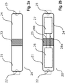
- Fig. 2a and 2b show an embodiment of an electromedical implant 20 in the context of the invention.
- Illustrated Fig. 2a the outer structure of the electromedical implant 20, consisting of a first housing segment 21 with a part 22 consisting of electrically conductive material, an electrical feedthrough 23, a second housing segment 24 with a part 25 consisting of electrically conductive material.
- Fig. 2b schematically shows the internal structure (dashed lines) of the embodiment in Fig. 2a , comprising a battery module 26, an electronic module 27 and two electrical connections 28a and 28b, electrically connect the battery module 26 and electronics module 27 via the feedthrough 23. Further provided for the functionality of the invention electrical connections and interconnections are in Fig. 2b not shown for reasons of clarity.
- Fig. 3 shows a preferred embodiment of the connection between passage 23 with the adjacent housing segments 21 and 24 in the sectional view.
- first metallic terminal contacts can be soldered on the bushing 23, in order then to connect the housing segments at the corresponding interfaces 30a and 30b to the bushing, for example by means of laser welding.
- Fig. 4 shows an advantageous embodiment of the electrical connection and interconnection for the electromedical implant according to the invention.
- the electromedical implant 20 has, according to the embodiment in Fig. 2a and 2b , a first housing segment 21, an electrical feedthrough 23 and a second housing segment 24.
- battery module 26 Inside the electromedical implant 20 are battery module 26, an electronic module 27 and two electrical connections 28a and 28b, the battery module 26 and electronics module 27 via the feedthrough 23 electrically connect.
- the electronic module has an electrical circuit 40, which may include, for example, electrical circuits for receiving and processing electrical potentials as well as units for storage, signal processing and signal analysis. Furthermore, the circuit may include components for the delivery of electrical pulses as well as for the coordination of these pulses.
- the electronic module 27 comprises at least a first conductor 42 and a second conductor 43.
- Conductor 42 is electrically connected to the housing segment 21 or to the part of the housing segment 21 consisting of electrically conductive material, leads through the electrical feedthrough 23 to the electronic module 27
- Lead conductor 42 in the first input of an operational amplifier 41.
- Conductor 43 is electrically connected to housing segment 24 or to the part of housing segment 24 made of electrically conductive material, and leads to the electronic module 27.
- conductor 41 can lead into a second input of the operational amplifier 41.
- the recorded electrical potentials via conductors 42 and 43 are amplified by amplifier 41 and forwarded to the electrical circuit 40, where they are further processed.
- Fig. 5 schematically shows exemplary embodiments 50a, 50b and 50c for the electrical implementation of the electromedical implant according to the invention in the sectional view.
- Embodiment 50d shows the electrical feed through of the electromedical implant in plan view.
- Implementation variant 50a consists of a feedthrough body 52 and two electrical contacts 51, which lead through the feedthrough body and at the ends of electrical contacts can be attached (for example by soldering).
- Implementation variant 50b includes additional electrical paths 53, which pass through the feedthrough body 52. These additional conductors can be used for further modifications and adaptations of the electrical potentials of the housing segments, for example in order to make the electrical potentials dynamically variable (in English 'floating').
- Implementation variant 50 c comprises further components 54 which can be integrated on or in the feedthrough body 52 and / or can be connected to the feedthrough body 52.
- Exemplary devices are electronic passive or active devices such as [so], or antenna shapes for the purpose of telemetry.
- Embodiment 50d shows a variant of the bushing in which an antenna 55 is integrated in the leadthrough, for example antenna 55 can be incorporated into the leadthrough body 52 or antenna 55 is connected to the bushing, for example applied to the surface of the leadthrough body 52.
- Fig. 6 schematically shows an exemplary embodiment 60 for the electrical implementation of the electromedical implant with multilayer structure according to the invention in the sectional view.
- the bushing 60 consists of a plurality of alternating layers of electrically insulating material 61 and electrically conductive material 62. Electrical conductors 63 pass through the layers and can be contacted so that further electrical poles can form on the layers of electrically conductive material 62. About these poles further electrical potentials can be measured or electrical Pulses are delivered.
- implementation 60 may also comprise further electronic components 64, which are integrated on and / or in the layers and / or connected to the layers. Exemplary devices are electronic passive or active devices or antenna shapes for the purpose of telemetry.
- Fig. 7 shows an embodiment of the electromedical implant according to the invention, in which the housing segments are designed as housing shells, wherein a housing shell is composed of two half-shells.
- 70 and 71 show side views of the embodiment of the electromedical implant, wherein the housing segment accommodating the module 71 is assembled from two half shells 72 and 73.
- the module 71 may represent the battery module or the electronic module according to the invention.
- Area 73 shows in detail the location at which half-shells 72 and 73 adjoin lead-through 74.
- Housing segment 75 is an embodiment of the housing segment according to the invention as a housing shell and may also consist of two half shells. It would also be conceivable to construct a housing segment according to the invention from more than two components.
- the joining of the half-shells 72 and 73, or the joining of the half-shells 72 and 73 to the bushing 74 can be implemented by joining methods such as low-temperature soldering, laser soldering, cold welding, friction welding, fusion welding, gluing or ultrasonic welding.
Landscapes
- Health & Medical Sciences (AREA)
- Life Sciences & Earth Sciences (AREA)
- Engineering & Computer Science (AREA)
- Biomedical Technology (AREA)
- Animal Behavior & Ethology (AREA)
- General Health & Medical Sciences (AREA)
- Public Health (AREA)
- Veterinary Medicine (AREA)
- Nuclear Medicine, Radiotherapy & Molecular Imaging (AREA)
- Radiology & Medical Imaging (AREA)
- Physics & Mathematics (AREA)
- Heart & Thoracic Surgery (AREA)
- Cardiology (AREA)
- Neurology (AREA)
- Neurosurgery (AREA)
- Biophysics (AREA)
- Pathology (AREA)
- Medical Informatics (AREA)
- Molecular Biology (AREA)
- Surgery (AREA)
- Acoustics & Sound (AREA)
- Electromagnetism (AREA)
- Orthopedic Medicine & Surgery (AREA)
- Electrotherapy Devices (AREA)
Abstract
Description
- Die Erfindung ist gerichtet an elektromedizinische Implantate zur Messung sowie zur Abgabe von elektrischen Pulsen oder auch z. B. als implantierbare Zentraleinheit zur drahtlosen Signalübertragung zwischen mehreren Implantaten und an den optimierten Aufbau derartiger Implantate.
- Elektromedizinische Implantate zur Messung von elektrischen Potentialen sowie zur Abgabe von elektrischen Pulsen werden seit Jahrzehnten im menschlichen und tierischen Körper zur Messung von elektrischen Potentialen eingesetzt, die durch Nervenaktivität hervorgerufen werden. Auch seit langem bekannt sind Implantate, die zur elektrischen Stimulation von Nervenstrukturen eingesetzt werden. Typische Indikation für den Bedarf eines solchen Implantats ist eine gestörte und/oder nicht bedarfsgerechte körpereigene (intrinsische) Nervenaktivität bzw. Erregungsleitung. Dabei existieren verschiedene Mess- und/oder Stimulationsgeräte, die sich je nach technischen Eigenschaften sowie nach Einsatzbereich des Nervensystems in Form und Ausführung unterscheiden.
- Systeme für die Rückenmarksstimulation werden beispielsweise eingesetzt, wenn Nervenstrukturen für die Funktionalität der Extremitäten geschädigt wurden, dann in der Regel zur Schmerztherapie oder zur Unterstützung der Rehabilitation. Derartige Implantate bestehen z. B. aus einem Geräteaggregat und verschiedenen Elektrodenleitern. Das Geräteaggregat verfügt über die Gerätelektronik, welche beispielsweise elektrische Schaltungen für Messungen und Analyse der elektrischen Potentiale sowie für Steuerung der elektrischen Stimulation beinhalten. Auch beinhaltet das Geräteaggregat typischerweise eine Energiequelle für das Implantat, wie eine Batterie, sowie elektrische Anschlüsse für die Elektrodenleiter. Bekannte Elektrodenleiter für derartige Einsatzzwecke besitzen einen länglichen Leiterkörper, eine oder mehrere Elektroden am distalen Ende des Leiters sowie einen elektrischen Kontakt am proximalen Ende des Leiters, mit dem sie an die elektrischen Anschlüsse des Geräteaggregats angeschlossen werden können. Beim Implantationsvorgang wird das Geräteaggregat subkutan an einer geeigneten Stelle unter der Haut des Patienten eingesetzt, während die Elektrodenleiter an für Messungen und Stimulationen des Nervengewebes geeignete Orte implantiert und an das Geräteaggregat angeschlossen werden.
- Einen ähnlichen Aufbau wie das beschriebene Rückenmarksstimulationssystem besitzen bekannte Systeme für die Stimulation des Herzens. So bestehen gängige Herzschrittmachersysteme, implantierbare kardiale Defibrillatoren oder Systeme zur Resynchronisation des Herzens (Cardiac Rhythm Therapy, CRT Systeme) auch typischerweise aus Geräteaggregat und Elektrodenleiter. Für die Messung und Stimulation der rechten Herzhälfte werden Elektrodenleiter über die obere Hohlvene in den rechten Vorhof und rechten Ventrikel des Herzens vorgeschoben und am gewünschten Implantationsort verankert. Elektrodenleiter für die Messung und Stimulation der linken Herzhälfte werden typischerweise in einer Abzweigung des Koronarsinus platziert. Das Geräteaggregat eines solchen Herzstimulators wird im Schlüsselbeinbereich des Patienten subkutan eingebettet und mit dem Elektrodenleiter verbunden.
- Es sind Herzschrittmachersysteme im Stand der Technik bekannt, die nicht über oben beschriebene Elektrodenleiter verfügen. Solche Herzschrittmachersysteme werden auch als 'leadless' Systeme bezeichnet, genauer 'leadless pacemaker'. Derartige Systeme verfügen über ein Geräteaggregat, bei welchem die Elektroden zur Messung und Stimulation am Gehäuse lokalisiert sind. Das Geräteaggregat wird über ein Kathetersystem direkt im Vorhof oder im Ventrikel des Herzens implantiert und dort fixiert.
- Weiterhin sind auch implantierbare reine Überwachungsgeräte für das Herz bekannt. Diese werden subkutan platziert und verfügen nicht über Elektrodenleiter, die intrakardial implantiert werden. Solche Geräte weisen Messelektroden am Gerätegehäuse auf, über die elektrische Potentiale aufgenommen werden, um beispielsweise Herzsignale herauszufiltern.
- Genauer gesagt sind bekannte Aufbauten von besagten 'leadless' Systemen und reinen Überwachungsgeräten dergestalt, dass sie über ein Gerätegehäuse verfügen, in welchem Geräteelektronik und Energieversorgung beherbergt sind. Innerhalb des Gehäuses sind Geräteelektronik und Energieversorgung über eine elektrische Durchführung miteinander elektrisch verbunden. Des Weiteren sieht ein solcher typischer Aufbau vor, dass die Geräteelektronik über eine weitere elektrische Durchführung mit einer Messelektrode verbunden ist. Dabei ist das Gehäuse elektrisch gekoppelt mit dem zweiten Elektrodenpol für die elektrische Messung und/oder elektrische Stimulation und dient somit als Gegenpol zur Messelektrode.
- Beispielsweise wird in
US 2015/0073507 A1 ein implantierbares medizinisches Gerät vorgeschlagen, wobei das medizinische Gerät über mindestens zwei Elektroden verfügt, die an das Gerätegehäuse gekoppelt sind. - Die bislang bekannten 'leadless' Systeme, implantierbare Überwachungsgeräte, sowie allgemeine implantierbare elektromedizinische Geräte und insbesondere letztere ohne Elektrodenleitungen besitzen einen relativ komplexen Geräteaufbau z.B. mit elektrischen Durchführungen und separaten Antennen.
- Für beschriebene 'leadless' Systeme, implantierbare Überwachungsgeräte, sowie allgemein für implantierbare elektromedizinische Geräte und insbesondere für letztere ohne Elektrodenleitungen ist eine Miniaturisierung des Geräteaufbaus bzw. Gerätegehäuses vorteilhaft.
- Es ist deshalb Aufgabe der vorliegenden Erfindung, ein neuartiges implantierbares elektromedizinisches Gerät bereitzustellen, das in seinen Dimensionen und im Volumen kleiner ist als bisherige bekannte implantierbare Geräte vergleichbarer Art.
- Eine weitere Aufgabe der vorliegenden Erfindung liegt darin, ein neuartiges implantierbares elektromedizinisches Gerät bereitzustellen, das einen neuartigen Geräteaufbau aufweist, welcher einfach und kostengünstig herzustellen ist.
- Die Aufgabe wird erfindungsgemäß durch die Merkmale der unabhängigen Ansprüche gelöst. Günstige Ausgestaltungen und Vorteile der Erfindung ergeben sich aus den weiteren Ansprüchen und der Beschreibung.
- Gemäß der vorliegenden Erfindung wird ein elektromedizinisches Implantat vorgeschlagen, welches ein Gehäuse umfasst, wobei das Gehäuse drei Gehäusesegmente A, B und C, aufweist. Gehäusesegment A ist mit ist mit Gehäusesegment B verbunden, und Gehäusesegment B ist mit Gehäusesegment C verbunden, sodass Gehäusesegment B zwischen den Gehäusesegmenten A und C angeordnet ist. Dabei bestehen Gehäusesegment A sowie Gehäusesegment C mindestens teilweise aus elektrisch leitendem Material. Des Weiteren umfasst das erfindungsgemäße elektromedizinische Implantat ein Elektronikmodul, das innerhalb des Gehäusesegments A angeordnet ist und eine elektrische Schaltung zur Aufnahme und Weiterverarbeitung von elektrischen Signalen umfasst, sowie mindestens einen ersten und einen zweiten elektrischen Leiter zur Messung von elektrischen Potentialen und/oder Abgabe von elektrischen Pulsen, wobei jeder Leiter jeweils einen Leiteranfang und ein Leiterende aufweist und jeder Leiteranfang mit der elektrischen Schaltung verbunden ist. Auch umfasst das erfindungsgemäße elektromedizinische Implantat ein Batteriemodul, das im Inneren des Gehäusesegments C angeordnet ist, oder wobei das Batteriemodul ein Batteriegehäuse aufweist, welches durch Gehäusesegment C gebildet wird. Dabei weist das erfindungsgemäße elektromedizinische Implantat eine elektrische Durchführung auf, wobei die elektrische Durchführung mindestens teilweise aus elektrisch isolierendem Material besteht und Gehäusesegment B durch Teile der Durchführung gebildet wird. Gemäß der Erfindung sind das Elektronikmodul und das Batteriemodul über die Durchführung elektrisch verbunden, wobei Gehäusesegment A und Gehäusesegment C durch die Durchführung voneinander elektrisch isoliert sind. Des Weiteren ist das Leiterende des ersten elektrischen Leiters mit dem aus elektrisch leitendem Material bestehenden Teil des Gehäusesegments C über die Durchführung elektrisch verbunden, und das Leiterende des zweiten elektrischen Leiters ist mit dem aus elektrisch leitendem Material bestehenden Teil des Gehäusesegments A elektrisch verbunden.
- In einer bevorzugten Ausführungsform weist das erfindungsgemäße elektromedizinische Implantat eine einzige elektrische Durchführung auf.
- In diesem Zusammenhang soll unter einem "Gehäusesegment" verstanden werden, dass es sich um einen Abschnitt des Gehäuses handelt. Dabei können die Gehäusesegmente A und/oder C kann aus einem einzigen Material bestehen, wie zum Beispiel aus Metall oder einem anderen dem Fachmann als zweckdienlich erscheinenden, elektrisch leitenden Material, welches vorzugsweise Biokompatibilität aufweist. Des Weiteren ist auch denkbar, dass ein solches Segment verschiedene Materialien umfasst, wie beispielsweise aus einem Materialverbund bzw. Verbundmaterial besteht. Mögliche geeignete Materialien sind biokompatible und leitfähige Metalle und Metalllegierungen wie Titan, Titanlegierungen, Edelstähle (u.a. 316L), andere Legierungen wie z.B. MP35N, leitfähige und biokompatible Kunststoffe und Kunststoff- bzw. Keramik-Verbundmaterialien. Gehäusesegment B besteht vorzugsweise zumindest teilweise aus elektrisch isolierendem Material. Geeignet für diesen Zweck wären beispielsweise Glas, Keramik, Kunststoffe bzw. Verbundmaterialien aus den genannten.
- In einer bevorzugten Ausführungsform des erfindungsgemäßen elektromedizinischen Implantats besteht Gehäusesegment B aus elektrisch isolierendem Material, wobei das Gehäuse so ausgelegt ist, sodass Gehäusesegment A und Gehäusesegment C durch Gehäusesegment B voneinander elektrisch isoliert sind.
- In einer bevorzugten Ausführungsform des erfindungsgemäßen elektromedizinischen Implantats sind Gehäusesegmente A und C als Gehäuseschalen ausgeführt. In diesem Zusammenhang soll unter einer "Gehäuseschale" ein geometrischer Hohlkörper mit mindestens einer Öffnung verstanden werden, welcher vorteilhaft als Teil eines Gehäuses für ein Implantat gemäß der vorliegenden Erfindung verwendet werden kann. Als vorteilhaft können Formen der Gehäuseschale angesehen werden, die nach der Implantation für einen hohen Patientenkomfort sorgen sowie Formen, die mit einem geringen Infektionsrisiko nach der Implantation einhergehen und/oder solche, die einfach zu implantieren sind und nach der Implantation fest an ihrem Implantationsort verbleiben, ohne dass sie verrutschen oder sich verdrehen. Dabei bietet es sich an, wenn die Form der Gehäuseschale eine kleine Gesamtaußenfläche relativ zum Innenvolumen aufweist. Auch sind bieten sich Formen mit wenigen Ecken und Kanten an, bzw. mit abgerundeten Ecken und Kanten. Beispielsweise kann eine Gehäuseschale als hohler Quader mit einer offenen Seitenwand oder Paraboloid ausgeführt sein.
- Das Elektronikmodul des erfindungsgemäßen elektromedizinischen Implantats ist im Inneren des Gehäusesegments A angeordnet und umfasst eine elektrische Schaltung. Diese beinhaltet beispielsweise elektrische Schaltkreise für die Aufnahme und Verarbeitung von elektrischen Potentialen sowie Einheiten zur Speicherung, Signalweiterverarbeitung und Signalanalyse. Des Weiteren kann der Schaltkreis Komponenten für die Abgabe von elektrischen Pulsen sowie zur Koordination dieser Pulse beinhalten. Ebenfalls denkbar wären Schaltkreiskomponenten für die drahtlose Datenübertragung (Telemetrie) von gemessenen und gespeicherten Daten an externe Systeme oder ein externes Patientengerät. Weiterhin umfasst das Elektronikmodul mindestens einen ersten und zweiten Leiter. Die Leiter sind mit ihrem jeweiligen Leiteranfang mit der elektrischen Schaltung verbunden.
- Im Zusammenhang der vorliegenden Erfindung soll unter einem "elektrischen Leiter" allgemein eine elektrische Leiterverbindung verstanden werden, mit der elektronische Elemente kontaktiert werden können. Eine solche Leiterverbindung kann beispielsweise als Leiterdraht mit Leiteranfang und Leiterende aufgeführt sein, oder als Leiterbahn auf einer Platine mit elektrischer Kontaktierungsmöglichkeit an Anfang und Ende der Leiterbahn, oder als leitender Teil einer elektrischen Durchführung ausgelegt sein, oder einer Kombination aus den genannten und weiteren, für den Fachmann zweckdienlichen Möglichkeiten.
- Das Batteriemodul ist im Inneren des Gehäusesegments C angeordnet. In einer bevorzugten Ausführungsform besteht keine direkte elektrische Verbindung zwischen dem Batteriemodul und Gehäusesegment C. Unter "keine direkte elektrische Verbindung" soll im Sinne der Ausführungsform der Erfindung verstanden werden, dass Batteriemodul und Gehäusesegment C derart elektrisch isoliert sein sollen, dass keine unmittelbare elektrische Verbindung über einen elektrischen Leiter zwischen Batteriemodul und Gehäusesegment C implementiert ist. Hintergrund dafür ist, dass in einer bevorzugten Ausführungsform der Erfindung Gehäusesegment C mit der elektrischen Schaltung des Elektronikmoduls elektrisch verbunden ist und dass das elektrische Potential des aus elektrisch leitendem Material bestehenden Teils des Gehäusesegments C durch diese Verbindung bestimmt wird.
- Gemäß der vorliegenden Erfindung weist das erfindungsgemäße elektromedizinische Implantat eine elektrische Durchführung auf. Im Sinne der Erfindung wird unter einer elektrischen Durchführung ein Element zur elektrischen Leitung verstanden, welches ausgelegt ist, ein elektrisches Signal von einer Umgebung in eine andere überzuführen bzw. einzukoppeln, wobei Signaleigenschaften und -Qualität so gut wie möglich erhalten bleiben sollen. Beispielsweise kann es sich dabei um die Einkopplung eines Signals in ein Gerätegehäuse, oder von einem Gehäusesegment in ein anderes Gehäusesegment handeln. Im Sinne der Erfindung besteht die elektrische Durchführung aus einem Durchführungskörper, in den elektrische Leiterelemente integriert sind bzw. durch den elektrische Leiterelemente durchführen. Dabei führen die Leiterelemente jeweils von einer ersten Außenfläche des Durchführungskörpers durch den Durchführungskörper hindurch zu einer zweiten Außenfläche des Durchführungskörpers. Die erste und die zweite Außenfläche können hierbei dieselbe Außenfläche oder unterschiedliche Außenflächen des Durchführungskörpers darstellen. Die Leiterelemente verfügen an ihren Enden über elektrische Kontakte, die an der entsprechenden Außenfläche überstehen und über diese das elektrische Signal in die Durchführung eingekoppelt werden kann. In einer Ausführungsform werden besagte elektrische Kontakte durch Anlöten am Durchführungskörper angebunden werden. Bevorzugt besteht der Durchführungskörper mindestens teilweise aus einem elektrisch isolierenden Material. In einer Ausführungsform besteht der gesamte Durchführungskörper aus einem solchen Material. Auf jeden Fall jedoch ist im Sinne der Erfindung die elektrische Durchführung bzw. der Durchführungskörper ausgelegt, Gehäusesegmente A und C elektrisch voneinander zu isolieren, sodass kein direkter Strompfad von Gehäusesegment A über die Durchführung zu Gehäusesegment C besteht. Dabei wird das Gehäusesegment B durch Teile der Durchführung gebildet, beispielsweise von einer Anzahl an Außenflächen des Durchführungskörpers. Beispielsweise kann die Gesamtheit des Gehäusesegments B durch Teile der Durchführung bzw. des Durchführungskörpers gebildet werden. Innerhalb des Gehäuses ist, wie zuvor erwähnt, das Elektronikmodul im Inneren des Gehäusesegments A angeordnet, während das Batteriemodul im Inneren des Gehäusesegments C angeordnet ist. Dabei sind das Elektronikmodul und das Batteriemodul vorzugsweise elektrisch über/durch die Durchführung miteinander verbunden. Dies kann durch zusätzliche elektrische Leiter gewährleistet werden, die das Elektronikmodul mit elektrischen Kontakten an der zum Elektronikmodul gerichteten Seite der Durchführung verbinden, sowie zusätzliche elektrische Leiter, die das Batteriemodul mit elektrischen Kontakten an der zum Batteriemodul gerichteten Seite der Durchführung verbinden.
- Weiterhin ist besagter erster elektrischer Leiter, dessen Leiteranfang mit der elektrischen Schaltung verbunden ist, mit dem Leiterende mit einem Teil des Gehäusesegments C verbunden, der aus elektrisch leitendem Material besteht, wobei der erste Leiter durch die Durchführung führt. Der Strompfad der ersten Leiters führt somit von der elektrischen Schaltung durch die Durchführung zum Gehäusesegment C, der aus elektrisch leitendem Material besteht. Besagter zweiter elektrischer Leiter, dessen Leiteranfang ebenfalls mit der elektrischen Schaltung verbunden ist, ist mit dem Leiterende mit dem aus elektrisch leitendem Material bestehenden Teil des Gehäusesegments A verbunden. Gemäß der vorliegenden Erfindung besteht zwischen Gehäusesegment A bzw. C und dem Elektronikmodul bzw. dem Batteriemodul außer den elektrischen Verbindungen über den ersten und zweiten Leiter (sowie eventuell erforderliche Massepotential-Verbindungen) keine weitere elektrische Verbindung. Auf diese Weise wird ein Strompfad erzeugt, der von der elektrischen Schaltung des Elektronikmoduls zum elektrisch leitenden Teil des Gehäusesegments A führt, von dort aus zum elektrisch leitenden Teil des Gehäusesegments C und dann über den zweiten Leiter durch die Durchführung zurück zur elektrischen Schaltung. Folglich werden die zwei für die Messung bzw. Abgabe von elektrischen Pulsen erforderlichen Elektrodenpole gebildet durch den elektrisch leitenden Teil von Gehäusesegment A und Gehäusesegment C. Wie zuvor erwähnt können dabei Gehäusesegment A und/oder C auch gänzlich aus elektrisch leitendem Material bestehen.
- In einer vorteilhaften Ausführung der vorliegenden Erfindung sind Gehäusesegmente A und C gegebenenfalls mittels weiterer elektrischer Leiter, welche durch die Durchführung führen, kontaktiert. Dabei ist in einer Ausführungsform denkbar, dass Gehäusesegment A bzw. C (oder der elektrisch leitende Teil des jeweiligen Segments) jeweils fest auf dem Plus- bzw. Minuspol der Batterie des Batteriemoduls liegen. Auch denkbar ist es, dass das elektrische Potential der elektrisch leitenden Teile der Gehäusesegmente A und C veränderlich (auf Englisch 'ftoating') gestaltet sind.
- In einer Ausführungsform des erfindungsgemäßen elektromedizinischen Implantats weist das Gehäuse des Implantats eine längliche Form auf, wobei Gehäusesegmente A und C als Gehäuseschalen ausgeführt sind. Die Gehäuseschalen sind jeweils an den offenen Enden mit der Durchführung fest verbunden. Dabei handelt es sich bevorzugt um eine Löt- oder Schweißverbindung.
- Gemäß einer Ausführungsform ist das erfindungsgemäße elektromedizinische Implantat ein kardiales Implantat in Form eines Sensors, Überwachungsgeräts, Schrittmachergeräts, Schrittmachergeräts mit integrierter Defibrillatorfunktion oder Schrittmachergeräts ohne intrakardiale Elektroden ausgeführt. Denkbar wären auch sämtliche implantierbare elektromedizinische Geräte, die über zwei Elektroden verfügen und für die eine Miniaturisierung des Implantats vorteilhaft ist. In einer bevorzugten Ausführung der Erfindung handelt es sich beim elektromedizinischen Implantat um ein reines kardiales Überwachungsimplantat (Monitoring-Implantat) oder um ein miniaturisiertes kardiales Schrittmacherimplantat ohne intrakardiale Elektrodenleiter oder 'leadless pacemaker' Implantat.
- Gemäß einer Ausführungsform ist das erfindungsgemäße elektromedizinische Implantat ein Neurostimulationsimplantat in Form eines Rückenmarkstimulationsgeräts, Vagusnerv-Stimulationsgeräts, oder Hirnstimulationsgeräts. Auch denkbar wäre die Ausführung des elektromedizinischen Implantats als Muskelstimulationgerät.
- In einer vorteilhaften Ausgestaltung der Erfindung weist das Gehäusesegment A und/oder Gehäusesegment C des vorgeschlagenen elektromedizinischen Implantats eine Beschichtung aus elektrisch isolierendem Material auf, wobei Gehäusesegment A und/oder Gehäusesegment C mindestens einen Bereich ohne Beschichtung aus elektrisch isolierendem aufweist. Vorzugsweise grenzt der Bereich dabei nicht an Gehäusesegment B. In einer Ausführung des erfindungsgemäßen elektromedizinischen Implantats weisen Gehäusesegment A und/oder Gehäusesegment C zumindest teilweise eine Beschichtung auf, die die elektrische Kopplung verbessert, wie z. B. eine fraktale Beschichtung mit oberflächenvergrößernden Eigenschaften, und/oder die Beschichtung weist bioaktive Eigenschaften auf.
- Vorteilhafte Materialien für eine derartige Beschichtung stellen beispielsweise Silikone, Parylene, Diamond-like Carbon (DLC), Lacke, Pulverbeschichtungen oder Nanobeschichtungen dar, bzw. eine Mischung oder Kombination aus genannten Materialien.
- Eine solche Beschichtung kann dazu dienen, den elektrischen Pfad von Gehäusesegment A zu C über das Gewebe (dieser Pfad stellt den elektrischen Mess- und/oder Stimulationsvektor dar) zu bestimmen. Dazu werden die Stellen, an denen der Strom ein- bzw. aus dem Gehäusesegment austreten soll, nicht beschichtet. Vorzugsweise wird der Strompfad für den Mess- und/oder Stimulationsvektor so gewählt, dass er hinreichend lang ist. Wenn das erfindungsgemäße elektromedizinische Implantat eine längliche Form aufweist, so sind die benannten Austrittsstellen vorzugsweise so ausgelegt, dass sie sich an den Enden der Längsachse des Implantats befinden.
- Gemäß einer bevorzugten Ausführungsform des erfindungsgemäßen elektromedizinischen Implantats besteht die elektrische Durchführung, bzw. der Durchführungskörper der elektrischen Durchführung aus einem keramischen Material und/oder einem Kompositmaterial. Beispielhafte geeignete Materialien sind Al2O3, ZrO2, Ti2O. Ebenfalls denkbare Materialien für den angegebenen Zweck stellen Materialien der Multilagen-Technologie dar, beispielsweise Keramikmaterialien der Multilagen-Technologie (High Temperature Co-fired Ceramics HTCC, Low Temperature Co-fired Ceramics LTCC).
- In einer bevorzugten Ausgestaltung der vorliegenden Erfindung weist das elektromedizinische Implantat mindestens ein aktives oder passives Bauelement auf, wobei das Bauelement in der Durchführung integriert ist und/oder mit der Durchführung verbunden ist.
- Beispielhafte passive oder aktive elektronische Bauelemente stellen passive oder aktive Filter dar, sowie passive oder aktive Baugruppen für Hochfrequenz (HF) Anwendungen wie z.B. für Signalübertragung mit externen Geräten oder Signalübertragung innerhalb eines Verbundes aktiver Implantate und/oder passive oder aktive Baugruppen für das Management der Batterie.
- Gemäß einer bevorzugten Ausführungsform weist das erfindungsgemäße elektromedizinische Implantat eine Antenne auf, die in der Durchführung integriert ist und/oder mit der Durchführung verbunden ist. Die Antenne dient zum Senden und Empfangen von Daten zu/von einem externen System oder einem externen Gerät zum Zweck der Telemetrie. Dabei sind hier sämtliche, für den Fachmann als zweckdienlich zu erwägende und dabei an oder in die Durchführung integrierbare Antennenarten und -formen denkbar.
- In einer Ausführungsform weist das erfindungsgemäße elektromedizinische Implantat eine Antenne auf, welche durch die zwei voneinander elektrisch isolierten Gehäusesegmente A und C des elektromedizinischen Implantats (und der damit entstehende elektrische Dipol) gebildet wird.
- In einer vorteilhaften Ausgestaltung des erfindungsgemäßen elektromedizinischen Implantats ist das Gehäusesegment A mit Gehäusesegment B verbunden und/oder Gehäusesegment B ist mit Gehäusesegment C verbunden mittels einer Niedrigtemperatur-Lötung, Laserlötung, Kaltschweißverbindung, Reibschweißverbindung, Schmelzschweißverbindung, Klebung oder Ultraschallverbindung.
- Gemäß einer bevorzugten Ausführungsform des erfindungsgemäßen elektromedizinischen Implantats weist die elektrische Durchführung einen Aufbau aus mehreren Schichten auf, wobei die Schichten abwechselnd aus elektrisch isolierendem und elektrisch leitendem Material bestehen. Bei Verwendung einer solchen Durchführung ist in einer weiteren Ausgestaltung denkbar, weitere Elektrodenpole zur Messung und/oder Stimulation an den Außenflächen der Schichten aus elektrisch leitendem Material zu platzieren, sodass multipolare Messungen und/oder Stimulationen durchgeführt werden können. Auch lassen sich passive oder aktive elektronische Bauelemente innerhalb des Aufbaus aus mehreren Schichten implementieren.
- Des Weiteren wird ein Verfahren zur Herstellung eines elektromedizinischen Implantats beansprucht, welches zumindest die folgenden Schritte umfasst:
- Bereitstellung eines Elektronikmoduls, umfassend elektrische Schaltung zur Aufnahme und Weiterverarbeitung von elektrischen Signalen mit mindestens zwei elektrischen Leitern zur Messung von elektrischen Potentialen,
- Bereitstellung eines Batteriemoduls, einer elektrischen Durchführung, wobei die Durchführung mindestens teilweise aus elektrisch isolierendem Material besteht, einer Gehäuseschale A und einer Gehäuseschale C, wobei Gehäuseschalen A und C mindestens teilweise aus elektrisch leitendem Material bestehen,
- Anordnen der Durchführung zwischen Elektronikmodul und Batteriemodul,
- Herstellen einer elektrischen Verbindung zwischen Elektronikmodul und Batteriemodul über die Durchführung,
- Herstellen einer elektrischen Verbindung zwischen der elektrischen Schaltung und dem aus elektrisch leitendem Material bestehenden Teil der Gehäuseschale A,
- Herstellen einer elektrischen Verbindung zwischen der elektrischen Schaltung und dem aus elektrisch leitendem Material bestehenden Teil der Gehäuseschale C über die Durchführung,
- Anbinden von Gehäuseschale A an der zum Elektronikmodul gelegenen Seite der Durchführung, sodass das Elektronikmodul innerhalb der Gehäuseschale A angeordnet und hermetisch abgeschlossen ist,
- Anbinden von Gehäuseschale C an der zum Batteriemodul gelegenen Seite der Durchführung, sodass das Batteriemodul innerhalb der Gehäuseschale C angeordnet und hermetisch abgeschlossen ist, sodass
- Gehäuseschale A und Gehäuseschale C durch die Durchführung voneinander elektrisch isoliert sind.
- In diesem Zusammenhang soll unter einer "Gehäuseschale" ein geometrischer Hohlkörper mit mindestens einer Öffnung verstanden werden, welcher vorteilhaft als Teil eines Gehäuses für ein Implantat gemäß der vorliegenden Erfindung verwendet werden kann. Als vorteilhaft können Formen der Gehäuseschale angesehen werden, die nach der Implantation für einen hohen Patientenkomfort sorgen sowie Formen, die mit einem geringen Infektionsrisiko nach der Implantation einhergehen und/oder solche, die einfach zu implantieren sind und nach der Implantation fest an ihrem Implantationsort verbleiben, ohne dass sie verrutschen oder sich verdrehen. Dabei bietet es sich an, wenn die Form der Gehäuseschale eine kleine Gesamtaußenfläche relativ zum Innenvolumen aufweist. Auch bieten sich Formen mit wenigen Ecken und Kanten an, bzw. mit abgerundeten Ecken und Kanten. Beispielsweise kann eine Gehäuseschale als hohler Quader mit einer offenen Seitenwand oder Paraboloid ausgeführt sein. Dabei können die Gehäuseschalen A und/oder C aus einem einzigen Material bestehen, wie zum Beispiel aus Metall oder einem anderen dem Fachmann als zweckdienlich erscheinenden, elektrisch leitenden Material, welches vorzugsweise Biokompatibilität aufweist. Des Weiteren ist auch denkbar, dass eine Gehäuseschale verschiedene Materialien umfasst, wie beispielsweise aus einem Materialverbund besteht. Mögliche Materialien geeignete Materialien sind zum Beispiel Metall-Kunststoff Verbunde, Metall- Keramik Verbunde, Metall-Glas Verbunde. Die elektrische Durchführung besitzt einen Durchführungskörper, der vorzugsweise zumindest teilweise aus elektrisch isolierendem Material besteht. Geeignet für diesen Zweck wären beispielsweise Glas, Keramik, Kunststoffe bzw. Verbundmaterialien aus den genannten.
- Das Elektronikmodul im Sinne der des erfindungsgemäßen Verfahrens ist im Inneren der Gehäuseschale A angeordnet und umfasst eine elektrische Schaltung. Diese beinhaltet beispielsweise elektrische Schaltkreise für die Aufnahme und Verarbeitung von elektrischen Potentialen sowie Einheiten zur Speicherung, Signalweiterverarbeitung und Signalanalyse. Des Weiteren kann der Schaltkreis Komponenten für die Abgabe von elektrischen Pulsen sowie zur Koordination dieser Pulse beinhalten. Ebenfalls denkbar wären Schaltkreiskomponenten für die drahtlose Datenübertragung (Telemetrie) von gemessenen und gespeicherten Daten an externe Systeme oder ein externes Patientengerät. Weiterhin umfasst das Elektronikmodul mindestens einen ersten und zweiten Leiter. Die Leiter sind mit ihrem jeweiligen Leiteranfang mit der elektrischen Schaltung verbunden.
- Im Zusammenhang des erfindungsgemäßen Verfahrens soll unter dem "Herstellen einer elektrischen Verbindung" allgemein die Implementierung einer elektrischen Leiterverbindung verstanden werden, sodass elektronische Elemente kontaktiert werden. Eine solche Leiterverbindung kann beispielsweise als Leiterdraht mit Leiteranfang und Leiterende aufgeführt sein, oder als Leiterbahn auf einer Platine mit elektrischer Kontaktierungsmöglichkeit am Anfang und Ende der Leiterbahn, oder als leitender Teil einer elektrischen Durchführung ausgelegt sein, oder einer Kombination aus den genannten und weiteren, für den Fachmann zweckdienlichen Möglichkeiten.
- Nach dem erfindungsgemäßen Verfahren ist das Batteriemodul im Inneren der Gehäuseschale C angeordnet. In einer bevorzugten Ausführungsform besteht keine direkte elektrische Verbindung zwischen dem Batteriemodul und Gehäuseschale C.
- Im Zusammenhang mit dem erfindungsgemäßen Verfahren wird eine elektrische Durchführung für das elektromedizinische Implantat bereitgestellt. Im Sinne der Erfindung wird unter einer elektrischen Durchführung ein Element zur elektrischen Leitung verstanden, welches ausgelegt ist, ein elektrisches Signal von einer Umgebung in eine andere überzuführen bzw. einzukoppeln, wobei Signaleigenschaften und -Qualität so gut wie möglich erhalten bleiben sollen. Beispielsweise kann es sich dabei um die Einkopplung eines Signals in ein Gerätegehäuse, oder von einem Gehäuseabschnitt in einen anderen Gehäuseabschnitt handeln. Im Sinne der Erfindung besteht die elektrische Durchführung aus einem Durchführungskörper, in den elektrische Leiterelemente integriert sind bzw. durch den elektrische Leiterelemente durchführen. Dabei führen die Leiterelemente jeweils von einer ersten Außenfläche des Durchführungskörpers durch den Durchführungskörper hindurch zu einer zweiten Außenfläche des Durchführungskörpers. Die erste und die zweite Außenfläche können hierbei dieselbe Außenfläche oder unterschiedliche Außenflächen des Durchführungskörpers darstellen. Die Leiterelemente verfügen an ihren Enden über elektrische Kontakte, die an der entsprechenden Außenfläche überstehen und über diese das elektrische Signal in die Durchführung eingekoppelt werden kann. In einer Ausführungsform werden besagte elektrische Kontakte durch Anlöten am Durchführungskörper angebunden werden. Bevorzugt besteht der Durchführungskörper mindestens teilweise aus einem elektrisch isolierenden Material. In einer Ausführungsform besteht der gesamte Durchführungskörper aus einem solchen Material. Auf jeden Fall jedoch ist im Sinne des erfindungsgemäßen Verfahrens die elektrische Durchführung bzw. der Durchführungskörper ausgelegt, Gehäuseschalen A und C elektrisch voneinander zu isolieren, sodass kein direkter Strompfad von Gehäuseschale A über die Durchführung zur Gehäuseschale C besteht. Innerhalb des Gehäuses ist, wie zuvor erwähnt, das Elektronikmodul im Inneren der Gehäuseschale A angeordnet, während das Batteriemodul im Inneren der Gehäuseschale C angeordnet ist. Dabei sind das Elektronikmodul und das Batteriemodul vorzugsweise elektrisch über/durch die Durchführung miteinander verbunden. Dies kann durch zusätzliche elektrische Leiter gewährleistet werden, die das Elektronikmodul mit elektrischen Kontakten an der zum Elektronikmodul gerichteten Seite der Durchführung verbinden, sowie zusätzliche elektrische Leiter, die das Batteriemodul mit elektrischen Kontakten an der zum Batteriemodul gerichteten Seite der Durchführung verbinden.
- Im Sinne des erfindungsgemäßen Verfahrens wird die Durchführung zwischen Elektronikmodul und Batteriemodul angeordnet. Das Elektronikmodul wird mit dem Batteriemodul über die elektrischen Leitungen in der Durchführung miteinander elektrisch verbunden, weiterhin werden elektrische Verbindungen hergestellt zwischen der elektrischen Schaltung und dem aus elektrisch leitendem Material bestehenden Teil der Gehäuseschale A sowie zwischen der elektrischen Schaltung und dem aus elektrisch leitendem Material bestehenden Teil der Gehäuseschale C über die Durchführung. Gehäuseschale A und C werden jeweils an der zum Elektronikmodul bzw. zum Batteriemodul gelegenen Seite der Durchführung angebunden. Im Sinne der Erfindung wird unter "Anbinden" vorzugsweise ein Zusammenfügen der entsprechenden Komponenten verstanden, sodass ein stabiler, fester Materialverbund entsteht, wie beispielsweise durch Löten, Schweißen oder Kleben. Gemäß dem vorgeschlagenen Verfahren sind Gehäuseschale A und C somit durch die Durchführung elektrisch voneinander isoliert. Gemäß dem vorschlagsgemäßen Verfahren wird zwischen Gehäuseschale A bzw. C und dem Elektronikmodul bzw. dem Batteriemodul ein Strompfad erzeugt, der von der elektrischen Schaltung des Elektronikmoduls zum elektrisch leitenden Teil der Gehäuseschale A führt, von dort aus zum elektrisch leitenden Teil der Gehäuseschale C, dann durch die Durchführung zurück zur elektrischen Schaltung. Folglich werden die zwei für die Messung bzw. Abgabe von elektrischen Pulsen erforderlichen Elektrodenpole gebildet durch den elektrisch leitenden Teil von Gehäuseschale A und Gehäuseschale C. Wie zuvor erwähnt können dabei Gehäuseschale A und/oder C auch gänzlich aus elektrisch leitendem Material bestehen.
- In einer vorteilhaften Ausführung des erfindungsgemäßen Verfahrens umfasst das Verfahren die Kontaktierung der Gehäuseschalen A und C mittels weiterer elektrischer Leiter, welche durch die Durchführung führen. Dabei ist in einer Ausführungsform denkbar, dass Gehäuseschalen A und C (oder der elektrisch leitende Teil der jeweiligen Gehäuseschale) jeweils fest auf dem Plus- bzw. Minuspol der Batterie des Batteriemoduls liegen. Auch denkbar ist es, dass das elektrische Potential der elektrisch leitenden Teile der Gehäuseschalen A und C veränderlich (auf Englisch 'floating') gestaltet sind.
- In einer bevorzugten Ausführungsform des erfindungsgemäßen Verfahrens ist das elektromedizinische Implantat als kardiales Implantat in Form eines Sensors, Überwachungsgeräts, Schrittmachergeräts, Schrittmachergeräts mit integrierter Defibrillatorfunktion oder Schrittmachergeräts ohne intrakardiale Elektroden ausgeführt.
- Gemäß einer vorteilhaften Ausgestaltung umfasst das erfindungsgemäße Verfahren zur Herstellung eines elektromedizinischen Implantats zumindest den weiteren Schritt der Beschichtung der Gehäuseschale A und/oder der Gehäuseschale C mit elektrisch isolierendem Material, wobei ein Bereich der Gehäuseschale A und/oder Gehäuseschale C nicht beschichtet wird, wobei der Bereich nicht an die Durchführung angrenzt.
- Vorteilhafte Materialien für eine derartige Beschichtung stellen beispielsweise Silikone, Parylene, Diamond-like Carbon (DLC), Lacke, Pulverbeschichtungen oder Nanobeschichtungen dar, bzw. eine Mischung oder Kombination aus genannten Materialien.
- Eine solche Beschichtung kann dazu dienen, den elektrischen Pfad von Gehäuseschale A zu C über das Gewebe (dieser Pfad stellt den elektrischen Mess- und/oder Stimulationsvektor dar) zu bestimmen. Dazu werden die Stellen, an denen der Strom ein- bzw. aus der Gehäuseschale austreten soll, nicht beschichtet. Vorzugsweise wird der Strompfad für den Mess- und/oder Stimulationsvektor so gewählt, dass er hinreichend lang ist. Wenn das erfindungsgemäße elektromedizinische Implantat eine längliche Form aufweist, so sind die benannten Austrittsstellen vorzugsweise so ausgelegt, dass sie sich an den Enden der Längsachse des Implantats befinden.
- In einer bevorzugten Ausführungsform für das erfindungsgemäße Verfahren zur Herstellung eines elektromedizinischen Implantats erfolgt das Anbinden der Gehäuseschale A und/oder Gehäuseschale C durch eine Niedrigtemperatur-Lötung, Laserlötung, Kaltschweißen, Reibschweißen, Schmelzschweißen, Klebung oder Ultraschallschweißen.
- Gemäß einer vorteilhaften Ausgestaltung umfasst das erfindungsgemäße Verfahren zur Herstellung eines elektromedizinischen Implantats zumindest den weiteren Schritt der Integration von mindestens einem passiven oder aktiven Bauelement und/oder einer Antenne in der Durchführung. Die Antenne dient zum Senden und Empfangen von Daten zu/von einem externen System oder einem externen Gerät zum Zweck der Telemetrie. Dabei sind hier sämtliche, für den Fachmann als zweckdienlich zu erwägende und dabei an oder in die Durchführung integrierbare Antennenarten und -formen denkbar.
- In einer bevorzugten Ausführungsform des erfindungsgemäßen Verfahrens weist die elektrische Durchführung einen Aufbau aus mehreren Schichten auf, wobei die Schichten abwechselnd aus elektrisch isolierendem und elektrisch leitendem Material bestehen. Bei Verwendung einer solchen Durchführung ist in einer weiteren Ausgestaltung denkbar, weitere Elektrodenpole zur Messung und/oder Stimulation an den Außenflächen der Schichten aus elektrisch leitendem Material zu platzieren, sodass multipolare Messungen und/oder Stimulationen durchgeführt werden können. Auch lassen sich passive oder aktive elektronische Bauelemente innerhalb des Aufbaus aus mehreren Schichten implementieren.
- In einer bevorzugten Ausgestaltung des erfindungsgemäßen Verfahrens zur Herstellung eines elektromedizinischen Implantats ist Gehäuseschale A und/oder Gehäuseschale C aus zwei zusammengefügten Halbschalen aufgebaut. Ein solcher modularer Aufbau der Gehäuseschalen ermöglicht eine vereinfachte Anfertigung der Gehäuseschalen. Beispielsweise können die Halbschalen zu einer Gehäuseschale durch Schweißen zusammengefügt werden.
- Die Erfindung ist nachfolgend beispielhaft, anhand von einem in Zeichnungen dargestellten Ausführungsbeispiel, näher erläutert. Es zeigen in schematischer Darstellung:
- Fig. 1a
- Äußerer Aufbau eines beispielhaften implantierbaren Geräts zur Messung von elektrischen Potentialen aus dem Stand der Technik;
- Fig. 1b
- Äußerer und innerer Aufbau eines beispielhaften implantierbaren Geräts zur Messung von elektrischen Potentialen aus dem Stand der Technik;
- Fig. 2a
- Äußerer Aufbau eines beispielhaften elektromedizinischen Implantats gemäß der Erfindung;
- Fig. 2b
- Äußerer und innerer Aufbau eines beispielhaften elektromedizinischen Implantats gemäß der Erfindung;
- Fig. 3
- Bevorzugte Anbindung zwischen der elektrischen Durchführung und den angrenzenden Gehäusesegmenten gemäß der Erfindung;
- Fig. 4
- Vorteilhafte Ausführungsform der elektrischen Verbindung und Verschaltung für das elektromedizinische Implantat gemäß der Erfindung;
- Fig. 5
- Beispielhafte Ausführungsformen für die elektrische Durchführung des elektromedizinischen Implantats gemäß der Erfindung;
- Fig. 6
- Beispielhafte Ausführungsform für die elektrische Durchführung des elektromedizinischen Implantats mit mehrschichtigem Aufbau gemäß der Erfindung;
- Fig. 7
- Ausführungsform der Gehäusesegmente als Gehäuseschalen, die Halbschalen zusammengesetzt sind.
- In den Figuren sind funktionell gleiche oder gleich wirkende Elemente jeweils mit denselben Bezugszeichen beziffert. Die Figuren sind schematische Darstellungen der Erfindung. Sie bilden nicht spezifische Parameter der Erfindung ab. Weiterhin geben die Figuren lediglich typischen Ausgestaltungen der Erfindung wieder und sollen die Erfindung nicht auf die dargestellten Ausgestaltungen beschränken.
-
Fig. 1a und 1b zeigen ein beispielhaftes implantierbares Gerät 10 zur Messung von elektrischen Potentialen aus dem Stand der Technik. Dabei wird inFig. 1a der äußere Aufbau eines solchen implantierbaren Geräts 10 illustriert, mit einem Gehäuse bestehend aus Batteriegehäuse 11, einem Batteriedeckel mit ersten Durchführung 12 und Elektronikgehäuse 13. Des Weiteren weist das implantierbare Gerät 10 eine zweite Durchführung 14 und einer Messelektrode 15 auf. InFig. 1b wird gestrichelt der Innenaufbau des implantierbaren Geräts 10 gezeigt, bestehend aus Batteriemodul 16, Elektronikmodul 17, elektrischen Verbindungen 18a und 18b, welche Batteriemodul 16 und Elektronikmodul 17 über die Durchführung im Batteriedeckel 12 elektrisch verbinden, sowie elektrische Verbindung 19, welche das Elektronikmodul mit der Messelektrode 15 verbindet. Die Gegenelektrode zur Messelektrode 15 kann dabei vom Gehäuse gebildet werden. -
Fig. 2a und 2b zeigen ein Ausführungsbeispiel eines elektromedizinischen Implantats 20 im Sinne der Erfindung. Dabei illustriertFig. 2a den äußeren Aufbau des elektromedizinischen Implantats 20, bestehend aus einem ersten Gehäusesegment 21 mit einem aus elektrisch leitendem Material bestehenden Teil 22, einer elektrischen Durchführung 23, einem zweiten Gehäusesegment 24 mit einem aus elektrisch leitendem Material bestehenden Teil 25.Fig. 2b zeigt schematisch den Innenaufbau (gestrichelt) des Ausführungsbeispiels inFig. 2a , umfassend ein Batteriemodul 26, ein Elektronikmodul 27 sowie zwei elektrische Verbindungen 28a und 28b, die Batteriemodul 26 und Elektronikmodul 27 über die Durchführung 23 elektrisch verbinden. Weitere für die Funktionalität der Erfindung vorgesehene elektrische Verbindungen und Verschaltungen sind inFig. 2b aus Übersichtsgründen nicht eingezeichnet. Die aus elektrisch leitendem Material bestehenden Teile 22 und 25 der Gehäusesegmente 21 und 24 stellen die elektrischen Pole für die Messung bzw. die Stimulation dar. Beim beispielhaften elektromedizinischen Implantat 20 befinden sich 22 und 25 an den Enden der Längsachse des elektromedizinischen Implantats. Dies bringt den Vorteil eines verhältnismäßig langen Mess- bzw. Stimulationsvektors, um Messungen mit hohem Informationsgehalt durchführen zu können, d. h. um repräsentativere Messungen zu erhalten. Alternativ können Gehäusesegmente 21 und 24 auch komplett aus elektrisch leitendem Material bestehen. 22 und 25 können dann implementiert werden, indem die Gehäusesegmente 21 und 24 mit einer elektrisch isolierenden Beschichtung versehen werden, wobei die Stellen an 22 und 25 nicht beschichtet werden. Im Ausführungsbeispiel des elektromedizinischen Implantats 20 sind die Gehäusesegmente 21 und 24 als längliche Halbschalen ausgeführt, die an ihrem offenen Ende mit der Durchführung verbunden sind. In diesem Beispiel ist das Innere des elektromedizinischen Implantats 20 durch Gehäusesegmente 21 und 24 in Verbindung mit der Durchführung 23 hermetisch abgeschlossen. -
Fig. 3 zeigt eine bevorzugte Ausführungsform der Anbindung zwischen Durchführung 23 mit den angrenzenden Gehäusesegmenten 21 und 24 in der Schnittansicht. Zum Beispiel können auf der Durchführung 23 zunächst metallische Anschluss-Kontakte angelötet werden, um dann die Gehäusesegmente an den entsprechenden Schnittstellen 30a und 30b an die Durchführung anzubinden, beispielsweise mittels Laserschweißen. -
Fig. 4 zeigt eine vorteilhafte Ausführungsform der elektrischen Verbindung und Verschaltung für das elektromedizinische Implantat gemäß der Erfindung. Das elektromedizinische Implantat 20 weist, entsprechend der Ausführung inFig. 2a und 2b , ein erstes Gehäusesegment 21, eine elektrische Durchführung 23 und ein zweites Gehäusesegment 24 auf. Im Inneren des elektromedizinischen Implantats 20 befinden sich Batteriemodul 26, ein Elektronikmodul 27 sowie zwei elektrische Verbindungen 28a und 28b, die Batteriemodul 26 und Elektronikmodul 27 über die Durchführung 23 elektrisch verbinden. Das Elektronikmodul verfügt über eine elektrische Schaltung 40, die beispielsweise elektrische Schaltkreise für die Aufnahme und Verarbeitung von elektrischen Potentialen sowie Einheiten zur Speicherung, Signalweiterverarbeitung und Signalanalyse beinhalten kann. Des Weiteren kann der Schaltkreis Komponenten für die Abgabe von elektrischen Pulsen sowie zur Koordination dieser Pulse beinhalten. Ebenfalls denkbar wären Schaltkreiskomponenten für die drahtlose Datenübertragung (Telemetrie) von gemessenen und gespeicherten Daten an externe Systeme oder ein externes Patientengerät. Weiterhin umfasst das Elektronikmodul 27 mindestens einen ersten Leiter 42 und einen zweiten Leiter 43. Leiter 42 ist elektrisch mit Gehäusesegment 21 bzw. mit dem aus elektrisch leitendem Material bestehenden Teil des Gehäusesegments 21 verbunden, führt durch die elektrische Durchführung 23 zum Elektronikmodul 27. Dabei kann Leiter 42 in den ersten Eingang eines Operationsverstärkers 41 führen. Leiter 43 ist elektrisch mit Gehäusesegment 24 bzw. mit dem aus elektrisch leitendem Material bestehenden Teil des Gehäusesegments 24 verbunden und führt zum Elektronikmodul 27. Dabei kann Leiter 41 in einen zweiten Eingang des Operationsverstärkers 41 führen. Die aufgenommenen elektrischen Potentiale über Leiter 42 und 43 werden von Verstärker 41 verstärkt und zur elektrischen Schaltung 40 weitergeleitet, wo sie weiterverarbeitet werden. -
Fig. 5 zeigt schematisch beispielhafte Ausführungsformen 50a, 50b und 50c für die elektrische Durchführung des elektromedizinischen Implantats gemäß der Erfindung in der Schnittansicht. Ausführungsform 50d zeigt die elektrische Durchführung des elektromedizinischen Implantats in der Draufsicht. Durchführungsvariante 50a besteht aus einem Durchführungskörper 52 und zwei elektrischen Kontakten 51, die durch den Durchführungskörper führen und an dessen Enden elektrische Kontakte angebracht werden können (zum Beispiel durch Anlöten). Durchführungsvariante 50b umfasst zusätzliche elektrische Bahnen 53, welche durch den Durchführungskörper 52 hindurchführen. Diese zusätzlichen Leiter können für weitere Modifikationen und Anpassungen der elektrischen Potentiale der Gehäusesegmente verwendet werden, beispielsweise um die elektrischen Potentiale dynamisch veränderlich zu gestalten (zu Englisch 'floating'). Durchführungsvariante 50c umfasst weitere Bauelemente 54, die am oder im Durchführungskörper 52 integriert werden können und/oder mit dem Durchführungskörper 52 verbunden sein können. Beispielhafte Bauelemente sind elektronische passive oder aktive Bauelemente wie [s.o.], oder Antennenformen für den Zweck der Telemetrie. Ausführungsbeispiel 50d zeigt eine Variante der Durchführung, bei der eine Antenne 55 in der Durchführung integriert ist, so kann beispielsweise Antenne 55 in den Durchführungskörper 52 eingearbeitet sein, oder Antenne 55 ist mit der Durchführung verbunden, beispielsweise auf die Oberfläche des Durchführungskörpers 52 aufgebracht. -
Fig. 6 zeigt schematisch eine beispielhafte Ausführungsform 60 für die elektrische Durchführung des elektromedizinischen Implantats mit mehrschichtigem Aufbau gemäß der Erfindung in der Schnittansicht. Die Durchführung 60 besteht aus mehreren alternierenden Schichten aus elektrisch isolierendem Material 61 und elektrisch leitendem Material 62. Elektrische Leiter 63 führen durch die Schichten und können so kontaktiert werden, dass weitere elektrische Pole an den Schichten aus elektrisch leitendem Material 62 entstehen können. Über diese Pole können weitere elektrische Potentiale gemessen bzw. elektrische Pulse abgegeben werden. Des Weiteren kann auch Durchführung 60 weitere elektronische Bauelemente 64 umfassen, die an und/oder in den Schichten integriert und/oder mit den Schichten verbunden sind. Beispielhafte Bauelemente sind elektronische passive oder aktive Bauelemente oder Antennenformen für den Zweck der Telemetrie. -
Fig. 7 zeigt eine Ausführungsform des elektromedizinischen Implantats im Sinne der Erfindung, bei welcher die Gehäusesegmente als Gehäuseschalen ausgeführt sind, wobei eine Gehäuseschale aus zwei Halbschalen zusammengesetzt ist. 70 und 71 zeigen Seitenansichten der Ausführungsform des elektromedizinischen Implantats, wobei das Gehäusesegment, welches das Modul 71 beherbergt, aus zwei Halbschalen 72 und 73 zusammengefügt ist. Das Modul 71 kann dabei das Batteriemodul oder das Elektronikmodul gemäß der Erfindung darstellen. Bereich 73 zeigt die Stelle, an der die Halbschalen 72 und 73 an Durchführung 74 grenzen, im Detail. Gehäusesegment 75 ist eine Ausführungsform des erfindungsgemäßen Gehäusesegments als Gehäuseschale und kann auch aus zwei Halbschalen bestehen. Denkbar wäre auch ein Aufbau eines Gehäusesegments gemäß der Erfindung aus mehr als zwei Komponenten. Das Zusammenfügen der Halbschalen 72 und 73, bzw. das Anfügen der Halbschalen 72 und 73 an die Durchführung 74 kann durch Fügeverfahren wie beispielsweise einer Niedrigtemperatur-Lötung, Laserlötung, Kaltschweißen, Reibschweißen, Schmelzschweißen, Klebung oder Ultraschallschweißen umgesetzt werden. -
- 10
- implantierbares Gerät aus dem Stand der Technik
- 11
- Batteriegehäuse
- 12
- erste Durchführung
- 13
- Elektronikgehäuse
- 14
- zweite Durchführung
- 15
- Messelektrode
- 16
- Batteriemodul
- 17
- Elektronikmodul
- 18a, 18b
- elektrische Verbindungen
- 19
- elektrische Verbindung
- 20
- elektromedizinisches Implantat
- 21
- erstes Gehäusesegment
- 22
- aus elektrisch leitendem Material bestehender Teil des Gehäusesegments 21
- 23
- elektrische Durchführung
- 24
- zweites Gehäusesegment
- 25
- aus elektrisch leitendem Material bestehender Teil des Gehäusesegments 24
- 26
- Batteriemodul
- 27
- Elektronikmodul
- 28a, 28b
- elektrische Verbindungen
- 30a, 30b
- Schnittstellen der Gehäusesegmente
- 40
- elektrische Schaltung
- 41
- Verstärker
- 42
- erster Leiter
- 43
- zweiter Leiter
- 50a, 50b, 50c
- beispielhafte Ausführungsformen für elektrische Durchführung
- 51
- elektrische Kontakte
- 52
- Durchführungskörper
- 53
- elektrische Bahnen
- 54
- Bauelemente
- 60
- beispielhafte Ausführungsform der elektrischen Durchführung
- 61
- elektrisch isolierendes Material
- 62
- elektrisch leitendes Material
- 63
- elektrische Leiter
- 64
- elektronische Bauelemente
- 70
- Ausführungsform des elektromedizinischen Implantats in Seitenansicht
- 71
- Ausführungsform des elektromedizinischen Implantats in Seitenansicht
- 72
- Halbschale
- 73
- Halbschale
- 74
- Durchführung
- 75
- Gehäusesegment
Claims (15)
- Elektromedizinisches Implantat (20), umfassend
ein Gehäuse, aufweisenddrei Gehäusesegmente A (21), B und C (24), wobeiGehäusesegment A (21) verbunden ist mit Gehäusesegment B, und Gehäusesegment B verbunden ist mit Gehäusesegment C (24), sodass Gehäusesegment B zwischen den Gehäusesegmenten A (21) und C (24) angeordnet ist, wobei Gehäusesegment A (21) sowie Gehäusesegment C (24) mindestens teilweise aus elektrisch leitendem Material (22, 25) bestehen,ein Elektronikmodul (27), das innerhalb des Gehäusesegments A (21) angeordnet ist, umfassendeine elektrische Schaltung (40) zur Aufnahme und Weiterverarbeitung von elektrischen Signalen undmindestens ein erster und ein zweiter elektrischer Leiter (42, 43) zur Messung von elektrischen Potentialen und/oder Abgabe von elektrischen Pulsen, wobei jeder Leiter jeweils einen Leiteranfang und ein Leiterende aufweist und jeder Leiteranfang mit der elektrischen Schaltung (40) verbunden ist,ein Batteriemodul (26), wobei das Batteriemodul ein Batteriegehäuse aufweist, welches durch Gehäusesegment C (24) gebildet wird,dadurch gekennzeichnet, dassdas elektromedizinische Implantat (20) eine elektrische Durchführung (23) aufweist, wobei die elektrische Durchführung (23) mindestens teilweise aus elektrisch isolierendem Material besteht und Gehäusesegment B durch Teile der Durchführung (23) gebildet wird,wobei Elektronikmodul (27) und Batteriemodul (26) über die Durchführung (23) elektrisch verbunden sind, undGehäusesegment A (21) und Gehäusesegment C (24) durch die Durchführung (23) voneinander elektrisch isoliert sind,und wobei das Leiterende des ersten elektrischen Leiters (42) über die Durchführung (23) mit dem aus elektrisch leitendem Material bestehenden Teil (25) des Gehäusesegments C elektrisch verbunden ist, und das Leiterende des zweiten elektrischen Leiters (43) mit dem aus elektrisch leitendem Material bestehenden Teil (22) des Gehäusesegments A elektrisch verbunden ist. - Elektromedizinisches Implantat nach Anspruch 1, wobei das elektromedizinische Implantat (20) als Neurostimulationsimplantat in Form eines Rückenmarkstimulationsgeräts, Vagusnerv-Stimulationsgeräts, oder Hirnstimulationsgeräts ausgeführt ist, oder als Muskelstimulationgerät ausgeführt ist, oder als kardiales Implantat in Form eines Sensors, Überwachungsgeräts, Schrittmachergeräts, Schrittmachergeräts mit integrierter Defibrillatorfunktion oder Schrittmachergeräts ohne intrakardiale Elektroden ausgeführt ist.
- Elektromedizinisches Implantat nach Anspruch 1 oder 2, wobei Gehäusesegment A (21) und/oder Gehäusesegment C (24) eine Beschichtung aus elektrisch isolierendem Material aufweist, wobei Gehäusesegment A (21) und/oder Gehäusesegment C (24) mindestens einen Bereich ohne Beschichtung aus elektrisch isolierendem Material aufweist.
- Elektromedizinisches Implantat nach mindestens einem der vorhergehenden Ansprüche, wobei die elektrische Durchführung (23) aus einem Material der Multilagen-Technologie besteht.
- Elektromedizinisches Implantat nach mindestens einem der vorhergehenden Ansprüche, wobei das elektromedizinische Implantat (20) mindestens ein aktives oder passives Bauelement (54) aufweist, das in der Durchführung (23) integriert ist und/oder mit der Durchführung (23) verbunden ist.
- Elektromedizinisches Implantat nach mindestens einem der vorhergehenden Ansprüche, wobei das elektromedizinische Implantat (20) eine Antenne aufweist, die in der Durchführung (23) integriert ist und/oder mit der Durchführung (23) verbunden ist.
- Elektromedizinisches Implantat nach mindestens einem der vorhergehenden Ansprüche, wobei Gehäusesegment A (21) mit Gehäusesegment B und/oder Gehäusesegment B mit Gehäusesegment C (24) verbunden ist mittels einer Niedrigtemperatur-Lötung, Laserlötung, Kaltschweißverbindung, Reibschweißverbindung, Schmelzschweißverbindung, Ultraschallschweißverbindung oder Klebeverbindung.
- Elektromedizinisches Implantat nach mindestens einem der vorhergehenden Ansprüche, wobei die elektrische Durchführung (23) einen Aufbau aus mehreren Schichten aufweist (60), wobei die Schichten abwechselnd aus elektrisch isolierendem (61) und elektrisch leitendem Material (62) bestehen.
- Verfahren zur Herstellung eines elektromedizinischen Implantats (20), umfassend die Schritte- Bereitstellung eines Elektronikmoduls (27), umfassend elektrische Schaltung (40) zur Aufnahme und Weiterverarbeitung von elektrischen Signalen mit mindestens zwei elektrischen Leitern (42, 43) zur Messung von elektrischen Potentialen,- Bereitstellung eines Batteriemoduls (26), einer elektrischen Durchführung (23), wobei die Durchführung (23) mindestens teilweise aus elektrisch isolierendem Material besteht, einer Gehäuseschale A (21) und einer Gehäuseschale C (24), wobei Gehäuseschale A (21) und C (24) mindestens teilweise aus elektrisch leitendem Material (22, 25) bestehen,- Anordnen der Durchführung (23) zwischen Elektronikmodul (27) und Batteriemodul (26),- Herstellen einer elektrischen Verbindung (28a, 28b) zwischen Elektronikmodul (27) und Batteriemodul (26) über die Durchführung (23),- Herstellen einer elektrischen Verbindung zwischen der elektrischen Schaltung (40) und dem aus elektrisch leitendem Material bestehenden Teil (22) der Gehäuseschale A (21),- Herstellen einer elektrischen Verbindung zwischen der elektrischen Schaltung (40) und dem aus elektrisch leitendem Material bestehenden Teil (25) der Gehäuseschale C (24) über die Durchführung (23),- Anbinden von Gehäuseschale A (21) an der zum Elektronikmodul (27) gelegenen Seite der Durchführung (23), sodass das Elektronikmodul (27) innerhalb der Gehäuseschale A (21) angeordnet und hermetisch abgeschlossen ist, und- Anbinden von Gehäuseschale C (24) an der zum Batteriemodul (26) gelegenen Seite der Durchführung (23), sodass das Batteriemodul (26) innerhalb der Gehäuseschale C (24) angeordnet und hermetisch abgeschlossen ist, sodass- Gehäuseschale A (21) und Gehäuseschale C (24) durch die Durchführung (23) voneinander elektrisch isoliert sind.
- Verfahren zur Herstellung eines elektromedizinischen Implantats (20) nach Anspruch 9, wobei das elektromedizinische Implantat (20) als kardiales Implantat in Form eines Sensors, Überwachungsgeräts, Schrittmachergeräts, Schrittmachergeräts mit integrierter Defibrillatorfunktion oder Schrittmachergeräts ohne intrakardiale Elektroden ausgeführt ist.
- Verfahren zur Herstellung eines elektromedizinischen Implantats (20) nach Anspruch 9 oder 10, umfassend den weiteren Schritt- Beschichtung der Gehäuseschale A (21) und/oder der Gehäuseschale C (24) mit elektrisch isolierendem Material, wobei ein Bereich der Gehäuseschale A (21) und/oder Gehäuseschale C (24) nicht beschichtet wird.
- Verfahren zur Herstellung eines elektromedizinischen Implantats (20) nach mindestens einem der Ansprüche 9 bis 11, wobei das Anbinden der Gehäuseschale A (21) und/oder Gehäuseschale C (24) durch eine Niedrigtemperatur-Lötung, Laserlötung, Kaltschweißen, Reibschweißen, Schmelzschweißen, Ultraschallschweißen oder Klebung erfolgt.
- Verfahren zur Herstellung eines elektromedizinischen Implantats (20) nach mindestens einem der Ansprüche 9 bis 12, umfassend den weiteren Schritt.- Integration von mindestens einem passiven oder aktiven Bauelement (54) und/oder einer Antenne in der Durchführung (23).
- Verfahren zur Herstellung eines elektromedizinischen Implantats (20) nach mindestens einem der Ansprüche 9 bis 13, wobei die elektrische Durchführung (23) einen Aufbau aus mehreren Schichten aufweist, wobei die Schichten abwechselnd aus elektrisch isolierendem (61) und elektrisch leitendem Material (62) bestehen.
- Verfahren zur Herstellung eines elektromedizinischen Implantats (20) nach mindestens einem der Ansprüche 9 bis 14, wobei Gehäuseschale A (21) und/oder Gehäuseschale C (24) aus zwei zusammengefügten Halbschalen (72, 73) aufgebaut ist.
Applications Claiming Priority (1)
| Application Number | Priority Date | Filing Date | Title |
|---|---|---|---|
| DE102016114155.0A DE102016114155A1 (de) | 2016-08-01 | 2016-08-01 | Elektromedizinisches Implantat mit einer elektrischen Durchführung |
Publications (2)
| Publication Number | Publication Date |
|---|---|
| EP3278836A1 true EP3278836A1 (de) | 2018-02-07 |
| EP3278836B1 EP3278836B1 (de) | 2020-12-16 |
Family
ID=59501319
Family Applications (1)
| Application Number | Title | Priority Date | Filing Date |
|---|---|---|---|
| EP17183988.9A Active EP3278836B1 (de) | 2016-08-01 | 2017-07-31 | Elektromedizinisches implantat mit einer elektrischen durchführung |
Country Status (3)
| Country | Link |
|---|---|
| US (1) | US10617877B2 (de) |
| EP (1) | EP3278836B1 (de) |
| DE (1) | DE102016114155A1 (de) |
Cited By (8)
| Publication number | Priority date | Publication date | Assignee | Title |
|---|---|---|---|---|
| WO2023072726A1 (en) | 2021-10-26 | 2023-05-04 | Biotronik Se & Co. Kg | Implantable medical device for sensing physiological signals |
| WO2023072725A1 (en) | 2021-10-26 | 2023-05-04 | Biotronik Se & Co. Kg | Implantable medical device for sensing physiological signals |
| WO2024115074A1 (en) | 2022-12-02 | 2024-06-06 | Biotronik Se & Co. Kg | Implantable medical device configured to compute a burden measure |
| WO2024235627A1 (en) | 2023-05-15 | 2024-11-21 | Biotronik Se & Co. Kg | System and method for identifying a cardiac arrhythmia event following a myocardial infarction |
| WO2024235671A1 (en) | 2023-05-15 | 2024-11-21 | Biotronik Se & Co. Kg | System and method for performing a therapeutic and/or diagnostic function in a patient |
| WO2024240550A1 (en) | 2023-05-19 | 2024-11-28 | Biotronik Se & Co. Kg | System for obtaining diagnostic data indicative of a cardiac condition of a patient |
| EP4470468A1 (de) | 2023-06-02 | 2024-12-04 | BIOTRONIK SE & Co. KG | System zur identifizierung eines herzarrhythmieereignisses nach einem myokardinfarkt |
| WO2026052396A1 (en) | 2024-09-03 | 2026-03-12 | Biotronik Se & Co. Kg | Implantable medical device for sensing electrocardiogram signals and a method for operating an implantable medical device |
Families Citing this family (12)
| Publication number | Priority date | Publication date | Assignee | Title |
|---|---|---|---|---|
| WO2018057318A1 (en) | 2016-09-21 | 2018-03-29 | Cardiac Pacemakers, Inc. | Leadless stimulation device with a housing that houses internal components of the leadless stimulation device and functions as the battery case and a terminal of an internal battery |
| IT201800002962A1 (it) | 2018-02-22 | 2019-08-22 | Newronika Srl | Apparato per il trattamento di disordini neurologici mediante elettrostimolazione e metodo di elaborazione del segnale neurologico raccolto da detto apparato |
| CN108926770B (zh) * | 2018-07-31 | 2021-11-16 | 陈磊 | 一种治疗跟腱炎的装置 |
| US11071872B2 (en) | 2019-01-07 | 2021-07-27 | Pacesetter, Inc. | Systems and methods for performing pacing using multiple leadless pacemakers |
| US11097113B2 (en) | 2019-01-07 | 2021-08-24 | Pacesetter, Inc. | Systems and methods for performing pacing using leadless pacemakers |
| US12290690B2 (en) | 2020-02-25 | 2025-05-06 | Pacesetter, Inc. | Biostimulator having patch antenna |
| US20240128568A1 (en) * | 2022-10-12 | 2024-04-18 | Medtronic, Inc. | Implantable stimulator with externalized battery |
| EP4626301A1 (de) | 2022-12-02 | 2025-10-08 | BIOTRONIK SE & Co. KG | System und verfahren zur identifizierung vorzeitiger ventrikulärer kontraktionsereignisse |
| CN120603626A (zh) * | 2023-01-18 | 2025-09-05 | 心脏起搏器股份公司 | 具有陶瓷壳体的imd |
| WO2024194010A1 (en) | 2023-03-23 | 2024-09-26 | Biotronik Se & Co. Kg | Implantable medical device configured to store snapshots of ectopic events |
| EP4445946A1 (de) | 2023-04-11 | 2024-10-16 | BIOTRONIK SE & Co. KG | System und verfahren zur identifizierung einer infektionsanzeige bei einem patienten |
| WO2025093261A1 (en) | 2023-10-30 | 2025-05-08 | Biotronik Se & Co. Kg | Assembly set for providing an implantable medical device |
Citations (6)
| Publication number | Priority date | Publication date | Assignee | Title |
|---|---|---|---|---|
| US20110077708A1 (en) * | 2009-09-28 | 2011-03-31 | Alan Ostroff | MRI Compatible Leadless Cardiac Pacemaker |
| US20120290021A1 (en) * | 2011-05-10 | 2012-11-15 | Medtronic, Inc. | Battery feedthrough for an implantable medical device |
| US20140058240A1 (en) * | 2012-08-24 | 2014-02-27 | Medtronic, Inc. | Implantable medical device electrode assembly |
| US20140100627A1 (en) * | 2012-10-08 | 2014-04-10 | Pacesetter, Inc. | Leadless intra-cardiac medical device with integrated l-c resonant circuit pressure sensor |
| US20150073507A1 (en) * | 2013-09-11 | 2015-03-12 | Medtronic, Inc. | Supply noise rejection in implantable medical devices |
| US20150321016A1 (en) * | 2014-05-06 | 2015-11-12 | Medtronic, Inc. | Acoustically triggered therapy delivery |
Family Cites Families (2)
| Publication number | Priority date | Publication date | Assignee | Title |
|---|---|---|---|---|
| US4934367A (en) * | 1988-04-22 | 1990-06-19 | Medtronic, Inc. | In-line pacemaker connector system |
| US20150283374A1 (en) | 2014-04-02 | 2015-10-08 | Biotronik Se & Co. Kg | Electric Feedthrough For Electromedical Implants, Electric Contact Element Comprising Such A Feedthrough, And Electromedical Implant |
-
2016
- 2016-08-01 DE DE102016114155.0A patent/DE102016114155A1/de not_active Withdrawn
-
2017
- 2017-07-21 US US15/656,365 patent/US10617877B2/en active Active
- 2017-07-31 EP EP17183988.9A patent/EP3278836B1/de active Active
Patent Citations (6)
| Publication number | Priority date | Publication date | Assignee | Title |
|---|---|---|---|---|
| US20110077708A1 (en) * | 2009-09-28 | 2011-03-31 | Alan Ostroff | MRI Compatible Leadless Cardiac Pacemaker |
| US20120290021A1 (en) * | 2011-05-10 | 2012-11-15 | Medtronic, Inc. | Battery feedthrough for an implantable medical device |
| US20140058240A1 (en) * | 2012-08-24 | 2014-02-27 | Medtronic, Inc. | Implantable medical device electrode assembly |
| US20140100627A1 (en) * | 2012-10-08 | 2014-04-10 | Pacesetter, Inc. | Leadless intra-cardiac medical device with integrated l-c resonant circuit pressure sensor |
| US20150073507A1 (en) * | 2013-09-11 | 2015-03-12 | Medtronic, Inc. | Supply noise rejection in implantable medical devices |
| US20150321016A1 (en) * | 2014-05-06 | 2015-11-12 | Medtronic, Inc. | Acoustically triggered therapy delivery |
Cited By (8)
| Publication number | Priority date | Publication date | Assignee | Title |
|---|---|---|---|---|
| WO2023072726A1 (en) | 2021-10-26 | 2023-05-04 | Biotronik Se & Co. Kg | Implantable medical device for sensing physiological signals |
| WO2023072725A1 (en) | 2021-10-26 | 2023-05-04 | Biotronik Se & Co. Kg | Implantable medical device for sensing physiological signals |
| WO2024115074A1 (en) | 2022-12-02 | 2024-06-06 | Biotronik Se & Co. Kg | Implantable medical device configured to compute a burden measure |
| WO2024235627A1 (en) | 2023-05-15 | 2024-11-21 | Biotronik Se & Co. Kg | System and method for identifying a cardiac arrhythmia event following a myocardial infarction |
| WO2024235671A1 (en) | 2023-05-15 | 2024-11-21 | Biotronik Se & Co. Kg | System and method for performing a therapeutic and/or diagnostic function in a patient |
| WO2024240550A1 (en) | 2023-05-19 | 2024-11-28 | Biotronik Se & Co. Kg | System for obtaining diagnostic data indicative of a cardiac condition of a patient |
| EP4470468A1 (de) | 2023-06-02 | 2024-12-04 | BIOTRONIK SE & Co. KG | System zur identifizierung eines herzarrhythmieereignisses nach einem myokardinfarkt |
| WO2026052396A1 (en) | 2024-09-03 | 2026-03-12 | Biotronik Se & Co. Kg | Implantable medical device for sensing electrocardiogram signals and a method for operating an implantable medical device |
Also Published As
| Publication number | Publication date |
|---|---|
| US10617877B2 (en) | 2020-04-14 |
| US20180028821A1 (en) | 2018-02-01 |
| DE102016114155A1 (de) | 2018-02-01 |
| EP3278836B1 (de) | 2020-12-16 |
Similar Documents
| Publication | Publication Date | Title |
|---|---|---|
| EP3278836B1 (de) | Elektromedizinisches implantat mit einer elektrischen durchführung | |
| US7917218B2 (en) | Filtering capacitor feedthrough assembly | |
| US7916448B2 (en) | Methods of forming a filtering capacitor feedthrough assembly | |
| DE69029564T2 (de) | Geflochtene Elektrodenleitungen und Katheter für ihre Benutzung | |
| DE69011753T2 (de) | Transkutane Verbindungseinrichtung. | |
| DE60005175T2 (de) | Vorrichtung und katheter zur in-vivo-bestimmung von blutviskosität | |
| EP2130566B1 (de) | Langgestrecktes Implantat mit externer Energieeinkopplung | |
| EP3284516B1 (de) | Implantat und verfahren zur identifikation einer elektrodenleitung | |
| DE112010001330T5 (de) | MRT-kompatible implantierbare Anschlusselektroden-Schnittstelle | |
| DE102005020071A1 (de) | Herzschrittmacher | |
| EP1923094A1 (de) | Elektrodenkatheter zu Interventionszwecken | |
| DE602005002498T2 (de) | Gehirnimplantat | |
| US9061132B1 (en) | Positioning of a medical device conductor in an MRI environment to reduce RF induced current | |
| US20230405312A1 (en) | Header Assembly For Electrically And Mechanically Connecting An Active Medical Device To A Lead | |
| EP2502646B1 (de) | Implantierbares Gerät | |
| EP2110156B1 (de) | Feldentkopplungs-Element zur Verwendung mit einer implantierbaren Leitung und implantierbares medizinisches Gerät | |
| EP3476432B1 (de) | Vorrichtung zur hochspannungstherapie | |
| EP2465569B1 (de) | Implantierbares Gerät | |
| EP3332836B1 (de) | Durchführung eines implantierbaren medizinelektronischen geräts | |
| DE202023106883U1 (de) | Implantierbares medizinisches Gerät | |
| DE202022101060U1 (de) | Gehäuse für implantierbare Stimulatoren | |
| EP2465570A1 (de) | Implantierbares Gerät | |
| WO2020192825A1 (de) | Antennenanordnung | |
| WO2015139839A1 (de) | Adapter zum anschluss eines elektromedizinischen signalüberträgers an ein implantierbares elektromedizinisches gerät | |
| EP3009165A1 (de) | Implantierbare elektrische leitung |
Legal Events
| Date | Code | Title | Description |
|---|---|---|---|
| PUAI | Public reference made under article 153(3) epc to a published international application that has entered the european phase |
Free format text: ORIGINAL CODE: 0009012 |
|
| STAA | Information on the status of an ep patent application or granted ep patent |
Free format text: STATUS: THE APPLICATION HAS BEEN PUBLISHED |
|
| AK | Designated contracting states |
Kind code of ref document: A1 Designated state(s): AL AT BE BG CH CY CZ DE DK EE ES FI FR GB GR HR HU IE IS IT LI LT LU LV MC MK MT NL NO PL PT RO RS SE SI SK SM TR |
|
| AX | Request for extension of the european patent |
Extension state: BA ME |
|
| STAA | Information on the status of an ep patent application or granted ep patent |
Free format text: STATUS: REQUEST FOR EXAMINATION WAS MADE |
|
| 17P | Request for examination filed |
Effective date: 20180807 |
|
| RBV | Designated contracting states (corrected) |
Designated state(s): AL AT BE BG CH CY CZ DE DK EE ES FI FR GB GR HR HU IE IS IT LI LT LU LV MC MK MT NL NO PL PT RO RS SE SI SK SM TR |
|
| GRAP | Despatch of communication of intention to grant a patent |
Free format text: ORIGINAL CODE: EPIDOSNIGR1 |
|
| STAA | Information on the status of an ep patent application or granted ep patent |
Free format text: STATUS: GRANT OF PATENT IS INTENDED |
|
| INTG | Intention to grant announced |
Effective date: 20200805 |
|
| GRAS | Grant fee paid |
Free format text: ORIGINAL CODE: EPIDOSNIGR3 |
|
| GRAA | (expected) grant |
Free format text: ORIGINAL CODE: 0009210 |
|
| STAA | Information on the status of an ep patent application or granted ep patent |
Free format text: STATUS: THE PATENT HAS BEEN GRANTED |
|
| AK | Designated contracting states |
Kind code of ref document: B1 Designated state(s): AL AT BE BG CH CY CZ DE DK EE ES FI FR GB GR HR HU IE IS IT LI LT LU LV MC MK MT NL NO PL PT RO RS SE SI SK SM TR |
|
| REG | Reference to a national code |
Ref country code: GB Ref legal event code: FG4D Free format text: NOT ENGLISH |
|
| REG | Reference to a national code |
Ref country code: IE Ref legal event code: FG4D Free format text: LANGUAGE OF EP DOCUMENT: GERMAN |
|
| REG | Reference to a national code |
Ref country code: DE Ref legal event code: R096 Ref document number: 502017008671 Country of ref document: DE |
|
| REG | Reference to a national code |
Ref country code: AT Ref legal event code: REF Ref document number: 1345047 Country of ref document: AT Kind code of ref document: T Effective date: 20210115 |
|
| PG25 | Lapsed in a contracting state [announced via postgrant information from national office to epo] |
Ref country code: GR Free format text: LAPSE BECAUSE OF FAILURE TO SUBMIT A TRANSLATION OF THE DESCRIPTION OR TO PAY THE FEE WITHIN THE PRESCRIBED TIME-LIMIT Effective date: 20210317 Ref country code: FI Free format text: LAPSE BECAUSE OF FAILURE TO SUBMIT A TRANSLATION OF THE DESCRIPTION OR TO PAY THE FEE WITHIN THE PRESCRIBED TIME-LIMIT Effective date: 20201216 Ref country code: RS Free format text: LAPSE BECAUSE OF FAILURE TO SUBMIT A TRANSLATION OF THE DESCRIPTION OR TO PAY THE FEE WITHIN THE PRESCRIBED TIME-LIMIT Effective date: 20201216 Ref country code: NO Free format text: LAPSE BECAUSE OF FAILURE TO SUBMIT A TRANSLATION OF THE DESCRIPTION OR TO PAY THE FEE WITHIN THE PRESCRIBED TIME-LIMIT Effective date: 20210316 |
|
| REG | Reference to a national code |
Ref country code: NL Ref legal event code: MP Effective date: 20201216 |
|
| PG25 | Lapsed in a contracting state [announced via postgrant information from national office to epo] |
Ref country code: LV Free format text: LAPSE BECAUSE OF FAILURE TO SUBMIT A TRANSLATION OF THE DESCRIPTION OR TO PAY THE FEE WITHIN THE PRESCRIBED TIME-LIMIT Effective date: 20201216 Ref country code: BG Free format text: LAPSE BECAUSE OF FAILURE TO SUBMIT A TRANSLATION OF THE DESCRIPTION OR TO PAY THE FEE WITHIN THE PRESCRIBED TIME-LIMIT Effective date: 20210316 Ref country code: SE Free format text: LAPSE BECAUSE OF FAILURE TO SUBMIT A TRANSLATION OF THE DESCRIPTION OR TO PAY THE FEE WITHIN THE PRESCRIBED TIME-LIMIT Effective date: 20201216 |
|
| PG25 | Lapsed in a contracting state [announced via postgrant information from national office to epo] |
Ref country code: HR Free format text: LAPSE BECAUSE OF FAILURE TO SUBMIT A TRANSLATION OF THE DESCRIPTION OR TO PAY THE FEE WITHIN THE PRESCRIBED TIME-LIMIT Effective date: 20201216 Ref country code: NL Free format text: LAPSE BECAUSE OF FAILURE TO SUBMIT A TRANSLATION OF THE DESCRIPTION OR TO PAY THE FEE WITHIN THE PRESCRIBED TIME-LIMIT Effective date: 20201216 |
|
| REG | Reference to a national code |
Ref country code: LT Ref legal event code: MG9D |
|
| PG25 | Lapsed in a contracting state [announced via postgrant information from national office to epo] |
Ref country code: LT Free format text: LAPSE BECAUSE OF FAILURE TO SUBMIT A TRANSLATION OF THE DESCRIPTION OR TO PAY THE FEE WITHIN THE PRESCRIBED TIME-LIMIT Effective date: 20201216 Ref country code: SM Free format text: LAPSE BECAUSE OF FAILURE TO SUBMIT A TRANSLATION OF THE DESCRIPTION OR TO PAY THE FEE WITHIN THE PRESCRIBED TIME-LIMIT Effective date: 20201216 Ref country code: EE Free format text: LAPSE BECAUSE OF FAILURE TO SUBMIT A TRANSLATION OF THE DESCRIPTION OR TO PAY THE FEE WITHIN THE PRESCRIBED TIME-LIMIT Effective date: 20201216 Ref country code: CZ Free format text: LAPSE BECAUSE OF FAILURE TO SUBMIT A TRANSLATION OF THE DESCRIPTION OR TO PAY THE FEE WITHIN THE PRESCRIBED TIME-LIMIT Effective date: 20201216 Ref country code: SK Free format text: LAPSE BECAUSE OF FAILURE TO SUBMIT A TRANSLATION OF THE DESCRIPTION OR TO PAY THE FEE WITHIN THE PRESCRIBED TIME-LIMIT Effective date: 20201216 Ref country code: PT Free format text: LAPSE BECAUSE OF FAILURE TO SUBMIT A TRANSLATION OF THE DESCRIPTION OR TO PAY THE FEE WITHIN THE PRESCRIBED TIME-LIMIT Effective date: 20210416 Ref country code: RO Free format text: LAPSE BECAUSE OF FAILURE TO SUBMIT A TRANSLATION OF THE DESCRIPTION OR TO PAY THE FEE WITHIN THE PRESCRIBED TIME-LIMIT Effective date: 20201216 |
|
| PG25 | Lapsed in a contracting state [announced via postgrant information from national office to epo] |
Ref country code: PL Free format text: LAPSE BECAUSE OF FAILURE TO SUBMIT A TRANSLATION OF THE DESCRIPTION OR TO PAY THE FEE WITHIN THE PRESCRIBED TIME-LIMIT Effective date: 20201216 |
|
| REG | Reference to a national code |
Ref country code: DE Ref legal event code: R097 Ref document number: 502017008671 Country of ref document: DE |
|
| PG25 | Lapsed in a contracting state [announced via postgrant information from national office to epo] |
Ref country code: IS Free format text: LAPSE BECAUSE OF FAILURE TO SUBMIT A TRANSLATION OF THE DESCRIPTION OR TO PAY THE FEE WITHIN THE PRESCRIBED TIME-LIMIT Effective date: 20210416 |
|
| PLBE | No opposition filed within time limit |
Free format text: ORIGINAL CODE: 0009261 |
|
| STAA | Information on the status of an ep patent application or granted ep patent |
Free format text: STATUS: NO OPPOSITION FILED WITHIN TIME LIMIT |
|
| PG25 | Lapsed in a contracting state [announced via postgrant information from national office to epo] |
Ref country code: IT Free format text: LAPSE BECAUSE OF FAILURE TO SUBMIT A TRANSLATION OF THE DESCRIPTION OR TO PAY THE FEE WITHIN THE PRESCRIBED TIME-LIMIT Effective date: 20201216 Ref country code: AL Free format text: LAPSE BECAUSE OF FAILURE TO SUBMIT A TRANSLATION OF THE DESCRIPTION OR TO PAY THE FEE WITHIN THE PRESCRIBED TIME-LIMIT Effective date: 20201216 |
|
| 26N | No opposition filed |
Effective date: 20210917 |
|
| PG25 | Lapsed in a contracting state [announced via postgrant information from national office to epo] |
Ref country code: DK Free format text: LAPSE BECAUSE OF FAILURE TO SUBMIT A TRANSLATION OF THE DESCRIPTION OR TO PAY THE FEE WITHIN THE PRESCRIBED TIME-LIMIT Effective date: 20201216 |
|
| PG25 | Lapsed in a contracting state [announced via postgrant information from national office to epo] |
Ref country code: ES Free format text: LAPSE BECAUSE OF FAILURE TO SUBMIT A TRANSLATION OF THE DESCRIPTION OR TO PAY THE FEE WITHIN THE PRESCRIBED TIME-LIMIT Effective date: 20201216 |
|
| PG25 | Lapsed in a contracting state [announced via postgrant information from national office to epo] |
Ref country code: SI Free format text: LAPSE BECAUSE OF FAILURE TO SUBMIT A TRANSLATION OF THE DESCRIPTION OR TO PAY THE FEE WITHIN THE PRESCRIBED TIME-LIMIT Effective date: 20201216 |
|
| PG25 | Lapsed in a contracting state [announced via postgrant information from national office to epo] |
Ref country code: MC Free format text: LAPSE BECAUSE OF FAILURE TO SUBMIT A TRANSLATION OF THE DESCRIPTION OR TO PAY THE FEE WITHIN THE PRESCRIBED TIME-LIMIT Effective date: 20201216 |
|
| REG | Reference to a national code |
Ref country code: BE Ref legal event code: MM Effective date: 20210731 |
|
| PG25 | Lapsed in a contracting state [announced via postgrant information from national office to epo] |
Ref country code: IS Free format text: LAPSE BECAUSE OF FAILURE TO SUBMIT A TRANSLATION OF THE DESCRIPTION OR TO PAY THE FEE WITHIN THE PRESCRIBED TIME-LIMIT Effective date: 20210416 Ref country code: LU Free format text: LAPSE BECAUSE OF NON-PAYMENT OF DUE FEES Effective date: 20210731 |
|
| PG25 | Lapsed in a contracting state [announced via postgrant information from national office to epo] |
Ref country code: BE Free format text: LAPSE BECAUSE OF NON-PAYMENT OF DUE FEES Effective date: 20210731 |
|
| PG25 | Lapsed in a contracting state [announced via postgrant information from national office to epo] |
Ref country code: HU Free format text: LAPSE BECAUSE OF FAILURE TO SUBMIT A TRANSLATION OF THE DESCRIPTION OR TO PAY THE FEE WITHIN THE PRESCRIBED TIME-LIMIT; INVALID AB INITIO Effective date: 20170731 |
|
| PG25 | Lapsed in a contracting state [announced via postgrant information from national office to epo] |
Ref country code: CY Free format text: LAPSE BECAUSE OF FAILURE TO SUBMIT A TRANSLATION OF THE DESCRIPTION OR TO PAY THE FEE WITHIN THE PRESCRIBED TIME-LIMIT Effective date: 20201216 |
|
| P01 | Opt-out of the competence of the unified patent court (upc) registered |
Effective date: 20230615 |
|
| REG | Reference to a national code |
Ref country code: AT Ref legal event code: MM01 Ref document number: 1345047 Country of ref document: AT Kind code of ref document: T Effective date: 20220731 |
|
| PG25 | Lapsed in a contracting state [announced via postgrant information from national office to epo] |
Ref country code: AT Free format text: LAPSE BECAUSE OF NON-PAYMENT OF DUE FEES Effective date: 20220731 |
|
| PG25 | Lapsed in a contracting state [announced via postgrant information from national office to epo] |
Ref country code: MK Free format text: LAPSE BECAUSE OF FAILURE TO SUBMIT A TRANSLATION OF THE DESCRIPTION OR TO PAY THE FEE WITHIN THE PRESCRIBED TIME-LIMIT Effective date: 20201216 |
|
| PG25 | Lapsed in a contracting state [announced via postgrant information from national office to epo] |
Ref country code: MT Free format text: LAPSE BECAUSE OF FAILURE TO SUBMIT A TRANSLATION OF THE DESCRIPTION OR TO PAY THE FEE WITHIN THE PRESCRIBED TIME-LIMIT Effective date: 20201216 |
|
| PGFP | Annual fee paid to national office [announced via postgrant information from national office to epo] |
Ref country code: DE Payment date: 20250722 Year of fee payment: 9 |
|
| PGFP | Annual fee paid to national office [announced via postgrant information from national office to epo] |
Ref country code: GB Payment date: 20250724 Year of fee payment: 9 |
|
| PGFP | Annual fee paid to national office [announced via postgrant information from national office to epo] |
Ref country code: FR Payment date: 20250723 Year of fee payment: 9 |
|
| PGFP | Annual fee paid to national office [announced via postgrant information from national office to epo] |
Ref country code: CH Payment date: 20250801 Year of fee payment: 9 |
|
| PGFP | Annual fee paid to national office [announced via postgrant information from national office to epo] |
Ref country code: IE Payment date: 20250724 Year of fee payment: 9 |
|
| PG25 | Lapsed in a contracting state [announced via postgrant information from national office to epo] |
Ref country code: TR Free format text: LAPSE BECAUSE OF FAILURE TO SUBMIT A TRANSLATION OF THE DESCRIPTION OR TO PAY THE FEE WITHIN THE PRESCRIBED TIME-LIMIT Effective date: 20201216 |
|
| REG | Reference to a national code |
Ref country code: CH Ref legal event code: U11 Free format text: ST27 STATUS EVENT CODE: U-0-0-U10-U11 (AS PROVIDED BY THE NATIONAL OFFICE) Effective date: 20260801 |