EP3278097B1 - Outils pour l'etalonnage d'un dispositif de controle par ultrasons - Google Patents
Outils pour l'etalonnage d'un dispositif de controle par ultrasons Download PDFInfo
- Publication number
- EP3278097B1 EP3278097B1 EP16714817.0A EP16714817A EP3278097B1 EP 3278097 B1 EP3278097 B1 EP 3278097B1 EP 16714817 A EP16714817 A EP 16714817A EP 3278097 B1 EP3278097 B1 EP 3278097B1
- Authority
- EP
- European Patent Office
- Prior art keywords
- data
- reflector
- value
- angle
- pairs
- Prior art date
- Legal status (The legal status is an assumption and is not a legal conclusion. Google has not performed a legal analysis and makes no representation as to the accuracy of the status listed.)
- Active
Links
- 238000007689 inspection Methods 0.000 title claims description 80
- 230000006870 function Effects 0.000 claims description 40
- 230000004044 response Effects 0.000 claims description 35
- 238000012545 processing Methods 0.000 claims description 22
- 238000002604 ultrasonography Methods 0.000 claims description 17
- 238000005259 measurement Methods 0.000 claims description 15
- 238000000034 method Methods 0.000 claims description 12
- 238000000605 extraction Methods 0.000 claims description 5
- 230000000052 comparative effect Effects 0.000 claims description 4
- 238000012417 linear regression Methods 0.000 claims description 4
- 230000007547 defect Effects 0.000 description 33
- 238000009434 installation Methods 0.000 description 12
- 238000004519 manufacturing process Methods 0.000 description 11
- 238000007781 pre-processing Methods 0.000 description 6
- 229910000831 Steel Inorganic materials 0.000 description 4
- 239000000463 material Substances 0.000 description 4
- 239000010959 steel Substances 0.000 description 4
- 238000003491 array Methods 0.000 description 3
- 238000004364 calculation method Methods 0.000 description 3
- 238000006243 chemical reaction Methods 0.000 description 3
- 238000001514 detection method Methods 0.000 description 3
- 238000002592 echocardiography Methods 0.000 description 3
- 238000004088 simulation Methods 0.000 description 3
- 230000000295 complement effect Effects 0.000 description 2
- 238000004590 computer program Methods 0.000 description 2
- 230000008878 coupling Effects 0.000 description 2
- 238000010168 coupling process Methods 0.000 description 2
- 238000005859 coupling reaction Methods 0.000 description 2
- 239000006185 dispersion Substances 0.000 description 2
- 238000005553 drilling Methods 0.000 description 2
- 238000010304 firing Methods 0.000 description 2
- 239000011159 matrix material Substances 0.000 description 2
- 239000002184 metal Substances 0.000 description 2
- 238000009659 non-destructive testing Methods 0.000 description 2
- 230000002093 peripheral effect Effects 0.000 description 2
- 230000008569 process Effects 0.000 description 2
- 238000010276 construction Methods 0.000 description 1
- 238000011161 development Methods 0.000 description 1
- 230000018109 developmental process Effects 0.000 description 1
- 238000006073 displacement reaction Methods 0.000 description 1
- 230000000694 effects Effects 0.000 description 1
- 230000005611 electricity Effects 0.000 description 1
- 238000011156 evaluation Methods 0.000 description 1
- 238000010438 heat treatment Methods 0.000 description 1
- 238000007654 immersion Methods 0.000 description 1
- 239000007788 liquid Substances 0.000 description 1
- 238000012544 monitoring process Methods 0.000 description 1
- 230000000644 propagated effect Effects 0.000 description 1
- 230000001902 propagating effect Effects 0.000 description 1
- 238000007493 shaping process Methods 0.000 description 1
- 238000012795 verification Methods 0.000 description 1
- XLYOFNOQVPJJNP-UHFFFAOYSA-N water Substances O XLYOFNOQVPJJNP-UHFFFAOYSA-N 0.000 description 1
Images


Classifications
-
- G—PHYSICS
- G01—MEASURING; TESTING
- G01N—INVESTIGATING OR ANALYSING MATERIALS BY DETERMINING THEIR CHEMICAL OR PHYSICAL PROPERTIES
- G01N29/00—Investigating or analysing materials by the use of ultrasonic, sonic or infrasonic waves; Visualisation of the interior of objects by transmitting ultrasonic or sonic waves through the object
- G01N29/22—Details, e.g. general constructional or apparatus details
- G01N29/30—Arrangements for calibrating or comparing, e.g. with standard objects
-
- G—PHYSICS
- G01—MEASURING; TESTING
- G01N—INVESTIGATING OR ANALYSING MATERIALS BY DETERMINING THEIR CHEMICAL OR PHYSICAL PROPERTIES
- G01N29/00—Investigating or analysing materials by the use of ultrasonic, sonic or infrasonic waves; Visualisation of the interior of objects by transmitting ultrasonic or sonic waves through the object
- G01N29/44—Processing the detected response signal, e.g. electronic circuits specially adapted therefor
- G01N29/4463—Signal correction, e.g. distance amplitude correction [DAC], distance gain size [DGS], noise filtering
-
- G—PHYSICS
- G01—MEASURING; TESTING
- G01N—INVESTIGATING OR ANALYSING MATERIALS BY DETERMINING THEIR CHEMICAL OR PHYSICAL PROPERTIES
- G01N29/00—Investigating or analysing materials by the use of ultrasonic, sonic or infrasonic waves; Visualisation of the interior of objects by transmitting ultrasonic or sonic waves through the object
- G01N29/44—Processing the detected response signal, e.g. electronic circuits specially adapted therefor
- G01N29/449—Statistical methods not provided for in G01N29/4409, e.g. averaging, smoothing and interpolation
-
- G—PHYSICS
- G01—MEASURING; TESTING
- G01N—INVESTIGATING OR ANALYSING MATERIALS BY DETERMINING THEIR CHEMICAL OR PHYSICAL PROPERTIES
- G01N29/00—Investigating or analysing materials by the use of ultrasonic, sonic or infrasonic waves; Visualisation of the interior of objects by transmitting ultrasonic or sonic waves through the object
- G01N29/44—Processing the detected response signal, e.g. electronic circuits specially adapted therefor
- G01N29/48—Processing the detected response signal, e.g. electronic circuits specially adapted therefor by amplitude comparison
-
- G—PHYSICS
- G01—MEASURING; TESTING
- G01N—INVESTIGATING OR ANALYSING MATERIALS BY DETERMINING THEIR CHEMICAL OR PHYSICAL PROPERTIES
- G01N2291/00—Indexing codes associated with group G01N29/00
- G01N2291/02—Indexing codes associated with the analysed material
- G01N2291/023—Solids
- G01N2291/0234—Metals, e.g. steel
-
- G—PHYSICS
- G01—MEASURING; TESTING
- G01N—INVESTIGATING OR ANALYSING MATERIALS BY DETERMINING THEIR CHEMICAL OR PHYSICAL PROPERTIES
- G01N2291/00—Indexing codes associated with group G01N29/00
- G01N2291/04—Wave modes and trajectories
- G01N2291/044—Internal reflections (echoes), e.g. on walls or defects
Definitions
- the invention relates to the field of non-destructive testing of metallurgical products, in particular sections of considerable length, typically between a few meters and several tens of meters.
- the tubes are likely to have defects related to their manufacture, such as inclusions of material in the steel or absence of material for example.
- defects related to their manufacture such as inclusions of material in the steel or absence of material for example.
- any heterogeneity in the steel matrix is seen as an imperfection which is likely to harm the mechanical strength of the tube in service.
- the metal tubes are checked immediately after their manufacture, not only to detect any defects, but also, if necessary, to determine useful information for the evaluation of the dangerousness of these defects, in particular their size. , their depth, their position, their nature or even their orientation.
- Ultrasonic waves are propagated in the inspected tube, and among the resulting echoes, those which cannot be attributed to the geometry of the tube are sought.
- the inclusions or absences of matter constitute variations within the medium of propagation of the wave, and therefore generate echoes when they are struck by ultrasonic waves. These variations can be seen as imperfections.
- the intensity of the echo produced by an imperfection depends on the angle at which the wave strikes it.
- the imperfections oriented in a corresponding manner are mainly detected, that is to say perpendicular to the direction of propagation, with a certain tolerance however, of the order of one or two degrees.
- the imperfections are not purely longitudinal or transverse, but send back a more or less important echo in one or the other of these directions.
- the orientation of an imperfection can be likened to its largest surface of reflection.
- a defect is an imperfection which returns an echo with an amplitude greater than a threshold value. This defect is generally associated with an orientation value, which can be deduced from the direction of inspection.
- longitudinal defect is referred to as any imperfection which generates, in response to firing from the corresponding orientation, an echo with an amplitude greater than a predefined value.
- This threshold value is fixed by calibration.
- reference defects or standard defects, notches of position (depth and orientation) and of known dimensions, most often standardized, made in a sample tube.
- the duration of the check depends mainly on the time required for the passage of the ultrasonic waves in the tube, there and back, and, to a certain extent, on that of the processing of the signals picked up in return.
- the aim is to detect the most frequent faults, generally the faults oriented parallel to the generatrix of the tube.
- three sensors are used: two sensors dedicated to the detection of defects oriented longitudinally or presenting an inclination with respect to this longitudinal direction of between plus and minus 20°, and an additional sensor for detect defects oriented transversely to the tube and/or measure the thickness of this tube.
- transverse defects also referred to as "circumferential” that is to say defects extending perpendicular to the generatrix of the tube, longitudinal defects, which extend along this generatrix, and defects forming any angle with the generatrix of the tube to be checked.
- the gain in productivity and reliability is obvious.
- Checking tubes for the existence of defects of multiple orientations, or even of any orientation, involves studying the response of a tube to ultrasonic waves propagating in respective directions different from each other, so as to cover all possible directions.
- the number of standard defects, or notches, to be made in the sample tube depends directly on the number of directions inspected: in the absence of symmetry of these directions, one theoretically needs as many notches as directions inspected, while mutually symmetrical inspection directions make it possible to use the same notch to calibrate a control device according to two inspection directions.
- the invention aims to improve the situation.
- a module for aiding the calibration of a metallurgical product control device according to claim 1 is proposed.
- the proposed module uses data measured for ultrasonic inspections performed on a poly-directional reflector and on one or more directional reflectors. It uses fewer directional reflectors than there are directions to calibrate: the inspection directions which do not correspond to any working direction of a directional reflector are calibrated using the amplitudes measured with the poly-directional reflector, for a corresponding working direction.
- This makes it possible to use the directional reflectors, in particular the notches, as reference defects, the geometric characteristics of which can, if necessary, be the subject of a specification, while reducing their number. This makes it possible to use one or more standard defects regardless of their orientation in the tube to calibrate a plurality of inspection directions.
- a method of aiding the calibration of a device for monitoring metallurgical products is also proposed, according to claim 12.
- An ultrasonic wave inspection installation comprises a bench 1 supporting a metal tube 3 to be inspected and an ultrasonic sensor 5, applied against the peripheral surface of the tube 3, and connected to control and processing electronics 6.
- the ultrasonic sensor 5 is sometimes referred to as a "translator" in the art.
- the senor 5 and the tube 3 are in relative helical displacement.
- the tube 3 moves relative to the bank 1 according to a helical movement around an axis corresponding to its longitudinal axis, while the sensor 5 is held in position relative to the bank 1.
- the bank 1 can be equipped with rollers wheels inclined with respect to the longitudinal axis of the tube 3.
- the tube 3 can be driven in a rotational movement only with respect to the bench 1, while the sensor 5 slides in the longitudinal direction of the bench 1.
- the sensor 5 can be mounted on a carriage movable with respect to the bench 1.
- the sensor 5 can rotate around the tube 3, while the latter is translated relative to the bench 1.
- the relative helical movement between the sensor 5 and the tube 3 makes it possible to control the whole of the tube 3 using a sensor 5 of reduced scale compared to the circumference of the tube 3.
- a coupling medium can be interposed between the sensor 5 and the peripheral surface of the tube 3, for example in the form of a gel.
- the installation can comprise a box filled with water, or any other liquid coupling medium, in which the tube 3 and the sensor 5 are immersed.
- the installation is intended to inspect the tube 3 in order to check therein the existence of defects of different orientations from each other, in particular of any orientation.
- the direction of an inspection corresponds to the orientation, in the tube 3, of the defects sought.
- each ultrasonic shot consists in generating, using the sensor 5, ultrasonic waves which will propagate in the tube 3 mainly in a direction which corresponds to the inspection department. It is also possible to use a device of the type described in the French patent application FR 3 000 212 , a device that allows the tube to be inspected in several directions different from each other with a single ultrasonic shot.
- the installation is intended to check the tube 3 as to the existence of any orientation defects by inspecting 72 directions regularly distributed over 360°: the inspection directions are inclined to each other by an angular pitch of 5°.
- the installation is operated on a sample product, or reference product, here a tube, representative from the control point of view, of the products to be controlled.
- a sample product or reference product, here a tube, representative from the control point of view, of the products to be controlled.
- the sample tube takes the place of tube 3 described in relation to the figures 1 and 2 .
- the sample tube has diameter and thickness values analogous to a tube model.
- the sample tube can also be made of a material identical to, or at least analogous to, that of the model, typically of the same steel grade or a grade belonging to the same group of grades.
- a tube model is intended for a particular application, to which the material of the tube and the heat treatment it undergoes are adapted.
- the sample tube verifies the conditions set out in paragraph 6, entitled "Reference tube", of standard EN ISO 10893-10, in particular paragraphs 6.1.3 and 6.1.4, or the like.
- the sample tube is provided with elongated notches of a first type, or first notches, generally designated by the reference numeral 7.
- the elongated notches 7 are made in the wall of the sample tube, from the outer surface 9 (external notches) or the inner surface 10 (internal notches) of the latter.
- Each of the first notches 7 has a respective orientation in the tube. This orientation is for example defined with respect to a generatrix 11 of the sample tube.
- the orientation of a notch can be defined by the inclination of its longitudinal axis with respect to the generatrix 11 of the sample tube, in a plane tangent to the outer surface of the latter.
- the first notches 7 are similar to each other, in particular as regards their depth, their cross-section and their length, which will simplify the calibration.
- the dimensions of the first notches can be fixed by specifications, in particular drawn up by the purchaser of the tube.
- the first notches 7 can be of the type described in standard EN ISO 10893-10, in particular in its paragraph 6, or the like.
- the sample tube is also provided with at least one first orifice formed in its wall and opening onto the outer surface 9 or the inner surface 10 of the tube. In depth, the first orifice extends over at least 5% of the thickness of the tube.
- the first orifice here takes the form of a radial bore 27 of circular section. The radial bore 27 here also opens onto the inner surface 10 of the sample tube.
- the sample tube may also be provided with elongated notches of a second type (not shown), or second notches, made in the wall of this tube and open on the outer surface 9 or the inner surface 10 of the tube, the reverse of the first notches 7.
- the second notches can be similar to the first notches 7, in particular as regards their number, their respective orientation, their shape and/or their length.
- the sample tube may also have an additional orifice, formed in its wall and opening onto its inner 10 or outer 9 surface, conversely to the first orifice.
- the additional orifice extends, in depth, over at least 5% of the thickness of the sample tube 7.
- the additional orifice may be confused with the first orifice, as is the case for the radial bore 27 represented in figure 5 .
- the figure 6 shows a calibration aid module 31 intended for a metallurgical product control device, for example the control installation 6 described in relation to the figures 1 and 2 .
- the module 31 comprises memory 33 organized to store working data, relating to at least one sample tube, such as for example the sample tube mentioned in relation to the figures 3 to 5 .
- working data include in particular data resulting from ultrasonic measurements carried out with the control device to be calibrated, for example the device 1 described in relation to the figures 1 and 2 .
- the measurements in question are carried out on a sample tube in which ultrasonic reflectors are provided.
- the module 31 further comprises a computer which executes a processing function, or CALIBR function 35, which works on the data of the memory 33 with a view to obtaining data useful for calibrating the control device. These useful data can be stored, at least temporarily, in the memory 33.
- a processing function or CALIBR function 35
- Memory 33 is organized so as to store at least some of the working data relating to the sample tube in the form of value/angle pairs.
- Each torque designates an amplitude of reflection of an ultrasonic wave associated with a directional parameter.
- the directional parameter corresponds to an inspection direction, that is to say a general direction of propagation of the ultrasonic wave beam in the tube.
- the directional parameter comprises for example an angular value which characterizes the direction of inspection with respect to a common reference, such as an angle of inclination with respect to the generatrix of the sample tube.
- the memory 33 is organized in such a way as to group the value/angle pairs into data sets, where each data set characterizes the response, or the return, of a respective ultrasonic reflector, or of a set of respective ultrasonic reflectors, to one or more ultrasonic beams directed, if necessary, differently from the sample tube.
- Each value/angle pair corresponds to an amplitude of the response of the ultrasonic reflector to an inspection directed in a manner corresponding to the angle of the pair.
- the memory 33 is organized so as to store at least a first set of data relating to a directional reflector, or to a set of directional reflectors, here designated UNISET data 37, and at least a second set of data relating to a poly-reflector. directional, or OMNISET 39 data.
- a directional reflector responds to ultrasonic waves primarily in one direction, or working direction.
- a unidirectional reflector is shaped in such a way that it responds to an ultrasonic wave mainly when the direction of propagation thereof corresponds to the working direction of the directional reflector.
- Elongated notches, made in a product, such as the notches 7 described in relation to the picture 3 are examples of directional reflectors: each notch 7 mainly responds to the ultrasonic beams which encounter it perpendicular to its longitudinal direction, in its working direction.
- all of the responses of a directional reflector to ultrasonic inspections carried out in directions different from each other include an amplitude value that is greatly greater than the other values, this greater value being obtained for a direction of inspection which corresponds to the working direction of the directional reflector in the tube.
- a poly-directional reflector responds analogously to ultrasonic waves that encounter it from many different directions. The amplitude of the response is close for most directions of inspection.
- An orifice of circular section such as in particular the bore 27 described in relation to the figures 4 and 5 , represents an example of a poly-directional reflector: the bore 27 responds substantially in the same way to all the ultrasonic beams which encounter it perpendicular to its axis. In a way, the bore 27 can therefore also be seen as an omnidirectional orifice.
- the directional reflectors for example the notches 7 of the picture 3
- the directional reflectors are oriented in the sample tube so that their working direction corresponds to the direction of an inspection shot.
- the poly-directional reflector for example the bore 27, is oriented in the sample tube so that at least some of these working directions each correspond to a direction of a respective inspection shot.
- the poly-directional reflector is shaped and oriented in the sample tube so that each inspection direction corresponds to one of its working directions. This is the case, in particular, with an omnidirectional reflector of the type of the hole 27 for example.
- the UNISET 37 set includes, for each directional reflector, at least one value/angle pair corresponding to a return amplitude value of the reflector for an ultrasonic shot directed in a manner corresponding to the direction of work of the reflector in the tube- sample.
- the value/angle couple corresponds to the response of a directional reflector oriented in the sample tube so that its working direction corresponds to the direction of inspection defined by the value of the angle.
- the two left-hand columns of Table 1.1 illustrate the contents of a UNISET 37 type data set for four notches made on the inner surface of a sample tube, and oriented so that their longitudinal direction is respectively inclined at 0, 45, 90 and 135 degrees with respect to the generatrix of this tube. These are for example notches 13, 15, 19 and 23 described in relation to the picture 3 .
- the data in the annexes correspond to a sample tube 231 millimeters in diameter and 10 millimeters thick.
- the amplitudes are expressed in a relative way, in percentage.
- the initial gain is 35 decibels.
- the notches here are parallelepipedic, with a U-shaped profile
- an amplitude value relates to the response of a respective notch to an ultrasound inspection directed, with respect to the generatrix of the tube, in a manner corresponding to the orientation of the notch in question in the tube.
- Each line relates to an inspection direction which corresponds to the working direction of a directional reflector.
- a notch has two large air/steel interfaces which form two directional reflectors, oriented symmetrically to each other.
- the two columns on the left of each line of Table 1.1 show a value/angle couple for a respective directional reflector.
- the lines corresponding to the angles 45° and 225°, for example, relate to the same notch, analogous to the notch 15 of the picture 3 .
- the left column of Table 1.1 and the right column illustrate additional, complementary or replacement content of the UNISET 37 data set relating to four notches made on the outer surface of the sample tube, and oriented similarly to the inner notches in the table. These are for example notches 13, 15, 19 and 23 described in relation to the picture 3 .
- the OMNISET 39 set comprises a plurality of value/angle pairs each corresponding to a return amplitude value of the poly-directional reflector for an ultrasonic wave directed in a manner corresponding to a working direction, in the tube, of the poly-directional reflector . Seen otherwise, each value/angle pair corresponds to the response of the poly-directional reflector to a direction of inspection defined by the angular value, and corresponding to a working direction of this reflector.
- the two left-hand columns of Table 1.2 illustrate the content of a data set of the OMNISET 37 type for an orifice of circular section which extends radially in the thickness of the sample tube, here from the outside surface of the sample tube. ci to its inner surface.
- the orifice in question is of the type of orifice 27 described in relation to the figure 4 .
- the two columns in question relate more particularly to the part of the orifice which is close to the inner surface of the tube. Therefore, they can be seen as an example of OMNISET data for a poly-directional reflector provided on the inner surface of the tube.
- the left column brings together the inspection directions, equally distributed over 360°, with a step of 5°.
- an amplitude value relates to the response of the orifice to an ultrasound inspection directed, with respect to the generatrix of the tube, in a manner corresponding to the angle indicated.
- the left column of the table in appendix 1.2 and the right column illustrate additional, complementary or replacement content of the OMNISET 39 dataset, relating to the part of the orifice which extends close to the outer surface of the tube.
- the UNISET 37 and OMNISET 39 data can be collected in respective tables of the memory 33.
- each line of a respective table points to an angle while the corresponding column points to a value.
- Memory 33 is organized in such a way as to also store result or calibration data relating to the sample tube in the form of value/angle pairs. Each pair designates a reception gain associated with a directional parameter. The directional parameter corresponds to an inspection direction to be calibrated. The data-results are here gathered in a data set, designated here RESULSET 40.
- the memory 33 maintains an indexed array of dimension N (natural integer) which gathers the inspection directions, or DIRECT[ ] array.
- N naturally integer
- Each element of the DIRECT[ ] array is a pointer to an angle, which defines a respective direction of inspection, for example as an inclination with respect to the generatrix of the tube in a plane tangent to the latter.
- the number N of inspected directions, and the angles correspond to the directions that will be inspected after the calibration, i.e. to the calibrated directions.
- the data from the UNISET 37 and OMNISET 39 sets are collected in respective indexed arrays, in particular of the same dimension N as the DIRECT[ ] array.
- the UNISET 37 set includes an amplitude table N_AMP[ ] relating to the responses of the directional reflectors
- the OMNISET set 39 includes an amplitude table H_AMP[ ] relating to the responses of the poly-directional reflector.
- Each element of the N_AMP[ ] and H_AMP[ ] arrays is a pointer to a value corresponding to the amplitude of the response of the reflector concerned in a direction of inspection corresponding to the angle which shares the index value in the DIRECT[ array ].
- the RESULSET data 40 are collected in an indexed array of dimension N, here an array of gains RX_GAIN[], each element of which is a pointer to a value corresponding to the gain to be adjusted on reception in an inspection direction corresponding to the angle which splits the index value into the DIRECT[ ] array.
- the CALIBR 35 function accepts, as parameters, data defining a set of inspection directions, to be used for control in the production phase. These are the directions to be calibrated.
- the data received can comprise a set of angular values corresponding to directions of inspection, or an integer value as the number of directions to be inspected over an angular sector of predefined extent, for example 180°.
- the extent of the angular sector can also be received as a parameter of the CALIBR 35 function.
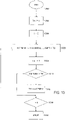
- the figure 7 illustrates an example of implementation of the CALIBR 35 function.
- These parameters include in particular an initial gain value, or IG value, that is to say a nominal gain value to be used in reception during future ultrasonic checks, and an amplitude threshold value (relative), or TG value, above which a defect is distinguished from an imperfection.
- IG value initial gain value
- amplitude threshold value relative
- TG value amplitude threshold value
- These parameters also include a definition of the different directions to be calibrated, ie the inspection directions to be used during future checks.
- a table is filled, for example of the type of the direction table DIRECT[ ], and/or data already contained in such a table is used.
- the gain values of the data-results take the nominal value IG, common to all the pairs, whatever the value of the angle.
- the nominal IG gain may be 11 decibels. If necessary, each element of an array of the array type RX_GAIN[ ] is filled with this nominal value IG.
- the data received may further comprise ultrasonic measurement data relating to a sample tube, in particular measurement data relating to one or more directional reflectors and a poly-directional reflector.
- ultrasonic measurement data relating to a sample tube
- measurement data relating to one or more directional reflectors and a poly-directional reflector.
- These data are stored in memory in the form of data sets, for example of the UNISET 37 and OMNISET 39 data set type. If necessary, tables of the N_AMP[ ] and H_AMP[ ] type are filled.
- the initialization step 70 is followed by a pre-processing step 72 which relates to data relating to the directional and/or poly-directional reflectors, for example the data from the OMNISET 39 and UNISET 37 sets described in relation to the figure 6 .
- the pre-processing 72 aims to improve the quality, from a calibration point of view, of the data relating to the reflectors.
- the pre-processing step 72 can comprise one or more steps of formatting data resulting from ultrasonic measurements, checking the consistency of these data, standardization, and more generally any statistical processing.
- the pre-processing step 72 comprises a sub-step during which the consistency of the data relating to the directional reflectors, for example the data from the UNISET 37 set, and/or the data relating to the poly-directional reflector, for example data from the OMNISET 38 game.
- these pairs are assigned modified amplitude values, calculated statistically from the original values. For example, each of the symmetrical pairs is assigned an amplitude value calculated as the average of the original amplitude values. Similar processing can be performed on the data set relating to the poly-directional reflector, for example the OMNISET 39 set.
- Tables 2.1 and 2.2 are similar to Tables 1.1 and 1.2, except that the amplitude values have been modified to take into account symmetry effects in the inspection directions.
- table 2.1 for example, it is taken into account that the lines corresponding to the angles 45° and 225° relate to the same notch, for example of the type of notch 15 of the picture 3 , assigning as amplitude value to each of these lines the mean value of the amplitudes of the corresponding lines in table 1.1.
- the pre-processing step 72 is followed by a statistical processing step 74 of the data relating to the poly-directional reflector and to the directional reflectors, for example the UNISET 37 and OMNISET 39 data respectively.
- the directional reflector data is interpolated using at least some of the poly-directional reflector data to complete the directional reflector data set. Value/amplitude pairs representative of responses of directional reflectors directed along different orientations are thus established.
- the interpolation of the pairs of the first set of data and of the second set of data make it possible to obtain pairs of a third set corresponding to standard amplitudes for ultrasonic inspections directed in a manner corresponding to at least some of the work directions of the reflector poly-directional.
- the data set relating to the directional reflectors, or UNISET set 37 comprises value/angle pairs each corresponding to a response amplitude of a directional reflector whose working direction, in the tube , is the direction of inspection defined by the angle.
- the processing includes a comparison step 76, which relates to the data resulting from the statistical processing of step 74. These are compared with target data, at least partly defined using the calibration parameters , to establish a set of data useful for calibration.
- These payload data comprise in particular a plurality of value/angle pairs which each relate to a modified gain value for a direction of inspection defined by the angle, or direction to be calibrated.
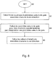
- the figure 8 illustrates an embodiment of a statistical processing or interpolation function, for use for example for the implementation of step 74 described in relation to the figure 7 .
- the interpolation begins with an initialization step 80, followed by a step 82 during which one or more value/angle pairs are established, each corresponding to a gain value associated with a directional parameter.
- the directional parameter corresponds to an inspection direction
- the gain value corresponds to a ratio of the response amplitudes of the directional reflector on the one hand, and of the poly-directional reflector, on the other hand, to an inspection whose direction is defined by the angle of the couple.
- an indexed table is used, which can be of dimension N, designated here as measured gain table, or MES_GAIN[ ] table.
- the gain values are calculated from the amplitude values of the couples from the data set relating to the directional reflectors, for example the UNISET 37 set, and from the amplitude values of the couples from the data set relating to the poly-directional reflector d corresponding angle, for example the OMNISET clearance, if necessary pre-processed.
- Angle values correspond to each other if they designate identical directions or, failing that, slightly inclined with respect to each other. This is the case, in particular, of identical angle values.
- a gain value is established using the amplitude value of the value/angle couple relative to the poly-directional reflector, the angle of which determines a direction corresponding to the direction of work of the directional reflector.
- the pairs relating to the directional reflectors may be less numerous than those relating to the poly-directional reflector, which makes it possible to use a small number of notches of different orientations from each other.
- the gain can be expressed in decibels, by relating the amplitude value of the directional reflector to that of the poly-directional reflector.
- Table 3.1 illustrates an example of the contents of the set of gains measured in the case of the notches and orifices described above.
- the left column of each line corresponds to the ratio, expressed in decibels, of the amplitude of the left column of Table 2.1 (notches) on the amplitude of the left column of table 2.2 (drilling) for the same angle value.
- step 84 during which additional value/angle pairs are established corresponding to gain values for inspection directions which differ from the working directions of the directional reflectors.
- an additional couple is established for each inspection direction which corresponds to a working direction of the poly-directional reflector.
- the gain values of the value/angle pairs established in the previous step are interpolated for working directions of the directional and poly-directional reflectors which correspond to each other.
- the interpolation can implement a linear regression method for example.
- the linear regression method works well with the number of notches described here, i.e. 4.
- Other interpolation methods can be used.
- more complex methods for example of order 2 can be considered when the number of reflectors is less (than 8).
- the interpolation results can be stored in an array, for example an indexed SIM_GAIN[ ] array of dimension N, whose index corresponds to the inspection directions in the DIRECT[ ] array.
- Table 3.2 illustrates an example of the contents of such a table.
- the gain values indicated in the other lines relate to the inspection directions to be calibrated and result from an interpolation of the data obtained with the working directions of the notches.
- the interpolation here is carried out by linear regression.
- the gain value of 2.0 decibels obtained in the 25° row for the left column is calculated from the gain value in the 0° row of Table 3.1, to which is added the difference in the gains of the 45° and 0° lines compared to the angular difference between these lines multiplied by the angular difference between the 25° line and the 0° line.
- the gain values of the couples of steps 82 and 84 are used together with the amplitude values of the couples relating to the poly-directional reflector to establish a set of value/angle pairs corresponding to amplitude values each associated with a directional parameter.
- the amplitude value of each value/angle pair of the data set relating to the directional reflector is applied to the gain value whose angle corresponds.
- the result is stored in the form of a new value/angle couple which can be seen as a response amplitude value of a virtual directional reflector associated with the orientation of this reflector as a directional parameter.
- the set of pairs obtained can be stored as a new data set, comprising for example an indexed SIM_AMP[ ] table of dimension N, or complete the data set relating to the directional reflectors, for example a table of the type array N_AMP[ ].
- Table 3.3 illustrates the result of step 86, as it may be contained in the table SIM_AMP[] for example.
- the amplitude value is calculated from the corresponding row amplitude for the orifice in Table 2.2 and the corresponding row simulated gain in Table 3.2.
- the 64.3% value of the 25° line is obtained from the corresponding amplitude value in Table 2.2 multiplied by the value 10 raised to a power of the gain divided by 20.
- the gain to be adjusted for each direction of inspection can then be calculated by correcting the initial gain value, for example the IG gain, by the ratio, in decibels, of the amplitude value resulting from the interpolation on the value d target amplitude, for example the TS value.
- Table 4.1 illustrates an example of gain values thus obtained for values of IG at 11 decibels and TG at 80%.
- Table 4.2 illustrates that the tuning gain values obtained for the outside of the sample tube can be expressed relative to the gain values obtained for the inside of the tube.
- the figure 9 illustrates an embodiment of a comparative function capable of establishing a set of gain values from pairs relating to directional and poly-directional reflectors respectively, as stored in the H_AMP[ ] and N_AMP[ ] arrays described later high.
- the function initializes.
- an indexed array of N-dimensional data, or gain array MES_GAIN[ ] is defined.
- a loop structure is started by initializing the loop counter, here the dummy variable i.
- the loop counter is incremented.
- it is checked if there is an amplitude value in column i of the N_AMP[] table by checking if the N_AMP[i] value stored in column i is greater than zero.
- a gain value is calculated as a ratio for the index value i of the values stored in the N_AMP[ ] array to the value stored in the H_AMP[ ] array (step 910).
- the gain is calculated in decibels.
- the calculated value is stored in column i of the gain table MES_GAIN[ ].
- step 912 the zero value is assigned to element i of the gain array MES_GAIN[ ] during step 912.
- the loop counter i has reached the value N indicative of end of loop (step 914). If yes, the function stops at 916. Otherwise, we return to step 906.
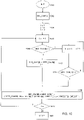
- the figure 10 illustrates an embodiment of an interpolation function capable of calculating value/angle pairs corresponding to gain values by interpolation of value/angle pairs corresponding to gain values each associated with a directional parameter, as stored in the MES_GAIN[ ] array.
- a new indexed array SIM_GAIN[] of dimension N is declared to receive calculation data.
- step 1004 three dummy variables i, j and k are initialized.
- the variable i is incremented as a loop counter, in step 1006.
- step 1008 it is checked whether the element i of the first array of gains MES_GAIN[] contains a value.
- step 1010 the value MES_GAIN[i] is stored in column i of the second table SIM_GAIN[], and variable j is assigned the value of variable i.
- step 1012 the variable k is assigned a value incremented by the first loop counter i. And, during a step 1014, it is checked whether the first gain table MES_GAIN[] contains a non-zero value in its column designated by the value of the variable k. Otherwise, we return to step 1012.
- a new gain value is established (step 1016) which is stored in column i of the second gain table SIM_GAIN[ ] from the following formula (A):
- SIM _ GAIN I : MY _ GAIN I + MY _ GAIN k ⁇ MY _ GAIN I / DIRECT k ⁇ DIRECT I ⁇ DIRECT I ⁇ DIRECT I
- step 1018 It is then tested, during step 1018, whether the loop counter i has reached its final value n. If yes, we stop at a step 1020. Otherwise we return to step 1006.
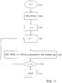
- the figure 11 illustrates an embodiment of a simulation function capable of calculating value/angle pairs corresponding to amplitude values from value/angle pairs corresponding to gain values each associated with a directional parameter, as stored in the SIM_GAIN[ ] array, for example.
- a new indexed array SIM_AMP[] is declared, for example of dimensions N, intended to receive calculation data.
- a dummy variable i is initialized as a loop counter.
- the counter i is incremented, at step 1106.
- the i th element of the array SIM_AMP[ ] is assigned a value calculated on the basis of the following formula (B):
- SIM _ GPA I : H _ GPA I ⁇ power 10 , SIM _ GAIN I / 20
- step 1110 it is checked whether the value of the loop counter i is less than the value N.
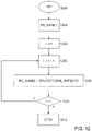
- the figure 12 illustrates an embodiment of a conversion function capable of calculating value/angle pairs corresponding to gain values each associated with a directional parameter from amplitude values as stored in the table SIM_AMP[ ].
- the function begins with an initialization step 1200.
- an indexed array RX_GAIN[ ] of dimension N intended to receive the calculation data is created.
- step 1204 a dummy variable i is initialized as a loop counter.
- step 1210 it is tested whether the loop counter is strictly less than the end of loop value N. If yes, then it returns to step 1206. Otherwise, the function stops in a step 1212.
- the CALIBR function 35 works on the first set of data relating to one or more directional reflectors provided in the sample tube, and on the second set of data relating to a poly-directional reflector provided in this tube.
- Obtaining data relating to these reflectors can be done conventionally. For example, for each measurement, an ultrasonic shot is carried out per working direction of a directional reflector, and in a manner corresponding to this direction. And, for each measurement, as many shots are made as there are inspection directions or as working directions of the poly-directional reflector.
- the use of an ultrasonic transducer of the multi-element type facilitates the measurements: the delay laws make it possible to orient the ultrasonic beam without modifying the relative position of the transducer with respect to the sample tube.
- an inspection configuration analogous to that used in production is preferably used for calibration. This greatly improves the inspections carried out in production.
- FAAST II electronics e.g. shown at http://www.socomate.com/2-products/phased-array/faast-ii-2d-matrix -active-8x40e-2mhz-21.htm
- GRP installation for example shown at http://www.ge-mcs.com/en /ultrasound/integrated-systems/tubepipe-grp.html
- the quality of the calibration data established by the CALIBR function 35 is influenced by the quality of the original data, from which the first and second sets of data are formed.
- the original data comes from ultrasonic measurements, performed on the sample tube.
- the directional reflectors for example the notches 7 described in relation to the figures 3 to 5 , generally have a larger dimension than the others, which corresponds to the working direction of the reflector. This property can be used to obtain several values of amplitude of reflection of a particular reflector for the same direction of inspection.
- the length of the notch is generally the subject of a minimum specification: it makes it possible to ensure, given a number of shots per unit of advance of the tube, the detection of a notch of a minimum length with a configurable number of stitches.
- a representative amplitude value should be established, for use in the dataset relating to this directional reflector. Taking the maximum amplitude value as a representative value is not satisfactory: this amounts to qualifying only large imperfections as faults. And taking the average amplitude value is not either: there is a risk of not detecting the reflectors if they are widely dispersed.
- the CALIBR function 35 is capable of extracting from such a set of amplitude values a characteristic amplitude value of the directional reflector.
- This characteristic value is established as a threshold value which makes it possible to obtain a predetermined number of successive values of amplitude greater than this threshold value.
- the number in question corresponds to a resolution. It is configurable.
- the measurements in the tables in appendix 1, for example, correspond to a resolution of 3 successive points.
- the figure 13 illustrates an embodiment of an extraction function for use in obtaining a characteristic amplitude value of a directional reflector from a set of amplitude values associated with a same direction of inspection.
- an initialization step 1300 receives as parameter an integer value R as resolution value.
- R an integer value
- a set of amplitude values is also received, for example in the form of an indexed array of dimension k, or array AMP[k]. These amplitude values relate to the same directional reflector and the same direction of inspection.
- a variable TH is defined which is initialized to the zero value. Then we start a loop structure using a dummy variable i as a counter. The counter is initialized (step 1304). During the next step 1306, the minimum value AMPMINI is determined from among the amplitude values stored in the array AMP[k] at element i, at element i+R and in all the elements between these last.
- step 1308 the loop counter is incremented.
- step 1310 it is checked whether the minimum amplitude value AMPMINI is greater than the value TH. If yes, then, at step 1312, the threshold value TH takes the value of the minimum amplitude AMPMINI. Otherwise, as at the end of step 1312, it is checked whether the loop counter has reached its end value k (step 1314). If yes, then the function stops at 1316. Otherwise, the process returns to 1306.
- the final value TH corresponds to a threshold value which characterizes the directional reflector.
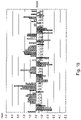
- figure 14 and 15 illustrate the performance of the calibration aid device in the case of a sample tube 88.9 millimeters in diameter and 7.61 millimeters thick.
- the graph of the figure 14 shows amplitude values obtained for external (real) notches oriented around 360° with a step of 5° in the case of a calibration carried out with the aid device described, parameterized with a threshold amplitude value at 60%. The check was carried out 10 times, and the most unfavorable amplitude value was considered, that is to say the experimental value furthest from the target amplitude value.
- the graph of the figure 15 is analogous to the figure 14 except that it shows the difference between the measured values and the calibrated values in decibels.
- the figure 15 shows a dispersion value of approximately 6.4 decibels. This value is compatible with industrial requirements.
- the module uses measured data for ultrasonic inspections carried out on a poly-directional reflector, in particular a hole, and on one or more directional reflectors, for example of the notch type.
- the inspection directions used for the measurements preferably correspond to the inspection directions for use in production: this greatly improves the calibration.
- Each notch is directed along a respective direction of inspection.
- fewer directional reflectors are used than there are inspection directions to be calibrated: the inspection directions which do not correspond to any working direction of a directional reflector are calibrated using the amplitudes measured with the poly-directional reflector, for corresponding working direction.
- the amplitudes measured on the poly-directional reflector are corrected on the basis of a comparison of the amplitude values obtained, for the same direction of inspection, on the directional reflectors and the poly-directional reflector. This makes it possible to continue to use the directional reflectors, in particular the notches, as reference defects, the geometric characteristics of which can, if necessary, be the subject of a specification, while reducing their number.
- the invention has essentially been presented in the form of a device. It can also be seen as a method for aiding the calibration of a device for checking metallurgical products according to claim 12.
- a first set of data is stored in the form of value/angle pairs, the first set of data relating to a poly-directional reflector provided in the metallurgical product, the value/angle pairs of the first set of data corresponding to measured return amplitudes resulting from ultrasonic shots directed, in the metallurgical product, along at least some directions work of the poly-directional reflector corresponding to said angle.
- a second data set is also stored in the form of value/angle pairs, the second data set relating to a directional reflector provided in the metallurgical product, the second data set comprising, for the directional reflector, a corresponding value/angle pair at a measured return amplitude resulting from an ultrasonic shot directed along a working direction of the reflector corresponding to said angle.
- a third set of data is established, in the form of value/angle pairs, by interpolation of the pairs of the first set of data and of the second set of data, the pairs of the third set corresponding to standard amplitudes for ultrasonic shots directed in such a way corresponding to at least some of the working directions of the poly-directional reflector.
- the invention may also be expressed in the form of a computer program product according to claim 13.
- the invention is not limited to the embodiments described above, by way of a single example, but encompasses all variants that may be considered by those skilled in the art within the scope of the appended claims.
- Annex 1 original data
- Table 1.1 Notch Responses Direction Internal External 0 85.0 70.0 45 71.0 50.0 90 95.0 32.0 135 81.0 52.0 180 81.0 63.0 225 76.0 52.0 270 86.0 40.0 315 85.0 58.0
- Table 1.2 Orifice responses (in amplitude) Direction Internal External Direction Internal External 0 93.0 52.0 180 50.0 41.0 5 90.0 53.0 185 48.0 39.0 10 80.0 48.0 190 41.0 34.0 15 65.0 38.0 195 32.0 26.0 20 55.0 32.0 200 33.0 31.0 25 64.0 37.0 205 38.0 36.0 30 68.0 39.0 210 40.0 35.0 35 67.0 37.0 215 37.0 31.0 40 65.0 38.0 220 37.0 34.0 45 66.0 39.0 225 43.0 35.0 50 69.0 41.0 230 50.0 34.0 55 68.0 38.0 235 52.0 34.0 60 64.0 36.0 240 52.0 33.0 65 58.0 35.0 245 47.0 31.0 70 52.0 34.0 250 44.0 26.0 75
- Annex 2 data resulting from pre-processing
- Table 2.1 Notch responses (in amplitude) Direction Internal External 0 83.0 66.5 45 73.5 51.0 90 90.5 36.0 135 83.0 55.0 180 83.0 66.5 225 73.5 51.0 270 90.5 36.0 315 83.0 55.0
- Table 2.2 Orifice responses (in amplitude) Direction Internal External Direction Internal External 0 71.5 46.5 180 71.5 46.5 5 69.0 46.0 185 69.0 46.0 10 60.5 41.0 190 60.5 41.0 15 48.5 32.0 195 48.5 32.0 20 44.0 31.5 200 44.0 31.5 25 51.0 36.5 205 51.0 36.5 30 54.0 37.0 210 54.0 37.0 35 52.0 34.0 215 52.0 34.0 40 51.0 36.0 220 51.0 36.0 45 54.5 37.0 225 54.5 37.0 50 59.5 37.5 230 59.5 37.5 55 60.0 36.0 235 60.0 36.0 60 58.0 34.5 240 58.0 34.5 65 52.5 33.0 245 52.5 33.0 70 48.0 30.0
- Table 3.1 ratios of measured responses (in gain) Direction Internal External 0 1.30 3.11 45 2.60 2.79 90 1.46 -1.13 135 2.39 2.88 180 1.30 3.11 228 2.60 2.79 270 1.46 -1.13 315 2.39 2.88
- Table 3.2 interpolation of responses (in gain) Direction Internal External Direction Internal External 0 1.3 3.1 180 1.3 3.1 5 1.4 3.1 185 1.4 3.1 10 1.6 3.0 190 1.6 3.0 15 1.7 3.0 195 1.7 3.0 20 1.9 3.0 200 1.9 3.0 25 2.0 2.9 205 2.0 2.9 30 2.2 2.9 210 2.2 2.9 35 2.3 2.9 215 2.3 2.9 40 2.5 2.8 220 2.5 2.8 45 2.6 2.8 225 2.6 2.8 50 2.5 2.4 230 2.7 2.8 55 2.3 1.9 235 2.9 2.7 60 2.2 1.5 240 2.3 2.7 65 2.1 1.0 245 2.2 2.6 70 2.0 0.6 250 2.0 2.6 75 1.8 0.2 255 1.9 2.6 80 1.7
- Appendix 4 gain values to be set
- Table 4.1 absolute values Direction Internal External Direction Internal External 0 34.7 36.6 180 34.7 36.6 5 34.8 36.7 185 34.8 36.7 10 35.8 37.8 190 35.8 37.8 15 37.6 40.0 195 37.6 40.0 20 38.3 40.1 200 38.3 40.1 25 36.9 38.9 205 36.9 38.9 30 36.3 38.8 210 36.3 38.8 35 36.4 39.6 215 36.4 39.6 40 36.5 39.1 220 36.5 39.1 45 35.7 38.9 225 35.7 38.9 50 35.1 39.2 230 34.8 38.8 55 35.2 40.0 235 34.6 39.2 60 35.6 40.8 240 35.5 39.6 65 36.6 41.6 245 36.5 40.0 70 37.5 42.9 250 37.4 40.9 75 36.1 42.9 255 36.0 40.5 80 34.8 43.0 260 34.8 40.2 85 34.1 42.2 265 34.1 39.0 90 33.9 41.9 270 33.9 38.3 95 33.9 41.7 275
Landscapes
- Physics & Mathematics (AREA)
- Health & Medical Sciences (AREA)
- Life Sciences & Earth Sciences (AREA)
- Chemical & Material Sciences (AREA)
- Analytical Chemistry (AREA)
- Biochemistry (AREA)
- General Health & Medical Sciences (AREA)
- General Physics & Mathematics (AREA)
- Immunology (AREA)
- Pathology (AREA)
- Engineering & Computer Science (AREA)
- Signal Processing (AREA)
- Probability & Statistics with Applications (AREA)
- Investigating Or Analyzing Materials By The Use Of Ultrasonic Waves (AREA)
- Ultra Sonic Daignosis Equipment (AREA)
Applications Claiming Priority (2)
| Application Number | Priority Date | Filing Date | Title |
|---|---|---|---|
| FR1552770A FR3034545B1 (fr) | 2015-03-31 | 2015-03-31 | Outils pour l'etalonnage d'un dispositif de controle par ultrasons |
| PCT/EP2016/056698 WO2016156262A1 (fr) | 2015-03-31 | 2016-03-25 | Outils pour l'etalonnage d'un dispositif de controle par ultrasons |
Publications (2)
| Publication Number | Publication Date |
|---|---|
| EP3278097A1 EP3278097A1 (fr) | 2018-02-07 |
| EP3278097B1 true EP3278097B1 (fr) | 2022-05-04 |
Family
ID=54140540
Family Applications (1)
| Application Number | Title | Priority Date | Filing Date |
|---|---|---|---|
| EP16714817.0A Active EP3278097B1 (fr) | 2015-03-31 | 2016-03-25 | Outils pour l'etalonnage d'un dispositif de controle par ultrasons |
Country Status (13)
| Country | Link |
|---|---|
| US (1) | US10690633B2 (zh) |
| EP (1) | EP3278097B1 (zh) |
| JP (1) | JP6765382B2 (zh) |
| CN (1) | CN107430097B (zh) |
| AR (1) | AR104153A1 (zh) |
| AU (1) | AU2016240373B2 (zh) |
| BR (1) | BR112017020680B1 (zh) |
| CA (1) | CA2980826A1 (zh) |
| FR (1) | FR3034545B1 (zh) |
| RU (1) | RU2705765C2 (zh) |
| SA (1) | SA517390041B1 (zh) |
| UA (1) | UA123005C2 (zh) |
| WO (1) | WO2016156262A1 (zh) |
Families Citing this family (3)
| Publication number | Priority date | Publication date | Assignee | Title |
|---|---|---|---|---|
| BR102018015331A2 (pt) * | 2018-07-26 | 2020-02-04 | Vallourec Solucoes Tubulares Do Brasil S A | método para avaliação do nível inclusional em tubos de aço utilizando transdutor de alta frequência na inspeção ultrassônica automática |
| FR3096286B1 (fr) * | 2019-05-20 | 2021-06-11 | Vallourec Tubes France | Procédé de génération d’un indice de compatibilité entre deux extrémités de deux tubes, tube muni d’un indicateur de compatibilité |
| CN115905961B (zh) * | 2023-03-09 | 2023-05-05 | 广东广宇科技发展有限公司 | 一种基于多源数据的管道缺陷分析方法 |
Family Cites Families (17)
| Publication number | Priority date | Publication date | Assignee | Title |
|---|---|---|---|---|
| US4576034A (en) * | 1984-02-27 | 1986-03-18 | Westinghouse Electric Corp. | Adjustable radius apparatus for calibrating ultrasonic transducer array |
| JPS6170455A (ja) * | 1984-09-14 | 1986-04-11 | Tokyo Keiki Co Ltd | 電縫管溶接部探傷における較正走査装置 |
| IN169006B (zh) * | 1986-06-26 | 1991-08-10 | Westinghouse Electric Corp | |
| US4757716A (en) * | 1986-06-26 | 1988-07-19 | Westinghouse Electric Corp. | Boresonic inspection system |
| JPH11230948A (ja) * | 1998-02-17 | 1999-08-27 | Sumitomo Chem Co Ltd | 超音波探傷方法 |
| FR2833706B1 (fr) | 2001-12-13 | 2004-07-23 | Setval | Controle non destructif a capteurs ultrasonores, de produits de metallurgie |
| JP4111902B2 (ja) * | 2003-09-30 | 2008-07-02 | 日立Geニュークリア・エナジー株式会社 | 自動検査システム |
| US7389693B2 (en) * | 2006-02-15 | 2008-06-24 | General Electric Company | Methods and apparatus for porosity measurement |
| CN1912612A (zh) * | 2006-08-15 | 2007-02-14 | 天津工业大学 | 一种多相流物质的检测方法及检测装置 |
| CA2593894C (en) * | 2006-12-01 | 2016-11-08 | Roentgen Technische Dienst B.V. | A method for configuring an array of transducers in an ultrasonic test apparatus |
| US9282945B2 (en) * | 2009-04-14 | 2016-03-15 | Maui Imaging, Inc. | Calibration of ultrasound probes |
| US9279786B2 (en) * | 2011-08-23 | 2016-03-08 | Olympus Ndt | Method of and an apparatus conducting calibration for phased-array shear wave channels inspecting square bars |
| RU124397U1 (ru) * | 2012-03-30 | 2013-01-20 | Открытое акционерное общество "Радиоавионика" | Устройство для калибровки ультразвукового зонда |
| US8839673B2 (en) * | 2012-05-02 | 2014-09-23 | Siemens Energy, Inc. | System and method for industrial ultrasonic inspection using phased array probe and distance-gain-size flaw sizing |
| FR3000212B1 (fr) | 2012-12-21 | 2015-01-16 | V & M France | Dispositif et procede de controle non destructif de profiles metalliques |
| RU2530181C1 (ru) * | 2013-05-15 | 2014-10-10 | Общество с ограниченной ответственностью "Научно-производственный центр неразрушающего контроля "ЭХО+" | Способ калибровки ультразвуковой антенной решетки, установленной на призму |
| US10908122B2 (en) * | 2016-03-31 | 2021-02-02 | Olympus America Inc. | Total focusing method adaptively corrected by using plane wave |
-
2015
- 2015-03-31 FR FR1552770A patent/FR3034545B1/fr not_active Expired - Fee Related
-
2016
- 2016-03-25 CN CN201680019666.9A patent/CN107430097B/zh not_active Expired - Fee Related
- 2016-03-25 JP JP2017551223A patent/JP6765382B2/ja not_active Expired - Fee Related
- 2016-03-25 WO PCT/EP2016/056698 patent/WO2016156262A1/fr active Application Filing
- 2016-03-25 BR BR112017020680-3A patent/BR112017020680B1/pt not_active IP Right Cessation
- 2016-03-25 UA UAA201709483A patent/UA123005C2/uk unknown
- 2016-03-25 US US15/562,665 patent/US10690633B2/en not_active Expired - Fee Related
- 2016-03-25 CA CA2980826A patent/CA2980826A1/fr not_active Abandoned
- 2016-03-25 EP EP16714817.0A patent/EP3278097B1/fr active Active
- 2016-03-25 RU RU2017133761A patent/RU2705765C2/ru active
- 2016-03-25 AU AU2016240373A patent/AU2016240373B2/en not_active Ceased
- 2016-03-31 AR ARP160100867A patent/AR104153A1/es active IP Right Grant
-
2017
- 2017-09-27 SA SA517390041A patent/SA517390041B1/ar unknown
Also Published As
| Publication number | Publication date |
|---|---|
| AU2016240373A1 (en) | 2017-11-09 |
| RU2017133761A3 (zh) | 2019-06-06 |
| UA123005C2 (uk) | 2021-02-03 |
| EP3278097A1 (fr) | 2018-02-07 |
| JP2018510352A (ja) | 2018-04-12 |
| BR112017020680B1 (pt) | 2021-10-19 |
| CN107430097A (zh) | 2017-12-01 |
| SA517390041B1 (ar) | 2021-03-01 |
| FR3034545B1 (fr) | 2018-05-11 |
| US10690633B2 (en) | 2020-06-23 |
| RU2705765C2 (ru) | 2019-11-11 |
| CA2980826A1 (fr) | 2016-10-06 |
| BR112017020680A2 (pt) | 2018-06-26 |
| AR104153A1 (es) | 2017-06-28 |
| CN107430097B (zh) | 2020-06-09 |
| FR3034545A1 (fr) | 2016-10-07 |
| JP6765382B2 (ja) | 2020-10-07 |
| US20180106768A1 (en) | 2018-04-19 |
| WO2016156262A1 (fr) | 2016-10-06 |
| RU2017133761A (ru) | 2019-03-29 |
| AU2016240373B2 (en) | 2021-05-20 |
Similar Documents
| Publication | Publication Date | Title |
|---|---|---|
| EP3004864B1 (fr) | Procede d'inspection par transmission d'ultrasons ameliore | |
| EP3224611B1 (fr) | Procédé de détection et de caractérisation par ultrasons de défauts dans un matériau hétérogène | |
| EP3278097B1 (fr) | Outils pour l'etalonnage d'un dispositif de controle par ultrasons | |
| EP1454132B1 (fr) | Controle non destructif a capteurs ultrasonores de produits de metallurgie | |
| WO2014147344A1 (fr) | Dispositif et procédé de contrôle non destructif de produits tubulaires avec des réseaux en phase électroacoustiques, notamment sur site | |
| EP2577224A1 (fr) | Procédé et dispositif d'aide au contrôle en production de la traversabilité de tubes | |
| EP3847450B1 (fr) | Procede de detection et de caracterisation par ultrasons de defauts dans un materiau heterogene | |
| WO2014096700A1 (fr) | Dispositif et procede de controle non destructif de profiles metalliques | |
| WO2018234678A1 (fr) | Contrôle non destructif pour produit tubulaire à forme complexe | |
| FR2796153A1 (fr) | Controle non destructif a capteurs ultrasonores repartis | |
| CA3186352A1 (fr) | Procede de controle dynamique par imagerie ultrasonore | |
| EP3555612B1 (fr) | Dispositif et procédé de caractérisation non-destructive d'un matériau par ultrasons | |
| WO2024121512A1 (fr) | Procédé de détection de fissure dans une conduite tubulaire | |
| EP4384775A1 (fr) | Procédé de reconstruction d'un profil d'épaisseur de pièce à controler | |
| EP2166306B1 (fr) | Dispositif et procédé de contrôle de dimensions d'une gaine d'un crayon d'une grappe de commande pour un coeur de réacteur nucléaire | |
| EP4127692A1 (fr) | Contrôle non destructif d'une pièce mécanique en un matériau polycristallin |
Legal Events
| Date | Code | Title | Description |
|---|---|---|---|
| STAA | Information on the status of an ep patent application or granted ep patent |
Free format text: STATUS: THE INTERNATIONAL PUBLICATION HAS BEEN MADE |
|
| PUAI | Public reference made under article 153(3) epc to a published international application that has entered the european phase |
Free format text: ORIGINAL CODE: 0009012 |
|
| STAA | Information on the status of an ep patent application or granted ep patent |
Free format text: STATUS: REQUEST FOR EXAMINATION WAS MADE |
|
| 17P | Request for examination filed |
Effective date: 20170925 |
|
| AK | Designated contracting states |
Kind code of ref document: A1 Designated state(s): AL AT BE BG CH CY CZ DE DK EE ES FI FR GB GR HR HU IE IS IT LI LT LU LV MC MK MT NL NO PL PT RO RS SE SI SK SM TR |
|
| AX | Request for extension of the european patent |
Extension state: BA ME |
|
| DAV | Request for validation of the european patent (deleted) | ||
| DAX | Request for extension of the european patent (deleted) | ||
| STAA | Information on the status of an ep patent application or granted ep patent |
Free format text: STATUS: EXAMINATION IS IN PROGRESS |
|
| 17Q | First examination report despatched |
Effective date: 20190605 |
|
| STAA | Information on the status of an ep patent application or granted ep patent |
Free format text: STATUS: EXAMINATION IS IN PROGRESS |
|
| GRAP | Despatch of communication of intention to grant a patent |
Free format text: ORIGINAL CODE: EPIDOSNIGR1 |
|
| STAA | Information on the status of an ep patent application or granted ep patent |
Free format text: STATUS: GRANT OF PATENT IS INTENDED |
|
| INTG | Intention to grant announced |
Effective date: 20210917 |
|
| GRAJ | Information related to disapproval of communication of intention to grant by the applicant or resumption of examination proceedings by the epo deleted |
Free format text: ORIGINAL CODE: EPIDOSDIGR1 |
|
| STAA | Information on the status of an ep patent application or granted ep patent |
Free format text: STATUS: EXAMINATION IS IN PROGRESS |
|
| GRAP | Despatch of communication of intention to grant a patent |
Free format text: ORIGINAL CODE: EPIDOSNIGR1 |
|
| STAA | Information on the status of an ep patent application or granted ep patent |
Free format text: STATUS: GRANT OF PATENT IS INTENDED |
|
| INTC | Intention to grant announced (deleted) | ||
| INTG | Intention to grant announced |
Effective date: 20211119 |
|
| RAP3 | Party data changed (applicant data changed or rights of an application transferred) |
Owner name: VALLOUREC TUBES FRANCE |
|
| GRAS | Grant fee paid |
Free format text: ORIGINAL CODE: EPIDOSNIGR3 |
|
| GRAA | (expected) grant |
Free format text: ORIGINAL CODE: 0009210 |
|
| STAA | Information on the status of an ep patent application or granted ep patent |
Free format text: STATUS: THE PATENT HAS BEEN GRANTED |
|
| AK | Designated contracting states |
Kind code of ref document: B1 Designated state(s): AL AT BE BG CH CY CZ DE DK EE ES FI FR GB GR HR HU IE IS IT LI LT LU LV MC MK MT NL NO PL PT RO RS SE SI SK SM TR |
|
| REG | Reference to a national code |
Ref country code: GB Ref legal event code: FG4D Free format text: NOT ENGLISH |
|
| REG | Reference to a national code |
Ref country code: CH Ref legal event code: EP |
|
| REG | Reference to a national code |
Ref country code: AT Ref legal event code: REF Ref document number: 1489571 Country of ref document: AT Kind code of ref document: T Effective date: 20220515 |
|
| REG | Reference to a national code |
Ref country code: IE Ref legal event code: FG4D Free format text: LANGUAGE OF EP DOCUMENT: FRENCH Ref country code: DE Ref legal event code: R096 Ref document number: 602016071732 Country of ref document: DE |
|
| REG | Reference to a national code |
Ref country code: LT Ref legal event code: MG9D |
|
| REG | Reference to a national code |
Ref country code: NL Ref legal event code: MP Effective date: 20220504 |
|
| REG | Reference to a national code |
Ref country code: AT Ref legal event code: MK05 Ref document number: 1489571 Country of ref document: AT Kind code of ref document: T Effective date: 20220504 |
|
| PG25 | Lapsed in a contracting state [announced via postgrant information from national office to epo] |
Ref country code: SE Free format text: LAPSE BECAUSE OF FAILURE TO SUBMIT A TRANSLATION OF THE DESCRIPTION OR TO PAY THE FEE WITHIN THE PRESCRIBED TIME-LIMIT Effective date: 20220504 Ref country code: PT Free format text: LAPSE BECAUSE OF FAILURE TO SUBMIT A TRANSLATION OF THE DESCRIPTION OR TO PAY THE FEE WITHIN THE PRESCRIBED TIME-LIMIT Effective date: 20220905 Ref country code: NO Free format text: LAPSE BECAUSE OF FAILURE TO SUBMIT A TRANSLATION OF THE DESCRIPTION OR TO PAY THE FEE WITHIN THE PRESCRIBED TIME-LIMIT Effective date: 20220804 Ref country code: NL Free format text: LAPSE BECAUSE OF FAILURE TO SUBMIT A TRANSLATION OF THE DESCRIPTION OR TO PAY THE FEE WITHIN THE PRESCRIBED TIME-LIMIT Effective date: 20220504 Ref country code: LT Free format text: LAPSE BECAUSE OF FAILURE TO SUBMIT A TRANSLATION OF THE DESCRIPTION OR TO PAY THE FEE WITHIN THE PRESCRIBED TIME-LIMIT Effective date: 20220504 Ref country code: HR Free format text: LAPSE BECAUSE OF FAILURE TO SUBMIT A TRANSLATION OF THE DESCRIPTION OR TO PAY THE FEE WITHIN THE PRESCRIBED TIME-LIMIT Effective date: 20220504 Ref country code: GR Free format text: LAPSE BECAUSE OF FAILURE TO SUBMIT A TRANSLATION OF THE DESCRIPTION OR TO PAY THE FEE WITHIN THE PRESCRIBED TIME-LIMIT Effective date: 20220805 Ref country code: FI Free format text: LAPSE BECAUSE OF FAILURE TO SUBMIT A TRANSLATION OF THE DESCRIPTION OR TO PAY THE FEE WITHIN THE PRESCRIBED TIME-LIMIT Effective date: 20220504 Ref country code: ES Free format text: LAPSE BECAUSE OF FAILURE TO SUBMIT A TRANSLATION OF THE DESCRIPTION OR TO PAY THE FEE WITHIN THE PRESCRIBED TIME-LIMIT Effective date: 20220504 Ref country code: BG Free format text: LAPSE BECAUSE OF FAILURE TO SUBMIT A TRANSLATION OF THE DESCRIPTION OR TO PAY THE FEE WITHIN THE PRESCRIBED TIME-LIMIT Effective date: 20220804 Ref country code: AT Free format text: LAPSE BECAUSE OF FAILURE TO SUBMIT A TRANSLATION OF THE DESCRIPTION OR TO PAY THE FEE WITHIN THE PRESCRIBED TIME-LIMIT Effective date: 20220504 |
|
| PG25 | Lapsed in a contracting state [announced via postgrant information from national office to epo] |
Ref country code: RS Free format text: LAPSE BECAUSE OF FAILURE TO SUBMIT A TRANSLATION OF THE DESCRIPTION OR TO PAY THE FEE WITHIN THE PRESCRIBED TIME-LIMIT Effective date: 20220504 Ref country code: PL Free format text: LAPSE BECAUSE OF FAILURE TO SUBMIT A TRANSLATION OF THE DESCRIPTION OR TO PAY THE FEE WITHIN THE PRESCRIBED TIME-LIMIT Effective date: 20220504 Ref country code: LV Free format text: LAPSE BECAUSE OF FAILURE TO SUBMIT A TRANSLATION OF THE DESCRIPTION OR TO PAY THE FEE WITHIN THE PRESCRIBED TIME-LIMIT Effective date: 20220504 Ref country code: IS Free format text: LAPSE BECAUSE OF FAILURE TO SUBMIT A TRANSLATION OF THE DESCRIPTION OR TO PAY THE FEE WITHIN THE PRESCRIBED TIME-LIMIT Effective date: 20220904 |
|
| PG25 | Lapsed in a contracting state [announced via postgrant information from national office to epo] |
Ref country code: SM Free format text: LAPSE BECAUSE OF FAILURE TO SUBMIT A TRANSLATION OF THE DESCRIPTION OR TO PAY THE FEE WITHIN THE PRESCRIBED TIME-LIMIT Effective date: 20220504 Ref country code: SK Free format text: LAPSE BECAUSE OF FAILURE TO SUBMIT A TRANSLATION OF THE DESCRIPTION OR TO PAY THE FEE WITHIN THE PRESCRIBED TIME-LIMIT Effective date: 20220504 Ref country code: RO Free format text: LAPSE BECAUSE OF FAILURE TO SUBMIT A TRANSLATION OF THE DESCRIPTION OR TO PAY THE FEE WITHIN THE PRESCRIBED TIME-LIMIT Effective date: 20220504 Ref country code: EE Free format text: LAPSE BECAUSE OF FAILURE TO SUBMIT A TRANSLATION OF THE DESCRIPTION OR TO PAY THE FEE WITHIN THE PRESCRIBED TIME-LIMIT Effective date: 20220504 Ref country code: DK Free format text: LAPSE BECAUSE OF FAILURE TO SUBMIT A TRANSLATION OF THE DESCRIPTION OR TO PAY THE FEE WITHIN THE PRESCRIBED TIME-LIMIT Effective date: 20220504 Ref country code: CZ Free format text: LAPSE BECAUSE OF FAILURE TO SUBMIT A TRANSLATION OF THE DESCRIPTION OR TO PAY THE FEE WITHIN THE PRESCRIBED TIME-LIMIT Effective date: 20220504 |
|
| REG | Reference to a national code |
Ref country code: DE Ref legal event code: R097 Ref document number: 602016071732 Country of ref document: DE |
|
| PLBE | No opposition filed within time limit |
Free format text: ORIGINAL CODE: 0009261 |
|
| STAA | Information on the status of an ep patent application or granted ep patent |
Free format text: STATUS: NO OPPOSITION FILED WITHIN TIME LIMIT |
|
| PG25 | Lapsed in a contracting state [announced via postgrant information from national office to epo] |
Ref country code: AL Free format text: LAPSE BECAUSE OF FAILURE TO SUBMIT A TRANSLATION OF THE DESCRIPTION OR TO PAY THE FEE WITHIN THE PRESCRIBED TIME-LIMIT Effective date: 20220504 |
|
| 26N | No opposition filed |
Effective date: 20230207 |
|
| PG25 | Lapsed in a contracting state [announced via postgrant information from national office to epo] |
Ref country code: SI Free format text: LAPSE BECAUSE OF FAILURE TO SUBMIT A TRANSLATION OF THE DESCRIPTION OR TO PAY THE FEE WITHIN THE PRESCRIBED TIME-LIMIT Effective date: 20220504 |
|
| REG | Reference to a national code |
Ref country code: DE Ref legal event code: R119 Ref document number: 602016071732 Country of ref document: DE |
|
| PG25 | Lapsed in a contracting state [announced via postgrant information from national office to epo] |
Ref country code: MC Free format text: LAPSE BECAUSE OF FAILURE TO SUBMIT A TRANSLATION OF THE DESCRIPTION OR TO PAY THE FEE WITHIN THE PRESCRIBED TIME-LIMIT Effective date: 20220504 |
|
| REG | Reference to a national code |
Ref country code: CH Ref legal event code: PL |
|
| GBPC | Gb: european patent ceased through non-payment of renewal fee |
Effective date: 20230325 |
|
| REG | Reference to a national code |
Ref country code: BE Ref legal event code: MM Effective date: 20230331 |
|
| PG25 | Lapsed in a contracting state [announced via postgrant information from national office to epo] |
Ref country code: LU Free format text: LAPSE BECAUSE OF NON-PAYMENT OF DUE FEES Effective date: 20230325 |
|
| REG | Reference to a national code |
Ref country code: IE Ref legal event code: MM4A |
|
| PG25 | Lapsed in a contracting state [announced via postgrant information from national office to epo] |
Ref country code: GB Free format text: LAPSE BECAUSE OF NON-PAYMENT OF DUE FEES Effective date: 20230325 |
|
| PG25 | Lapsed in a contracting state [announced via postgrant information from national office to epo] |
Ref country code: LI Free format text: LAPSE BECAUSE OF NON-PAYMENT OF DUE FEES Effective date: 20230331 Ref country code: IT Free format text: LAPSE BECAUSE OF FAILURE TO SUBMIT A TRANSLATION OF THE DESCRIPTION OR TO PAY THE FEE WITHIN THE PRESCRIBED TIME-LIMIT Effective date: 20220504 Ref country code: IE Free format text: LAPSE BECAUSE OF NON-PAYMENT OF DUE FEES Effective date: 20230325 Ref country code: GB Free format text: LAPSE BECAUSE OF NON-PAYMENT OF DUE FEES Effective date: 20230325 Ref country code: FR Free format text: LAPSE BECAUSE OF NON-PAYMENT OF DUE FEES Effective date: 20230331 Ref country code: DE Free format text: LAPSE BECAUSE OF NON-PAYMENT OF DUE FEES Effective date: 20231003 Ref country code: CH Free format text: LAPSE BECAUSE OF NON-PAYMENT OF DUE FEES Effective date: 20230331 |
|
| PG25 | Lapsed in a contracting state [announced via postgrant information from national office to epo] |
Ref country code: BE Free format text: LAPSE BECAUSE OF NON-PAYMENT OF DUE FEES Effective date: 20230331 |