EP3277979B1 - Accessory drive tensioner with improved arrangement of tensioner arm and biasing member - Google Patents
Accessory drive tensioner with improved arrangement of tensioner arm and biasing member Download PDFInfo
- Publication number
- EP3277979B1 EP3277979B1 EP16892945.3A EP16892945A EP3277979B1 EP 3277979 B1 EP3277979 B1 EP 3277979B1 EP 16892945 A EP16892945 A EP 16892945A EP 3277979 B1 EP3277979 B1 EP 3277979B1
- Authority
- EP
- European Patent Office
- Prior art keywords
- tensioner
- arm
- accessory
- pulley
- axis
- Prior art date
- Legal status (The legal status is an assumption and is not a legal conclusion. Google has not performed a legal analysis and makes no representation as to the accuracy of the status listed.)
- Active
Links
Images


Classifications
-
- F—MECHANICAL ENGINEERING; LIGHTING; HEATING; WEAPONS; BLASTING
- F16—ENGINEERING ELEMENTS AND UNITS; GENERAL MEASURES FOR PRODUCING AND MAINTAINING EFFECTIVE FUNCTIONING OF MACHINES OR INSTALLATIONS; THERMAL INSULATION IN GENERAL
- F16H—GEARING
- F16H7/00—Gearings for conveying rotary motion by endless flexible members
- F16H7/08—Means for varying tension of belts, ropes or chains
- F16H7/10—Means for varying tension of belts, ropes or chains by adjusting the axis of a pulley
- F16H7/12—Means for varying tension of belts, ropes or chains by adjusting the axis of a pulley of an idle pulley
- F16H7/1209—Means for varying tension of belts, ropes or chains by adjusting the axis of a pulley of an idle pulley with vibration damping means
- F16H7/1218—Means for varying tension of belts, ropes or chains by adjusting the axis of a pulley of an idle pulley with vibration damping means of the dry friction type
-
- F—MECHANICAL ENGINEERING; LIGHTING; HEATING; WEAPONS; BLASTING
- F16—ENGINEERING ELEMENTS AND UNITS; GENERAL MEASURES FOR PRODUCING AND MAINTAINING EFFECTIVE FUNCTIONING OF MACHINES OR INSTALLATIONS; THERMAL INSULATION IN GENERAL
- F16H—GEARING
- F16H7/00—Gearings for conveying rotary motion by endless flexible members
- F16H7/08—Means for varying tension of belts, ropes or chains
- F16H7/10—Means for varying tension of belts, ropes or chains by adjusting the axis of a pulley
- F16H7/12—Means for varying tension of belts, ropes or chains by adjusting the axis of a pulley of an idle pulley
- F16H7/1254—Means for varying tension of belts, ropes or chains by adjusting the axis of a pulley of an idle pulley without vibration damping means
- F16H7/1281—Means for varying tension of belts, ropes or chains by adjusting the axis of a pulley of an idle pulley without vibration damping means where the axis of the pulley moves along a substantially circular path
-
- F—MECHANICAL ENGINEERING; LIGHTING; HEATING; WEAPONS; BLASTING
- F16—ENGINEERING ELEMENTS AND UNITS; GENERAL MEASURES FOR PRODUCING AND MAINTAINING EFFECTIVE FUNCTIONING OF MACHINES OR INSTALLATIONS; THERMAL INSULATION IN GENERAL
- F16H—GEARING
- F16H7/00—Gearings for conveying rotary motion by endless flexible members
- F16H7/08—Means for varying tension of belts, ropes or chains
- F16H2007/0802—Actuators for final output members
- F16H2007/0806—Compression coil springs
-
- F—MECHANICAL ENGINEERING; LIGHTING; HEATING; WEAPONS; BLASTING
- F16—ENGINEERING ELEMENTS AND UNITS; GENERAL MEASURES FOR PRODUCING AND MAINTAINING EFFECTIVE FUNCTIONING OF MACHINES OR INSTALLATIONS; THERMAL INSULATION IN GENERAL
- F16H—GEARING
- F16H7/00—Gearings for conveying rotary motion by endless flexible members
- F16H7/08—Means for varying tension of belts, ropes or chains
- F16H2007/0802—Actuators for final output members
- F16H2007/0808—Extension coil springs
-
- F—MECHANICAL ENGINEERING; LIGHTING; HEATING; WEAPONS; BLASTING
- F16—ENGINEERING ELEMENTS AND UNITS; GENERAL MEASURES FOR PRODUCING AND MAINTAINING EFFECTIVE FUNCTIONING OF MACHINES OR INSTALLATIONS; THERMAL INSULATION IN GENERAL
- F16H—GEARING
- F16H7/00—Gearings for conveying rotary motion by endless flexible members
- F16H7/08—Means for varying tension of belts, ropes or chains
- F16H2007/0863—Finally actuated members, e.g. constructional details thereof
- F16H2007/0865—Pulleys
-
- F—MECHANICAL ENGINEERING; LIGHTING; HEATING; WEAPONS; BLASTING
- F16—ENGINEERING ELEMENTS AND UNITS; GENERAL MEASURES FOR PRODUCING AND MAINTAINING EFFECTIVE FUNCTIONING OF MACHINES OR INSTALLATIONS; THERMAL INSULATION IN GENERAL
- F16H—GEARING
- F16H7/00—Gearings for conveying rotary motion by endless flexible members
- F16H7/08—Means for varying tension of belts, ropes or chains
- F16H2007/0889—Path of movement of the finally actuated member
- F16H2007/0891—Linear path
-
- F—MECHANICAL ENGINEERING; LIGHTING; HEATING; WEAPONS; BLASTING
- F16—ENGINEERING ELEMENTS AND UNITS; GENERAL MEASURES FOR PRODUCING AND MAINTAINING EFFECTIVE FUNCTIONING OF MACHINES OR INSTALLATIONS; THERMAL INSULATION IN GENERAL
- F16H—GEARING
- F16H7/00—Gearings for conveying rotary motion by endless flexible members
- F16H7/08—Means for varying tension of belts, ropes or chains
- F16H2007/0889—Path of movement of the finally actuated member
- F16H2007/0893—Circular path
-
- F—MECHANICAL ENGINEERING; LIGHTING; HEATING; WEAPONS; BLASTING
- F16—ENGINEERING ELEMENTS AND UNITS; GENERAL MEASURES FOR PRODUCING AND MAINTAINING EFFECTIVE FUNCTIONING OF MACHINES OR INSTALLATIONS; THERMAL INSULATION IN GENERAL
- F16H—GEARING
- F16H7/00—Gearings for conveying rotary motion by endless flexible members
- F16H7/08—Means for varying tension of belts, ropes or chains
- F16H2007/0889—Path of movement of the finally actuated member
- F16H2007/0897—External to internal direction
Definitions
- This invention relates to an assembly comprising a tensioner that is mounted about a pulley of an accessory that is driven by an endless drive member that is itself driven by a vehicular engine.
- a tensioner is used to maintain tension on the belt, to inhibit belt slip during transient events and to inhibit the belt from coming off the associated pulleys of the driving and driven components.
- the engine is the sole means of driving the belt and the associated components.
- one of the driven components in such a case is an alternator, which is driven by the belt to generate electricity that is used to charge the vehicle's battery.
- a secondary motive device for driving the belt.
- the secondary motive device e.g. a motor/generator unit (MGU)
- MGU motor/generator unit
- the secondary motive device can be used for a number of purposes, such as, for example, driving one or more accessories via the belt when the engine is temporarily off while the vehicle is stopped for a short period of time (e.g. at a stoplight), a feature referred to as ISAF (Idle-Stop Accessory Function).
- Another purpose is for use as part of a belt alternator start (BAS) drive system, in which the MGU is used to start the engine via the belt.
- BAS belt alternator start
- Yet another purpose is to supply additional power to the engine when needed (e.g. when the vehicle is under hard acceleration), referred to sometimes as a Boost mode.
- tensioners In both non-hybrid and hybrid vehicles, particularly those with small engines, there is relatively little room for belt tensioners. Some manufacturers have attempted to fit tensioners to an end face of the frame of the alternator or MGU as the case may be, but with varying degrees of success. Such tensioners are sometimes arranged in a way that would interfere with other engine components in some instances, and would therefore be unusable on many engines. Other problems exist with certain examples of such tensioners. There is therefore a need for a tensioner that can at least partially address some of the shortcomings with currently proposed tensioners that are mounted to the MGU or alternator frame.
- WO2014/100894 A1 discloses a tensioner having a base and a tensioner arm pivotedly mounted to the base for pivoting about an arm pivot axis that is offset from the accessory pulley axis.
- EP 2 128 489 A2 discloses a tensioner having two tensioner arms which are mounted to pivot in a concentrical manner about the accessory pulley axis.
- US2012/0178563 A1 discloses a tensioner having a tensioner arm mounted to a base wherein the tensioner arm is pivoted about the pivot point offset from the accessory pulley axis.
- a tensioner is provided for an endless drive arrangement for an engine having a crankshaft, a crankshaft pulley, an endless drive member that is engageable with the crankshaft pulley, an accessory including an accessory frame having a generally cylindrical body having a frame body diameter, an accessory shaft that is rotatable relative to the accessory frame and an accessory pulley that is mounted to the accessory shaft and is rotatable about an accessory pulley axis.
- the tensioner includes a base, a tensioner arm with a tensioner pulley thereon, and a tensioner biasing member.
- the tensioner arm is generally concave and is pivotally mounted to the base for pivotal movement about an arm pivot axis that is offset from the accessory pulley axis.
- the tensioner pulley is rotatably mounted to the tensioner arm for rotation about a tensioner pulley axis that is offset relative to the arm pivot axis and relative to the accessory pulley axis.
- the endless drive member engages the tensioner pulley and applies a hub load on the tensioner pulley and thereby applies a hub load moment on the tensioner arm along a first moment arm relative to the arm pivot axis.
- the tensioner biasing member urges the tensioner arm into the endless drive member and applies a biasing member moment on the tensioner arm that opposes the hub load moment along a second moment arm relative to the arm pivot axis.
- the second moment arm is at least about 50 percent of the length of the first moment arm.
- the tensioner is mountable to the accessory frame via a plurality of fasteners that are each positioned at a center distance from the accessory pulley axis, wherein the center distance for each of the fasteners from the plurality of fasteners is between a value of zero inches from the accessory pulley axis to a value that is less than about 25 mm greater than the frame body diameter.
- a tensioner is provided for an endless drive arrangement for an engine having a crankshaft, a crankshaft pulley, an endless drive member that is engageable with the crankshaft pulley, an accessory including an accessory frame, an accessory shaft that is rotatable relative to the accessory frame and an accessory pulley that is mounted to the accessory shaft and is rotatable about an accessory pulley axis.
- the tensioner includes a base, a tensioner having a tensioner pulley thereon, and a tensioner biasing member.
- the tensioner arm is generally concave and is pivotally mounted to the base for pivotal movement about an arm pivot axis that is offset from the accessory pulley axis.
- the tensioner pulley is rotatably mounted to the tensioner arm for rotation about a tensioner pulley axis that is offset relative to the arm pivot axis and relative to the accessory pulley axis.
- the tensioner biasing member urges the tensioner arm into the endless drive member.
- the tensioner biasing member is a compression spring.
- the tensioner is mountable to the accessory frame via a plurality of fasteners that are each positioned at a center distance from the accessory pulley axis.
- the center distance for each of the fasteners from the plurality of fasteners is between a value of zero inches from the accessory pulley axis to a value that is less than about 25 mm greater than the frame body diameter.
- the arm pivot axis and the tensioner pulley axis have an angular offset of between about 135 degrees and about 225 degrees about the accessory pulley axis.
- a tensioner is provided for an endless drive arrangement for an engine having a crankshaft, a crankshaft pulley, an endless drive member that is engageable with the crankshaft pulley, an accessory including an accessory frame having a generally cylindrical body having a frame body diameter, an accessory shaft that is rotatable relative to the accessory frame and an accessory pulley that is mounted to the accessory shaft and is rotatable about an accessory pulley axis.
- the tensioner includes a base, a tensioner arm with a tensioner pulley thereon, and a tensioner biasing member.
- the tensioner arm is generally concave and is pivotally mounted to the base for pivotal movement about an arm pivot axis that is offset from the accessory pulley axis.
- the tensioner pulley is rotatably mounted to the tensioner arm for rotation about a tensioner pulley axis that is offset relative to the arm pivot axis and relative to the accessory pulley axis.
- the endless drive member engages the tensioner pulley and applies a hub load on the tensioner pulley and thereby applies a hub load moment on the tensioner arm along a first moment arm relative to the arm pivot axis.
- the tensioner biasing member urges the tensioner arm into the endless drive member and applies a biasing member moment on the tensioner arm that opposes the hub load moment along a second moment arm relative to the arm pivot axis.
- the tensioner has the following features a, b and c; the respective tensioner may have the following feature d:
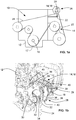
- FIG 1a shows an endless drive arrangement 10 for an engine 12.
- the endless drive arrangement 10 is used to transfer power between the engine 12 and one or more accessories 14.
- the engine 12 has a crankshaft 16, on which there is mounted a crankshaft pulley 17.
- each accessory 14 may have an accessory frame 19, an accessory shaft 20 that is rotatable relative to the accessory frame 19, and an accessory pulley 22 that is mounted on the accessory shaft 20 and is rotatable with the accessory shaft 20 about an accessory pulley axis AAcc.
- the endless drive arrangement 10 includes an endless drive member 24, such as an accessory drive belt, that is drivable by the crankshaft pulley 17, and which, in turn, drives the accessory pulleys 22 of the one or more accessories 14.
- an endless drive member 24 such as an accessory drive belt
- the endless drive member 16 may be referred to as a belt 16.
- any other type of suitable endless drive member may be used.
- a tensioner 26 is provided to maintain tension in the endless drive member 16.
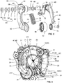
- the tensioner 26 is shown in more detail in Figures 2 and 3 .
- the tensioner 26 includes a tensioner base 28 (which may also simply be referred as the base 28 for convenience), a tensioner arm 30 with a tensioner pulley 32 thereon, and a tensioner biasing member 34.
- the tensioner base 28 is mountable to the accessory frame 19.
- the accessory frame 19 has an end face 36 from which the accessory shaft 20 extends.
- the accessory frame 19 has a plurality of first fastener apertures 38 which may be positioned on mounting ears 77.
- the accessory frame 19 further has an accessory frame body 39 that is generally cylindrical and that has a diameter DAcc.
- the tensioner base 28 includes a plurality of second fastener apertures 40 which are aligned with the plurality of first fastener apertures 38.
- a plurality of base mounting fasteners 41 such as bolts 42 may be used to pass through the apertures 40 and into the apertures 38 to mount the tensioner base 28 to the accessory frame 18.
- the apertures 38 may be threaded to retain the fasteners 41 for this purpose.
- the apertures 38 need not be pass-through apertures, but could be if desirable.
- nuts are used to receive the bolts 42. In such a case the apertures 38 would be pass-through apertures so that the bolts 42 could pass through both the apertures 40 and 38 and into the nuts.
- the tensioner arm 30 is pivotally mounted to the tensioner base 28 for pivotal movement about an arm pivot axis AArm that is offset from the accessory pulley axis AAcc.
- the pivotal connection of the tensioner arm 30 to the tensioner base 28 is provided by means of a hollow shaft member 44 that is press-fit into an aperture 46 ( Figure 4 ) in the tensioner base 28 and which pivotably supports the tensioner arm 30 via a plurality of bushings 48, 50 and 52.
- the bushings 48, 50 and 52 may be made from any suitable materials such as nylon impregnated with PTFE.
- the bushings 48, 50 and 52 may be configured to be fixed to the tensioner arm 30 so that they pivot about the hollow shaft member 44 along with the tensioner arm 30.
- a damping structure 54 may optionally be provided, which includes a first damping member 56 that has a first friction surface 58 thereon that is fixed to the shaft member 44, and which engages a second friction surface 60 that is on an axially outer face of the bushing 52.
- the bushing 52 may additionally be referred to as a second damping member.
- the damping structure 54 may further include a damping structure biasing structure 62 that is positioned to urge the first damping member 56 (and therefore the first friction surface 58) into engagement with the second friction surface 60 with a selected force.
- the damping structure biasing structure 62 may include, for example, a plurality of Belleville washers 64.
- a tensioner arm locking member 66 may be press-fit onto a distal end of the shaft member 44 to lock the tensioner arm 30 on the shaft member 44 and may be positioned to provide a reference surface which the Belleville washers 64 abut so as to urge the friction surfaces 58 and 60 against one another.
- An example of a suitable damping structure 54 is shown in US Patent No. 8,591,358 .
- the tensioner pulley 32 is rotatably mounted to the tensioner arm 30 for rotation about a tensioner pulley axis ATP that is offset relative to the arm pivot axis AArm and relative to the accessory pulley axis AAcc.
- the rotatable mounting to the tensioner arm 30 may be by any suitable means.
- the pulley 32 may include a pulley bearing 68 that mounts to a shoulder bolt 69 that, in turn, mounts to the tensioner arm 30.
- a dust shield 70 is provided to inhibit the migration of dust and other contaminants into the pulley bearing 68.
- the tensioner pulley axis ATP is angularly offset by an offset angle OA that is between about 135 degrees and about 225 degrees along the tensioner arm 30 relative to the arm pivot axis AArm, about the accessory pulley axis AAcc.
- the offset angle may be, for example, about 180 degrees. This offset angle is discussed further below.
- the tensioner biasing member 34 urges the tensioner arm 30 into the belt 30, which is a direction that may be referred to as a 'free arm' direction.
- the tensioner biasing member 34 may be any suitable type of biasing member, such as a compression spring.
- the tensioner biasing member 34 has a first end 71 that engages a first end support surface 72 on the base 28 and a second end 74 that engages a second end support surface 76 on the tensioner arm 30.
- suitable compression springs for the biasing member 34 include a helical compression spring (as shown in Figures 2-4 ), and a closed-cell foam spring.
- the tensioner 26 is arranged such that its mounting to the accessory frame 19 applies relatively small moments and therefore relatively low stresses are incurred by the accessory frame as a result.
- the low stresses are achieved by mounting the tensioner 26 to the accessory frame 19 via a plurality of fasteners (e.g. bolts 42) that are each positioned at a center distance (shown at DC in Figure 3 ) from the accessory pulley axis AAcc that is between a value of zero inches from the accessory pulley axis AAcc to a value that is less than about 25 mm greater than the frame body diameter DAcc.
- the fasteners e.g. bolts 42
- the fasteners are positioned with center distances DC that are between a value of zero inches from the accessory pulley axis AAcc to a value that is less than about 8 mm greater than the frame body diameter DAcc.
- the base 28 is the only part of the tensioner 26 that mounts directly to the accessory frame 19.
- the tensioner biasing member 34 mounts between the base 28 and the tensioner arm 30; the tensioner arm 30 mounts to the base 28; and the tensioner pulley 32 mounts to the arm 30, as noted above. It will be understood, however, that this need not be the case.
- one end of the tensioner biasing member 34 could mount directly to a mounting ear on the alternator frame 19 instead of mounting to the base 28.
- the configuration o ⁇ the tensioner 26 is advantageous in that the components of the tensioner 26 (e.g. such as the base 28, the tensioner biasing member 34 and the tensioner arm 30) do not extend radially significantly beyond frame body diameter DAcc.
- the base 28, the tensioner arm 30 and the tensioner biasing member 34 can typically be mounted to the alternator 28 without interfering with other engine- related components. This is especially useful in vehicles with relatively small engines, which are relatively common currently, since there is sometimes very little space for tensioners on such engines.
- tensioners of the prior art are also configured to fit in a relatively small space radially, but suffer from certain deficiencies.
- such tensioners are 'orbital' tensioners, in the sense that the tensioner pulley is mounted on an arcuate arm that slides on an arcuate path on the base, so that the tensioner pulley follows an arcuate path about the axis of rotation of the alternator pulley.
- Such tensioners can be difficult to control so that they provide consistent performance over the course of their operating life.
- Such tensioners sometimes employ a large torsion spring in order to urge the tensioner pulley into the belt. Such a large torsion spring is needed to clear the alternator pulley, however it is not ideal from a packaging point of view.
- Some other tensioners of the prior art employ biasing members that are more compact than a large, helical torsion spring, but they apply a moment to the tensioner arm at a relatively small moment arm, relative to the moment applied by the hub load on the tensioner arm that arises from engagement of the tensioner pulley with the belt.
- the biasing member in such cases may be made with a relatively high spring rate, which is undesirable from the point of view of providing good isolation and maintaining relatively low belt tension where possible.
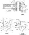
- FIG. 5b Another type of prior art tensioner employs a pivoting arm and is represented in Figure 5b .
- This tensioner employs a tensioner arm (shown at 30old) that pivots about a pivot axis (AArmOld) and has a pulley (shown at 32old) thereon.
- a tensioner biasing member shown at 34old urges the tensioner arm 30old to drive the pulley 32old into the belt 24.
- the biasing member 34old extends out in a manner that would increase the likelihood of interference with other engine-related components and engages the arm 30old at a point where the moment applied by the biasing member 34old is at a relatively short moment arm LSold about the arm pivot axis AArmOld 1 in comparison to the moment arm LHold.
- the biasing member force shown at FSold is generally high. This introduces relatively high bending stresses in the tensioner arm 30old. The bending stresses over the length of the tensioner arm 30old are shown by the curve 80 in Figure 6b .
- the orientation of the biasing member 34old results in its distal end being positioned far from cylindrical surface of the accessory frame to which it is mounted.
- a bracket is formed into accessory frame that extends relatively far from the cylindrical surface of the accessory frame. This introduces significant stresses into the accessory frame which necessitate reinforcing the accessory frame to compensate for them, which can increase the cost of the accessory frame undesirably.
- the present tensioner 26 employs a tensioner arm 30 that pivots and does not 'orbit' and, in at least some arrangements, employs a biasing member (e.g. biasing member 34) that applies a moment on the tensioner arm 30 with a moment arm LS that is at least about 50 percent of the size of the moment arm LH associated with the hub load moment applied by the belt 24 via the tensioner pulley 32, and, in at least some arrangements, mounts to the accessory frame via fasteners (e.g.
- the biasing member 34 may apply a moment on the tensioner 30 with a moment arm LS that is at least about 80 percent of the size of the moment arm LH associated with the hub load moment applied by the belt 24. In some arrangements, the biasing member 34 may apply a moment on the tensioner 30 with a moment arm LS that is substantially equal to the size of the moment arm LH associated with the hub load moment applied by the belt 24.
- Figure 5a is a schematic diagram that represents the forces and moment arms associated with the tensioner shown in Figures 2-4 .
- the moment arm shown at LS is the moment arm of the spring force shown at FS.
- the moment arm LS can be large, (e.g. at least about 50 percent of the moment arm shown at LH, for the hub load shown at FH), which is in direct contrast with the moment arm for the tensioner represented in Figure 5b .
- the endless drive member 24 engages the tensioner pulley 32 and applied a hub load force FH on the tensioner pulley 32.
- the endless drive member 24 applies a hub load moment on the tensioner arm 30, which is based on the hub load force FH and a first moment arm (i.e. moment arm LH) relative to the arm pivot axis AArm.
- the tensioner biasing member 34 applies a biasing member moment on the tensioner arm 30 that opposes the hub load moment, along a second moment arm (i.e. moment arm LS) relative to the arm pivot axis AArm.
- the second moment arm LS may be at least 50 percent of the length of the first moment arm LH. In some arrangements, the second moment arm LS may be at least 80 percent of the length of the first moment arm LH. In some arrangements, the second moment arm LS may be substantially equal to the length of the first moment arm LH.
- the force applied by the biasing member 34 i.e. the force FS
- the force applied by the biasing member 34old i.e. the force FSold
- the bending stress for the tensioner arm 30 over the length of the arm 30 is shown by the curve 82 in Figure 6a .
- the tensioner biasing member 34 is substantially completely superimposed axially with the tensioner arm. In other words, when viewed in an axial direction, the tensioner biasing member 34 is substantially entirely hidden. It will further be noted that, in the arrangement shown in Figure 3 , the tensioner arm is concave about accessory pulley axis AAcc. This concavity, in combination with the large offset angle OA between the arm pivot axis AArm and the tensioner pulley axis ATP of between about 135 degrees and about 225 degrees permits the tensioner biasing member 34 to be arranged so that its distal end (i.e. first end 71) remains relatively close to the accessory pulley axis AAcc (so that the tensioner 26 can mount to the accessory 18 using fasteners with the relatively short center distances described above).
- the tensioner 26 may optionally include a pin 90.
- the pin 90 may mount into an aperture 92 in the base 28 and may be used to provide a limit surface to limit the movement of the tensioner arm 30 in the load stop direction during use.
- the arm 30 can be permitted to pivot in the free-arm direction to engage the belt 24.
- the aperture 92 for receiving the pin 90 is no longer obscured by the arm 30 and can receive the pin 90.
- the pin 90 can be inserted lockingly into the aperture 92 in any suitable way, such as by press-fit, or any other suitable means, and can then act as a load stop for the arm 30.
- the tensioner 100 includes a tensioner base 128 (also referred as the base 128 for convenience) which may be similar to the base 28, a tensioner arm 130 that is similar to the tensioner arm 30, with a tensioner pulley 132 thereon, that is similar to pulley 32, and a tensioner biasing member 134 that is similar to the biasing member 34.
- the tensioner 100 is mountable to the accessory frame 19 via fasteners 141 such as bolts 142 which pass through second apertures 140 in the base 128 and into first apertures 38, in the same manner as the tensioner 26 shown in Figure 1b uses fasteners 42 to mount to the accessory frame 19.
- the apertures 38 on the accessory frame 19 are arranged differently, to accommodate the different arrangement of the tensioner biasing member 134 as compared to the tensioner biasing member 34 in the arrangement shown in Figures 2-4 .
- the tensioner 100 may be similar to the tensioner 26 in several respects.
- the tensioner arm 130 pivots and does not 'orbit' and, in at least some arrangements, the offset angle OA about the accessory pulley axis AAcc, between the tensioner pulley axis ATP ( Figure 8 ) and the arm pivot axis AArm is between about 135 degrees and about 225 degrees along the tensioner arm 30.
- the offset angle may be, for example, about 180 degrees.
- the tensioner arm 130 mounts to the accessory frame via fasteners 141 (e.g.
- the fasteners e.g. bolts 42
- the tensioner biasing member 134 may be a compression spring in similar manner to the biasing member 34 shown in Figures 2-4 .
- An example of a suitable compression spring for the biasing member 134 may be, a helical compression spring, a closed-cell foam spring or any other kind of compression spring.
- the tensioner biasing member 134 has a first end 171 that engages a first end support surface 172 on the base 128 and a second end 174 that engages a second end support surface 176 on the tensioner arm 130.
- a difference between the tensioner 100 and the tensioner 26 is that, as noted above, the biasing member 134 is arranged in a different place in relation to the rest of the tensioner 100, as compared to the biasing member 34 in relation to the rest of the tensioner 26.
- the second end support surface 176 on the tensioner arm 130 is outside of a range between the arm pivot axis AArm and the tensioner pulley axis ATP.
- the tensioner 100 may employ a damping structure 154 that may be similar to the damping structure 54, and bushings 148, 150 and 152 that are provided on a hollow shaft 144, and which are similar to the bushings 48, 50 and 52 and hollow shaft 44.
- the tensioners 26 and 100 may be used on engines which are not part of a hybrid powertrain. As such, an MGU or the like is not provided as a separate means for driving the belt 24. As a result, the belt span on the 'upstream' side of the alternator 18, is normally slack relative to the belt span on the 'downstream' side of the alternator 18, when the engine is driving the belt 24, and remains the slack span of the belt 24 throughout operation of the engine. In arrangements such as those shown in Figures 1a-9 , which may be passive tensioners and which have one arm and one pulley, the tensioner 26 or 100 may be used with non-hybrid powertrains where the engine is always the motive device that drives the belt 24.
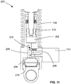
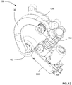
- FIG. 10 and 11 shows the tensioner 100, wherein the biasing member 134 forms part of a tensioner strut shown at 200.
- the tensioner 100 in this instance can be used with a hybrid powertrain, in which the accessory 14 is not an alternator, but is instead an MGU, such that the belt span normally identified as being relatively slack becomes the tighter belt span when the MGU is powered so as to drive the belt 24.
- the tensioner strut 200 is controllable during use to prevent compression of the tensioner strut 200 at any of a plurality of selectable positions.
- the tensioner strut 200 may be hydraulically controlled, and may include a main piston chamber 202, a reservoir 204, and first and second fluid passageways 206 and 208 connecting the main piston chamber 202 and the reservoir 204.
- a main piston 210 is movable in the main piston chamber 202.
- a check valve 212 is positioned to prevent fluid flow in a first fluid flow direction between the main piston chamber 202 and the reservoir 204 through the second passageway 208 and to permit fluid flow in an opposing fluid flow direction between the reservoir 204 and the main piston chamber 202 through the second fluid passageway 208.
- a control valve 214 is positioned in the first fluid passageway 206 and is movable between a first position to provide a first flow resistance through the control valve 214 and a second position (shown in dashed lines) to provide a second flow resistance through the control valve 214.
- the first flow resistance is lower than the second flow resistance.
- a movable reservoir member 216 e.g.
- a compressible air bladder is provided in the reservoir 204 and is movable based on the amount of fluid is in the reservoir 204 in such a way as to change the volume of the reservoir 204, such that the reservoir 204, the main piston chamber 202 and the first and second passageways 206 and 208 together are included in a fluid circuit that contains an incompressible fluid, such as hydraulic oil, and is substantially free of any compressible fluids, such as air.
- an incompressible fluid such as hydraulic oil
- the tensioner biasing member 134 is part of a strut 300, that renders the tensioner 100 suitable for use with a hybrid powertrain, in which the accessory 14 is not an alternator, but is instead an MGU, such that the belt span normally identified as being relatively slack becomes the tighter belt span when the MGU is powered so as to drive the belt 24.
- the strut 300 includes an extensible member 302 that is pivotally connected to one of the tensioner arm 130 and a stationary member (e.g. the base 128), a housing 304 that is pivotally connected to the other of the tensioner arm 130 and a stationary member (e.g. the base 128), an actuator 306 ( Figure 11 ), and an adjustable load-stop member 308.
- the actuator 306 is operatively connected to the adjustable load stop member 308 to drive the adjustable load stop member 308 towards the extensible member 302.
- the strut 300 may be as disclosed in PCT publication No.WO2013/159181A2 , the contents of which are incorporated fully herein by reference.
- the extensible member 302 is slidably disposed in the housing 304.
- the adjustable load stop member 308 can be used to control the depth to which the extensible member 302 can be retracted into the housing 304.
- the load stop member 308 can be adjusted in position by the actuator 306 which is operatively connected to the adjustable load stop member 308 via a load stop drive arrangement 310, to drive the adjustable load stop member 308 towards (and optionally away from) the extensible member 302.
- the adjustable load stop member 308 includes a threaded rod portion 312 that rotatable within a threaded bore 314 to drive the rod 308 longitudinally towards or away from the extensible member 302.
- the drive arrangement 310 may include a plurality of gears, one of which is shaped to rotatably drive the load stop member 308 but permits longitudinal movement of the load stop member 308.
- the actuator 306 may be any suitable type of actuator, such as a bidirectional electric motor.
- the actuator 306 may be made sufficiently strong to drive the adjustable load-stop member 308 into the extensible member 302 with sufficient force to drive the pulley 132 into the belt 24 ( Figure 7 ), against the hub load applied by the belt 24 on the pulley 132, thereby permitting the belt tension to be increased as desired.
- the biasing member 34 could form part of the strut 200 or the strut 300, instead of the biasing member 134.
- tensioners 26 and 100 Another advantage to the tensioners 26 and 100 is that the amount of belt takeup per degree of pivoting of the tensioner arm 30 (or the tensioner arm 130) may be relatively high and may exceed about 2 mm per degree of movement of the arm 30. As a result, relatively little compression of the biasing member 34 (or 134) takes place and therefore relatively little change in the force FS. This can result in a relatively flatter tension/position curve for the tensioner 26 (or 100), which is advantageous in that it can be easier to maintain a relatively uniform tension in the belt 24 over different positions of the tensioner arm 30 (or 130), as compared to some tensioners of the prior art. This can be particularly advantageous for relatively short belts 24 which undergo less stretch over their lifetimes.
- An example of a belt length that the tensioners shown in Figures 1- 13 can be used with is 1200 mm. This belt length corresponds to the length of the belt 24 if the belt were cut at one point and laid out in a line. Other belt lengths are contemplated also, depending on the specific layout of the components of the endless drive arrangement.
- Tensioners 26 and 100 may be advantageous in vehicles where it is desirable to maintain a large hood crush zone (i.e. a large amount of space underneath the hood to ensure that a collision with a pedestrian results in a low likelihood of the pedestrian hitting any 'hard' surfaces under the hood.
- the tensioner shown in Figure 5b would position the distal end of the spring 30old in such a way that it is close to the hood thereby posing a risk of injury to a pedestrian.
- tensioners 26 and 100 have been shown to mount to the end faces of the accessories, it will be understood that they could mount to any portion of the accessory frame 19 or in part to any other suitable stationary member.
Landscapes
- Engineering & Computer Science (AREA)
- General Engineering & Computer Science (AREA)
- Mechanical Engineering (AREA)
- Devices For Conveying Motion By Means Of Endless Flexible Members (AREA)
- Handcart (AREA)
Priority Applications (1)
| Application Number | Priority Date | Filing Date | Title |
|---|---|---|---|
| PL16892945T PL3277979T3 (pl) | 2015-04-02 | 2016-04-04 | Napinacz napędu akcesoriów z ulepszonym układaniem ramienia napinacza i elementu śrubowego |
Applications Claiming Priority (2)
| Application Number | Priority Date | Filing Date | Title |
|---|---|---|---|
| US201562142300P | 2015-04-02 | 2015-04-02 | |
| PCT/CA2016/050388 WO2017152255A1 (en) | 2015-04-02 | 2016-04-04 | Accessory drive tensioner with improved arrangement of tensioner arm and biasing member |
Publications (3)
| Publication Number | Publication Date |
|---|---|
| EP3277979A1 EP3277979A1 (en) | 2018-02-07 |
| EP3277979A4 EP3277979A4 (en) | 2018-08-15 |
| EP3277979B1 true EP3277979B1 (en) | 2021-08-04 |
Family
ID=59788940
Family Applications (1)
| Application Number | Title | Priority Date | Filing Date |
|---|---|---|---|
| EP16892945.3A Active EP3277979B1 (en) | 2015-04-02 | 2016-04-04 | Accessory drive tensioner with improved arrangement of tensioner arm and biasing member |
Country Status (8)
| Country | Link |
|---|---|
| US (1) | US10393238B2 (pl) |
| EP (1) | EP3277979B1 (pl) |
| KR (1) | KR102538859B1 (pl) |
| CN (1) | CN109154366B (pl) |
| ES (1) | ES2893698T3 (pl) |
| HU (1) | HUE056864T2 (pl) |
| PL (1) | PL3277979T3 (pl) |
| WO (1) | WO2017152255A1 (pl) |
Cited By (1)
| Publication number | Priority date | Publication date | Assignee | Title |
|---|---|---|---|---|
| IT202300003939A1 (it) * | 2023-03-03 | 2024-09-03 | Fca Italy Spa | “motore a combustione interna con motogeneratore di tipo bsg e relativo dispositivo tenditore” |
Families Citing this family (4)
| Publication number | Priority date | Publication date | Assignee | Title |
|---|---|---|---|---|
| DE102015215812B4 (de) * | 2015-08-19 | 2020-03-26 | Schaeffler Technologies AG & Co. KG | Riemenspanner |
| WO2020068532A1 (en) * | 2018-09-25 | 2020-04-02 | Borgwarner Inc. | Belt tensioner with a damper that acts on two belt strands |
| KR102552020B1 (ko) * | 2018-10-19 | 2023-07-05 | 현대자동차 주식회사 | 하이브리드 차량용 텐셔너 |
| US20220099165A1 (en) * | 2020-09-28 | 2022-03-31 | Caterpillar Inc. | Engine accessory drive system and one-piece bracket for same |
Family Cites Families (51)
| Publication number | Priority date | Publication date | Assignee | Title |
|---|---|---|---|---|
| DE508156C (de) | 1930-09-24 | Georg Schwabe Maschinenfabrik | Spannrollengetriebe | |
| US976115A (en) * | 1910-11-15 | Burke Electric Company | Power mechanism. | |
| GB773398A (en) * | 1954-10-20 | 1957-04-24 | Stothert & Pitt Ltd | Improvements in and relating to vibratory rollers |
| FR2183356A6 (pl) * | 1972-05-04 | 1973-12-14 | Peugeot & Renault | |
| US4108013A (en) * | 1977-03-28 | 1978-08-22 | Sragal Richard F | Constant tension apparatus for flexible endless drive means |
| US4299583A (en) * | 1979-10-31 | 1981-11-10 | Dyneer Corporation | Hydraulic belt tensioner construction |
| US4500303A (en) * | 1981-12-31 | 1985-02-19 | Cummins Engine Company, Inc. | Idler mechanism |
| US4571223A (en) * | 1984-06-15 | 1986-02-18 | General Motors Corporation | Automatic belt tensioner |
| US4758208A (en) * | 1987-07-13 | 1988-07-19 | General Motors Corporation | Automatic belt tensioner for vehicle combined starter-generator |
| US4822321A (en) * | 1988-07-18 | 1989-04-18 | General Motors Corporation | Combination water pump and belt tensioner |
| DE19631507A1 (de) | 1996-08-03 | 1998-02-05 | Bayerische Motoren Werke Ag | Spannvorrichtung für einen Riementrieb |
| US5938552A (en) * | 1998-06-02 | 1999-08-17 | The Gates Corporation | Tensioner with damping shoe activated by compression spring |
| DE19926615A1 (de) * | 1999-06-11 | 2000-12-14 | Schaeffler Waelzlager Ohg | Spanneinrichtung für Zugmittel wie Riemen oder Ketten |
| DE10146612B4 (de) * | 2001-09-21 | 2016-09-01 | Schaeffler Technologies AG & Co. KG | Spannvorrichtung |
| US7118504B2 (en) * | 2002-02-07 | 2006-10-10 | Dayco Products, Llc | Hydraulic asymmetric damped belt tensioner |
| US6652401B2 (en) * | 2002-02-11 | 2003-11-25 | The Gates Corporation | Method of tuning a belt drive system |
| EP1543256A1 (en) * | 2002-09-20 | 2005-06-22 | The Gates Corporation | Belt tensioner |
| AU2003272594A1 (en) * | 2002-09-20 | 2004-04-08 | The Gates Corporation | Belt tensioner |
| DE60321308D1 (de) * | 2003-04-02 | 2008-07-10 | Bayerische Motoren Werke Ag | Zweiarmiger Riemenspanner |
| US7494434B2 (en) * | 2005-06-15 | 2009-02-24 | Gm Global Technology Operations, Inc. | Belt alternator starter accessory drive with dual tensioner |
| FR2918127B1 (fr) * | 2007-06-29 | 2011-03-18 | Valeo Equip Electr Moteur | Dispositif de demarrage d'un moteur thermique, notamment de vehicule automobile. |
| DE102008025552B4 (de) | 2008-05-28 | 2020-06-10 | Muhr Und Bender Kg | Riemenspannvorrichtung für Starter-Generator-Anwendung |
| US7951030B2 (en) * | 2008-12-04 | 2011-05-31 | The Gates Corporation | Tensioner |
| US8568259B2 (en) * | 2009-09-11 | 2013-10-29 | GM Global Technology Operations LLC | Engine accessory drive with belt tensioner and same plane idler |
| US9133762B2 (en) * | 2009-09-18 | 2015-09-15 | GM Global Technology Operations LLC | Drive belt tensioner for motor generator unit |
| US8602930B2 (en) * | 2009-09-18 | 2013-12-10 | GM Global Technology Operations LLC | Drive belt tensioner for motor generator unit |
| DE102011082764A1 (de) | 2010-10-13 | 2012-04-19 | Schaeffler Technologies Gmbh & Co. Kg | Spannvorrichtung für einen Zugmitteltrieb eines Verbrennungsmotors |
| KR101241209B1 (ko) * | 2011-01-06 | 2013-03-13 | 현대자동차주식회사 | 하이브리드 차량의 벨트 시스템 |
| EP2707625B1 (en) * | 2011-05-13 | 2019-09-25 | Litens Automotive Partnership | Intelligent belt drive system and method |
| DE102011082330B4 (de) | 2011-08-12 | 2014-08-07 | Schaeffler Technologies Gmbh & Co. Kg | Spannvorrichtung für einen Riementrieb und Elektromaschine mit einer derartigen Spannvorrichtung |
| DE102011053869B4 (de) * | 2011-09-22 | 2020-03-26 | Muhr Und Bender Kg | Riemenspannvorrichtung für einen Riementrieb und Aggregatanordnung mit Riemenspannvorrichtung |
| DE102011084680B3 (de) * | 2011-10-18 | 2012-11-22 | Schaeffler Technologies AG & Co. KG | Spannvorrichtung für einen Riementrieb und Elektromaschine mit einer derartigen Spannvorrichtung |
| DE102011088652A1 (de) | 2011-12-15 | 2013-06-20 | Schaeffler Technologies AG & Co. KG | Spannvorrichtung für einen Riementrieb |
| WO2013159181A1 (en) * | 2012-04-28 | 2013-10-31 | Litens Automotive Partnership | Adjustable tensioner |
| DE102012019038A1 (de) | 2012-09-27 | 2014-03-27 | GM Global Technology Operations LLC (n. d. Ges. d. Staates Delaware) | Generator zur Erzeugung von elektrischem Strom in einem Kraftfahrzeug und Kraftfahrzeug |
| DE102012223086A1 (de) | 2012-12-13 | 2014-06-18 | Schaeffler Technologies Gmbh & Co. Kg | Riemenspanner |
| WO2014090417A1 (de) | 2012-12-13 | 2014-06-19 | Schaeffler Technologies AG & Co. KG | Riemenspanner |
| EP3361124B1 (en) * | 2012-12-26 | 2019-10-30 | Litens Automotive Partnership | Orbital tensioner assembly |
| DE102013002993A1 (de) | 2013-02-22 | 2014-08-28 | Schaeffler Technologies Gmbh & Co. Kg | Startergenerator - Riemenspanner |
| DE102013203957B3 (de) * | 2013-03-08 | 2014-02-13 | Schaeffler Technologies AG & Co. KG | Riemenspanner |
| DE102013102562B4 (de) * | 2013-03-13 | 2021-05-27 | Muhr Und Bender Kg | Verwendung einer Feder in einer Riemenspannvorrichtung, Riemenspannvorrichtung und Aggregatanordnung |
| DE102013206010B3 (de) * | 2013-04-05 | 2014-08-07 | Schaeffler Technologies Gmbh & Co. Kg | Riemenspanner |
| DE102013005884A1 (de) | 2013-04-06 | 2014-10-09 | Daimler Ag | Riemenspanner für einen Riementrieb einer Brennkraftmaschine eines Kraftfahrzeugs |
| DE102013206101A1 (de) | 2013-04-08 | 2014-10-30 | Schaeffler Technologies Gmbh & Co. Kg | Lagerring und Dämpfungshülse |
| US9140338B2 (en) * | 2014-02-06 | 2015-09-22 | Gates Corporation | Tensioner |
| US20150300462A1 (en) * | 2014-02-06 | 2015-10-22 | Gates Corporation | Tensioner |
| DE102014206716A1 (de) * | 2014-04-08 | 2015-10-08 | Muhr Und Bender Kg | Riemenspannvorrichtung |
| US20150308545A1 (en) * | 2014-04-28 | 2015-10-29 | The Gates Corporation | Orbital tensioner |
| CN106461034B (zh) * | 2014-06-20 | 2019-08-27 | 利滕斯汽车合伙公司 | 具有液压锁定特征的张紧器 |
| DE102014117094A1 (de) * | 2014-11-21 | 2016-05-25 | Muhr Und Bender Kg | Riemenspannvorrichtung |
| US9651122B2 (en) * | 2015-02-05 | 2017-05-16 | Gates Corporation | Dual arm tensioner |
-
2016
- 2016-04-04 PL PL16892945T patent/PL3277979T3/pl unknown
- 2016-04-04 KR KR1020177031342A patent/KR102538859B1/ko active Active
- 2016-04-04 CN CN201680020763.XA patent/CN109154366B/zh active Active
- 2016-04-04 HU HUE16892945A patent/HUE056864T2/hu unknown
- 2016-04-04 EP EP16892945.3A patent/EP3277979B1/en active Active
- 2016-04-04 ES ES16892945T patent/ES2893698T3/es active Active
- 2016-04-04 WO PCT/CA2016/050388 patent/WO2017152255A1/en not_active Ceased
- 2016-04-04 US US15/563,769 patent/US10393238B2/en active Active
Non-Patent Citations (1)
| Title |
|---|
| None * |
Cited By (1)
| Publication number | Priority date | Publication date | Assignee | Title |
|---|---|---|---|---|
| IT202300003939A1 (it) * | 2023-03-03 | 2024-09-03 | Fca Italy Spa | “motore a combustione interna con motogeneratore di tipo bsg e relativo dispositivo tenditore” |
Also Published As
| Publication number | Publication date |
|---|---|
| PL3277979T3 (pl) | 2022-01-10 |
| KR20170134551A (ko) | 2017-12-06 |
| CN109154366B (zh) | 2021-10-15 |
| EP3277979A4 (en) | 2018-08-15 |
| US10393238B2 (en) | 2019-08-27 |
| HUE056864T2 (hu) | 2022-03-28 |
| WO2017152255A8 (en) | 2017-10-19 |
| WO2017152255A1 (en) | 2017-09-14 |
| ES2893698T3 (es) | 2022-02-09 |
| US20180066733A1 (en) | 2018-03-08 |
| KR102538859B1 (ko) | 2023-06-01 |
| CN109154366A (zh) | 2019-01-04 |
| EP3277979A1 (en) | 2018-02-07 |
Similar Documents
| Publication | Publication Date | Title |
|---|---|---|
| EP3277979B1 (en) | Accessory drive tensioner with improved arrangement of tensioner arm and biasing member | |
| EP3209901B1 (en) | Endless drive arrangement and improved two-armed tensioning system for same | |
| EP2831468B1 (en) | Tensioner and endless drive arrangement | |
| EP2938905B1 (en) | Orbital tensioner assembly | |
| EP3253996B1 (en) | Endless drive arrangement for hybrid vehicle using two-armed tensioner with non-orbiting arms | |
| US9599199B2 (en) | Tensioner with multiple spring rates | |
| EP3161346B2 (en) | Orbital tensioner assembly | |
| AU2014392605B2 (en) | Orbital tensioner | |
| DE102010034955B4 (de) | Antriebsriemenspanneranordnung, Nebenaggregatantrieb für eine Maschine sowie Maschinensystem mit einem Riemen-Lichtmaschine-Anlasser-Nebenaggregat-Antriebssystem | |
| US11041549B2 (en) | Tensioning device | |
| DE102010045340A1 (de) | Antriebsriemenspanner für eine Motor/Generator-Einheit | |
| EP2988021B1 (en) | Accessory mounts for tensioning systems | |
| US20200132173A1 (en) | Tensioner | |
| DE202017104860U1 (de) | Spannvorrichtungs-Anordnung mit Riemenscheiben-Einstellstruktur |
Legal Events
| Date | Code | Title | Description |
|---|---|---|---|
| STAA | Information on the status of an ep patent application or granted ep patent |
Free format text: STATUS: THE INTERNATIONAL PUBLICATION HAS BEEN MADE |
|
| PUAI | Public reference made under article 153(3) epc to a published international application that has entered the european phase |
Free format text: ORIGINAL CODE: 0009012 |
|
| STAA | Information on the status of an ep patent application or granted ep patent |
Free format text: STATUS: REQUEST FOR EXAMINATION WAS MADE |
|
| 17P | Request for examination filed |
Effective date: 20170928 |
|
| AK | Designated contracting states |
Kind code of ref document: A1 Designated state(s): AL AT BE BG CH CY CZ DE DK EE ES FI FR GB GR HR HU IE IS IT LI LT LU LV MC MK MT NL NO PL PT RO RS SE SI SK SM TR |
|
| AX | Request for extension of the european patent |
Extension state: BA ME |
|
| A4 | Supplementary search report drawn up and despatched |
Effective date: 20180718 |
|
| RIC1 | Information provided on ipc code assigned before grant |
Ipc: B60K 25/02 20060101ALI20180712BHEP Ipc: F16H 7/12 20060101AFI20180712BHEP |
|
| DAV | Request for validation of the european patent (deleted) | ||
| DAX | Request for extension of the european patent (deleted) | ||
| STAA | Information on the status of an ep patent application or granted ep patent |
Free format text: STATUS: EXAMINATION IS IN PROGRESS |
|
| 17Q | First examination report despatched |
Effective date: 20190514 |
|
| GRAP | Despatch of communication of intention to grant a patent |
Free format text: ORIGINAL CODE: EPIDOSNIGR1 |
|
| STAA | Information on the status of an ep patent application or granted ep patent |
Free format text: STATUS: GRANT OF PATENT IS INTENDED |
|
| INTG | Intention to grant announced |
Effective date: 20210305 |
|
| GRAS | Grant fee paid |
Free format text: ORIGINAL CODE: EPIDOSNIGR3 |
|
| GRAA | (expected) grant |
Free format text: ORIGINAL CODE: 0009210 |
|
| STAA | Information on the status of an ep patent application or granted ep patent |
Free format text: STATUS: THE PATENT HAS BEEN GRANTED |
|
| AK | Designated contracting states |
Kind code of ref document: B1 Designated state(s): AL AT BE BG CH CY CZ DE DK EE ES FI FR GB GR HR HU IE IS IT LI LT LU LV MC MK MT NL NO PL PT RO RS SE SI SK SM TR |
|
| REG | Reference to a national code |
Ref country code: GB Ref legal event code: FG4D |
|
| REG | Reference to a national code |
Ref country code: AT Ref legal event code: REF Ref document number: 1417284 Country of ref document: AT Kind code of ref document: T Effective date: 20210815 |
|
| REG | Reference to a national code |
Ref country code: CH Ref legal event code: EP |
|
| REG | Reference to a national code |
Ref country code: DE Ref legal event code: R096 Ref document number: 602016061808 Country of ref document: DE |
|
| REG | Reference to a national code |
Ref country code: IE Ref legal event code: FG4D |
|
| REG | Reference to a national code |
Ref country code: RO Ref legal event code: EPE |
|
| REG | Reference to a national code |
Ref country code: LT Ref legal event code: MG9D |
|
| REG | Reference to a national code |
Ref country code: NL Ref legal event code: MP Effective date: 20210804 |
|
| PG25 | Lapsed in a contracting state [announced via postgrant information from national office to epo] |
Ref country code: LT Free format text: LAPSE BECAUSE OF FAILURE TO SUBMIT A TRANSLATION OF THE DESCRIPTION OR TO PAY THE FEE WITHIN THE PRESCRIBED TIME-LIMIT Effective date: 20210804 Ref country code: BG Free format text: LAPSE BECAUSE OF FAILURE TO SUBMIT A TRANSLATION OF THE DESCRIPTION OR TO PAY THE FEE WITHIN THE PRESCRIBED TIME-LIMIT Effective date: 20211104 Ref country code: PT Free format text: LAPSE BECAUSE OF FAILURE TO SUBMIT A TRANSLATION OF THE DESCRIPTION OR TO PAY THE FEE WITHIN THE PRESCRIBED TIME-LIMIT Effective date: 20211206 Ref country code: NO Free format text: LAPSE BECAUSE OF FAILURE TO SUBMIT A TRANSLATION OF THE DESCRIPTION OR TO PAY THE FEE WITHIN THE PRESCRIBED TIME-LIMIT Effective date: 20211104 Ref country code: HR Free format text: LAPSE BECAUSE OF FAILURE TO SUBMIT A TRANSLATION OF THE DESCRIPTION OR TO PAY THE FEE WITHIN THE PRESCRIBED TIME-LIMIT Effective date: 20210804 Ref country code: FI Free format text: LAPSE BECAUSE OF FAILURE TO SUBMIT A TRANSLATION OF THE DESCRIPTION OR TO PAY THE FEE WITHIN THE PRESCRIBED TIME-LIMIT Effective date: 20210804 Ref country code: SE Free format text: LAPSE BECAUSE OF FAILURE TO SUBMIT A TRANSLATION OF THE DESCRIPTION OR TO PAY THE FEE WITHIN THE PRESCRIBED TIME-LIMIT Effective date: 20210804 Ref country code: RS Free format text: LAPSE BECAUSE OF FAILURE TO SUBMIT A TRANSLATION OF THE DESCRIPTION OR TO PAY THE FEE WITHIN THE PRESCRIBED TIME-LIMIT Effective date: 20210804 |
|
| REG | Reference to a national code |
Ref country code: ES Ref legal event code: FG2A Ref document number: 2893698 Country of ref document: ES Kind code of ref document: T3 Effective date: 20220209 |
|
| PG25 | Lapsed in a contracting state [announced via postgrant information from national office to epo] |
Ref country code: LV Free format text: LAPSE BECAUSE OF FAILURE TO SUBMIT A TRANSLATION OF THE DESCRIPTION OR TO PAY THE FEE WITHIN THE PRESCRIBED TIME-LIMIT Effective date: 20210804 Ref country code: GR Free format text: LAPSE BECAUSE OF FAILURE TO SUBMIT A TRANSLATION OF THE DESCRIPTION OR TO PAY THE FEE WITHIN THE PRESCRIBED TIME-LIMIT Effective date: 20211105 |
|
| REG | Reference to a national code |
Ref country code: HU Ref legal event code: AG4A Ref document number: E056864 Country of ref document: HU |
|
| PG25 | Lapsed in a contracting state [announced via postgrant information from national office to epo] |
Ref country code: NL Free format text: LAPSE BECAUSE OF FAILURE TO SUBMIT A TRANSLATION OF THE DESCRIPTION OR TO PAY THE FEE WITHIN THE PRESCRIBED TIME-LIMIT Effective date: 20210804 |
|
| PG25 | Lapsed in a contracting state [announced via postgrant information from national office to epo] |
Ref country code: DK Free format text: LAPSE BECAUSE OF FAILURE TO SUBMIT A TRANSLATION OF THE DESCRIPTION OR TO PAY THE FEE WITHIN THE PRESCRIBED TIME-LIMIT Effective date: 20210804 |
|
| REG | Reference to a national code |
Ref country code: DE Ref legal event code: R097 Ref document number: 602016061808 Country of ref document: DE |
|
| PG25 | Lapsed in a contracting state [announced via postgrant information from national office to epo] |
Ref country code: SM Free format text: LAPSE BECAUSE OF FAILURE TO SUBMIT A TRANSLATION OF THE DESCRIPTION OR TO PAY THE FEE WITHIN THE PRESCRIBED TIME-LIMIT Effective date: 20210804 Ref country code: SK Free format text: LAPSE BECAUSE OF FAILURE TO SUBMIT A TRANSLATION OF THE DESCRIPTION OR TO PAY THE FEE WITHIN THE PRESCRIBED TIME-LIMIT Effective date: 20210804 Ref country code: EE Free format text: LAPSE BECAUSE OF FAILURE TO SUBMIT A TRANSLATION OF THE DESCRIPTION OR TO PAY THE FEE WITHIN THE PRESCRIBED TIME-LIMIT Effective date: 20210804 Ref country code: CZ Free format text: LAPSE BECAUSE OF FAILURE TO SUBMIT A TRANSLATION OF THE DESCRIPTION OR TO PAY THE FEE WITHIN THE PRESCRIBED TIME-LIMIT Effective date: 20210804 Ref country code: AL Free format text: LAPSE BECAUSE OF FAILURE TO SUBMIT A TRANSLATION OF THE DESCRIPTION OR TO PAY THE FEE WITHIN THE PRESCRIBED TIME-LIMIT Effective date: 20210804 |
|
| PLBE | No opposition filed within time limit |
Free format text: ORIGINAL CODE: 0009261 |
|
| STAA | Information on the status of an ep patent application or granted ep patent |
Free format text: STATUS: NO OPPOSITION FILED WITHIN TIME LIMIT |
|
| 26N | No opposition filed |
Effective date: 20220506 |
|
| PG25 | Lapsed in a contracting state [announced via postgrant information from national office to epo] |
Ref country code: SI Free format text: LAPSE BECAUSE OF FAILURE TO SUBMIT A TRANSLATION OF THE DESCRIPTION OR TO PAY THE FEE WITHIN THE PRESCRIBED TIME-LIMIT Effective date: 20210804 |
|
| REG | Reference to a national code |
Ref country code: AT Ref legal event code: UEP Ref document number: 1417284 Country of ref document: AT Kind code of ref document: T Effective date: 20210804 |
|
| REG | Reference to a national code |
Ref country code: CH Ref legal event code: PL |
|
| REG | Reference to a national code |
Ref country code: BE Ref legal event code: MM Effective date: 20220430 |
|
| PG25 | Lapsed in a contracting state [announced via postgrant information from national office to epo] |
Ref country code: MC Free format text: LAPSE BECAUSE OF FAILURE TO SUBMIT A TRANSLATION OF THE DESCRIPTION OR TO PAY THE FEE WITHIN THE PRESCRIBED TIME-LIMIT Effective date: 20210804 Ref country code: LU Free format text: LAPSE BECAUSE OF NON-PAYMENT OF DUE FEES Effective date: 20220404 Ref country code: LI Free format text: LAPSE BECAUSE OF NON-PAYMENT OF DUE FEES Effective date: 20220430 Ref country code: CH Free format text: LAPSE BECAUSE OF NON-PAYMENT OF DUE FEES Effective date: 20220430 |
|
| PG25 | Lapsed in a contracting state [announced via postgrant information from national office to epo] |
Ref country code: BE Free format text: LAPSE BECAUSE OF NON-PAYMENT OF DUE FEES Effective date: 20220430 |
|
| PG25 | Lapsed in a contracting state [announced via postgrant information from national office to epo] |
Ref country code: IE Free format text: LAPSE BECAUSE OF NON-PAYMENT OF DUE FEES Effective date: 20220404 |
|
| P01 | Opt-out of the competence of the unified patent court (upc) registered |
Effective date: 20230530 |
|
| PG25 | Lapsed in a contracting state [announced via postgrant information from national office to epo] |
Ref country code: MK Free format text: LAPSE BECAUSE OF FAILURE TO SUBMIT A TRANSLATION OF THE DESCRIPTION OR TO PAY THE FEE WITHIN THE PRESCRIBED TIME-LIMIT Effective date: 20210804 Ref country code: CY Free format text: LAPSE BECAUSE OF FAILURE TO SUBMIT A TRANSLATION OF THE DESCRIPTION OR TO PAY THE FEE WITHIN THE PRESCRIBED TIME-LIMIT Effective date: 20210804 |
|
| PG25 | Lapsed in a contracting state [announced via postgrant information from national office to epo] |
Ref country code: MT Free format text: LAPSE BECAUSE OF FAILURE TO SUBMIT A TRANSLATION OF THE DESCRIPTION OR TO PAY THE FEE WITHIN THE PRESCRIBED TIME-LIMIT Effective date: 20210804 |
|
| PGFP | Annual fee paid to national office [announced via postgrant information from national office to epo] |
Ref country code: RO Payment date: 20250327 Year of fee payment: 10 |
|
| PGFP | Annual fee paid to national office [announced via postgrant information from national office to epo] |
Ref country code: PL Payment date: 20250313 Year of fee payment: 10 Ref country code: FR Payment date: 20250310 Year of fee payment: 10 |
|
| PGFP | Annual fee paid to national office [announced via postgrant information from national office to epo] |
Ref country code: GB Payment date: 20250306 Year of fee payment: 10 Ref country code: IT Payment date: 20250320 Year of fee payment: 10 |
|
| PGFP | Annual fee paid to national office [announced via postgrant information from national office to epo] |
Ref country code: DE Payment date: 20250305 Year of fee payment: 10 |
|
| PGFP | Annual fee paid to national office [announced via postgrant information from national office to epo] |
Ref country code: ES Payment date: 20250506 Year of fee payment: 10 |
|
| PGFP | Annual fee paid to national office [announced via postgrant information from national office to epo] |
Ref country code: HU Payment date: 20250327 Year of fee payment: 10 |
|
| PGFP | Annual fee paid to national office [announced via postgrant information from national office to epo] |
Ref country code: AT Payment date: 20250325 Year of fee payment: 10 |
|
| PG25 | Lapsed in a contracting state [announced via postgrant information from national office to epo] |
Ref country code: TR Free format text: LAPSE BECAUSE OF FAILURE TO SUBMIT A TRANSLATION OF THE DESCRIPTION OR TO PAY THE FEE WITHIN THE PRESCRIBED TIME-LIMIT Effective date: 20210804 |