EP3277869B1 - Élément de renfort hybride à torsions différenciées - Google Patents
Élément de renfort hybride à torsions différenciées Download PDFInfo
- Publication number
- EP3277869B1 EP3277869B1 EP16714818.8A EP16714818A EP3277869B1 EP 3277869 B1 EP3277869 B1 EP 3277869B1 EP 16714818 A EP16714818 A EP 16714818A EP 3277869 B1 EP3277869 B1 EP 3277869B1
- Authority
- EP
- European Patent Office
- Prior art keywords
- twist
- strand
- modulus
- reinforcing element
- tex
- Prior art date
- Legal status (The legal status is an assumption and is not a legal conclusion. Google has not performed a legal analysis and makes no representation as to the accuracy of the status listed.)
- Active
Links
Images

Classifications
-
- B—PERFORMING OPERATIONS; TRANSPORTING
- B60—VEHICLES IN GENERAL
- B60C—VEHICLE TYRES; TYRE INFLATION; TYRE CHANGING; CONNECTING VALVES TO INFLATABLE ELASTIC BODIES IN GENERAL; DEVICES OR ARRANGEMENTS RELATED TO TYRES
- B60C9/00—Reinforcements or ply arrangement of pneumatic tyres
- B60C9/005—Reinforcements made of different materials, e.g. hybrid or composite cords
-
- D—TEXTILES; PAPER
- D02—YARNS; MECHANICAL FINISHING OF YARNS OR ROPES; WARPING OR BEAMING
- D02G—CRIMPING OR CURLING FIBRES, FILAMENTS, THREADS, OR YARNS; YARNS OR THREADS
- D02G3/00—Yarns or threads, e.g. fancy yarns; Processes or apparatus for the production thereof, not otherwise provided for
- D02G3/44—Yarns or threads characterised by the purpose for which they are designed
- D02G3/48—Tyre cords
Definitions
- the invention relates to a reinforcing element, a tire, a semi-finished product and a method of manufacturing such a reinforcing element.
- Textile reinforcing elements made from monofilaments or continuous textile fibers such as polyester, nylon, cellulose or aramid fibers, play an important role in tires, including high performance tires approved to run at very high speed. speed. To meet the requirements of tires, the reinforcing elements must have a high tensile strength, a high modulus in extension, excellent fatigue endurance and finally good adhesion to rubber matrices or other polymers which they are likely to reinforce. .
- Reinforcing elements consisting of two multifilament strands each consisting of elementary textile monofilaments are known from the state of the art.
- the two strands of monofilament are wound around each other by twisting to form a twist.
- Each strand comprising the textile monofilaments is generally referred to as a yarn or overworts depending on the stage of the manufacturing process.
- the role of twisting is to adapt the properties of the material in order to create the transverse cohesion of the reinforcing element, to increase its resistance to fatigue and also to improve the adhesion with the reinforced matrix.
- the endurance or resistance to fatigue (in extension, bending, compression) and the breaking force of these reinforcing elements are essential.
- the endurance is all the higher as the torsions used are important, but that in return, the tensile strength in extension (called toughness when it is reduced to the unit of weight) inexorably decreases when the torsion increases, which of course is penalizing from the point of view of reinforcement.
- the reinforcing element according to the invention has an equivalent breaking force and an improved endurance compared to those of a balanced reinforcing element.
- the increase in the torsion R3 makes it possible to increase the endurance but to the detriment of the breaking force.
- the loss of breaking force linked to the increase in torsion R3 is compensated by the residual torsion R1 strictly greater than the residual torsion R2 as demonstrated by the results of the tests. comparisons described below.
- substantially zero residual torsion is meant that the residual torsion is strictly less than 2.5% of the torsion R3.
- substantially non-zero residual torsion is meant that the residual torsion is greater than or equal to 2.5% of the torsion R3.
- high modulus textile monofilament strand is meant a strand having a so-called final modulus strictly greater than 25 cN / tex.
- strand of low modulus textile monofilaments is meant a strand having a so-called final modulus less than or equal to 25 cN / tex.
- This definition applies both to unbleached strands, that is to say without glue, as to glued strands, that is to say covered with a layer of glue. In the case of glued strands, this definition applies equally well to strands resulting directly from manufacture and to strands resulting from reinforcing elements, whether they come directly from manufacture or extracted from a semi-finished product or from a tire. .
- the final modulus is measured from a force-elongation curve obtained at 20 ° C in a known manner using an “INSTRON” tensile machine fitted with “4D” type clamps (for lower breaking force. at 100 daN) or "4E” (for breaking force at least equal to 100 daN).
- the strand tested undergoes traction over an initial length of 400 mm for the 4D clamps and 800 mm for the 4E clamps, at a nominal speed of 200 mm / min. All results given are an average of 10 measurements.
- protective torsion Prior to the tensile strength of the measured strand, a preliminary torsion, known as "protective torsion", equal to 100 turns per meter, with the exception of aramid strands and whose titer is greater than or equal to 330 tex and for which the pre-twist is equal to 80 turns per meter.
- the final modulus is defined as the slope at the point corresponding to 80% of the breaking force of the force-elongation curve divided by the count of the strand.
- the final modulus is defined as the slope between two points A and B of the force-elongation curve divided by the title of the strand, point A corresponding to 40% of the force at break of the strand and point B corresponding to 60% of the force at break of the strand.
- the titer (or linear density) of the strand is determined according to standard ASTM D1423.
- the titer is given in tex (weight in grams of 1000 m 3 of product - reminder: 0.111 tex equal to 1 denier).
- Each strand of textile monofilaments comprises a plurality of elementary textile monofilaments, optionally intermingled with one another.
- Each strand contains between 50 and 2000 monofilaments.
- each residual twist R1, R2 is determined by untwisting the reinforcing element, which makes it possible to obtain R3, then untwisting each strand, which makes it possible to obtain R1 and R2.
- Each torsion R1, R2, R3 is determined in accordance with the ASTM D 885 / D 885MA standard of January 2010 (paragraph 30), for example using a torsiometer.
- the invention makes it possible to significantly improve the breaking force while maintaining an endurance equivalent to that of a balanced reinforcing element having a torsion R3 identical to the 'invention.
- the invention makes it possible to significantly improve endurance while maintaining a breaking force equivalent to that of a balanced reinforcing element having a lower torsion R3. to the invention.
- the final modulus of the high modulus textile monofilament strand is greater than or equal to 30 cN / tex, preferably 35 cN / tex and more preferably 40 cN / tex.
- the final modulus of the strand of low modulus textile monofilaments is less than or equal to 20 cN / tex, preferably 15 cN / tex and more preferably 10 cN / tex.
- the ratio of the final modulus of the strand of high modulus textile monofilaments to the final modulus of the strand of low modulus textile monofilaments is greater than or equal to 2, preferably 5 and more preferably 7. In the advantageous embodiments of the invention, this ratio is less than or equal to 15 and preferably 10.
- the term “textile or textile material” is understood to mean very generally, any material in a material other than metallic, whether natural or synthetic, capable of being transformed into yarn, fiber or film by any suitable transformation process. Mention may be made, for example, without the examples below being limiting, of a polymer spinning process such as, for example, melt spinning, solution spinning or gel spinning.
- non-polymeric material for example in mineral material such as glass or in non-polymeric organic material such as carbon
- the invention is preferably implemented with materials made of material.
- polymeric both of the thermoplastic type and of the non-thermoplastic type.
- polymeric materials of the thermoplastic or non-thermoplastic type
- celluloses in particular rayon, polyvinyl alcohols (abbreviated “PVA”), polyketones, aramids (aromatic polyamides), aromatic polyesters.
- PBO polybenzazoles
- polyimides polyimides
- polyesters in particular those chosen from PET (polyethylene terephthalate), PEN (polyethylene naphthalate), PBT (polybutylene terephthalate), PBN (polybutylene naphthalate), PPT (polypropylene terephthalate) , PPN (polypropylene naphthalate).
- the directions D1 and D2 are identical.
- the directions D1, D2 and D3 are identical in the case where R2 is substantially non-zero and the directions D1 and D3 are identical in the case where R2 is substantially zero.
- the twists R1 'and R2' to be applied to each strand are reduced to what is strictly necessary.
- the residual twists R1 and R2 come from the total consumption of the twists R1 'and R2' by the final twist R3 unlike a method in which the twists R1 'and R2' would be greater (or equal ) to R3 and in which the residual twists R1 and R2 would come from the surplus of twists R1 'and R2'.
- the high modulus textile monofilaments are made from aromatic polyamide, preferably from aramid.
- aramid monofilament By aramid monofilament, it is recalled in a well-known manner that it is a monofilament of linear macromolecules formed of aromatic groups linked together by amide bonds of which at least 85% are directly linked to two aromatic rings, and more particularly of fibers in poly (p-phenylene terephthalamide) (or PPTA), manufactured for a very long time from optically anisotropic spinning compositions.
- the low modulus monofilaments are of a material selected from celluloses, polyvinyl alcohols, polyketones, aliphatic polyamides, polyesters, polybenzazoles, polyimides and monofilament mixtures of these materials, from preferably selected from aliphatic polyamides, polyesters and monofilament blends of these materials.
- polyester monofilament By polyester monofilament, it is recalled in a well-known manner that it is a monofilament of linear macromolecules formed from groups linked together by ester bonds. Polyesters are produced by polycondensation by esterification between a dicarboxylic acid, or one of its derivatives, and a diol. For example, polyethylene terephthalate can be made by polycondensation of terephthalic acid and ethylene glycol.
- nylon monofilament it is recalled in a well-known manner that it is a monofilament of macromolecules obtained from a synthetic polyamide chain in which the amide bonds are linked directly to one or more aliphatic or cyclo-aliphatic groups.
- An example of nylon is poly (hexamethylene adipamide).
- the torsions can be measured and expressed in two different ways, either and in a simple manner in number of turns per meter (t / m), or, which is more rigorous when wishes to compare materials of different natures (densities) and / or titers, in helix angle of monofilaments or what is equivalent in the form of a torsion factor K.
- the twist R3 ranges from 200 to 450 turns per meter, preferably 250 to 400 turns per meter.
- the R3 torsion controls the endurance of the reinforcing element. Thus, depending on the desired endurance, the appropriate torsion R3 can be chosen. The higher the R3 twist, the better the endurance. Thus, we will more preferably choose a torsion R3 ranging from 280 to 400 turns per meter.
- the reinforcing element has a torsion factor ranging from 130 to 200, preferably from 140 to 190.
- a torsion factor makes it possible to obtain a reinforcing element which is durable and exhibits a high breaking force and in which the twist and strand counts are compatible with high production rates.
- R1 ranges from 10 to 150 turns per meter, preferably from 20 to 120 turns per meter and more preferably from 50 to 110 turns per meter.
- R1 ranges from 10 to 150 turns per meter, preferably from 20 to 120 turns per meter and more preferably from 50 to 110 turns per meter.
- a modulus of the reinforcing element that is too high would be obtained, in particular at low elongations, which would lead to problems during the tire manufacturing process.
- a too low residual torsion R1 does not make it possible to compensate for the loss of breaking force resulting from the torsion R3 providing endurance.
- R2 ranges from 10 to 100 turns per meter, preferably from 15 to 75 turns per meter and more preferably from 20 to 60 turns per meter.
- the ratio R1 / R3 ranges from 0.05 to 0.45, preferably from 0.10 to 0.40, preferably from 0.13 to 0.40, more preferably from 0.13 to 0.36 and even more preferably from 0.20 to 0.35. Such ratios R1 / R3 make it possible to obtain, for a given torsion R3, good endurance of the reinforcing element and a satisfactory breaking force, while maintaining sufficient elongation at break not to induce problems during the process. of manufacturing the tire, in particular during the shaping of the tire.
- the product R1.R3 is greater than or equal to 3000, preferably to 15000, preferably to 30,000 and even more preferably to 44,000.
- the product R1.R3 is less than or equal to 48000. By limiting the value of the product R1.R3 to 48000, the risks of industrial variability of the breaking force are reduced.
- the ratio R3 / R2 and R3 verify R3 / R2 ranges from 0.10 to 10.50 and R3 ranges from 200 to 450 revolutions per meter, preferably R3 / R2 ranges from 2.00 to 8.25 and R3 ranges from from 250 to 400 turns per meter, preferably R3 / R2 ranges from 2.00 to 7.10 and R3 ranges from 280 to 400 turns per meter. Even more preferably, R3 / R2 and R3 verify that R3 / R2 ranges from 3.20 to 8.75 and R3 ranges from 235 to 375 turns per meter. In the intervals R3 / R2 and for the values R3 described above, the compromise breaking force / endurance is improved.
- the ratio R1 / R2 ranges from 1.90 to 10.00, preferably from 1.90 to 5.00 and more preferably from 1.90 to 2.50.
- the titre T1 of the strand of high modulus textile monofilaments ranges from 90 to 400 tex, preferably from 100 to 350 tex and more preferably from 140 to 210 tex.
- the T2 titre of the strand of low modulus textile monofilaments ranges from 80 to 350 tex, preferably from 90 to 290 tex and more preferably from 120 to 190 tex, limits included.
- T1 and T2 are compatible with use in pneumatics. Lower titers would not have sufficient breaking strength while higher titers would lead to reinforcing elements that are too large and difficult to use in tires.
- the breaking force of the reinforcing element is greater than or equal to 30 daN, preferably greater than or equal to 35 daN.
- the breaking force measured according to the ASTM D 885 / D 885MA standard of January 2010, can also be determined from unbleached reinforcing elements, that is to say without glue as from glued reinforcing elements, that is, covered with a layer of glue. In the case of glued reinforcing elements, the determination can be carried out equally well both with the reinforcing elements resulting directly from manufacture and with the reinforcing elements extracted from a semi-finished product or from a tire.
- Another subject of the invention is a semi-finished product comprising a reinforcing element as defined above embedded in an elastomer matrix.
- An example of a semi-finished product in accordance with the invention is a sheet of reinforcing elements comprising the reinforcing elements embedded in an elastomer matrix formed by calendering the reinforcing elements between two bands of elastomer.
- a subject of the invention is also a tire comprising at least one reinforcing element as defined above.
- the tires of the invention in particular, can be intended for motor vehicles of the tourism, 4x4, “SUV” (Sport Utility Vehicles) type, but also for two-wheeled vehicles such as motorcycles, or for industrial vehicles. chosen from vans, "Heavy goods vehicles” - ie, metro, bus, road transport vehicles (trucks, tractors, trailers), off-road vehicles -, agricultural or civil engineering machinery, other transport or handling vehicles .
- SUV Sport Utility Vehicles
- the tires can be intended for motor vehicles of the tourism, 4x4, “SUV” (Sport Utility Vehicles) type.
- the tire comprising two beads each comprising at least one annular reinforcement structure and a carcass reinforcement anchored in each of the beads by an upturn around the annular reinforcement structure, the carcass reinforcement comprises at least one reinforcing element as defined above.
- the tire comprising two beads each comprising at least one annular reinforcement structure and a carcass reinforcement anchored in each of the beads by an upturn around the annular reinforcement structure, the tire comprising a crown reinforcement arranged radially outside the carcass reinforcement, the crown reinforcement comprising a working reinforcement and a hooping reinforcement arranged radially outside the working reinforcement, the hooping reinforcement comprises at least one reinforcing element as defined herein -above.
- the hooping ply comprises the textile hooping reinforcement elements as defined above and substantially parallel to one another.
- Such hoop reinforcement elements form an angle at most equal to 10 °, preferably ranging from 5 ° to 10 ° with the circumferential direction of the tire.
- the tire comprising two beads each comprising at least one annular reinforcing structure and a carcass reinforcement anchored in each of the beads by an upturn around of the annular reinforcement structure, the tire comprising a sidewall reinforcement, the sidewall reinforcement comprises at least one reinforcement element as defined above.
- the tire is suitable for running flat.
- RMG Inflated Driving Mode
- the invention is particularly advantageous in the case of a reinforcing element in which the high modulus strand consists of aramid monofilaments and the low modulus strand consists of polyester monofilament.
- the reinforcing element has a relatively low modulus at low deformations (in normal rolling mode), in this case that of polyester, which proves to be sufficient to ensure RMG performance.
- the reinforcing element has a relatively high to strong deformations (in run-flat mode), in this case that of aramid, which is sufficient to ensure, by itself, the RME performance.
- Such a tire suitable for run flat preferably comprises a sidewall insert disposed axially inside the carcass reinforcement.
- the carcass reinforcement comprises a single carcass ply.
- R1 ' ⁇ R2'.
- R1 ' ⁇ R3.
- D1 'and D2' are identical.
- D3 is opposite to D1 'and D2'.
- the expression refers to a radius of the tire. It is in this sense that we say from point A that it is “radially interior” to point B (or “radially inside” point B) if it is closer to the axis. of rotation of the tire than point B. Conversely, a point C is said to be “radially outside” a point D (or “radially outside” of point D) if it is further from the axis of rotation of the tire. tire than point D.
- a reinforcing element or a frame is said to be "radial" when the reinforcing element or the reinforcing elements of the frame form with the circumferential direction an angle greater than or equal to 65 ° and less than or equal to 90 ° .
- radial section or “radial section” is meant here a section or a section along a plane which includes the axis of rotation of the tire.
- An “axial” direction is a direction parallel to the axis of rotation of the tire.
- a point E is said to be “axially inside” at a point F (or “axially inside” of point F) if it is closer to the median plane of the tire than point F.
- a point G is said to be “ axially outside “an H point (or” axially outside “of the H point) if it is further from the median plane of the tire than the H point.
- the “median plane” of the tire is the plane which is normal to the axis of rotation of the tire and which is located equidistant from the annular reinforcing structures of each bead.
- a “circumferential” direction is a direction which is perpendicular both to a radius of the tire and to the axial direction.
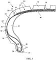
- the tire 10 is of the run-flat type.
- the tire 10 is for a passenger vehicle.
- This tire 10 comprises a crown 12 comprising a crown reinforcement 14 comprising a working reinforcement 15 comprising two working plies 16, 18 and a hooping reinforcement 17 comprising a hooping ply 19.
- the crown reinforcement 14 is surmounted by a tread 20.
- the hooping reinforcement 17 is disposed radially outside the working reinforcement 15.
- the hooping reinforcement 17 is radially interposed between the working reinforcement 15 and the tread 20.
- Two self-supporting sidewalls 22 extend the top 12 radially inward.
- the tire 10 further comprises two beads 24 radially inside the sidewalls 22 and each comprising an annular reinforcing structure 26, in this case a bead wire 28, surmounted by a mass of rubber 30 for stuffing on the bead wire, as well as a reinforcement radial carcass 32.
- the carcass reinforcement 32 preferably comprises a single carcass ply 34 of reinforcing elements 36, the carcass reinforcement 32 being anchored in each of the beads 24 by an upturn around the annular reinforcing structure 26, so as to form in each bead 24, a going strand 38 extending from the beads through the sidewalls towards the crown, and a return strand 40, the radially outer end 42 of the return strand 40 being substantially at mid-height of the tire.
- the carcass reinforcement 32 extends from the beads 24 through the sidewalls 22 towards the crown 12.
- the crown reinforcement 14 is disposed radially outside the carcass reinforcement 32. Thus, the crown reinforcement 14 is radially interposed between the carcass reinforcement 32 and the tread 20.
- the rubber compositions used for the crown 16, 18 and carcass 34 plies are conventional compositions for calendering reinforcing elements, typically based on natural rubber, carbon black, a vulcanization system and additives. usual.
- the adhesion between the textile reinforcing element and the rubber composition which coats it is ensured for example by a usual adhesive of the RFL type.
- the tire 10 also comprises two sidewall inserts 44 arranged axially inside the carcass reinforcement 32. These inserts 44 with their characteristic crescent-shaped radial section are intended to reinforce the sidewall. They comprise at least one polymeric composition, preferably a rubbery mixture.
- the document WO 02/096677 gives several examples of rubber mixtures which can be used to form such an insert.
- Each sidewall insert 44 is capable of contributing to supporting a load corresponding to part of the weight of the vehicle during a run-flat situation.
- the tire also comprises an internal sealing layer 46, preferably of butyl, located axially inside the sidewalls 22 and radially inside the crown reinforcement 14 and extending between the two beads 24.
- the sidewall inserts 44 are located. axially outside the internal layer 46.
- the sidewall inserts 44 are arranged axially between the carcass reinforcement 32 and the internal layer 46.
- the hooping ply 19 comprises textile hoop reinforcement elements 36 according to the invention forming an angle at most equal to 10 °, preferably ranging from 5 ° to 10 ° with the circumferential direction Z of the tire 10.
- reinforcing elements not in accordance with the invention could be used.
- Such reinforcing elements comprise for example two strands of textile monofilaments made of a heat-shrink material, for example here of polyamide 66, each strand consisting of two yarns of 140 tex which have been twisted together (on a direct cabling machine) at 250 turns / meter. .
- the carcass ply 34 comprises textile reinforcing elements 36 according to the invention, one of which is illustrated on figure 2 .
- the reinforcing elements 36 are parallel to each other.
- Each reinforcing element 36 is radial. In other words, each reinforcing element 36 extends in a plane substantially parallel to the axial and radial directions of the tire 10.
- Each reinforcing element 36 comprises a single strand 57 of high modulus textile monofilaments, here in aromatic polyamide, for example aramid, and a single strand 56 of low modulus textile monofilaments, here in polyester or aliphatic polyamide, for example in polyester, helically wound around each other in a direction D3 with a twist R3.
- Each reinforcing element 36 consists of a strand 57 and a strand 56.
- the polyester is chosen from polyethylene terephthalate, polyethylene naphthalate, polybutylene terephthalate, polybutylene naphthalate, polypropylene terephthalate or polypropylene naphthalate.
- the polyester is polyethylene terephthalate (PET).
- the titer T1 of strand 57 of high modulus monofilaments ranges from 90 to 400 tex, preferably from 100 to 350 tex and more preferably from 140 to 210 tex.
- T1 167 tex.
- the T2 titre of strand 56 of low modulus monofilaments ranges from 80 to 350 tex, preferably from 90 to 290 tex and more preferably from 120 to 190 tex.
- T2 144 tex.
- the strand 57 of high modulus monofilaments exhibits a residual torsion R1 which is substantially non-zero in the direction D1.
- the strand 56 of low modulus monofilaments exhibits a residual twist R2 in the direction D2.
- the residual twist R1 of the strand 54-57 of high modulus monofilaments ranges from 10 to 150 turns per meter, preferably from 20 to 120 turns per meter and more preferably from 50 to 110 turns per meter.
- R1 100 turns per meter.
- the residual twist R2 of the strand 56 of low modulus monofilaments ranges from 10 to 100 turns per meter, preferably from 15 to 75 turns per meter and more preferably from 20 to 60 turns per meter so that the condition R1> R2 or R1 > 0 is verified according to whether R2 is appreciably non-zero or zero.
- R2 50 turns per meter.
- D1 and D2 are identical.
- D1, D2 and D3 are identical and are here the direction S.
- D1 and D3 are identical.
- the ratio R1 / R3 ranges from 0.05 to 0.45, preferably from 0.10 to 0.40, preferably from 0.13 to 0.40, more preferably from 0.13 to 0.36 and even more preferably from 0.20 to 0.35.
- R1 / R3 0.29.
- the reinforcing element 36 is such that the ratio R3 / R2 and the value of R3 verify R3 / R2 ranges from 0.10 to 10.50 and R3 ranges from 200 to 450 turns per meter, preferably R3 / R2 ranges from 2.00 to 8.25 and R3 ranges from 250 to 400 turns per meter, preferably R3 / R2 ranges from 2.00 to 7.10 and R3 ranges from 280 to 400 turns per meter. Even more preferably, R3 / R2 and R3 verify that R3 / R2 ranges from 3.20 to 8.75 and R3 ranges from 235 to 375 turns per meter.
- the reinforcing element 36 is such that the ratio R1 / R2 ranges from 1.90 to 10.00, preferably from 1.90 to 5.00 and more preferably from 1.90 to 2.50.
- R1 / R2 2.00.
- the reinforcing element 36 has a torsion factor K ranging from 130 to 200, preferably from 140 to 190.
- K 160.
- the final modulus Mf1 of strand 57 of high modulus textile monofilaments is greater than or equal to 30 cN / tex, preferably 35 cN / tex and more preferably 40 cN / tex.
- Mf1 64.5 cN / tex.
- the final modulus Mf2 of strand 56 of low modulus textile monofilaments is less than or equal to 20 cN / tex, preferably 15 cN / tex and more preferably 10 cN / tex.
- Mf2 7.1 cN / tex.
- the Mf1 / Mf2 ratio of the final modulus of strand 57 of high modulus textile monofilaments to the final modulus of strand 56 of low modulus textile monofilaments is greater than or equal to 2, preferably 5 and more preferably 7.
- Mf1 / Mf2 is less than or equal to 15 and preferably to 10.
- Mf1 / Mf2 9.1.
- the breaking force of the reinforcing element 36 is greater than or equal to 30 daN, preferably greater than or equal to 35 daN.
- the values described above are measured on directly manufactured reinforcing elements. As a variant, the values described above are measured on reinforcing elements extracted from a semi-finished product or from a tire.
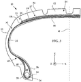
- the tire 10 according to the second embodiment of the figure 3 is not suitable for run flat. Thus, it is devoid of the sidewall inserts 44.
- the tire 10 of the second embodiment comprises hoop reinforcing elements in accordance with the invention.
- the tire 10 of the second embodiment comprises hoop reinforcing elements not in accordance with the invention.
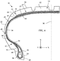
- the tire 10 according to the third embodiment of the figure 4 comprises a sidewall reinforcement 48 preferably comprising a single sidewall reinforcement ply 50.
- the sidewall reinforcement 48 is arranged axially outside the outgoing strand 38 and extends, in each bead 24, axially outside the return strand 40 of the carcass ply 34.
- the sidewall reinforcement 48 may be arranged radially between the outward strand 38 and the return strand 40 of the carcass ply 34.
- the radially inner end 52 of the sidewall reinforcement 48 is radially inside the radially outer end 53 of the return leg 40 of the carcass reinforcement 32.
- the radially outer end 54 of the reinforcement sidewall reinforcement 25 is axially inside the axially outer end 55 of the crown ply radially adjacent to the sidewall reinforcement frame 48, here the radially innermost working ply 18.
- Other configurations of the ends 52 and 54 relative to the ends 53 and 55 are possible and for example described in WO2014040976 .
- the sidewall reinforcement comprises reinforcement elements in accordance with the invention.
- a method for manufacturing a reinforcing element 36 will now be described.
- the method according to the invention can be implemented with ring looms well known to those skilled in the art but also on direct cabling machines.
- a step of obtaining the strand 57 of high modulus textile monofilaments one starts with a yarn of high modulus textile monofilaments and this yarn is twisted in a direction D1 ′ with an initial twist R1 ′. Strand 57 is obtained.
- Each yarn in English “ yarn "), in the initial state, that is to say devoid of twist; in a well-known manner, is formed of a plurality of elementary textile monofilaments, typically several tens to several hundreds, of very fine diameter generally less than 25 ⁇ m. Within each strand '57', 56 ', the elementary textile monofilaments are thus imposed a helical deformation around the axis of the fiber strand.
- D1 'and D2' are identical and here are the Z direction.
- the strands 57, 56 of high and low modulus textile monofilaments are wound around each other in a direction D3 with a twist R3 so that on the one hand, the strand of high modulus textile monofilaments has a residual torsion R1, here substantially non-zero, in a direction D1, and on the other hand, the strand of low-modulus textile monofilaments has a residual torsion R2 in a direction D2.
- the residual twists R1 and R2 are such that R1> R2 in the case where R2 is substantially non-zero and R1 is substantially non-zero in the case where R2 is substantially zero. In this case, in the example of the reinforcing element 36, R1> R2.
- Table 1 compared the characteristics of the reinforcing element 36 according to the invention, of another reinforcing element 37 according to the invention, and other reinforcing elements forming comparative examples.
- PET is marketed by the company Hyosung under the name HSP40 NAA.
- Aramid is marketed by the company Teijin under the name Twaron 1000.
- the breaking forces determined according to the ASTM D 885 / D 885MA standard of January 2010, are measured at 20 ° C on unbleached reinforcing elements (that is to say not glued) which have been subjected to prior conditioning .
- preliminary conditioning is meant the storage of the reinforcing elements (after drying) for at least 24 hours, before measurement, in a standard atmosphere according to the European standard DIN EN 20139 (temperature of 20 ⁇ 2 ° C; humidity of 65 ⁇ 2%).
- the count (or linear density) of the elementary strands or of the reinforcing elements is determined according to standard ASTM D1423.
- the titer is given in tex (weight in grams of 1000 m 3 of product - reminder: 0.111 tex equal to 1 denier).
- Endurance is determined by conducting a flexural endurance test in accordance with ASTM D430-06 (Method A) during which a back and forth movement is made to a semi-finished product comprising several reinforcing elements. embedded in an elastomer matrix in contact with a pulley. At the end of 600,000 cycles, the reinforcing elements are extracted from the elastomer matrix and the breaking force Ft is measured. This breaking force Ft is compared to the breaking force Fr before the bending endurance test. . The decay in% Dt is given by the difference relation (1-Ft / Fr) .100 and the endurance is given by the relation 100.Ft / Fr and is reported in the table.
- NM indicates that the value was not measured.
- the carcass reinforcement 32 of the tire may comprise two carcass plies 34.
Landscapes
- Engineering & Computer Science (AREA)
- Mechanical Engineering (AREA)
- Textile Engineering (AREA)
- Tires In General (AREA)
- Yarns And Mechanical Finishing Of Yarns Or Ropes (AREA)
- Ropes Or Cables (AREA)
- Woven Fabrics (AREA)
Applications Claiming Priority (2)
| Application Number | Priority Date | Filing Date | Title |
|---|---|---|---|
| FR1552699A FR3034435B1 (fr) | 2015-03-31 | 2015-03-31 | Element de renfort hybride a torsions differenciees |
| PCT/EP2016/056702 WO2016156263A1 (fr) | 2015-03-31 | 2016-03-25 | Elément de renfort hybride à torsions différenciées |
Publications (2)
| Publication Number | Publication Date |
|---|---|
| EP3277869A1 EP3277869A1 (fr) | 2018-02-07 |
| EP3277869B1 true EP3277869B1 (fr) | 2021-06-09 |
Family
ID=53496768
Family Applications (1)
| Application Number | Title | Priority Date | Filing Date |
|---|---|---|---|
| EP16714818.8A Active EP3277869B1 (fr) | 2015-03-31 | 2016-03-25 | Élément de renfort hybride à torsions différenciées |
Country Status (6)
| Country | Link |
|---|---|
| US (1) | US10688828B2 (enExample) |
| EP (1) | EP3277869B1 (enExample) |
| JP (1) | JP6806697B2 (enExample) |
| CN (1) | CN107531095B (enExample) |
| FR (1) | FR3034435B1 (enExample) |
| WO (1) | WO2016156263A1 (enExample) |
Families Citing this family (6)
| Publication number | Priority date | Publication date | Assignee | Title |
|---|---|---|---|---|
| IT201600117754A1 (it) * | 2016-11-22 | 2018-05-22 | Pirelli | Pneumatico per motoveicoli |
| CN110325377A (zh) * | 2017-02-22 | 2019-10-11 | 株式会社普利司通 | 充气轮胎 |
| US20210025084A1 (en) * | 2018-03-20 | 2021-01-28 | Compagnie Generale Des Etablissements Michelin | Improved aramid textile cord with an at least triple twist |
| EP3880492B1 (fr) | 2018-11-14 | 2023-02-22 | Compagnie Generale Des Etablissements Michelin | Pneumatique pour véhicule à deux roues comprenant un renfort de frettage hybride |
| CN113661075B (zh) * | 2019-04-17 | 2025-10-03 | 倍耐力轮胎股份公司 | 混合帘线和具有这种帘线的轮胎 |
| DE102021207531A1 (de) | 2021-07-15 | 2023-01-19 | Continental Reifen Deutschland Gmbh | Duplexkord zur Verwendung als Festigkeitsträger in einer Gürtelbandage eines Fahrzeugluftreifens |
Family Cites Families (29)
| Publication number | Priority date | Publication date | Assignee | Title |
|---|---|---|---|---|
| GB1081089A (en) | 1963-11-19 | 1967-08-31 | Dunlop Rubber Co | Improvements in or relating to textile cord material and pneumatic tyres manufacturedtherewith |
| US3603071A (en) * | 1970-04-22 | 1971-09-07 | Goodyear Tire & Rubber | Cords for annular reinforcing tire belts |
| US3977172A (en) | 1975-02-06 | 1976-08-31 | E. I. Du Pont De Nemours And Company | Reinforcement cord |
| US4155394A (en) * | 1977-08-29 | 1979-05-22 | The Goodyear Tire & Rubber Company | Tire cord composite and pneumatic tire |
| US4234030A (en) * | 1978-08-18 | 1980-11-18 | The Goodyear Tire & Rubber Company | Tire carcass structure |
| NL7904496A (nl) | 1979-06-08 | 1980-12-10 | Akzo Nv | Vezel,dradenbundel en koord uit poly-p-fenyleenteref- taalamide. |
| WO1986007393A1 (fr) | 1985-06-12 | 1986-12-18 | Toray Industries, Inc. | Cable pour pneus en alcool polyvinylique |
| FR2589106B1 (fr) | 1985-10-24 | 1988-02-19 | Michelin Rech Tech | Enveloppe de pneumatique dont la carcasse est constituee par une fibre en cellulose regeneree |
| US4877073A (en) * | 1988-02-17 | 1989-10-31 | The Goodyear Tire & Rubber Company | Cables and tires reinforced by said cables |
| US4832101A (en) * | 1988-02-17 | 1989-05-23 | The Goodyear Tire & Rubber Company | Pneumatic tires |
| JP2757940B2 (ja) | 1988-03-28 | 1998-05-25 | 住友ゴム工業株式会社 | 空気入りタイヤ |
| EP0467585B1 (en) | 1990-07-11 | 1995-02-01 | Sumitomo Rubber Industries Limited | Radial tyre for a motorcycle |
| EP0661179B1 (en) * | 1993-12-28 | 1997-05-21 | Sumitomo Rubber Industries Limited | Pneumatic radial tyre |
| FR2737735A1 (fr) | 1995-08-10 | 1997-02-14 | Michelin Rech Tech | Fibres cellulosiques a allongement rupture ameliore |
| US6601378B1 (en) * | 1999-09-08 | 2003-08-05 | Honeywell International Inc. | Hybrid cabled cord and a method to make it |
| WO2002096677A1 (en) | 2001-05-29 | 2002-12-05 | Societe De Technologie Michelin | Runflat tire |
| US6799618B2 (en) * | 2002-12-18 | 2004-10-05 | The Goodyear Tire & Rubber Company | Pneumatic tire having an overlay reinforcement |
| US7484545B2 (en) * | 2005-12-20 | 2009-02-03 | The Goodyear Tire & Rubber Co. | Radial tire for aircraft with specified merged cords |
| DE102008037615A1 (de) * | 2008-12-01 | 2010-06-02 | Continental Reifen Deutschland Gmbh | Hybridkord zur Verwendung als Festigkeitsträger in einer Gürtelbandage eines Fahrzeugluftreifens |
| FR2971266B1 (fr) | 2011-02-03 | 2014-06-27 | Soc Tech Michelin | Materiau textile pourvu d'une colle thermoplastique |
| FR2974583B1 (fr) | 2011-04-28 | 2013-06-14 | Michelin Soc Tech | Cable textile composite aramide-polycetone |
| KR101260390B1 (ko) * | 2011-07-25 | 2013-05-21 | 한국타이어 주식회사 | 아라미드 코드와 나일론 66과의 하이브리드 코드 및 이를 보강 코드로 사용하는 공기입 타이어 |
| FR2995251B1 (fr) | 2012-09-11 | 2014-08-29 | Michelin & Cie | Pneumatique comportant une armature de flanc supplementaire. |
| FR2996807B1 (fr) | 2012-10-12 | 2015-01-02 | Michelin & Cie | Pneumatique adapte pour un roulage a plat comprenant nappe de carcasse hybride. |
| FR3005438B1 (fr) | 2013-05-13 | 2015-04-24 | Michelin & Cie | Pneumatique adapte pour un roulage a plat comprenant une nappe de carcasse en polyester |
| FR3029541B1 (fr) | 2014-12-09 | 2017-07-28 | Michelin & Cie | Cable textile aramide a au moins triple torsion |
| FR3029539B1 (fr) | 2014-12-09 | 2017-05-19 | Michelin & Cie | Cable textile a au moins triple torsion |
| FR3029542B1 (fr) | 2014-12-09 | 2017-07-28 | Michelin & Cie | Cable textile haut module a au moins triple torsion |
| KR101602605B1 (ko) * | 2015-06-29 | 2016-03-21 | 코오롱인더스트리 주식회사 | 하이브리드 타이어 코드 및 그 제조방법 |
-
2015
- 2015-03-31 FR FR1552699A patent/FR3034435B1/fr not_active Expired - Fee Related
-
2016
- 2016-03-25 JP JP2017550487A patent/JP6806697B2/ja active Active
- 2016-03-25 CN CN201680020491.3A patent/CN107531095B/zh active Active
- 2016-03-25 US US15/554,583 patent/US10688828B2/en active Active
- 2016-03-25 WO PCT/EP2016/056702 patent/WO2016156263A1/fr not_active Ceased
- 2016-03-25 EP EP16714818.8A patent/EP3277869B1/fr active Active
Also Published As
| Publication number | Publication date |
|---|---|
| EP3277869A1 (fr) | 2018-02-07 |
| FR3034435A1 (fr) | 2016-10-07 |
| WO2016156263A1 (fr) | 2016-10-06 |
| FR3034435B1 (fr) | 2018-03-02 |
| JP2018513925A (ja) | 2018-05-31 |
| CN107531095A (zh) | 2018-01-02 |
| JP6806697B2 (ja) | 2021-01-06 |
| US20180099529A1 (en) | 2018-04-12 |
| US10688828B2 (en) | 2020-06-23 |
| CN107531095B (zh) | 2020-01-17 |
Similar Documents
| Publication | Publication Date | Title |
|---|---|---|
| EP2906434B1 (fr) | Pneumatique adapté pour un roulage à plat comprenant nappe de carcasse hybride | |
| EP3277869B1 (fr) | Élément de renfort hybride à torsions différenciées | |
| EP2702194B1 (fr) | Cable textile composite aramide-polycetone | |
| EP2416955B1 (fr) | Bandage pneumatique dont la ceinture est renforcee par un film de polymere thermoplastique | |
| EP3515727B1 (fr) | Composite d'élastomère et pneumatique comprenant ce composite | |
| EP2996887B1 (fr) | Composition de caoutchouc à haute processabilité pour pneumatique adapté pour un roulage à plat | |
| WO2018051032A1 (fr) | Élément de renfort, composite d'élastomère et pneumatique comprenant cet élément de renfort | |
| EP3768526B1 (fr) | Pneumatique comprenant une unique nappe de carcasse avec une profondeur de déformation dans le flanc améliorée après rodage | |
| EP3448695B1 (fr) | Pneu avion ayant une armature de carcasse à endurance améliorée | |
| FR3029539A1 (fr) | Cable textile a au moins triple torsion | |
| EP3768882A1 (fr) | Câblé textile aramide perfectionne à au moins triple torsion | |
| WO2016124418A1 (fr) | Pneu radial ayant une structure de ceinture améliorée | |
| EP3727888B1 (fr) | Pneumatique comprenant des éléments de renfort sous forme de bandelettes stratifiées | |
| EP3853045B1 (fr) | Pneumatique comportant une armature de carcasse formee d'une unique couche d'elements de renforcement textiles | |
| EP4100264B1 (fr) | Pneumatique pour véhicule agricole comprenant un élément de renfort de carcasse hybride | |
| EP3880492B1 (fr) | Pneumatique pour véhicule à deux roues comprenant un renfort de frettage hybride | |
| FR3137868A1 (fr) | Tissu pour pneumatique comprenant des éléments de renfort comprenant un assemblage constitué de deux brins multifilamentaires de polyamide 5,6 | |
| WO2008128917A1 (fr) | Pneumatique pour vehicule comportant des renforts dans les flancs |
Legal Events
| Date | Code | Title | Description |
|---|---|---|---|
| STAA | Information on the status of an ep patent application or granted ep patent |
Free format text: STATUS: THE INTERNATIONAL PUBLICATION HAS BEEN MADE |
|
| PUAI | Public reference made under article 153(3) epc to a published international application that has entered the european phase |
Free format text: ORIGINAL CODE: 0009012 |
|
| STAA | Information on the status of an ep patent application or granted ep patent |
Free format text: STATUS: REQUEST FOR EXAMINATION WAS MADE |
|
| 17P | Request for examination filed |
Effective date: 20171102 |
|
| AK | Designated contracting states |
Kind code of ref document: A1 Designated state(s): AL AT BE BG CH CY CZ DE DK EE ES FI FR GB GR HR HU IE IS IT LI LT LU LV MC MK MT NL NO PL PT RO RS SE SI SK SM TR |
|
| AX | Request for extension of the european patent |
Extension state: BA ME |
|
| DAV | Request for validation of the european patent (deleted) | ||
| DAX | Request for extension of the european patent (deleted) | ||
| RAP1 | Party data changed (applicant data changed or rights of an application transferred) |
Owner name: COMPAGNIE GENERALE DES ETABLISSEMENTS MICHELIN |
|
| GRAP | Despatch of communication of intention to grant a patent |
Free format text: ORIGINAL CODE: EPIDOSNIGR1 |
|
| STAA | Information on the status of an ep patent application or granted ep patent |
Free format text: STATUS: GRANT OF PATENT IS INTENDED |
|
| INTG | Intention to grant announced |
Effective date: 20210222 |
|
| GRAS | Grant fee paid |
Free format text: ORIGINAL CODE: EPIDOSNIGR3 |
|
| GRAA | (expected) grant |
Free format text: ORIGINAL CODE: 0009210 |
|
| STAA | Information on the status of an ep patent application or granted ep patent |
Free format text: STATUS: THE PATENT HAS BEEN GRANTED |
|
| AK | Designated contracting states |
Kind code of ref document: B1 Designated state(s): AL AT BE BG CH CY CZ DE DK EE ES FI FR GB GR HR HU IE IS IT LI LT LU LV MC MK MT NL NO PL PT RO RS SE SI SK SM TR |
|
| REG | Reference to a national code |
Ref country code: GB Ref legal event code: FG4D Free format text: NOT ENGLISH |
|
| REG | Reference to a national code |
Ref country code: CH Ref legal event code: EP Ref country code: AT Ref legal event code: REF Ref document number: 1400576 Country of ref document: AT Kind code of ref document: T Effective date: 20210615 |
|
| REG | Reference to a national code |
Ref country code: DE Ref legal event code: R096 Ref document number: 602016059090 Country of ref document: DE |
|
| REG | Reference to a national code |
Ref country code: IE Ref legal event code: FG4D Free format text: LANGUAGE OF EP DOCUMENT: FRENCH |
|
| REG | Reference to a national code |
Ref country code: LT Ref legal event code: MG9D |
|
| PG25 | Lapsed in a contracting state [announced via postgrant information from national office to epo] |
Ref country code: HR Free format text: LAPSE BECAUSE OF FAILURE TO SUBMIT A TRANSLATION OF THE DESCRIPTION OR TO PAY THE FEE WITHIN THE PRESCRIBED TIME-LIMIT Effective date: 20210609 Ref country code: BG Free format text: LAPSE BECAUSE OF FAILURE TO SUBMIT A TRANSLATION OF THE DESCRIPTION OR TO PAY THE FEE WITHIN THE PRESCRIBED TIME-LIMIT Effective date: 20210909 Ref country code: FI Free format text: LAPSE BECAUSE OF FAILURE TO SUBMIT A TRANSLATION OF THE DESCRIPTION OR TO PAY THE FEE WITHIN THE PRESCRIBED TIME-LIMIT Effective date: 20210609 Ref country code: LT Free format text: LAPSE BECAUSE OF FAILURE TO SUBMIT A TRANSLATION OF THE DESCRIPTION OR TO PAY THE FEE WITHIN THE PRESCRIBED TIME-LIMIT Effective date: 20210609 |
|
| REG | Reference to a national code |
Ref country code: AT Ref legal event code: MK05 Ref document number: 1400576 Country of ref document: AT Kind code of ref document: T Effective date: 20210609 |
|
| REG | Reference to a national code |
Ref country code: NL Ref legal event code: MP Effective date: 20210609 |
|
| PG25 | Lapsed in a contracting state [announced via postgrant information from national office to epo] |
Ref country code: SE Free format text: LAPSE BECAUSE OF FAILURE TO SUBMIT A TRANSLATION OF THE DESCRIPTION OR TO PAY THE FEE WITHIN THE PRESCRIBED TIME-LIMIT Effective date: 20210609 Ref country code: RS Free format text: LAPSE BECAUSE OF FAILURE TO SUBMIT A TRANSLATION OF THE DESCRIPTION OR TO PAY THE FEE WITHIN THE PRESCRIBED TIME-LIMIT Effective date: 20210609 Ref country code: NO Free format text: LAPSE BECAUSE OF FAILURE TO SUBMIT A TRANSLATION OF THE DESCRIPTION OR TO PAY THE FEE WITHIN THE PRESCRIBED TIME-LIMIT Effective date: 20210909 Ref country code: LV Free format text: LAPSE BECAUSE OF FAILURE TO SUBMIT A TRANSLATION OF THE DESCRIPTION OR TO PAY THE FEE WITHIN THE PRESCRIBED TIME-LIMIT Effective date: 20210609 Ref country code: GR Free format text: LAPSE BECAUSE OF FAILURE TO SUBMIT A TRANSLATION OF THE DESCRIPTION OR TO PAY THE FEE WITHIN THE PRESCRIBED TIME-LIMIT Effective date: 20210910 |
|
| PG25 | Lapsed in a contracting state [announced via postgrant information from national office to epo] |
Ref country code: AT Free format text: LAPSE BECAUSE OF FAILURE TO SUBMIT A TRANSLATION OF THE DESCRIPTION OR TO PAY THE FEE WITHIN THE PRESCRIBED TIME-LIMIT Effective date: 20210609 Ref country code: PT Free format text: LAPSE BECAUSE OF FAILURE TO SUBMIT A TRANSLATION OF THE DESCRIPTION OR TO PAY THE FEE WITHIN THE PRESCRIBED TIME-LIMIT Effective date: 20211011 Ref country code: NL Free format text: LAPSE BECAUSE OF FAILURE TO SUBMIT A TRANSLATION OF THE DESCRIPTION OR TO PAY THE FEE WITHIN THE PRESCRIBED TIME-LIMIT Effective date: 20210609 Ref country code: RO Free format text: LAPSE BECAUSE OF FAILURE TO SUBMIT A TRANSLATION OF THE DESCRIPTION OR TO PAY THE FEE WITHIN THE PRESCRIBED TIME-LIMIT Effective date: 20210609 Ref country code: ES Free format text: LAPSE BECAUSE OF FAILURE TO SUBMIT A TRANSLATION OF THE DESCRIPTION OR TO PAY THE FEE WITHIN THE PRESCRIBED TIME-LIMIT Effective date: 20210609 Ref country code: SK Free format text: LAPSE BECAUSE OF FAILURE TO SUBMIT A TRANSLATION OF THE DESCRIPTION OR TO PAY THE FEE WITHIN THE PRESCRIBED TIME-LIMIT Effective date: 20210609 Ref country code: SM Free format text: LAPSE BECAUSE OF FAILURE TO SUBMIT A TRANSLATION OF THE DESCRIPTION OR TO PAY THE FEE WITHIN THE PRESCRIBED TIME-LIMIT Effective date: 20210609 Ref country code: CZ Free format text: LAPSE BECAUSE OF FAILURE TO SUBMIT A TRANSLATION OF THE DESCRIPTION OR TO PAY THE FEE WITHIN THE PRESCRIBED TIME-LIMIT Effective date: 20210609 Ref country code: EE Free format text: LAPSE BECAUSE OF FAILURE TO SUBMIT A TRANSLATION OF THE DESCRIPTION OR TO PAY THE FEE WITHIN THE PRESCRIBED TIME-LIMIT Effective date: 20210609 |
|
| PG25 | Lapsed in a contracting state [announced via postgrant information from national office to epo] |
Ref country code: PL Free format text: LAPSE BECAUSE OF FAILURE TO SUBMIT A TRANSLATION OF THE DESCRIPTION OR TO PAY THE FEE WITHIN THE PRESCRIBED TIME-LIMIT Effective date: 20210609 |
|
| REG | Reference to a national code |
Ref country code: DE Ref legal event code: R097 Ref document number: 602016059090 Country of ref document: DE |
|
| PLBE | No opposition filed within time limit |
Free format text: ORIGINAL CODE: 0009261 |
|
| STAA | Information on the status of an ep patent application or granted ep patent |
Free format text: STATUS: NO OPPOSITION FILED WITHIN TIME LIMIT |
|
| PG25 | Lapsed in a contracting state [announced via postgrant information from national office to epo] |
Ref country code: DK Free format text: LAPSE BECAUSE OF FAILURE TO SUBMIT A TRANSLATION OF THE DESCRIPTION OR TO PAY THE FEE WITHIN THE PRESCRIBED TIME-LIMIT Effective date: 20210609 |
|
| 26N | No opposition filed |
Effective date: 20220310 |
|
| PG25 | Lapsed in a contracting state [announced via postgrant information from national office to epo] |
Ref country code: AL Free format text: LAPSE BECAUSE OF FAILURE TO SUBMIT A TRANSLATION OF THE DESCRIPTION OR TO PAY THE FEE WITHIN THE PRESCRIBED TIME-LIMIT Effective date: 20210609 |
|
| PG25 | Lapsed in a contracting state [announced via postgrant information from national office to epo] |
Ref country code: IT Free format text: LAPSE BECAUSE OF FAILURE TO SUBMIT A TRANSLATION OF THE DESCRIPTION OR TO PAY THE FEE WITHIN THE PRESCRIBED TIME-LIMIT Effective date: 20210609 |
|
| PG25 | Lapsed in a contracting state [announced via postgrant information from national office to epo] |
Ref country code: MC Free format text: LAPSE BECAUSE OF FAILURE TO SUBMIT A TRANSLATION OF THE DESCRIPTION OR TO PAY THE FEE WITHIN THE PRESCRIBED TIME-LIMIT Effective date: 20210609 |
|
| REG | Reference to a national code |
Ref country code: CH Ref legal event code: PL |
|
| GBPC | Gb: european patent ceased through non-payment of renewal fee |
Effective date: 20220325 |
|
| REG | Reference to a national code |
Ref country code: BE Ref legal event code: MM Effective date: 20220331 |
|
| PG25 | Lapsed in a contracting state [announced via postgrant information from national office to epo] |
Ref country code: LU Free format text: LAPSE BECAUSE OF NON-PAYMENT OF DUE FEES Effective date: 20220325 Ref country code: LI Free format text: LAPSE BECAUSE OF NON-PAYMENT OF DUE FEES Effective date: 20220331 Ref country code: IE Free format text: LAPSE BECAUSE OF NON-PAYMENT OF DUE FEES Effective date: 20220325 Ref country code: GB Free format text: LAPSE BECAUSE OF NON-PAYMENT OF DUE FEES Effective date: 20220325 Ref country code: CH Free format text: LAPSE BECAUSE OF NON-PAYMENT OF DUE FEES Effective date: 20220331 |
|
| PG25 | Lapsed in a contracting state [announced via postgrant information from national office to epo] |
Ref country code: BE Free format text: LAPSE BECAUSE OF NON-PAYMENT OF DUE FEES Effective date: 20220331 |
|
| PG25 | Lapsed in a contracting state [announced via postgrant information from national office to epo] |
Ref country code: HU Free format text: LAPSE BECAUSE OF FAILURE TO SUBMIT A TRANSLATION OF THE DESCRIPTION OR TO PAY THE FEE WITHIN THE PRESCRIBED TIME-LIMIT; INVALID AB INITIO Effective date: 20160325 |
|
| PG25 | Lapsed in a contracting state [announced via postgrant information from national office to epo] |
Ref country code: MK Free format text: LAPSE BECAUSE OF FAILURE TO SUBMIT A TRANSLATION OF THE DESCRIPTION OR TO PAY THE FEE WITHIN THE PRESCRIBED TIME-LIMIT Effective date: 20210609 Ref country code: CY Free format text: LAPSE BECAUSE OF FAILURE TO SUBMIT A TRANSLATION OF THE DESCRIPTION OR TO PAY THE FEE WITHIN THE PRESCRIBED TIME-LIMIT Effective date: 20210609 |
|
| PG25 | Lapsed in a contracting state [announced via postgrant information from national office to epo] |
Ref country code: MT Free format text: LAPSE BECAUSE OF FAILURE TO SUBMIT A TRANSLATION OF THE DESCRIPTION OR TO PAY THE FEE WITHIN THE PRESCRIBED TIME-LIMIT Effective date: 20210609 |
|
| PGFP | Annual fee paid to national office [announced via postgrant information from national office to epo] |
Ref country code: DE Payment date: 20250319 Year of fee payment: 10 |
|
| PGFP | Annual fee paid to national office [announced via postgrant information from national office to epo] |
Ref country code: FR Payment date: 20250325 Year of fee payment: 10 |