EP3276801A1 - Method of manufacturing a rotor assembly, in particular for an electric motor of the ipm-pmasr type - Google Patents
Method of manufacturing a rotor assembly, in particular for an electric motor of the ipm-pmasr type Download PDFInfo
- Publication number
- EP3276801A1 EP3276801A1 EP17182913.8A EP17182913A EP3276801A1 EP 3276801 A1 EP3276801 A1 EP 3276801A1 EP 17182913 A EP17182913 A EP 17182913A EP 3276801 A1 EP3276801 A1 EP 3276801A1
- Authority
- EP
- European Patent Office
- Prior art keywords
- lamination
- lamination stack
- cavities
- rotor assembly
- polymer
- Prior art date
- Legal status (The legal status is an assumption and is not a legal conclusion. Google has not performed a legal analysis and makes no representation as to the accuracy of the status listed.)
- Withdrawn
Links
Images


Classifications
-
- H—ELECTRICITY
- H02—GENERATION; CONVERSION OR DISTRIBUTION OF ELECTRIC POWER
- H02K—DYNAMO-ELECTRIC MACHINES
- H02K15/00—Methods or apparatus specially adapted for manufacturing, assembling, maintaining or repairing of dynamo-electric machines
- H02K15/02—Methods or apparatus specially adapted for manufacturing, assembling, maintaining or repairing of dynamo-electric machines of stator or rotor bodies
- H02K15/03—Methods or apparatus specially adapted for manufacturing, assembling, maintaining or repairing of dynamo-electric machines of stator or rotor bodies having permanent magnets
-
- H—ELECTRICITY
- H02—GENERATION; CONVERSION OR DISTRIBUTION OF ELECTRIC POWER
- H02K—DYNAMO-ELECTRIC MACHINES
- H02K1/00—Details of the magnetic circuit
- H02K1/06—Details of the magnetic circuit characterised by the shape, form or construction
- H02K1/22—Rotating parts of the magnetic circuit
- H02K1/27—Rotor cores with permanent magnets
- H02K1/2706—Inner rotors
- H02K1/272—Inner rotors the magnetisation axis of the magnets being perpendicular to the rotor axis
- H02K1/274—Inner rotors the magnetisation axis of the magnets being perpendicular to the rotor axis the rotor consisting of two or more circumferentially positioned magnets
- H02K1/2753—Inner rotors the magnetisation axis of the magnets being perpendicular to the rotor axis the rotor consisting of two or more circumferentially positioned magnets the rotor consisting of magnets or groups of magnets arranged with alternating polarity
- H02K1/276—Magnets embedded in the magnetic core, e.g. interior permanent magnets [IPM]
- H02K1/2766—Magnets embedded in the magnetic core, e.g. interior permanent magnets [IPM] having a flux concentration effect
-
- H—ELECTRICITY
- H02—GENERATION; CONVERSION OR DISTRIBUTION OF ELECTRIC POWER
- H02K—DYNAMO-ELECTRIC MACHINES
- H02K2201/00—Specific aspects not provided for in the other groups of this subclass relating to the magnetic circuits
- H02K2201/06—Magnetic cores, or permanent magnets characterised by their skew
-
- H—ELECTRICITY
- H02—GENERATION; CONVERSION OR DISTRIBUTION OF ELECTRIC POWER
- H02K—DYNAMO-ELECTRIC MACHINES
- H02K7/00—Arrangements for handling mechanical energy structurally associated with dynamo-electric machines, e.g. structural association with mechanical driving motors or auxiliary dynamo-electric machines
- H02K7/04—Balancing means
Definitions
- the present invention in its most general aspect, refers to a method for manufacturing a rotor assembly and a respective electric motor.
- the electric motor is of the IPM-PMASR type (Interior Permanent Magnet - Permanent Magnet Assisted Synchronous Reluctance motor).
- the rotor assembly and the motor manufactured according to the present invention are employed in the electric drive of the main drum of a washing machine.
- said rotor assembly and motor can be employed in a wide range of industrial applications, and are particularly suited for controlled drives with a high power density, for instance electric vehicles' drives.
- Permanent-magnet assisted synchronous reluctance motor have been developed in the last decades and they represent a viable alternative to induction or permanent magnet synchronous motors for controlled drive applications.
- a typical motor layout disclosed in US Patent N. 5,818,140 , has the rotor assembled out of axially stacked laminations.
- the rotor is subdivided in an even number of angular sectors, each sector having a same layout of cavities.
- the cavities are roughly arc-shaped, with their convex side pointing toward the centre of the rotor.
- Permanent-magnets are inserted in at least some of said cavities, so that adjacent sectors have magnets with opposite polarities.
- a rotor having the above-mentioned layout can be reliably manufactured in a cost-effective way.
- the single laminations are punched in order to open slots and then stacked on a press, so that the superposed slots define the axial cavities.
- the permanent magnets are eventually inserted into the cavities.
- a first drawback derives from the comparatively high cogging torque of the resulting electric motor, which causes unwanted noise and vibration particularly at slower rotational speeds.
- Another drawback relates to the balancing of the rotor assembly.
- a balancing step is typically carried out by removing material from the laminations at both ends of the rotor stack.
- such an operation would result in an unacceptable structural weakening of the whole rotor, and therefore has to be avoided.
- the technical problem at the basis of the present invention is therefore that of overcoming the above-mentioned drawbacks of the method of manufacturing a permanent-magnet assisted synchronous reluctance motor according to the prior art.
- the inner slots are substantially arc-shaped, their convex side pointing toward the center of their lamination, said inner slots being configured in an even number of groups, each group being confined in a different circular sector of the lamination.
- the permanent magnets defined in the cavities made up by the inner slots of adjacent groups are preferably magnetized with opposite polarities.
- the skewed design of the rotor assembly obtained by subsequent rotations of the single laminations is meant to reduce the cogging torque and the related drawbacks, such as excessive noise and vibrations.
- the relative angle of rotation between two subsequent laminations in the stack is accurately chosen in order to ensure smooth operation of the resulting electric motor and to minimize the cogging torque.
- the relative angle can be comprised between 10°/N and 20°/N, being preferably equal to 15°/N.
- the manufacturing method may further comprise a step of applying at least a balancing plate over one or both ends of the lamination stack.
- the balancing can be advantageously performed without removing material from the lamination, and thus without unduly weakening the rotor structure.
- the balancing plate can be advantageously made in aluminum or aluminum alloy.
- the polymer-bonded magnetic compound may further define at least one anchoring feature protruding in the axial direction with respect to the lamination stack, said balancing plate being attached to said anchoring feature.
- two anchoring features are provided, at both ends of the lamination stack.
- said anchoring feature is in the form of an anchoring rim, which is housed in a corresponding groove of the balancing plate.
- said balancing plate is attached to said anchoring feature by means of a glue, for instance an epoxy resin heat resistant at a temperature of at least 130°C.
- a glue for instance an epoxy resin heat resistant at a temperature of at least 130°C.
- the method of manufacturing may then comprise a step of balancing the rotor assembly by removing material from the balancing plate, preferably by blind drilling of the plate surface.
- the method of manufacturing may further comprise a step of magnetizing the polymer-bonded magnetic compound, so that the inner permanent magnets are magnetized with different polarities.
- said step of magnetizing the polymer-bonded magnetic compound is preferably performed during injection molding, by suitably applying magnetic fields within a mold housing the lamination stack.
- the method may advantageously comprise a step of press fitting an axle in a central hole of the lamination stack, preferably performed before the step of injection molding.
- the injection-molding step may be performed by inserting the lamination stack in a housing within a mold, the polymer-bonded magnetic compound being injected laterally into a feeder of the mold placed over the housing.
- the rotor assembly manufactured according to the present invention is generally designated with reference number 1, while the whole permanent-magnet-assisted synchronous motor comprising said rotor assembly is referenced with 10.
- the motor is meant to drive the drum of a washing machine.
- the rotor assembly 1 is made up of a lamination stack 20, composed of a plurality of laminations 2 made of electrical steel.
- each lamination 2 has a circular shape, and is divided in an even number of circular sectors, four in the preferred embodiment depicted herewith.
- Each circular sector features a plurality of roughly arc-shaped slots 3, the convex side of which points toward the centre of the lamination. In the preferred embodiment depicted herewith, each circular sector has three slots 3.
- the slots 3 are divided by a radial reinforcing bridge 31, which cuts the circular sector and the slots 3 in two symmetrical halves.
- the stacked laminations 2 are slightly rotated, by a predefined angle ⁇ /N (N being the total number of the laminations 2), one with respect to the following, so that the slots 3 define axially skewed cavities 30 of the lamination stack 20.
- top and bottom laminations 2 of the lamination stack are depicted, respectively in solid and dashed line.
- the total angle ⁇ between the top and bottom laminations 2 is preferably equal to 15°.
- the cavities 30 are filled by a polymer bonded magnetic compound which is magnetized in order to define permanent magnets 4.
- the permanent magnets 4 pertaining to a single circular sector have the same polarity. Adjacent sectors feature permanent magnets 4 with opposite polarity.
- the lamination stack 20 is further equipped with a pair of anchoring rims 5, respectively projecting from the first and last lamination 2 of the lamination pack 20.
- the anchoring rims 5 are made of the same polymer bonded material that fills the cavities 30, and covers an annular region close to the periphery of the lamination stack 20.
- balancing plates 6 are mirror-shaped, thin cylindrical disks made of aluminum, topping the lamination stack 20 at both ends, providing excess material that can be removed for balancing purpose.
- Each balancing plate 6 has a main circumferential groove 60 on the lamination side, which mates and houses the respective anchoring rim 5 on the lamination stack.
- a thinner secondary groove 61 is also provided on the same plate side, on an inner position with respect to the main groove 60.
- a wider circumferential groove 62 is obtained.
- the lamination stack 20 as well as the balancing plates 6 are traversed by a shaft 7, supported by bearings 70, and which is equipped at one of its ends with a pulley 71 meant to drive a washing machine drum through a belt (not shown).
- stator assembly 1 is part of permanent-magnet-assisted synchronous motor 10 further comprising a stator assembly 11, made of a stator lamination stack 12 with open slots traversed by windings 13, preferably aluminum windings.
- the stator assembly 11 is shaped according to the relevant art of permanent-magnet-assisted synchronous motors, see for instance US 5,818,140 .
- the stator assembly 11 is held between a front support 14 and a back support 15, both made of plastic material.
- Each support 14, 15 has four brackets departing from a common hub and defining a cup-shaped cage; the outer end of the brackets being connected by an outer rim.
- the cup-shaped brackets-and-rim structures are respectively fitted at the front and back ends of the stator assembly 11.
- the brackets of the front and back supports 14, 15 are connected together by means of threaded connectors.
- the hubs of the front and back supports 14, 15 house the bearings 70 supporting the rotor assembly 1, which is then held in position surrounded by the stator assembly 11.
- a method of manufacturing the previously described rotor assembly 1 comprises the following steps.
- the laminations 2 are punched out of a sheet of electrical steel.
- the same punch and die, defining the lamination slots 3, can be employed for all laminations 2.
- each lamination 2 is slightly rotated with respect to the previous one, so that the resulting lamination stack 20 has skewed cavities 30 defined by the successive slots 3.
- the shaft 7 is press fitted in a central cylindrical hole of the lamination stack 20, possibly right after the step of stacking the laminations 2.
- the insertion of the shaft 7 solidly binds the laminations 2 together.
- the mold 100 comprises a housing or seat 120 for the stack-and-shaft assembly, which is placed with the shaft 7 in a vertical position.
- the mold 100 comprises an upper fixed portion 110 and a lower movable portion 130.
- the fixed portion 110 is made of a plurality of stacked metal plates; between the top and the second from the top plates, in the area of A, a feeder (not shown) is provided that is connected with sprues to the housing 120.
- magnetizing means 140 are provided for defining a strong magnetic field in order to permanently magnetize the polymer bonded magnetic compound within the cavities 30.
- an injection molding step is performed.
- the polymer bonded magnetic compound is injected and overmolded on the lamination stack 20.
- the molding compound completely or partially fills the cavities 30, and overflows above and below the lamination stack 20 to define the anchoring rims 5.
- the molding compound is injected through horizontal ducts into the feeder.
- a vertical injection can be also envisaged, but the feeding nozzle has to be adequately heated in order to maintain a high flowability of the compound.
- the molding compound preferably comprises ferrite bound by a thermosetting polymer. or as an alternative rare earth elements bound by a thermosetting polymer.
- the thermosetting polymer may be an epoxy resin.
- the magnetizing means 140 are activated so as to permanently magnetize the molding compound trapped within the cavities 30.
- the overmolded lamination stack 20 is extracted from the mold 100 and the balancing plates 6 are glued to the anchoring rims 5, preferably by means of an epoxy resin, heat resistant at a temperature of at least 130°C.
- the pulley 71 is then fitted at the end of the shaft 7.
- the resulting rotor assembly 1 is balanced by blind drilling the end surface of the balancing plates 6.
- the rotor assembly 1 and the stator assembly 11 are assembled together.
- the shaft 7 is mounted on bearings 70, which are housed in the respective hubs of the front and back supports 14, 15.
- the supports 14, 15 are further placed over the opposite ends of the stator assembly 11.
Abstract
Method of manufacturing a rotor assembly for a permanent-magnet-assisted synchronous motor, comprising the following steps:
- cutting a plurality of laminations (2) of equal shape, each lamination being substantially circular and having a plurality of inner slots (3);
- stacking said laminations (2) together so as to form a lamination stack (20), each lamination (2) being rotated of a predetermined angle with respect to the underlying one so that the slots (3) define continuous, axially skewed cavities (30) within the lamination stack (20);
- injecting, through injection-molding, a polymer-bonded magnetic compound within said cavities (30) in order to define inner permanent magnets (4) of the rotor assembly (1) filling said cavities (30).
Description
- The present invention, in its most general aspect, refers to a method for manufacturing a rotor assembly and a respective electric motor.
- In particular, the electric motor is of the IPM-PMASR type (Interior Permanent Magnet - Permanent Magnet Assisted Synchronous Reluctance motor).
- In a preferred example, the rotor assembly and the motor manufactured according to the present invention are employed in the electric drive of the main drum of a washing machine.
- However, said rotor assembly and motor can be employed in a wide range of industrial applications, and are particularly suited for controlled drives with a high power density, for instance electric vehicles' drives.
- Permanent-magnet assisted synchronous reluctance motor have been developed in the last decades and they represent a viable alternative to induction or permanent magnet synchronous motors for controlled drive applications.
- A typical motor layout, disclosed in
US Patent N. 5,818,140 , has the rotor assembled out of axially stacked laminations. The rotor is subdivided in an even number of angular sectors, each sector having a same layout of cavities. The cavities are roughly arc-shaped, with their convex side pointing toward the centre of the rotor. Permanent-magnets are inserted in at least some of said cavities, so that adjacent sectors have magnets with opposite polarities. - A rotor having the above-mentioned layout can be reliably manufactured in a cost-effective way. The single laminations are punched in order to open slots and then stacked on a press, so that the superposed slots define the axial cavities. The permanent magnets are eventually inserted into the cavities.
- Nonetheless, the above-mentioned process and the resulting products still present some drawbacks.
- A first drawback derives from the comparatively high cogging torque of the resulting electric motor, which causes unwanted noise and vibration particularly at slower rotational speeds.
- Other drawbacks derive from the housing of permanent magnets within the cavities. In first instance, the introduction of the permanent magnets results in a time-consuming operation impacting on the manufacturing costs of the electric motor. In second instance, the insertion of the magnet is a strong design constraint and usually involves a sub-optimal layout for the magnetic circuit of the rotor.
- Another drawback relates to the balancing of the rotor assembly. In asynchronous as well as universal motors, a balancing step is typically carried out by removing material from the laminations at both ends of the rotor stack. However, with the previously-described rotor layout, such an operation would result in an unacceptable structural weakening of the whole rotor, and therefore has to be avoided.
- The technical problem at the basis of the present invention is therefore that of overcoming the above-mentioned drawbacks of the method of manufacturing a permanent-magnet assisted synchronous reluctance motor according to the prior art.
- The above-mentioned technical problem is solved by a method of manufacturing a rotor assembly for a permanent-magnet assisted synchronous motor, comprising the following steps:
- cutting a plurality of laminations of equal shape, each lamination being substantially circular and having a plurality of inner slots;
- stacking said laminations together so as to form a lamination stack, each lamination being rotated of a predetermined angle with respect to the underlying one so that the slots define continuous, axially skewed cavities within the lamination stack;
- injecting, through injection-molding, a polymer-bonded magnetic compound within said cavities in order to define inner permanent magnets of the rotor assembly filling said cavities.
- In a preferred way, and according to a typical configuration of the permanent-magnet assisted synchronous motor, the inner slots are substantially arc-shaped, their convex side pointing toward the center of their lamination, said inner slots being configured in an even number of groups, each group being confined in a different circular sector of the lamination.
- The permanent magnets defined in the cavities made up by the inner slots of adjacent groups are preferably magnetized with opposite polarities.
- The skewed design of the rotor assembly obtained by subsequent rotations of the single laminations is meant to reduce the cogging torque and the related drawbacks, such as excessive noise and vibrations.
- The use of a polymer-bonded magnetic compound filling the skewed cavities makes it easy to manufacture the rotor assembly where the non-straight shape of the cavities would have rendered difficult, if not impossible, the positioning of traditional permanent magnets.
- The relative angle of rotation between two subsequent laminations in the stack is accurately chosen in order to ensure smooth operation of the resulting electric motor and to minimize the cogging torque. By way of example, being N the number of laminations in the stack, the relative angle can be comprised between 10°/N and 20°/N, being preferably equal to 15°/N.
- The manufacturing method may further comprise a step of applying at least a balancing plate over one or both ends of the lamination stack.
- By adding a balancing plate to the lamination stack, the balancing can be advantageously performed without removing material from the lamination, and thus without unduly weakening the rotor structure.
- The balancing plate can be advantageously made in aluminum or aluminum alloy.
- During the injection step, the polymer-bonded magnetic compound may further define at least one anchoring feature protruding in the axial direction with respect to the lamination stack, said balancing plate being attached to said anchoring feature.
- Preferably, two anchoring features are provided, at both ends of the lamination stack.
- Preferably, said anchoring feature is in the form of an anchoring rim, which is housed in a corresponding groove of the balancing plate.
- Preferably, said balancing plate is attached to said anchoring feature by means of a glue, for instance an epoxy resin heat resistant at a temperature of at least 130°C.
- The method of manufacturing may then comprise a step of balancing the rotor assembly by removing material from the balancing plate, preferably by blind drilling of the plate surface.
- The method of manufacturing may further comprise a step of magnetizing the polymer-bonded magnetic compound, so that the inner permanent magnets are magnetized with different polarities.
- In particular, said step of magnetizing the polymer-bonded magnetic compound is preferably performed during injection molding, by suitably applying magnetic fields within a mold housing the lamination stack.
- The method may advantageously comprise a step of press fitting an axle in a central hole of the lamination stack, preferably performed before the step of injection molding.
- The injection-molding step may be performed by inserting the lamination stack in a housing within a mold, the polymer-bonded magnetic compound being injected laterally into a feeder of the mold placed over the housing.
- The above-mentioned technical problem is equally solved by a method of manufacturing a permanent-magnet assisted synchronous motor, comprising the one or more of the above-mentioned steps of manufacturing a rotor assembly.
- Further characteristics and advantages of the invention will become clear from the following description of a specific embodiment given by way of non-limiting example, with reference to the enclosed drawings.
-
-
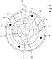
Figure 1 shows a top view of a lamination stack obtained by the manufacturing method according to the invention; -
Figure 2 shows a cross-sectional side view of the lamination stack ofFigure 1 ; -
Figure 3 shows a side view of a rotor assembly obtained by the manufacturing method according to the invention; -
Figure 3A shows an enlarged detail A of the rotor assembly inFigure 3 ; -
Figure 4 shows a top view of a balancing plate assembled in the manufacturing method according to the invention; -
Figure 5 shows a cross-sectional side view of the balancing plate ofFigure 4 ; -
Figure 6 shows a cross-sectional side view of a permanent-magnet-assisted synchronous motor obtained by the manufacturing method according to the invention; -
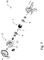
Figure 7 shows a perspective exploded view of the permanent-magnet-assisted synchronous motor ofFigure 6 ; -
Figure 8 shows a perspective view of the permanent-magnet-assisted synchronous motor ofFigure 6 ; -
Figure 9 shows a cross-sectional side view of a mold employed in the manufacturing method according to the invention. - With reference to the above-described figures, the rotor assembly manufactured according to the present invention is generally designated with
reference number 1, while the whole permanent-magnet-assisted synchronous motor comprising said rotor assembly is referenced with 10. - In the preferred embodiment described herein, the motor is meant to drive the drum of a washing machine.
- The
rotor assembly 1 is made up of alamination stack 20, composed of a plurality oflaminations 2 made of electrical steel. According to a known layout, eachlamination 2 has a circular shape, and is divided in an even number of circular sectors, four in the preferred embodiment depicted herewith. Each circular sector features a plurality of roughly arc-shaped slots 3, the convex side of which points toward the centre of the lamination. In the preferred embodiment depicted herewith, each circular sector has threeslots 3. - For further indication on the shape and function of the
slots 3, reference is made to the prior art documentUS 5,818,140 . - Note that, in the present embodiment, the
slots 3 are divided by aradial reinforcing bridge 31, which cuts the circular sector and theslots 3 in two symmetrical halves. - The
stacked laminations 2 are slightly rotated, by a predefined angle α/N (N being the total number of the laminations 2), one with respect to the following, so that theslots 3 define axially skewedcavities 30 of thelamination stack 20. - In
Figure 1 , the top andbottom laminations 2 of the lamination stack are depicted, respectively in solid and dashed line. The total angle α between the top andbottom laminations 2 is preferably equal to 15°. - The
cavities 30 are filled by a polymer bonded magnetic compound which is magnetized in order to definepermanent magnets 4. According to a known layout, thepermanent magnets 4 pertaining to a single circular sector have the same polarity. Adjacent sectors featurepermanent magnets 4 with opposite polarity. - The
lamination stack 20 is further equipped with a pair of anchoringrims 5, respectively projecting from the first andlast lamination 2 of thelamination pack 20. The anchoring rims 5 are made of the same polymer bonded material that fills thecavities 30, and covers an annular region close to the periphery of thelamination stack 20. - Over each anchoring rim 5 a
respective balancing plate 6 is attached. Thebalancing plates 6 are mirror-shaped, thin cylindrical disks made of aluminum, topping thelamination stack 20 at both ends, providing excess material that can be removed for balancing purpose. - Each balancing
plate 6 has a maincircumferential groove 60 on the lamination side, which mates and houses the respective anchoring rim 5 on the lamination stack. A thinnersecondary groove 61 is also provided on the same plate side, on an inner position with respect to themain groove 60. On the opposite side, a widercircumferential groove 62 is obtained. - The
lamination stack 20 as well as thebalancing plates 6 are traversed by ashaft 7, supported bybearings 70, and which is equipped at one of its ends with apulley 71 meant to drive a washing machine drum through a belt (not shown). - The above-described
stator assembly 1 is part of permanent-magnet-assistedsynchronous motor 10 further comprising astator assembly 11, made of astator lamination stack 12 with open slots traversed bywindings 13, preferably aluminum windings. - The
stator assembly 11 is shaped according to the relevant art of permanent-magnet-assisted synchronous motors, see for instanceUS 5,818,140 . - The
stator assembly 11 is held between afront support 14 and aback support 15, both made of plastic material. Eachsupport stator assembly 11. The brackets of the front and back supports 14, 15 are connected together by means of threaded connectors. The hubs of the front and back supports 14, 15 house thebearings 70 supporting therotor assembly 1, which is then held in position surrounded by thestator assembly 11. - A method of manufacturing the previously described
rotor assembly 1 comprises the following steps. - In a first step, the
laminations 2 are punched out of a sheet of electrical steel. The same punch and die, defining thelamination slots 3, can be employed for alllaminations 2. - The
laminations 2 are then pressed and stacked together in order to define thelamination stack 20. As previously mentioned, eachlamination 2 is slightly rotated with respect to the previous one, so that the resultinglamination stack 20 has skewedcavities 30 defined by thesuccessive slots 3. - The
shaft 7 is press fitted in a central cylindrical hole of thelamination stack 20, possibly right after the step of stacking thelaminations 2. The insertion of theshaft 7 solidly binds thelaminations 2 together. - In a subsequent step, the
lamination stack 20 together with theshaft 7 is inserted within amold 100, shown inFigure 9 . - The
mold 100 comprises a housing orseat 120 for the stack-and-shaft assembly, which is placed with theshaft 7 in a vertical position. - The
mold 100 comprises an upper fixedportion 110 and a lowermovable portion 130. The fixedportion 110 is made of a plurality of stacked metal plates; between the top and the second from the top plates, in the area of A, a feeder (not shown) is provided that is connected with sprues to thehousing 120. - Around the
housing 120, magnetizing means 140 are provided for defining a strong magnetic field in order to permanently magnetize the polymer bonded magnetic compound within thecavities 30. - After inserting the
lamination stack 20 andshaft 7 within themold 100, an injection molding step is performed. In said step, the polymer bonded magnetic compound is injected and overmolded on thelamination stack 20. - Preferably, the molding compound completely or partially fills the
cavities 30, and overflows above and below thelamination stack 20 to define the anchoring rims 5. The sprues from the top open on thetop anchoring rim 5. - Preferably, the molding compound is injected through horizontal ducts into the feeder. However, a vertical injection can be also envisaged, but the feeding nozzle has to be adequately heated in order to maintain a high flowability of the compound.
- The molding compound preferably comprises ferrite bound by a thermosetting polymer. or as an alternative rare earth elements bound by a thermosetting polymer. The thermosetting polymer may be an epoxy resin.
- During or right after the injection molding step, the magnetizing means 140 are activated so as to permanently magnetize the molding compound trapped within the
cavities 30. - After the injection molding step, the
overmolded lamination stack 20 is extracted from themold 100 and thebalancing plates 6 are glued to the anchoring rims 5, preferably by means of an epoxy resin, heat resistant at a temperature of at least 130°C. - The
pulley 71 is then fitted at the end of theshaft 7. - After the
pulley 71 has been attached, the resultingrotor assembly 1 is balanced by blind drilling the end surface of thebalancing plates 6. - Finally, in order to complete the motor, the
rotor assembly 1 and thestator assembly 11 are assembled together. Theshaft 7 is mounted onbearings 70, which are housed in the respective hubs of the front and back supports 14, 15. The supports 14, 15 are further placed over the opposite ends of thestator assembly 11. - Then, by means of the threaded connectors between the front and back supports 14, 15, these are moved toward each other packing the
rotor 1 andstator 11 assemblies in their final configuration. - Obviously a person skilled in the art can apply numerous modifications and variations to the devices described above to meet with specific and contingent needs; these would, nevertheless all fall within the scope of protection of the invention as described in the following claims.
Claims (15)
- Method of manufacturing a rotor assembly (1) for a permanent-magnet-assisted synchronous motor (10), comprising the following steps:- cutting a plurality of laminations (2) of equal shape, each lamination being substantially circular and having a plurality of inner slots (3);- stacking said laminations (2) together so as to form a lamination stack (20), each lamination (2) being rotated of a predetermined angle with respect to the underlying one so that the slots (3) define continuous, axially skewed cavities (30) within the lamination stack (20);- injecting, through injection-molding, a polymer-bonded magnetic compound within said cavities (30) in order to define inner permanent magnets (4) of the rotor assembly (1) filling said cavities (30).
- Method according to claim 1, further comprising a step of applying at least a balancing plate (6) over one or both ends of the lamination stack (20).
- Method according to claim 2, wherein, during the injection step, the polymer-bonded magnetic compound further defines at least one anchoring feature protruding in the axial direction with respect to the lamination stack (20), said balancing plate (6) being attached to said anchoring feature.
- Method according to claim 3, wherein said anchoring feature is an anchoring rim (5).
- Method according to one of claims 3 or 4, wherein said balancing plate (6) is attached to said anchoring feature by means of a glue.
- Method according to claim 5, wherein said glue is an epoxy resin, heat resistant at a temperature of at least 130°C.
- Method according to one of claims 3-6, further comprising a step of balancing the rotor assembly (1) by removing material from the balancing plate (6).
- Method according to one of the previous claims, comprising a step of magnetizing the polymer-bonded magnetic compound, so that the inner permanent magnets (4) are magnetized with different polarities.
- Method according to claim 8, wherein said step of magnetizing the polymer-bonded magnetic compound is performed during injection molding.
- Method according to any one of the previous claims, wherein the inner slots (3) are substantially arc-shaped, their convex side pointing toward the center of their lamination (2), said inner slots (3) being configured in an even number of groups, each group being confined in a different circular sector of the lamination (2).
- Method according to claim 10, wherein the permanent magnets (4) defined in the cavities (30) made up by the inner slots (3) of adjacent groups are magnetized with opposite polarities.
- Method according to any one of the previous claims, further comprising a step of press fitting a shaft (7) in a central hole (8) of the lamination stack (20).
- Method according to claim 12, wherein said step of press-fitting a shaft (7) in a central hole (8) of the lamination stack (20) is performed before the step of injection molding.
- Method according to one of the previous claims, wherein said injection-molding step is performed by inserting the lamination stack (20) in a housing (120) within a mold (100), the polymer-bonded magnetic compound being injected laterally into a feeder of the mold (100) placed over the housing (120).
- Method of manufacturing a permanent-magnet-assisted synchronous motor (10), comprising the steps of manufacturing a rotor assembly according to any one of the previous claims.
Applications Claiming Priority (1)
| Application Number | Priority Date | Filing Date | Title |
|---|---|---|---|
| CN201610594614.6A CN107659078A (en) | 2016-07-25 | 2016-07-25 | The manufacture method of permanent magnetism assist in synchronization motor and its rotor assembly |
Publications (1)
| Publication Number | Publication Date |
|---|---|
| EP3276801A1 true EP3276801A1 (en) | 2018-01-31 |
Family
ID=59399300
Family Applications (1)
| Application Number | Title | Priority Date | Filing Date |
|---|---|---|---|
| EP17182913.8A Withdrawn EP3276801A1 (en) | 2016-07-25 | 2017-07-25 | Method of manufacturing a rotor assembly, in particular for an electric motor of the ipm-pmasr type |
Country Status (2)
| Country | Link |
|---|---|
| EP (1) | EP3276801A1 (en) |
| CN (1) | CN107659078A (en) |
Cited By (2)
| Publication number | Priority date | Publication date | Assignee | Title |
|---|---|---|---|---|
| WO2021239177A1 (en) * | 2020-05-26 | 2021-12-02 | Schaeffler Technologies AG & Co. KG | Laminated core set and rotor having laminated core set attached to rotor shaft |
| US11223252B2 (en) | 2019-08-05 | 2022-01-11 | GM Global Technology Operations LLC | Rotor for an electric machine |
Citations (14)
| Publication number | Priority date | Publication date | Assignee | Title |
|---|---|---|---|---|
| FR2421498A1 (en) * | 1978-03-31 | 1979-10-26 | Gen Electric | Rotor balance system for compressor motor - has throat surrounding counterweight support of rotor end ring to withstand discontinuous rotational movements |
| US4939398A (en) * | 1986-10-06 | 1990-07-03 | Emerson Electric Co. | Laminated assemblies with in situ molded magnets |
| US5818140A (en) | 1995-07-11 | 1998-10-06 | Vagati; Alfredo | Synchronous reluctance electrical motor having a low torque-ripple design |
| EP0905862A2 (en) * | 1997-09-30 | 1999-03-31 | General Electric Company | Rotor end cap |
| EP0911537A1 (en) * | 1997-05-07 | 1999-04-28 | Fanuc Ltd | Rotary body construction |
| EP1164683A2 (en) * | 2000-06-16 | 2001-12-19 | Yamaha Hatsudoki Kabushiki Kaisha | Permanent magnet rotor and method of making the same |
| US20100084937A1 (en) * | 2008-10-02 | 2010-04-08 | Emerson Electric Co. | Motor with lobed rotor having uniform and non-uniform air gaps |
| JP2010110049A (en) * | 2008-10-28 | 2010-05-13 | Mitsubishi Electric Corp | Rotor of permanent magnet motor |
| JP2012029460A (en) * | 2010-07-23 | 2012-02-09 | Okuma Corp | Rotor for motor |
| JP2013121263A (en) * | 2011-12-07 | 2013-06-17 | Mazda Motor Corp | Rotor of rotary electric machine and method for manufacturing the same |
| JP5696606B2 (en) * | 2011-07-04 | 2015-04-08 | 株式会社デンソー | Brushless motor and fuel pump equipped with the same |
| JP2015195650A (en) * | 2014-03-31 | 2015-11-05 | ダイキン工業株式会社 | Rotor structure of magnet embedded rotary electric machine |
| WO2016042720A1 (en) * | 2014-09-16 | 2016-03-24 | パナソニックIpマネジメント株式会社 | Motor |
| JP2016127641A (en) * | 2014-12-26 | 2016-07-11 | ダイキン工業株式会社 | Manufacturing method of magnet embedded rotor, magnet embedded rotor and metal mold |
Family Cites Families (1)
| Publication number | Priority date | Publication date | Assignee | Title |
|---|---|---|---|---|
| CN105122595B (en) * | 2013-04-11 | 2019-07-05 | 西门子公司 | Reluctance motor and attached rotor |
-
2016
- 2016-07-25 CN CN201610594614.6A patent/CN107659078A/en active Pending
-
2017
- 2017-07-25 EP EP17182913.8A patent/EP3276801A1/en not_active Withdrawn
Patent Citations (14)
| Publication number | Priority date | Publication date | Assignee | Title |
|---|---|---|---|---|
| FR2421498A1 (en) * | 1978-03-31 | 1979-10-26 | Gen Electric | Rotor balance system for compressor motor - has throat surrounding counterweight support of rotor end ring to withstand discontinuous rotational movements |
| US4939398A (en) * | 1986-10-06 | 1990-07-03 | Emerson Electric Co. | Laminated assemblies with in situ molded magnets |
| US5818140A (en) | 1995-07-11 | 1998-10-06 | Vagati; Alfredo | Synchronous reluctance electrical motor having a low torque-ripple design |
| EP0911537A1 (en) * | 1997-05-07 | 1999-04-28 | Fanuc Ltd | Rotary body construction |
| EP0905862A2 (en) * | 1997-09-30 | 1999-03-31 | General Electric Company | Rotor end cap |
| EP1164683A2 (en) * | 2000-06-16 | 2001-12-19 | Yamaha Hatsudoki Kabushiki Kaisha | Permanent magnet rotor and method of making the same |
| US20100084937A1 (en) * | 2008-10-02 | 2010-04-08 | Emerson Electric Co. | Motor with lobed rotor having uniform and non-uniform air gaps |
| JP2010110049A (en) * | 2008-10-28 | 2010-05-13 | Mitsubishi Electric Corp | Rotor of permanent magnet motor |
| JP2012029460A (en) * | 2010-07-23 | 2012-02-09 | Okuma Corp | Rotor for motor |
| JP5696606B2 (en) * | 2011-07-04 | 2015-04-08 | 株式会社デンソー | Brushless motor and fuel pump equipped with the same |
| JP2013121263A (en) * | 2011-12-07 | 2013-06-17 | Mazda Motor Corp | Rotor of rotary electric machine and method for manufacturing the same |
| JP2015195650A (en) * | 2014-03-31 | 2015-11-05 | ダイキン工業株式会社 | Rotor structure of magnet embedded rotary electric machine |
| WO2016042720A1 (en) * | 2014-09-16 | 2016-03-24 | パナソニックIpマネジメント株式会社 | Motor |
| JP2016127641A (en) * | 2014-12-26 | 2016-07-11 | ダイキン工業株式会社 | Manufacturing method of magnet embedded rotor, magnet embedded rotor and metal mold |
Cited By (2)
| Publication number | Priority date | Publication date | Assignee | Title |
|---|---|---|---|---|
| US11223252B2 (en) | 2019-08-05 | 2022-01-11 | GM Global Technology Operations LLC | Rotor for an electric machine |
| WO2021239177A1 (en) * | 2020-05-26 | 2021-12-02 | Schaeffler Technologies AG & Co. KG | Laminated core set and rotor having laminated core set attached to rotor shaft |
Also Published As
| Publication number | Publication date |
|---|---|
| CN107659078A (en) | 2018-02-02 |
Similar Documents
| Publication | Publication Date | Title |
|---|---|---|
| KR101730898B1 (en) | Rotor unit, rotating electrical machine, and method for manufacturing rotor unit | |
| KR101663552B1 (en) | Rotor unit, rotating electrical machine, and method of manufacturing rotor unit | |
| KR101245052B1 (en) | Rotating electrical machine and method of manufacturing the rotating electrical machine | |
| US10651696B2 (en) | Motor rotor | |
| US10855151B2 (en) | Rotor balancing/fixation via injection or compression molding | |
| EP3276793A1 (en) | Rotor assembly, in particular for an electric motor of the ipm-pmasr type, and electric motor comprising said rotor assembly | |
| WO2012026003A1 (en) | Rotor | |
| JP2011055641A (en) | Rotary electric machine and method for manufacturing the same | |
| JP2009195088A (en) | Rotating electric machine and manufacturing method thereof | |
| JP6744573B2 (en) | Rotor unit and method for manufacturing rotor unit | |
| EP3276801A1 (en) | Method of manufacturing a rotor assembly, in particular for an electric motor of the ipm-pmasr type | |
| CN106602764B (en) | Torque optimized rotor and miniature motor with this type of rotor | |
| CN110601395A (en) | Motor rotor and processing method thereof, and synchronous reluctance motor | |
| US20200076251A1 (en) | Stator assembly with heat recovery for electric machines | |
| JP2009044791A (en) | Method of manufacturing laminated core of rotor for reluctance motor | |
| CN115765239A (en) | Brushless motor rotor and assembling method thereof | |
| JPH053648A (en) | Laminated core for stator of motor and its manufacture | |
| CN112910132B (en) | Rotor and motor with same | |
| CN108292872B (en) | Rotor, motor, air conditioner, and method for manufacturing rotor | |
| EP3591808B1 (en) | Permanent magnet (pm) machine | |
| JP6615708B2 (en) | Manufacturing method of rotating electrical machine | |
| JP2016184991A (en) | Magnet embedded type rotor and manufacturing method of the same | |
| JP6626794B2 (en) | Method of manufacturing rotating electric machine | |
| JP2016127641A (en) | Manufacturing method of magnet embedded rotor, magnet embedded rotor and metal mold | |
| KR20200114258A (en) | Motor |
Legal Events
| Date | Code | Title | Description |
|---|---|---|---|
| PUAI | Public reference made under article 153(3) epc to a published international application that has entered the european phase |
Free format text: ORIGINAL CODE: 0009012 |
|
| AK | Designated contracting states |
Kind code of ref document: A1 Designated state(s): AL AT BE BG CH CY CZ DE DK EE ES FI FR GB GR HR HU IE IS IT LI LT LU LV MC MK MT NL NO PL PT RO RS SE SI SK SM TR |
|
| AX | Request for extension of the european patent |
Extension state: BA ME |
|
| STAA | Information on the status of an ep patent application or granted ep patent |
Free format text: STATUS: THE APPLICATION IS DEEMED TO BE WITHDRAWN |
|
| 18D | Application deemed to be withdrawn |
Effective date: 20180801 |