JP6626794B2 - Method of manufacturing rotating electric machine - Google Patents
Method of manufacturing rotating electric machine Download PDFInfo
- Publication number
- JP6626794B2 JP6626794B2 JP2016136216A JP2016136216A JP6626794B2 JP 6626794 B2 JP6626794 B2 JP 6626794B2 JP 2016136216 A JP2016136216 A JP 2016136216A JP 2016136216 A JP2016136216 A JP 2016136216A JP 6626794 B2 JP6626794 B2 JP 6626794B2
- Authority
- JP
- Japan
- Prior art keywords
- adhesive
- permanent magnet
- electric machine
- magnet
- rotating electric
- Prior art date
- Legal status (The legal status is an assumption and is not a legal conclusion. Google has not performed a legal analysis and makes no representation as to the accuracy of the status listed.)
- Active
Links
- 238000004519 manufacturing process Methods 0.000 title claims description 39
- 238000003780 insertion Methods 0.000 claims description 106
- 230000037431 insertion Effects 0.000 claims description 106
- 239000000853 adhesive Substances 0.000 claims description 88
- 230000001070 adhesive effect Effects 0.000 claims description 88
- 238000002347 injection Methods 0.000 claims description 36
- 239000007924 injection Substances 0.000 claims description 36
- 238000000034 method Methods 0.000 claims description 34
- 238000010030 laminating Methods 0.000 claims description 17
- 229910000831 Steel Inorganic materials 0.000 claims description 12
- 239000010959 steel Substances 0.000 claims description 12
- 238000005429 filling process Methods 0.000 claims description 6
- 238000003825 pressing Methods 0.000 claims description 3
- 238000003475 lamination Methods 0.000 description 28
- 238000004804 winding Methods 0.000 description 12
- 238000010586 diagram Methods 0.000 description 11
- 230000005415 magnetization Effects 0.000 description 6
- 230000035515 penetration Effects 0.000 description 6
- 230000004907 flux Effects 0.000 description 5
- 230000002093 peripheral effect Effects 0.000 description 4
- 238000002513 implantation Methods 0.000 description 3
- 239000011347 resin Substances 0.000 description 3
- 229920005989 resin Polymers 0.000 description 3
- 229910052779 Neodymium Inorganic materials 0.000 description 2
- 230000005540 biological transmission Effects 0.000 description 2
- 238000005530 etching Methods 0.000 description 2
- QEFYFXOXNSNQGX-UHFFFAOYSA-N neodymium atom Chemical compound [Nd] QEFYFXOXNSNQGX-UHFFFAOYSA-N 0.000 description 2
- 238000010248 power generation Methods 0.000 description 2
- 238000004080 punching Methods 0.000 description 2
- 238000007711 solidification Methods 0.000 description 2
- 230000008023 solidification Effects 0.000 description 2
- 238000003892 spreading Methods 0.000 description 2
- 229910000859 α-Fe Inorganic materials 0.000 description 2
- 239000004593 Epoxy Substances 0.000 description 1
- 229910052772 Samarium Inorganic materials 0.000 description 1
- 239000003795 chemical substances by application Substances 0.000 description 1
- 239000011248 coating agent Substances 0.000 description 1
- 238000000576 coating method Methods 0.000 description 1
- 238000010438 heat treatment Methods 0.000 description 1
- 239000012212 insulator Substances 0.000 description 1
- 230000001678 irradiating effect Effects 0.000 description 1
- 239000000696 magnetic material Substances 0.000 description 1
- 239000000463 material Substances 0.000 description 1
- 229910001172 neodymium magnet Inorganic materials 0.000 description 1
- 239000000843 powder Substances 0.000 description 1
- KZUNJOHGWZRPMI-UHFFFAOYSA-N samarium atom Chemical compound [Sm] KZUNJOHGWZRPMI-UHFFFAOYSA-N 0.000 description 1
- 239000007858 starting material Substances 0.000 description 1
- 229920001187 thermosetting polymer Polymers 0.000 description 1
- 239000002699 waste material Substances 0.000 description 1
Images


Classifications
-
- Y—GENERAL TAGGING OF NEW TECHNOLOGICAL DEVELOPMENTS; GENERAL TAGGING OF CROSS-SECTIONAL TECHNOLOGIES SPANNING OVER SEVERAL SECTIONS OF THE IPC; TECHNICAL SUBJECTS COVERED BY FORMER USPC CROSS-REFERENCE ART COLLECTIONS [XRACs] AND DIGESTS
- Y02—TECHNOLOGIES OR APPLICATIONS FOR MITIGATION OR ADAPTATION AGAINST CLIMATE CHANGE
- Y02T—CLIMATE CHANGE MITIGATION TECHNOLOGIES RELATED TO TRANSPORTATION
- Y02T10/00—Road transport of goods or passengers
- Y02T10/60—Other road transportation technologies with climate change mitigation effect
- Y02T10/64—Electric machine technologies in electromobility
Landscapes
- Permanent Field Magnets Of Synchronous Machinery (AREA)
Description
本発明は、回転電機の製造方法に関する。 The present invention relates to a method for manufacturing a rotating electric machine.
従来から永久磁石式回転電機が知られている(下記特許文献1を参照)。永久磁石式回転電機は、固定子と、該固定子に空隙を介して対向配置された回転子とを有している。固定子は、固定子鉄心と、該固定子鉄心に装着された固定子巻線とを備えている。固定子鉄心は、環状のヨーク鉄心と、該ヨーク鉄心から径方向に突出した複数のティース鉄心から構成される。
2. Description of the Related Art A permanent magnet type rotating electric machine has been conventionally known (see
回転子は、回転子鉄心と、該回転子鉄心の内部に埋め込まれた複数の永久磁石とを備えている。回転子鉄心の内部であって、1磁極分の永久磁石の周方向両側には、1対の非磁性部が形成されている。この1対の非磁性部の固定子側にある固定子鉄心には、1対の非磁性部の形成によって1対の磁路部が形成されている。 The rotor includes a rotor core and a plurality of permanent magnets embedded inside the rotor core. Inside the rotor core, a pair of non-magnetic portions are formed on both circumferential sides of the permanent magnet for one magnetic pole. A pair of magnetic path portions is formed in the stator core on the stator side of the pair of non-magnetic portions by forming a pair of non-magnetic portions.
回転子の中心軸に対するティース鉄心の周方向ピッチをτs(度)とし、1対の磁路部の最小径方向幅部分管の周方向幅が回転子の中心軸に対してなす開き角度をθ(度)としたときに、θ≒(n+Y)×τs(nは0以上の整数)である。固定子巻線の巻線方法が分布巻きであるときは、Yを0.5とする。固定子巻線の巻線方法が集中巻きであるときは、Y=0.9〜1.2とする(同文献、請求項1等を参照)。
The circumferential pitch of the tooth core with respect to the central axis of the rotor is τs (degrees), and the opening angle formed by the circumferential width of the pair of minimum radial width partial tubes of the magnetic path portion with respect to the central axis of the rotor is θ. (Degrees), θ ≒ (n + Y) × τs (n is an integer of 0 or more). When the winding method of the stator winding is distributed winding, Y is set to 0.5. When the winding method of the stator winding is concentrated winding, Y is set to 0.9 to 1.2 (see the same document,
この永久磁石式回転電機によれば、永久磁石の周方向両側に非磁性部を形成したときに、誘導起電圧のピーク電圧を抑えることができるので、車両駆動に好適な永久磁石式回転電機を提供できる。 According to this permanent magnet type rotating electric machine, the peak voltage of the induced electromotive voltage can be suppressed when the non-magnetic portions are formed on both sides in the circumferential direction of the permanent magnet. Can be provided.
前述のような回転電機が駆動されて回転子が高速で回転すると、回転子鉄心に埋め込まれた永久磁石と回転子鉄心との間に遠心力によって大きな応力が作用する。このような応力を緩和するためには、永久磁石と固定子鉄心との間に充填される接着剤によって永久磁石の外表面のより広い範囲を覆うことが求められる。 When the rotating electric machine is driven to rotate the rotor at a high speed, a large stress acts between the permanent magnet embedded in the rotor core and the rotor core by centrifugal force. In order to alleviate such stress, it is required that an adhesive filled between the permanent magnet and the stator core covers a wider area of the outer surface of the permanent magnet.
本発明は、前記課題に鑑みてなされたものであり、回転子鉄心に埋め込まれる永久磁石の外表面のより広い範囲を接着剤によって覆うことができ、回転子鉄心の高速回転時に永久磁石に作用する応力を緩和することができる回転電機の製造方法を提供することを目的とする。 The present invention has been made in view of the above problem, and can cover a wider area of the outer surface of a permanent magnet embedded in a rotor core with an adhesive, and acts on the permanent magnet when the rotor core rotates at high speed. It is an object of the present invention to provide a method for manufacturing a rotating electric machine that can reduce the applied stress.
前記目的を達成すべく、本発明は、複数の段部を有する回転子鉄心を備えた回転電機の製造方法であって、前記段部の磁石挿入孔に永久磁石を挿入する挿入工程と、下段の前記段部に上段の前記段部を周方向にずらして積層させる積層工程と、上段の前記段部の磁石挿入孔に接着剤を注入して下段の前記段部の前記磁石挿入孔に配置された下段の前記永久磁石の少なくとも上端部の周囲に該接着剤を配置する注入工程と、上段の前記段部の前記磁石挿入孔に上段の永久磁石を押し込んで前記接着剤を下段の前記永久磁石の外表面および上段の前記永久磁石の外表面に行き渡らせる充填工程と、を有することを特徴とする。 In order to achieve the above object, the present invention relates to a method for manufacturing a rotating electrical machine including a rotor core having a plurality of steps, comprising: a step of inserting a permanent magnet into a magnet insertion hole of the step; A laminating step of laminating the upper step on the step in the circumferential direction, and injecting an adhesive into the magnet insertion hole of the upper step and disposing the adhesive in the magnet insertion hole of the lower step. An injection step of arranging the adhesive around at least the upper end of the lower permanent magnet, and pressing the upper permanent magnet into the magnet insertion hole of the upper step to dispose the adhesive on the lower permanent magnet. And a filling step of spreading over the outer surface of the magnet and the outer surface of the upper permanent magnet.
本発明の回転電機の製造方法によれば、回転子鉄心に埋め込まれる永久磁石の外表面のより広い範囲を接着剤によって覆うことができ、回転子鉄心の高速回転時に永久磁石に作用する応力を緩和することができる。さらに、挿入工程および積層工程の後に、注入工程および充填工程を行うことで、固化前の接着剤が回転子鉄心に接触する時間を短縮して回転子鉄心に対する接着剤の浸透を抑制することができる。 According to the method for manufacturing a rotating electric machine of the present invention, a wider range of the outer surface of the permanent magnet embedded in the rotor core can be covered with the adhesive, and the stress acting on the permanent magnet during high-speed rotation of the rotor core is reduced. Can be eased. Further, by performing an injection step and a filling step after the insertion step and the lamination step, it is possible to reduce the time during which the adhesive before solidification contacts the rotor core and suppress the penetration of the adhesive into the rotor core. it can.
以下、図面を参照して本発明の一実施形態に係る回転電機の製造方法を説明する。 Hereinafter, a method for manufacturing a rotating electric machine according to an embodiment of the present invention will be described with reference to the drawings.
以下では、まず、本発明の製造方法によって製造される回転電機の一例について説明し、次に、本発明の一実施形態に係る回転電機の製造方法について詳細に説明する。 Hereinafter, first, an example of a rotating electric machine manufactured by the manufacturing method of the present invention will be described, and then a method of manufacturing the rotating electric machine according to one embodiment of the present invention will be described in detail.
(回転電機)
図1は、本発明に係る製造方法によって製造される回転電機100の一例を示す分解斜視図である。図2は、図1に示す回転電機100に使用される回転子20と固定子30の一例を示す平面図である。
(Rotating electric machine)
FIG. 1 is an exploded perspective view showing an example of a rotating
回転電機100は、たとえば、シャフト10と、該シャフト10に固定された回転子20と、該回転子20の周囲に配置された固定子30とを備えている。回転電機100は、たとえば、ハイブリッド自動車や電気自動車等の車両に搭載され、電力が供給されてシャフト10を回転させるモータとしての機能と、シャフト10の回転によって発電する発電機としての機能との双方を有し、車両の走行状態によって各機能を切り換えて使用することができる。
The rotating
シャフト10は、円筒状の回転子20の中心を回転子20の軸線L方向に貫通する棒状の部材であり、回転子20に固定され、回転子20の軸線Lを中心に回転子20と一体に回転する。回転子20は、磁性体からなる円筒状の回転子鉄心21と、回転子鉄心21の軸線L方向の両端部に固定された非磁性体からなるエンドリング22とを有している。
The
回転子鉄心21は、たとえば、複数の電磁鋼鈑を軸線方向に積層することによって構成されている。回転子鉄心21を構成する電磁鋼鈑としては、たとえば厚さが0.05mmから1mm程度の電磁鋼鈑を打ち抜き加工またはエッチング加工によって所定の形状に加工したものを用いることができる。
The
回転子鉄心21は、周方向に等角度間隔に配置され軸線L方向に延びる複数の磁石挿入孔23と、この磁石挿入孔23に挿入された複数の永久磁石24とを備えている。磁石挿入孔23は、永久磁石24に対応する形状を有し、回転子鉄心21の周方向において、磁石挿入孔23の幅は永久磁石24の幅よりも大きくされ、磁石挿入孔23の両端部に磁気的空隙が形成されている。
The
磁石挿入孔23と永久磁石24との間には、磁石挿入孔23に永久磁石24を固定するための接着剤が充填されている。接着剤は、永久磁石24の外表面を覆い、回転子鉄心21の回転時の遠心力によって永久磁石24と回転子鉄心21との間に作用する応力を緩和する。
The gap between the
永久磁石24は、図示の例において、回転子20の軸線L方向において回転子鉄心21の一端から他端まで延びる細長い形状を有し、軸線L方向に垂直な断面の形状が概ね長方形である板状の形状を有している。なお、永久磁石24の形状は、特に限定されず、たとえば軸線L方向に垂直な断面の形状が扇形や円弧状であってもよい。永久磁石24としては、たとえばネオジム系、サマリウム系の焼結磁石やフェライト磁石、ネオジム系のボンド磁石などを用いることができる。
In the illustrated example, the
永久磁石24は、回転子20の界磁極を形成する。永久磁石24は、図2に示す例において、1つの永久磁石24によって1つの磁極が形成されているが、図1に示す例のように、各磁極を構成する永久磁石24は複数でもよい。1つの磁極を構成する永久磁石24を複数にすることで、各磁極の磁束密度を増加させ、磁石トルクを増大させることができる。
The
永久磁石24の磁化方向は回転子20の径方向を向き、界磁極ごとに磁化方向の向きが反転している。すなわち、永久磁石24は、回転子鉄心21の径方向に沿う磁化方向の向きを交互に反転させて回転子鉄心21の周方向に等角度間隔に配置されている。これにより、回転子鉄心21の周方向に隣接する2つの永久磁石24の回転子鉄心21の径方向外側の面は、一方がS極で他方がN極となっている。図2に示す例において、回転子20は、12個の永久磁石24を備え、回転子鉄心21に12極の磁極が形成されている。
The magnetization direction of the
回転子鉄心21は、図2に示す例において、磁極を形成する永久磁石24の間に補助磁極が形成されている。ここで、回転子20の磁極の軸を、磁極がつくる磁束の方向で永久磁石の中心軸をd軸とし、このd軸と電気的および磁気的に直交する永久磁石24の間の軸をq軸に設定する。補助磁極は、コイル40が発生するq軸の磁束の磁気抵抗が小さくなるように作用する。この補助磁極により、q軸の磁束の磁気抵抗がd軸の磁束の磁気抵抗に比べて非常に小さくなるため、大きなリラクタンストルクを発生させることができる。
In the example shown in FIG. 2, the
回転子鉄心21は、たとえば、永久磁石24の位置が周方向に段階的にずらされた段スキューの構成を有している。すなわち、回転子鉄心21は、軸線L方向において多段に構成され、各段の永久磁石24の位置が所定のスキュー角で周方向に段階的にずらされている。回転子鉄心21のスキュー角は、たとえばコギングトルクを低減するために最適化される。
The
固定子30は、主に、円筒状の固定子鉄心31と、該固定子鉄心31に設けられた複数のスロット32と、該スロット32に配置された複数のコイル40と、スロット32内でコイル40の周囲に配置されたインシュレータと、を備えている。
The
固定子鉄心31は、たとえば、厚さが0.05mmから1mm程度の電磁鋼板を打ち抜き加工またはエッチング加工によって、概ね円環状の所定の形状に加工し、この所定の形状に加工された電磁鋼板を積層することによって構成されている。固定子鉄心31は、中空円筒状の形状を有し、周方向に等角度間隔で設けられた複数のスロット32を有している。固定子鉄心31は、たとえば周方向に72箇所のスロット32を有することができる。
The
スロット32は、固定子鉄心31の内周面から固定子鉄心31の径方向に沿う放射状の溝状に設けられ、固定子鉄心31を軸線L方向に貫通し、軸線L方向に沿って内周面に固定子鉄心31の一方の端面31aから他方の端面31bまで連続する開口部33を有している。
The
固定子鉄心31は、スロット32の間に設けられた複数のティース34と、固定子鉄心31の外周部である環状のコアバック35とを有している。複数のティース34とコアバック35は一体に設けられ、複数のティース34は、コアバック35から固定子鉄心31の径方向に沿って固定子鉄心31の中心Cに向けて延びている。複数のティース34の固定子鉄心31の径方向内側、すなわち円筒状の固定子鉄心31の内側には、図1に示す回転子20が固定子鉄心31との間に微小な隙間を有して回転自在に支持されている。
The
コイル40は、たとえば、矩形の断面形状を有する平角線であり、外表面に絶縁被膜を有し、各々のスロット32内で固定子鉄心31の径方向に沿って一列に配置されている。図示の例において、コイル40は、長方形の断面形状を有し、断面の長辺が固定子鉄心31の径方向に概ね平行にスロット32内に配置されている。本実施形態の回転電機100の固定子30では、たとえば3相のコイル40が8極72スロット32の分布巻きとされ、各相のコイル40はスター結線で接続されている。
The
(回転電機の製造方法)
次に、本発明の一実施形態に係る回転電機の製造方法について詳細に説明する。図3は、本発明の一実施形態に係る回転電機の製造方法S100に含まれる各工程を示すフロー図である。
(Method of manufacturing rotating electric machine)
Next, a method for manufacturing the rotating electric machine according to one embodiment of the present invention will be described in detail. FIG. 3 is a flowchart showing each step included in the rotating electric machine manufacturing method S100 according to one embodiment of the present invention.
本実施形態の回転電機の製造方法S100は、主に、挿入工程S1と、積層工程S2と、注入工程S3と、充填工程S4とを有している。また、本実施形態の回転電機の製造方法S100は、たとえば、挿入完了判定S5、積層完了判定S6、遠心充填工程S7、硬化工程S8、調整工程S9、および着磁工程S10等を有することができる。以下、本実施形態の回転電機の製造方法S100の各工程について、図4Aから図4Hを参照しながら詳細に説明する。 The method S100 for manufacturing a rotating electric machine according to the present embodiment mainly includes an insertion step S1, a lamination step S2, an injection step S3, and a filling step S4. In addition, the method S100 for manufacturing a rotating electric machine according to the present embodiment can include, for example, insertion completion determination S5, lamination completion determination S6, centrifugal filling step S7, curing step S8, adjustment step S9, and magnetization step S10. . Hereinafter, each step of the rotating electric machine manufacturing method S100 of the present embodiment will be described in detail with reference to FIGS. 4A to 4H.
(挿入工程)
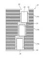
図4Aは、図3に示す挿入工程S1の説明図であり、図1および図2に示す回転子鉄心21の磁石挿入孔23の近傍の模式的な断面図である。挿入工程S1は、複数の段部21a,21b,21c(図4H参照)によって構成される回転子鉄心21のひとつの段部21aの磁石挿入孔23に永久磁石24を挿入する工程である。
(Insertion process)
FIG. 4A is an explanatory diagram of the insertion step S1 shown in FIG. 3, and is a schematic cross-sectional view near the
挿入工程S1では、まず、回転子鉄心21の軸線L方向の一端にエンドリング22を固定して、磁石挿入孔23の一端をエンドリング22によって閉塞する。次に、たとえば自動挿入機を用い、永久磁石24を把持して磁石挿入孔23に挿入する。これにより、図4Aに示すように、永久磁石24は、一端がエンドリング22によって閉鎖された段部21aの磁石挿入孔23内に配置される。この状態で、永久磁石24の外周面と磁石挿入孔23の内周面との間には、間隙が形成されている。
In the insertion step S1, first, the
挿入工程S1は、複数の磁石挿入孔23に対して順次行うことができる。しかし、生産性向上の観点からは、挿入工程S1において、複数の永久磁石24を複数の磁石挿入孔23に一括して挿入することが好ましい。永久磁石24の一括挿入は、たとえば複数の永久磁石24を把持して磁石挿入孔23に一括挿入する自動挿入機を用いて行うことができる。挿入工程S1の終了後は、図3に示すように、積層工程S2が実施される。
The insertion step S1 can be sequentially performed on the plurality of magnet insertion holes 23. However, from the viewpoint of improving productivity, it is preferable to insert the plurality of
(積層工程)
図4Bは、図3に示す積層工程S2の説明図である。積層工程S2は、回転子鉄心21が軸線L方向において多段に構成される段スキューの構成を有する場合に、下段の段部21aに上段の段部21bを、回転子鉄心21の周方向に所定のスキュー角ずらして積層させる工程である。積層工程S2によって積層された上段の段部21bの磁石挿入孔23の下部の開口は、永久磁石24が配置された下段の段部21aの磁石挿入孔23の上部の開口に連通している。積層工程S2の終了後は、図3に示すように、注入工程S3が実施される。
(Lamination process)
FIG. 4B is an explanatory diagram of the laminating step S2 shown in FIG. In the laminating step S2, when the
(注入工程)
図4Cは、図3に示す注入工程S3の説明図である。注入工程S3は、上段の段部21bの磁石挿入孔23に接着剤25を注入して、下段の段部21aの磁石挿入孔23に配置された下段の永久磁石24の少なくとも上端部の周囲に接着剤25を配置する工程である。
(Injection process)
FIG. 4C is an explanatory diagram of the implantation step S3 shown in FIG. In the injection step S3, the adhesive 25 is injected into the
注入工程S3では、たとえばディスペンサによって、積層工程S2によって積層された上段の段部21bの磁石挿入孔23の上部の開口から、上段の段部21bの磁石挿入孔23の底部に接着剤25を注入する。接着剤25としては、たとえばエポキシ系の接着剤を用いることができる。また、接着剤25の漏れを防止するために、粉体樹脂を混ぜ合わせた接着剤25を使用してもよい。
In the injection step S3, the adhesive 25 is injected into the bottom of the
接着剤25の粘度は、回転子鉄心21を構成する電磁鋼鈑への浸透を抑制する観点から、たとえば0.5Pa・s以上かつ80Pa・s以下の範囲で、できるだけ高粘度のものを用いることができる。また、接着剤25の粘度は、永久磁石24としてフェライト磁石を用いる場合には、たとえば15Pa・s以上かつ40Pa・s以下、永久磁石24としてネオジム磁石を用いる場合には、20Pa・s以上かつ45Pa・s以下であることが好ましい。すなわち、接着剤25の粘度は、15Pa・s以上かつ45Pa・s以下の範囲が好適である。
The viscosity of the adhesive 25 should be as high as possible within a range of, for example, 0.5 Pa · s or more and 80 Pa · s or less, from the viewpoint of suppressing penetration into the electromagnetic steel sheet constituting the
注入工程S3において、接着剤25の注入量は、たとえば以下の観点から決定することができる。1つには、後述する充填工程S4後に、接着剤25が磁石挿入孔23から溢れ出ることを防止することができる注入量という観点である。他には、後述する充填工程S4後に、下段の段部21aに配置された永久磁石24の外表面と、上段の段部21bに配置された永久磁石24の外表面が、可能な限り広い範囲で覆われる注入量という観点である。
In the injection step S3, the injection amount of the adhesive 25 can be determined, for example, from the following viewpoint. One is from the viewpoint of the injection amount that can prevent the adhesive 25 from overflowing from the
接着剤25の溢れを防止する観点からは、少なくとも上段の段部21bに配置される永久磁石24の押し込み方向における後端面24bが接着剤25から露出する量(図4Dを参照)に調整されることが好ましい。永久磁石24の外表面のより広い範囲を覆う観点からは、接着剤25の注入量は、たとえば次のように決定することができる。下段の段部21aの磁石挿入孔23の容積から永久磁石24の体積を引いた体積に、上段の段部21bの磁石挿入孔23の下端から永久磁石24の上端までの容積から永久磁石24の体積を引いた体積を加えた体積を、接着剤25の注入量とすることができる。
From the viewpoint of preventing the adhesive 25 from overflowing, at least the
なお、永久磁石24および磁石挿入孔23は、製造上の公差を有している。そのため、接着剤25の注入量は、公差の範囲で最小寸法の磁石挿入孔23に、公差の範囲で最大寸法の永久磁石24が挿入された場合を基準に調整されることが好ましい。これにより、接着剤25が磁石挿入孔23から溢れ出ることをより確実に防止することができ、接着剤25の使用量を最適化することができる。
The
注入工程S3は、複数の磁石挿入孔23に対して順次行うことができる。しかし、生産性向上および接着剤25の浸透防止の観点からは、注入工程S3において、複数の磁石挿入孔23に一括して接着剤25を注入することが好ましい。接着剤25の一括注入は、たとえば複数のノズルを備えたディスペンサによって行うことができる。注入工程S3の終了後は、図3に示すように、充填工程S4が実施される。 The injection step S3 can be sequentially performed on the plurality of magnet insertion holes 23. However, from the viewpoint of improving productivity and preventing the penetration of the adhesive 25, it is preferable that the adhesive 25 be injected into the plurality of magnet insertion holes 23 in a lump in the injection step S3. The batch injection of the adhesive 25 can be performed by, for example, a dispenser having a plurality of nozzles. After the end of the injection step S3, a filling step S4 is performed as shown in FIG.
(充填工程)
図4Dは、図3に示す充填工程S4の説明図である。充填工程S4は、上段の段部21bの磁石挿入孔23に上段の永久磁石24を押し込んで、接着剤25を下段の永久磁石24の外表面および上段の永久磁石24の外表面に行き渡らせる工程である。充填工程S4では、まず、上段の段部21bの磁石挿入孔23に上段の永久磁石24が、たとえば自動挿入機によって挿入される。これにより、上段の永久磁石24は、下部が接着剤25に接触した状態で上段の段部21bの磁石挿入孔23内に配置される。
(Filling process)
FIG. 4D is an explanatory diagram of the filling step S4 shown in FIG. In the filling step S4, a step of pushing the upper
しかし、回転子鉄心21を構成する積層された電磁鋼鈑間への接着剤25の浸透を抑制可能な比較的高い粘度の接着剤25が使用される。そのため、上段の段部21bの磁石挿入孔23に上段の永久磁石24を挿入しただけでは、永久磁石24の周囲に接着剤25が十分に行き渡っていない。また、上段の永久磁石24の下端と下段の永久磁石24の上端との間には、比較的粘度の高い接着剤25が存在し、比較的大きな間隔が形成されている。
However, a relatively high-
そのため、充填工程S4では、図4Dに示すように、上段の永久磁石24を上段の段部21bの磁石挿入孔23に押し込んで、接着剤25を上段の永久磁石24の外表面と下段の永久磁石24の外表面とに行き渡らせる。充填工程S4は、たとえば永久磁石24を押し込む力と距離を制御可能なシャフトSを用いて行うことができる。
Therefore, in the filling step S4, as shown in FIG. 4D, the upper
充填工程S4では、接着剤25が注入された上段の段部21bの磁石挿入孔23に上段の永久磁石24を圧入することで、上段の永久磁石24の下端と下段の永久磁石24の上端との間で接着剤25が加圧される。これにより、上段および下段の段部21a,21b磁石挿入孔23の側壁と、上段および下段の永久磁石24の側面との間の隙間に、接着剤25が充填され、上段および下段の永久磁石24の外表面のより広い範囲を接着剤25によって覆うことができる。
In the filling step S4, the lower end of the upper
より具体的には、上段の永久磁石24の押し込み方向における前端面24aから押し込み方向における後端面24bの近傍まで、接着剤25が上段の永久磁石24の外表面に行き渡る。そして、上段の永久磁石24の外表面のうち後端面24bとその近傍の微小な領域を除く概ね全周が接着剤25によって覆われて、磁石挿入孔23に固定される。また、下段の永久磁石24の上端から下端まで、接着剤25が永久磁石24の外表面に行き渡る。そして、下段の永久磁石24の外表面のうち下端面とその近傍の微小な領域を除く概ね全周が接着剤25によって覆われて、磁石挿入孔23に固定される。これにより、接着剤25の無駄をなくして、接着剤25の使用量を最小限に留めることができる。
More specifically, the adhesive 25 spreads over the outer surface of the upper
また、充填工程S4において、永久磁石24を押し込む力を制御することで、永久磁石24の損傷を防止することができ、永久磁石24を適切な位置まで押し込むことができる。また、充填工程S4において、永久磁石24を押し込む距離を制御することで、永久磁石24の損傷を防止することができ、永久磁石24を適切な位置まで押し込むことができる。
Further, in the filling step S4, by controlling the force for pushing the
充填工程S4は、複数の磁石挿入孔23に順次行うことができる。しかし、生産性向上および接着剤25の浸透防止の観点からは、充填工程S4において、複数の永久磁石24を複数の磁石挿入孔23に一括して押し込むことが好ましい。永久磁石24の一括押込みは、たとえば複数の永久磁石24を複数のシャフトSによって磁石挿入孔23に一括して圧入する自動圧入機を用いて行うことができる。
The filling step S4 can be sequentially performed on the plurality of magnet insertion holes 23. However, from the viewpoint of improving the productivity and preventing the penetration of the adhesive 25, it is preferable to collectively push the plurality of
なお、挿入工程S1、積層工程S2、注入工程S3、および充填工程S4は、図1に示す例のように、磁石挿入孔23に複数の永久磁石24が挿入される場合にも、図2に示す例のように、磁石挿入孔23に1つの永久磁石24が挿入される場合にも、同様に実施することができる。充填工程S4の終了後は、たとえば、図3に示すように挿入完了判定S5を実施することができる。
Note that the insertion step S1, the lamination step S2, the injection step S3, and the filling step S4 are performed in FIG. 2 even when a plurality of
(挿入完了判定)
挿入完了判定S5では、すべての磁石挿入孔23に永久磁石24が挿入されたか否かの判定を行う。たとえば、注入工程S3および充填工程S4を、個々の磁石挿入孔23に対して順次行う場合には、磁石挿入孔23の数と等しい回数の注入工程S3および充填工程S4が実施されたか否かを判定する。
(Insertion completion judgment)
In the insertion completion determination S5, it is determined whether or not the
判定の結果、各工程の実施回数が規定の回数に達していない場合(NO)には、図3に示すように、再度、注入工程S3および充填工程S4を実施する。一方、判定の結果、各工程の実施回数が規定の回数に達している場合(YES)には、積層完了判定S6を実施する。なお、すべての磁石挿入孔23に対して一括して注入工程S3および充填工程S4を実施する場合には、挿入完了判定S5を省略することができる。 As a result of the determination, if the number of executions of each step has not reached the prescribed number (NO), as shown in FIG. 3, the injection step S3 and the filling step S4 are performed again. On the other hand, if the result of the determination indicates that the number of times each step has been performed has reached the prescribed number (YES), a lamination completion determination S6 is performed. In addition, when performing the injection | pouring process S3 and the filling process S4 collectively with respect to all the magnet insertion holes 23, the insertion completion determination S5 can be omitted.
(積層完了判定)
積層完了判定S6では、回転子鉄心21を構成する複数の段部21a,21b,21c(図4Hを参照)の積層が完了したか否かの判定を行う。すなわち、回転子鉄心21が軸線L方向において多段に構成される段スキューの構成を有する場合に、回転子鉄心21を構成する段部21a,21b,21cを積層させる積層工程S2が完了したか否かを判定する。
(Lamination completion judgment)
In the lamination completion determination S6, it is determined whether or not the lamination of the plurality of
判定の結果、積層工程S2が未完了であれば(NO)、図3に示すように積層工程S2を実施する。また、判定の結果、積層工程S2が完了していれば(YES)、図3に示すように硬化工程S8と遠心充填工程S7、を実施する。なお、回転子鉄心21が多段の構成を有しない場合には、積層完了判定S6および積層工程S2を省略することができる。
As a result of the determination, if the lamination step S2 is not completed (NO), the lamination step S2 is performed as shown in FIG. If the result of determination is that lamination step S2 has been completed (YES), curing step S8 and centrifugal filling step S7 are performed as shown in FIG. When the
(2回目の積層工程)
図4Eは、図3に示す積層完了判定S6の後の2回目の積層工程S2の説明図である。2回目の積層工程S2では、1回目の積層工程S2と同様に、下段の段部21bに上段の段部21cを、回転子鉄心21の周方向に所定のスキュー角ずらして積層させる。積層工程S2によって積層された上段の段部21cの磁石挿入孔23の下部の開口は、永久磁石24が配置された下段の段部21bの磁石挿入孔23の上部の開口に連通している。2回目の積層工程S2の終了後は、図3に示すように、2回目の注入工程S3が実施される。
(Second lamination process)
FIG. 4E is an explanatory diagram of a second lamination step S2 after the lamination completion determination S6 shown in FIG. In the second laminating step S2, as in the first laminating step S2, the
(2回目の注入工程)
図4Fは、図3に示す積層完了判定S6の後の2回目の注入工程S3の説明図である。2回目の注入工程S3では、回転子鉄心21の下段の段部21bに積層された上段の段部21cの磁石挿入孔23に接着剤25を注入し、下段の段部21bの磁石挿入孔23に配置された下段の永久磁石24の上端部の周囲に接着剤25を配置する。これにより、下段の段部21bの磁石挿入孔23の上部と上段の段部21cの磁石挿入孔23の底部とに接着剤25が配置される。
(Second injection step)
FIG. 4F is an explanatory diagram of the second injection step S3 after the lamination completion determination S6 shown in FIG. In the second injection step S3, the adhesive 25 is injected into the
(2回目の充填工程)
図4Gは、図3に示す積層完了判定S6の後の2回目の充填工程の説明図である。2回目の充填工程S4では、1回目の充填工程S4と同様に、上段の段部21bの接着剤25が注入された磁石挿入孔23に永久磁石24を挿入する。この段階では、1回目の充填工程S4と同様に、下段の段部21bの磁石挿入孔23に配置された永久磁石24の周囲、および、上段の段部21cの磁石挿入孔23に配置された永久磁石24の周囲に接着剤25が十分に行き渡っていない。また、上段の永久磁石24の下端と下段の永久磁石24の上端との間には、比較的粘度の高い接着剤25が存在し、比較的大きな間隔が形成されている。
(Second filling process)
FIG. 4G is an explanatory diagram of a second filling step after the lamination completion determination S6 shown in FIG. In the second filling step S4, as in the first filling step S4, the
次に、1回目の充填工程S4と同様に、永久磁石24を上段の段部21cの磁石挿入孔23に押し込んで、接着剤25を上段と下段の永久磁石24の外表面に行き渡らせる。2回目の充填工程S4の完了後は、図3に示すように、再度、挿入完了判定S5および積層完了判定S6を行い、所定の段数の段部21cを積層させ(図4Hを参照)、各段部21cに注入工程S3および充填工程S4を実施する。
Next, similarly to the first filling step S4, the
このように、本実施形態の回転電機の製造方法S100では、積層工程S2と注入工程S3と充填工程S4とを繰り返すことができる。これにより、所望の段数の段部21a,21b,21cを有する回転子鉄心21を製作することができる。なお、最上段の段部21cに対する接着剤25の注入量は、他の段部21a,21bに対する接着剤25の注入量よりも多くしてもよい。これにより、最上段の永久磁石24の外表面のより広い範囲を覆うことができるだけでなく、後述する遠心充填工程S7によって、最下段の永久磁石24においても外表面のより広い範囲を覆うことが可能になる。
Thus, in the rotating electric machine manufacturing method S100 of the present embodiment, the laminating step S2, the pouring step S3, and the filling step S4 can be repeated. Thereby, the
所定の回数の積層工程S2が実施されて所定の段数の段部21a,21b,21cが積層され、各々の段部21a,21b,21cに注入工程S3および充填工程S4が実施され、積層完了判定S6において所定の段数の段部21a,21b,21cが積層されたことが判定されると(YES)、図3に示すように、遠心充填工程S7および硬化工程S8が実施される。
A predetermined number of stacking steps S2 are performed to stack a predetermined number of
(遠心充填工程および硬化工程)
図4Hは、図3に示す硬化工程S8および遠心充填工程S7の説明図である。充填工程S4の完了後、硬化工程S8および遠心充填工程S7の前に、複数の段部21a,21b,21cによって構成された回転子鉄心21にエンドリング22が接合され、最上段の段部21cの磁石挿入孔23の開口が閉鎖される。
(Centrifugal filling process and curing process)
FIG. 4H is an explanatory diagram of the curing step S8 and the centrifugal filling step S7 shown in FIG. After the filling step S4 is completed, and before the curing step S8 and the centrifugal filling step S7, the
遠心充填工程S7は、充填工程S4の終了後に、回転子鉄心21を軸周りに回転させて接着剤25を永久磁石24と回転子鉄心21との間に行き渡らせる工程である。硬化工程S8は、たとえば熱硬化性樹脂からなる接着剤25を加熱したり、紫外線硬化性樹脂からなる接着剤25に紫外線を照射したりして、接着剤25を硬化させる工程である。
The centrifugal filling step S7 is a step in which after the filling step S4, the
なお、硬化工程S8は、遠心充填工程S7の終了後に行ってもよいが、図3に示すように、遠心充填工程S7と硬化工程S8とを並行して行うことができる。これにより、接着剤25を永久磁石24と回転子鉄心21との間に行き渡らせながら硬化させることができ、アンバランス量を最小化することができる。また、2つの工程を並行して行うことで、生産性を向上させることができる。遠心充填工程S7および硬化工程S8の終了後は、図3に示すように、調整工程S9を実施する。
The curing step S8 may be performed after the completion of the centrifugal filling step S7, but as shown in FIG. 3, the centrifugal filling step S7 and the curing step S8 can be performed in parallel. Thereby, the adhesive 25 can be hardened while spreading between the
(調整工程)
調整工程S9は、硬化工程S8が終了した回転子20のバランス調整を行う工程である。具体的には、たとえば不図示のバランスウェイトを調整することで、回転子20のバランス調整を行うことができる。調整工程S9の終了後は、図3に示すように着磁工程S10を実施する。
(Adjustment process)
The adjusting step S9 is a step of adjusting the balance of the
(着磁工程)
着磁工程S10は、永久磁石24の着磁を行う工程である。着磁工程S10は、適宜の着磁装置によって行うことができる。なお、予め着磁した永久磁石24を用いる場合には、図3に示す着磁工程S10を省略することができる。また、本実施形態の回転電機の製造方法S100は、図3に示す各工程以外の工程については、公知の回転電機の製造方法と同様の工程を採用することができる。
(Magnetization process)
The magnetizing step S10 is a step of magnetizing the
以上説明したように、本実施形態の回転電機の製造方法S100は、挿入工程S1と、積層工程S2と、注入工程S3と、充填工程S4とを有している。そのため、挿入工程S1で、回転子鉄心21の最下段の段部21aの磁石挿入孔23に永久磁石24を配置し、積層工程S2で下段の段部21aの磁石挿入孔23の上部に上段の段部21bの磁石挿入孔23が配置される。
As described above, the rotating electric machine manufacturing method S100 of the present embodiment includes the insertion step S1, the lamination step S2, the injection step S3, and the filling step S4. For this reason, in the insertion step S1, the
そして、注入工程S3で、上段の段部21bの磁石挿入孔23の上方の開口から接着剤を注入し、下段の段部21aの磁石挿入孔23に挿入された永久磁石24の上端部の周囲に接着剤25を配置することができる。これにより、下段の段部21aの磁石挿入孔23の上方の開口に、回転子鉄心21の電磁鋼鈑間への浸透を抑制可能な比較的粘度の高い接着剤を注入した場合でも、上段の段部21bの磁石挿入孔23によって接着剤25の溢れを防止できる。
Then, in the injection step S3, an adhesive is injected from the opening above the
さらに、充填工程S4で、永久磁石24を上段の段部21bの磁石挿入孔23に押し込んで、接着剤25を下段の段部21aの永久磁石24の外表面と、上段の段部21bの永久磁石24の外表面とに行き渡らせることができる。
Further, in the filling step S4, the
したがって、本実施形態の回転電機の製造方法S100によれば、回転子鉄心21に埋め込まれる永久磁石24の外表面のより広い範囲を接着剤25によって覆うことができ、回転子鉄心21の高速回転時に永久磁石24に作用する応力を緩和することができる。そのため、たとえば、ハイブリッド自動車や電気自動車等の車両に搭載される回転電機100の高速回転化および高出力化を可能にすることができる。
Therefore, according to the rotating electric machine manufacturing method S100 of the present embodiment, a wider area of the outer surface of the
さらに、本実施形態の回転電機の製造方法S100によれば、挿入工程S1および積層工程S2の後に、注入工程S3および充填工程S4を行うことで、固化前の接着剤25が回転子鉄心21に接触する時間を短縮することができる。これにより、回転子鉄心21を構成する電磁鋼鈑間への接着剤25の浸透を抑制することができる。
Furthermore, according to the rotating electric machine manufacturing method S100 of the present embodiment, the injection step S3 and the filling step S4 are performed after the insertion step S1 and the lamination step S2, so that the adhesive 25 before solidification is applied to the
また、予め永久磁石24が挿入された下段の段部21a(21b)の磁石挿入孔23に、上段の段部21b(21c)の磁石挿入孔23を介して接着剤25を注入することで、接着剤25が溢れるのを防止することができる。したがって、上述のように比較的粘度の高い接着剤25を使用することができ、回転子鉄心21を構成する電磁鋼鈑間への接着剤25の浸透をより効果的に抑制することができる。
Further, by injecting the adhesive 25 into the
図5は、前述の実施形態に係る回転電機の製造方法S100によって製造された回転電機100を搭載する四輪駆動を前提としたハイブリッド自動車のパワートレインの概略構成図である。
FIG. 5 is a schematic configuration diagram of a power train of a hybrid vehicle on which four-wheel drive is mounted on which the rotating
ハイブリッド自動車は、前輪側の主動力として、エンジンENGと回転電機100を有する。前輪側の動力源である回転電機100は、エンジンENGと変速機TRの間に配置されている。エンジンENGと回転電機100の動力は、変速機TRにより変速され、前輪側駆動輪FWに動力を伝えられる。
The hybrid vehicle has an engine ENG and a rotating
後輪側の駆動力源である回転電機100は、前輪側の動力源である回転電機100と同様のものを用いることもできるし、他の一般的な構成の回転電機を用いることもできる。また、後輪の駆動においては、後輪側に配置された回転電機100と後輪側駆動輪RWが機械的に接続され、回転電機100の動力が後輪側駆動輪RWに伝達される。
The rotating
回転電機100は、エンジンENGの始動を行い、また、車両の走行状態に応じて、駆動力の発生と、車両減速時のエネルギーを電気エネルギーとして回収する発電力の発生を切り換える。回転電機100の駆動および発電動作は、車両の運転状況に合わせ、トルクおよび回転数が最適になるように電力変換装置INVにより制御される。
The rotating
回転電機100の駆動に必要な電力は、電力変換装置INVを介してバッテリBATから供給される。また、回転電機100が発電動作を行うときは、電力変換装置INVを介してバッテリBATに電気エネルギーが充電される。
Power required for driving the rotating
前述の本実施形態の回転電機の製造方法S100によれば、このような車両に搭載される回転電機100において、渦電流を低減し、モータ効率を向上させ、高速回転化を可能にすることができる。なお、回転電機100は、四輪駆動式以外のハイブリッド方式の車両においても勿論適用可能である。
According to the rotating electrical machine manufacturing method S100 of the present embodiment described above, in the rotating
以上、図面を用いて本発明の実施の形態を詳述してきたが、具体的な構成はこの実施形態に限定されるものではなく、本発明の要旨を逸脱しない範囲における設計変更等があっても、それらは本発明に含まれるものである。 As described above, the embodiment of the present invention has been described in detail with reference to the drawings. However, the specific configuration is not limited to this embodiment, and there are design changes and the like without departing from the gist of the present invention. They are also included in the present invention.
たとえば、前述の実施形態に係る回転電機の製造方法においては、製造される回転機の固定子のコイルが波巻きの分布巻きである例について説明した。しかし、本発明に係る回転電機の製造方法は、回転子の製造方法に特徴を有するため、固定子の構成は特に限定されない。すなわち、固定子のコイルは、重ね巻方式や集中巻き方式でもよい。また、製造される回転電機が内転型である例について説明したが、外転型の回転電機を製造する場合にも、本発明に係る回転電機の製造方法を適用することができる。 For example, in the method of manufacturing a rotating electric machine according to the above-described embodiment, an example has been described in which the stator coil of the manufactured rotating machine has a distributed winding of wave winding. However, the method for manufacturing a rotating electric machine according to the present invention is characterized by the method for manufacturing a rotor, and thus the configuration of the stator is not particularly limited. That is, the coils of the stator may be of a lap winding type or a concentrated winding type. Further, the example in which the rotating electric machine to be manufactured is of the internal rotation type has been described, but the manufacturing method of the rotating electric machine according to the present invention can also be applied to the case of manufacturing the external rotation type rotating electric machine.
また、前述の実施形態に係る回転電機の製造方法によって製造される回転電機の適用例として、電気自動車やハイブリット電気自動車を例に挙げて説明した。しかし、前述の実施形態に係る回転電機の製造方法によって製造される回転電機は、オルタネータ、スタータジェネレータ(モータジェネレータ含む)、電動コンプレッサ用、電動ポンプ用等の自動車用補機モータは当然の事として、エレベータ用等の産業用、エアコン圧縮機等の家電用モータへの適用も可能である。 In addition, as an application example of the rotating electric machine manufactured by the method for manufacturing a rotating electric machine according to the above-described embodiment, an electric vehicle or a hybrid electric vehicle has been described as an example. However, the rotating electric machine manufactured by the method for manufacturing a rotating electric machine according to the above-described embodiment includes, as a matter of course, auxiliary motors for automobiles such as an alternator, a starter generator (including a motor generator), an electric compressor, and an electric pump. It can also be applied to industrial motors such as elevators, and motors for home appliances such as air conditioner compressors.
21…回転子鉄心、21a…段部、21b…段部、21c…段部、22…エンドリング、23…磁石挿入孔、24…永久磁石、24b…後端面、25…接着剤、25a…接着剤層、100…回転電機、S1…挿入工程、S2…積層工程、S3…注入工程、S4…充填工程、S7…遠心充填工程、S8…硬化工程、S100…回転電機の製造方法 Reference numeral 21: rotor core, 21a: step, 21b: step, 21c: step, 22: end ring, 23: magnet insertion hole, 24: permanent magnet, 24b: rear end face, 25: adhesive, 25a: adhesion Agent layer, 100: rotating electric machine, S1: insertion step, S2: laminating step, S3: pouring step, S4: filling step, S7: centrifugal filling step, S8: curing step, S100: method of manufacturing rotating electric machine
Claims (9)
前記複数の永久磁石の挿入方向の高さは、前記複数の段部の挿入方向の高さに対して、小さく設定されており、
前記複数の段部のうちの下段の段部に下段用の永久磁石を挿入する挿入工程と、
前記下段の段部の上に、上段の段部を周方向にずらして前記複数の鋼板を積層させる積層工程と、
前記上段の段部に接着剤を注入して前記下段の段部に配置された前記下段用の永久磁石の少なくとも上端部の周囲に該接着剤を配置する注入工程と、
前記上段の段部に上段用の永久磁石を押し込んで前記上段用の永久磁石の挿入方向の先端面を前記下段の段部と前記上段の段部との間の段差面に当接させ、前記接着剤を前記下段用の永久磁石の外表面および該上段用の永久磁石の外表面に行き渡らせる充填工程と、を有することを特徴とする回転電機の製造方法。 A method for manufacturing a rotating electric machine in which a plurality of steel plates are laminated, and a plurality of permanent magnets are inserted into each of the plurality of steps in the magnet insertion holes of the rotor core in which a magnet insertion hole having a plurality of steps is formed. So,
The height of the plurality of permanent magnets in the insertion direction is smaller than the height of the plurality of steps in the insertion direction,
An insertion step of inserting a permanent magnet for a lower step into a lower step of the plurality of steps,
On the lower step portion, and a laminating step of laminating the plurality of steel plates by shifting the upper stepped portion in the circumferential direction,
An injection step of disposing the adhesive around at least the upper end portion of the permanent magnet for the lower that by injecting an adhesive disposed on the step portion of the lower step portion of the upper stage,
The insertion direction of the distal end surface of the permanent magnet for the push the permanent magnets for the upper upper step portion of the upper is brought into contact with the stepped surface between the stepped portion of the upper and the lower step portion, said method of manufacturing a rotary electric machine, characterized in that it comprises a filling step to spread the adhesive on the outer surface and an outer surface of the permanent magnet for the upper permanent magnet for the lower, the.
前記注入工程において、前記複数の段部を有する複数の前記磁石挿入孔に一括して前記接着剤を注入し、
前記充填工程において、複数の前記上段用の永久磁石を前記複数の段部を有する複数の前記磁石挿入孔に一括して押し込むことを特徴とする請求項1から請求項3のいずれか一項に記載の回転電機の製造方法。 In the inserting step, the permanent magnet for the lower stage is inserted collectively into the plurality of magnet insertion holes having the plurality of steps ,
In the injecting step, the adhesive is collectively injected into the plurality of magnet insertion holes having the plurality of steps ,
In the filling step, in any one of claims 1 to 3, characterized in that pushed collectively permanent magnet for a plurality of the upper to the plurality of the magnet insertion holes having a plurality of stepped portions The manufacturing method of the rotating electric machine according to the above.
Priority Applications (1)
| Application Number | Priority Date | Filing Date | Title |
|---|---|---|---|
| JP2016136216A JP6626794B2 (en) | 2016-07-08 | 2016-07-08 | Method of manufacturing rotating electric machine |
Applications Claiming Priority (1)
| Application Number | Priority Date | Filing Date | Title |
|---|---|---|---|
| JP2016136216A JP6626794B2 (en) | 2016-07-08 | 2016-07-08 | Method of manufacturing rotating electric machine |
Publications (2)
| Publication Number | Publication Date |
|---|---|
| JP2018007528A JP2018007528A (en) | 2018-01-11 |
| JP6626794B2 true JP6626794B2 (en) | 2019-12-25 |
Family
ID=60948219
Family Applications (1)
| Application Number | Title | Priority Date | Filing Date |
|---|---|---|---|
| JP2016136216A Active JP6626794B2 (en) | 2016-07-08 | 2016-07-08 | Method of manufacturing rotating electric machine |
Country Status (1)
| Country | Link |
|---|---|
| JP (1) | JP6626794B2 (en) |
Families Citing this family (1)
| Publication number | Priority date | Publication date | Assignee | Title |
|---|---|---|---|---|
| JP7128730B2 (en) * | 2018-11-30 | 2022-08-31 | 東芝産業機器システム株式会社 | Adhesive application device and adhesive application method |
Family Cites Families (6)
| Publication number | Priority date | Publication date | Assignee | Title |
|---|---|---|---|---|
| JPH09327140A (en) * | 1996-06-07 | 1997-12-16 | Hitachi Ltd | Electric rotating machine of permanent magnet rotation type and its manufacture |
| JP4453427B2 (en) * | 2004-04-15 | 2010-04-21 | トヨタ自動車株式会社 | Rotor for permanent magnet motor and method for manufacturing the same |
| JP5322700B2 (en) * | 2009-02-27 | 2013-10-23 | 三菱電機株式会社 | Rotor, manufacturing method thereof, manufacturing apparatus thereof, and compressor equipped with the rotor |
| JP5325712B2 (en) * | 2009-09-02 | 2013-10-23 | 日立オートモティブシステムズ株式会社 | Rotating electric machine and manufacturing method thereof |
| JP2011254619A (en) * | 2010-06-02 | 2011-12-15 | Miyaden Co Ltd | Rotor heating apparatus and rotor heating method for permanent magnet motor |
| JP6401486B2 (en) * | 2014-04-14 | 2018-10-10 | 株式会社三井ハイテック | Rotor laminated iron core and method for producing rotor laminated iron core |
-
2016
- 2016-07-08 JP JP2016136216A patent/JP6626794B2/en active Active
Also Published As
| Publication number | Publication date |
|---|---|
| JP2018007528A (en) | 2018-01-11 |
Similar Documents
| Publication | Publication Date | Title |
|---|---|---|
| US10840755B2 (en) | Electric machine with q-offset grooved interior-magnet rotor and vehicle | |
| JP5479978B2 (en) | Rotating electric machine | |
| JP3746372B2 (en) | Permanent magnet type rotating electric machine and electric vehicle using the same | |
| JP5961344B2 (en) | Magnetic flux concentrating type synchronous rotating electrical machine with permanent magnet | |
| EP3514921B1 (en) | Dynamo-electric machine | |
| WO2015146210A1 (en) | Permanent magnet rotating electric machine and method for manufacturing same | |
| US20090278417A1 (en) | IPM Rotor, IPM Rotor Manufacturing Method and IPM Rotor Manufacturing Apparatus | |
| CN108475972B (en) | Rotor, magnetizing method, motor, and scroll compressor | |
| CN108616176A (en) | The rotor structure of WRSM motor | |
| JP5665660B2 (en) | Permanent magnet rotating electric machine | |
| JP6661939B2 (en) | Rotor | |
| JP7293371B2 (en) | Rotor of rotary electric machine | |
| JP2009195088A (en) | Rotating electric machine and manufacturing method thereof | |
| CN112953054A (en) | Electric machine with noise-reducing rotor recess | |
| JP2019154232A (en) | Rotor and dynamo-electric machine | |
| US20140265702A1 (en) | Electric Machine with Skewed Permanent Magnet Arrangement | |
| US10720807B2 (en) | Magnet-type rotor, rotary electric machine equipped with magnet-type rotor, and electric vehicle equipped with rotary electric machine | |
| JP6626794B2 (en) | Method of manufacturing rotating electric machine | |
| US11637467B2 (en) | Adhesive mixture including hard magnetic material for e-machine rotor | |
| JP6615708B2 (en) | Manufacturing method of rotating electrical machine | |
| JP2018042371A (en) | Brushless motor | |
| WO2019187205A1 (en) | Rotary electric machine | |
| JP2000152538A (en) | Motor with embedded permanent magnet | |
| JP2004140951A (en) | Permanent magnet-embedded motor | |
| KR20170060501A (en) | Rotor for Wound Rotor Synchronous Motor |
Legal Events
| Date | Code | Title | Description |
|---|---|---|---|
| A621 | Written request for application examination |
Free format text: JAPANESE INTERMEDIATE CODE: A621 Effective date: 20180704 |
|
| A977 | Report on retrieval |
Free format text: JAPANESE INTERMEDIATE CODE: A971007 Effective date: 20190409 |
|
| A131 | Notification of reasons for refusal |
Free format text: JAPANESE INTERMEDIATE CODE: A131 Effective date: 20190508 |
|
| A521 | Request for written amendment filed |
Free format text: JAPANESE INTERMEDIATE CODE: A523 Effective date: 20190614 |
|
| TRDD | Decision of grant or rejection written | ||
| A01 | Written decision to grant a patent or to grant a registration (utility model) |
Free format text: JAPANESE INTERMEDIATE CODE: A01 Effective date: 20191119 |
|
| A61 | First payment of annual fees (during grant procedure) |
Free format text: JAPANESE INTERMEDIATE CODE: A61 Effective date: 20191202 |
|
| R150 | Certificate of patent or registration of utility model |
Ref document number: 6626794 Country of ref document: JP Free format text: JAPANESE INTERMEDIATE CODE: R150 |
|
| S533 | Written request for registration of change of name |
Free format text: JAPANESE INTERMEDIATE CODE: R313533 |
|
| R350 | Written notification of registration of transfer |
Free format text: JAPANESE INTERMEDIATE CODE: R350 |
|
| R250 | Receipt of annual fees |
Free format text: JAPANESE INTERMEDIATE CODE: R250 |