EP3276249B1 - Leuchtsystem für beleuchtungsvorrichtung und optional für signalvorrichtung für kraftfahrzeug - Google Patents
Leuchtsystem für beleuchtungsvorrichtung und optional für signalvorrichtung für kraftfahrzeug Download PDFInfo
- Publication number
- EP3276249B1 EP3276249B1 EP17181259.7A EP17181259A EP3276249B1 EP 3276249 B1 EP3276249 B1 EP 3276249B1 EP 17181259 A EP17181259 A EP 17181259A EP 3276249 B1 EP3276249 B1 EP 3276249B1
- Authority
- EP
- European Patent Office
- Prior art keywords
- light
- luminous
- module
- segments
- cut
- Prior art date
- Legal status (The legal status is an assumption and is not a legal conclusion. Google has not performed a legal analysis and makes no representation as to the accuracy of the status listed.)
- Active
Links
Images

Classifications
-
- F—MECHANICAL ENGINEERING; LIGHTING; HEATING; WEAPONS; BLASTING
- F21—LIGHTING
- F21V—FUNCTIONAL FEATURES OR DETAILS OF LIGHTING DEVICES OR SYSTEMS THEREOF; STRUCTURAL COMBINATIONS OF LIGHTING DEVICES WITH OTHER ARTICLES, NOT OTHERWISE PROVIDED FOR
- F21V19/00—Fastening of light sources or lamp holders
- F21V19/001—Fastening of light sources or lamp holders the light sources being semiconductors devices, e.g. LEDs
-
- F—MECHANICAL ENGINEERING; LIGHTING; HEATING; WEAPONS; BLASTING
- F21—LIGHTING
- F21S—NON-PORTABLE LIGHTING DEVICES; SYSTEMS THEREOF; VEHICLE LIGHTING DEVICES SPECIALLY ADAPTED FOR VEHICLE EXTERIORS
- F21S45/00—Arrangements within vehicle lighting devices specially adapted for vehicle exteriors, for purposes other than emission or distribution of light
- F21S45/40—Cooling of lighting devices
- F21S45/47—Passive cooling, e.g. using fins, thermal conductive elements or openings
-
- F—MECHANICAL ENGINEERING; LIGHTING; HEATING; WEAPONS; BLASTING
- F21—LIGHTING
- F21S—NON-PORTABLE LIGHTING DEVICES; SYSTEMS THEREOF; VEHICLE LIGHTING DEVICES SPECIALLY ADAPTED FOR VEHICLE EXTERIORS
- F21S41/00—Illuminating devices specially adapted for vehicle exteriors, e.g. headlamps
- F21S41/10—Illuminating devices specially adapted for vehicle exteriors, e.g. headlamps characterised by the light source
- F21S41/14—Illuminating devices specially adapted for vehicle exteriors, e.g. headlamps characterised by the light source characterised by the type of light source
- F21S41/141—Light emitting diodes [LED]
- F21S41/143—Light emitting diodes [LED] the main emission direction of the LED being parallel to the optical axis of the illuminating device
-
- F—MECHANICAL ENGINEERING; LIGHTING; HEATING; WEAPONS; BLASTING
- F21—LIGHTING
- F21S—NON-PORTABLE LIGHTING DEVICES; SYSTEMS THEREOF; VEHICLE LIGHTING DEVICES SPECIALLY ADAPTED FOR VEHICLE EXTERIORS
- F21S41/00—Illuminating devices specially adapted for vehicle exteriors, e.g. headlamps
- F21S41/10—Illuminating devices specially adapted for vehicle exteriors, e.g. headlamps characterised by the light source
- F21S41/14—Illuminating devices specially adapted for vehicle exteriors, e.g. headlamps characterised by the light source characterised by the type of light source
- F21S41/141—Light emitting diodes [LED]
- F21S41/147—Light emitting diodes [LED] the main emission direction of the LED being angled to the optical axis of the illuminating device
-
- F—MECHANICAL ENGINEERING; LIGHTING; HEATING; WEAPONS; BLASTING
- F21—LIGHTING
- F21S—NON-PORTABLE LIGHTING DEVICES; SYSTEMS THEREOF; VEHICLE LIGHTING DEVICES SPECIALLY ADAPTED FOR VEHICLE EXTERIORS
- F21S41/00—Illuminating devices specially adapted for vehicle exteriors, e.g. headlamps
- F21S41/20—Illuminating devices specially adapted for vehicle exteriors, e.g. headlamps characterised by refractors, transparent cover plates, light guides or filters
- F21S41/24—Light guides
-
- F—MECHANICAL ENGINEERING; LIGHTING; HEATING; WEAPONS; BLASTING
- F21—LIGHTING
- F21S—NON-PORTABLE LIGHTING DEVICES; SYSTEMS THEREOF; VEHICLE LIGHTING DEVICES SPECIALLY ADAPTED FOR VEHICLE EXTERIORS
- F21S41/00—Illuminating devices specially adapted for vehicle exteriors, e.g. headlamps
- F21S41/20—Illuminating devices specially adapted for vehicle exteriors, e.g. headlamps characterised by refractors, transparent cover plates, light guides or filters
- F21S41/25—Projection lenses
- F21S41/255—Lenses with a front view of circular or truncated circular outline
-
- F—MECHANICAL ENGINEERING; LIGHTING; HEATING; WEAPONS; BLASTING
- F21—LIGHTING
- F21S—NON-PORTABLE LIGHTING DEVICES; SYSTEMS THEREOF; VEHICLE LIGHTING DEVICES SPECIALLY ADAPTED FOR VEHICLE EXTERIORS
- F21S41/00—Illuminating devices specially adapted for vehicle exteriors, e.g. headlamps
- F21S41/40—Illuminating devices specially adapted for vehicle exteriors, e.g. headlamps characterised by screens, non-reflecting members, light-shielding members or fixed shades
-
- F—MECHANICAL ENGINEERING; LIGHTING; HEATING; WEAPONS; BLASTING
- F21—LIGHTING
- F21S—NON-PORTABLE LIGHTING DEVICES; SYSTEMS THEREOF; VEHICLE LIGHTING DEVICES SPECIALLY ADAPTED FOR VEHICLE EXTERIORS
- F21S41/00—Illuminating devices specially adapted for vehicle exteriors, e.g. headlamps
- F21S41/60—Illuminating devices specially adapted for vehicle exteriors, e.g. headlamps characterised by a variable light distribution
- F21S41/65—Illuminating devices specially adapted for vehicle exteriors, e.g. headlamps characterised by a variable light distribution by acting on light sources
- F21S41/663—Illuminating devices specially adapted for vehicle exteriors, e.g. headlamps characterised by a variable light distribution by acting on light sources by switching light sources
-
- F—MECHANICAL ENGINEERING; LIGHTING; HEATING; WEAPONS; BLASTING
- F21—LIGHTING
- F21V—FUNCTIONAL FEATURES OR DETAILS OF LIGHTING DEVICES OR SYSTEMS THEREOF; STRUCTURAL COMBINATIONS OF LIGHTING DEVICES WITH OTHER ARTICLES, NOT OTHERWISE PROVIDED FOR
- F21V23/00—Arrangement of electric circuit elements in or on lighting devices
- F21V23/003—Arrangement of electric circuit elements in or on lighting devices the elements being electronics drivers or controllers for operating the light source, e.g. for a LED array
-
- F—MECHANICAL ENGINEERING; LIGHTING; HEATING; WEAPONS; BLASTING
- F21—LIGHTING
- F21S—NON-PORTABLE LIGHTING DEVICES; SYSTEMS THEREOF; VEHICLE LIGHTING DEVICES SPECIALLY ADAPTED FOR VEHICLE EXTERIORS
- F21S41/00—Illuminating devices specially adapted for vehicle exteriors, e.g. headlamps
- F21S41/30—Illuminating devices specially adapted for vehicle exteriors, e.g. headlamps characterised by reflectors
- F21S41/32—Optical layout thereof
- F21S41/36—Combinations of two or more separate reflectors
- F21S41/365—Combinations of two or more separate reflectors successively reflecting the light
Definitions
- the invention relates to the field of lighting and, optionally, signaling, in particular for motor vehicles. More particularly, the invention relates to a lighting and, optionally, signaling system for a motor vehicle.
- a motor vehicle is generally equipped with headlights intended to illuminate the road in front of the vehicle, at night or when the light is reduced.
- These headlights generally provide two distinct types of lighting: a first dipped-beam type lighting and a second main-beam type lighting.
- the dipped-beam type lighting provides sufficient lighting of the road in front of the vehicle to be able to travel safely without dazzling other road users.
- the main-beam type lighting provides lighting of a large portion of the road far in front of the vehicle.
- These types of lighting are generally subject to regulations defining, for example, geographical areas in which the light beam providing this type of lighting must comply with minimum and/or maximum light intensities. DE 10 2007 008 994 A1 shows such a bright spotlight.
- Light modules are known which make it possible to form both a regulatory dipped beam type lighting and a road type lighting consisting of several light segments. Each light segment of the road type lighting can be selectively switched off when it is likely to dazzle a road user, whose presence is detected by a detection system. These light modules therefore make it possible to achieve a selective road lighting function, also called “Glare Free High Beam”, or in French “Anti-glare road”, offering the driver better visibility of the road, while not disturbing other users.
- These selective road lighting and dynamic cornering lighting functions belong to a family of functions called adaptive lighting and/or signaling functions aimed at providing road lighting or vehicle signaling services which adapt to traffic conditions, the vehicle's environment and the behavior of road users.
- An aim of the invention is therefore to provide a lighting system which makes it possible to achieve both regulatory lighting and an adaptive function, and which is simple to achieve and inexpensive.
- the invention provides a lighting system for a lighting device and, optionally, a signaling device for a motor vehicle according to claim 1.
- the light power that the lighting system must provide is shared between two light modules, which makes it possible to reduce the number of high-power light emitting sources in each of the light modules, while allowing the system to achieve both regulatory lighting and an adaptive function.
- the light modules used are therefore simpler to design and less expensive.
- each light segment has at least 3 edges, including a lower edge and two lateral edges extending on either side of the lower edge.
- each light segment has a quadrilateral shape, in particular a rectangle or a trapezoid or a diamond.
- each light segment has a triangular shape.
- the edges may be sharp and the lower edge may be blurred.
- each light segment may have a light distribution such that the light intensity of the segment is maximum at the lower edge and decreases as one moves away from the lower edge.
- each light segment may have three edges, including a straight lower edge, a straight lateral edge and a curved edge joining the lower and lateral edges.
- each light module of the lighting system is arranged to form a first beam participating in the production of regulatory road-type lighting.
- each light module is arranged to form a first beam, called the lower beam, participating in the production of dipped beam type lighting and a second beam, called the upper beam, participating in the production of road type lighting; the first and second beams formed by each light module being selectively activatable.
- at least one of the light modules comprises light emitting means arranged to form at least two light segments selectively activatable in one of the first and second beams formed by this light module.
- at least the first light module is arranged so that the second beam formed by this first light module forms only a portion of regulatory road type lighting, and the light modules are arranged so that the second beams, when activated together, form regulatory road type lighting.
- each light module of the lighting system is arranged to form a first beam participating in the production of regulatory lighting of the dipped beam type.
- each light module is arranged to form a first beam, called the lower beam, participating in the production of dipped beam lighting and a second beam, called the upper beam, participating in the production of road lighting; the first and second beams formed by each light module being selectively activatable.
- at least one of the light modules comprises light emission means arranged to form at least two light segments selectively activatable in one of the first and second beams formed by this light module.
- at least the first light module is arranged so that the first beam formed by this first light module forms only a portion of regulatory dipped beam lighting, and the light modules are arranged so that the first beams, when activated together, form regulatory dipped beam lighting.
- the first and second light modules comprise light emission means arranged to form at least two light segments which can be selectively activated in the second beam formed by this light module.
- the first and/or the second light module comprises light emission means arranged to form at least two light segments that can be selectively activated in the first beam formed by this light module.
- the first and/or the second light module comprise light emission means arranged to form at least two light segments that can be selectively activated in the first beam formed by this light module and light emission means arranged to form at least two light segments that can be selectively activated in the second beam formed by this light module.
- the two light modules comprise light emission means arranged to form at least two light segments that can be selectively activated in one and/or the other of the first and second beams formed by these light modules.
- each of the two light modules comprises light emission means arranged to form at least two light segments which can be selectively activated in each of the second beams formed by these light modules.
- each of the two light modules comprises light emission means arranged to form at least two light segments that can be selectively activated in each of the first beams formed by these light modules.
- At least one of the light modules comprises light-emitting means arranged to form at least two light segments that can be selectively activated in one of the first and second beams formed by this light module and at least the other of the light modules comprises light emitting means arranged to form at least two light segments selectively activatable in the other of the first and second beams formed by this light module.
- each of the two light modules comprises light emission means arranged to form at least two light segments which can be selectively activated in the first beam and in the second beam formed by these light modules.
- the light emission means of each of the light modules are arranged so that the light segments formed by the emission means of the first light module are interlaced with the light segments formed by the emission means of the second light module when they are activated simultaneously.
- Interlaced light segments means segments arranged so that at least one light segment formed by the emission means of the first light module, called the first light segment, is arranged between two light segments formed by the emission means of the second light module, called the second segments.
- the light emitting means of each of the light modules are arranged such that the light segments formed by the emitting means of the first light module are juxtaposed and/or superimposed with the light segments formed by the emitting means of the second light module.
- the term "juxtaposed light segments” means light segments arranged adjacently, in particular such that, for two neighboring segments, only one of the edges of one light segment is in contact with one of the edges of the other light segment. These two light segments may be formed by a single light module or else, one of the segments is a first segment formed by the first light module and the other of the segments is a second segment formed by the second light module.
- juxtaposed light segments means: “superimposed light segments” light segments arranged such that, for two adjacent segments, a portion of one light segment is at least partially covered by a portion of the other light segment. These two light segments may be formed by a single light module or, one of the segments is a first segment formed by the first light module and the other of the segments is a second segment formed by the second light module. In particular, a fraction, in particular half, of the surface of a first light segment may be covered by an identical fraction, in particular half of the surface of a second light segment.
- the light segments are interlaced according to an alternation of at least a first segment formed by the first light module and at least a second segment formed by the second light module. It will thus be possible to provide an alternation between a segment coming from one of the light modules and a segment coming from the other light module, or an alternation between two segments coming from one of the light modules and a segment coming from the other light module, or an alternation between two segments coming from one of the light modules and two segments coming from the other light module.
- the light emitting means of a light module are arranged such that at least two consecutive selectively activatable light segments are juxtaposed. In one exemplary embodiment, the light emitting means of said light module are arranged such that all consecutive selectively activatable light segments are juxtaposed.
- the light emitting means of said light module are arranged such that said selectively activatable light segments are distant from each other.
- Light segments distant from each other means light segments arranged such that between two consecutive light segments there is a space not illuminated by said consecutive segments.
- the light emitting means of a light module are arranged such that said selectively activatable light segments are located on a single line.
- these light segments may be arranged such that the centers of these light segments are aligned on a straight line.
- these light segments may be arranged such that at least one edge, in particular a lower edge, of each light segment is aligned with the edges, in particular the lower edges, of the other segments.
- the light emitting means of a light module are arranged such that said selectively activatable light segments are located on several lines. Where appropriate, said light segments are located on several lines superimposed on each other.
- the light module comprising said light emission means is arranged so that the first and/or the second beam is exclusively formed by said at least two selectively activatable light segments formed by these light emission means.
- the light module comprising said light emission means is arranged so that its first and second beams are exclusively formed by said at least two selectively activatable light segments formed by these light emission means.
- the second light module is arranged so that the first beam formed by this second light module forms only a portion of regulatory dipped beam type lighting, and in that the light modules are arranged so that the first beams, when activated together, form regulatory dipped beam type lighting.
- Each light module comprises a single projection means, forming said optical system, associated with at least the first and second light emitting sources of this light module to project the beams from these light emitting sources outside the light module.
- the projection means may comprise a focal zone, and in particular a focal plane.
- the projection means may in particular comprise one or more lenses and/or one or more reflectors.
- At least one, in particular each, of the first and second light emitting sources of at least one, in particular each, of the light modules comprises a semiconductor light emitting source, in particular a chip of a light emitting diode.
- the light module comprising said light emission means arranged to form at least two selectively activatable light segments comprises at least two semiconductor light emitting sources, said emission means comprising said at least two semiconductor light emitting sources.
- each of the at least two semiconductor light-emitting sources forms one of the at least two selectively activatable light segments.
- each light-emitting source is arranged at the focal zone of the projection means of the light module, the light-emitting surface of this light-emitting source being intended to be projected by the projection means to form one of said light segments.
- said light emitting means comprise at least one primary optical element associated with each semiconductor light emitting source of said light emitting means to form one of the at least two selectively activatable light segments.
- each primary optical element is arranged to cooperate with the light emitting source associated with it so as to form images of this light emitting source at the focal zone of the projection means of the light module, this image being intended to be projected by the projection means to form one of said light segments.
- the primary optical element may, for example, be a light guide, a collimator, a reflector or a lens.
- the second light module comprises a cut-off member arranged to intercept a portion of the light rays emitted by the first light-emitting source of this second light module to form a cut-off in the first beam formed by this second light module.
- the second light module is arranged so that the second beam is juxtaposed or covers the cut-off of the first beam, when they are activated simultaneously.
- the cut-off member may comprise a reflective surface called a folding surface.
- a portion of the light beam emitted by the first light-emitting source encounters the reflective surface and is reflected in accordance with its angle of incidence on the surface.
- Another portion of the light beam passes beyond the edge of the reflecting surface, called the cut-off edge and is not deflected by the reflecting surface.
- the cut-off edge thus defines a boundary between the reflected and therefore deflected part of the beam and the non-reflected part.
- the reflecting surface with its cut-off edge is called a bending surface insofar as it deflects or "bends" part of the first beam in order to form a cut-off at the level of the first beam emitted by the light module.
- the cut-off member is arranged so that the cut-off formed in the first beam formed by the second light module has at least one substantially flat portion.
- the cut-off member of the second light module has a cut-off edge comprising at least one flat portion.
- the cut-off member is arranged so that the cut-off formed in the first beam formed by the second light module is substantially flat over the entire length of said first beam.
- the cut-off member of the second light module is arranged so that the cut-off formed in the first beam formed by the second light module has a notch at the level of the substantially flat portion.
- the cut-off member of the second light module has a cut-off edge with a notch at the level of the substantially flat portion.
- the cut-off member of the second light module is arranged so that the cut-off formed in the first beam formed by the second light module has an oblique portion at the level of the substantially flat portion.
- the cut-off member of the second light module has a cut-off edge with an oblique portion at the level of the substantially flat portion.
- the first light module comprises a cut-off member arranged to intercept part of the light rays emitted by the first light emitting source of this first light module to form a cut-off in the first beam formed by this first light module.
- the second beam is juxtaposed with/covers the cut-off of the first beam, when they are activated simultaneously
- the cut-off member of the first light module is arranged so that the cut-off formed in the first beam formed by the first light module has at least one substantially flat portion.
- the cut-off member of the first light module has a cut-off edge with at least one substantially flat portion.
- the cut-off member is arranged so that the cut-off formed in the first beam formed by the first light module is substantially flat over its entire length.
- the cut-off member of the first light module is arranged so that the cut-off formed in the first beam formed by the first light module has a notch at the level of the substantially flat portion.
- the cut-off member of the first light module has a cut-off edge with a notch at the level of the substantially flat portion.
- the cut-off member of the first light module is arranged so that the cut-off formed in the first beam formed by the first light module has an oblique portion at the level of the substantially flat portion.
- the cut-off member of the first light module has a cut-off edge with an oblique portion at the level of the substantially flat portion.
- the second light module comprises a cut-off member arranged to intercept part of the light rays emitted by the first light emitting source of this second light module to form a cut in the first beam formed by this second light module.
- the cut-off edge of the cut-off member of the first and/or second light module is arranged at the focal zone of the projection means of this light module.
- this light module comprises an optical element capable of concentrating rays emitted by the first light-emitting source of this light module at the focal zone of the projection means.
- this optical element may comprise at least one concave reflector portion of generally ellipsoidal type having at least a first focus and a focusing point, the first light-emitting source of the light module being arranged at the first focus such that a majority of light rays emitted by this first light-emitting source are reflected by the reflector portion in the vicinity of the focusing point, the focusing point being located at the focal zone of the projection means.
- the first and second light modules are arranged so that the horizontal portions of the cuts of the first beams formed by these light modules are aligned.
- the first light module comprises said emission means, said emission means comprising a matrix of light emitting sources to form at least two light segments that can be selectively activated in each of the first and second beams formed by this first light module.
- said matrix of light emitting sources extends in at least two directions. In other words, this matrix of light emitting sources comprises several columns and several rows of light emitting sources.
- the first light module comprises a primary optical element associated with each semiconductor light emitting source of these light emitting means to form one of the at least two selectively activatable light segments.
- each optical element primary is arranged to cooperate with the light emitting source associated with it so as to form images of this light emitting source at the focal zone of the projection means of the first light module, this image being intended to be projected by the projection means to form one of said light segments.
- the primary optical element may, for example, be a light guide, a collimator, a reflector or a lens, or even a microlens.
- the primary optical elements may together form a matrix of primary optical elements of the same dimensions as the matrix of light-emitting sources, and therefore comprising as many primary optical elements as light-emitting sources.
- the lighting system comprises a control unit arranged to selectively activate the light emitting means so as to be able to selectively activate said two selectively activatable light segments.
- the control unit may be arranged to be able to selectively activate the first and/or second light emitting source of the first and/or second light module.
- the lighting system may also comprise a detection unit arranged to detect a characteristic relating to the traffic conditions and/or the environment of the vehicle and/or the behavior of road users, in particular relating to the presence of a vehicle being passed or followed on the road and likely to be dazzled by one of the light beams emitted by the lighting system.
- the control unit is arranged to selectively activate and/or deactivate one or more of the light emitting means and/or the first and/or second light emitting sources of the first and/or second light module as a function of said detection by the detection unit.
- the first and second light modules can be arranged in the same headlight of the motor vehicle.
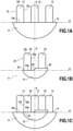
- FIG. 1a It has been illustrated on the Figure 1a the projection of a light beam from a first light module according to the invention onto a screen placed in a plane HV, and in which the line H is a horizontal line and the line V a vertical line.
- This light beam comprises a first beam 11, called the lower beam, participating in the production of dipped beam type lighting and a second beam 12, called the upper beam, participating in the production of road type lighting.
- the first 11 and second 12 beams formed by the first light module are selectively activatable.
- the second beam 12 comprises three selectively activatable light segments 13, located on a single line.
- Each segment 13 has a rectangular shape delimited by lateral edges 13a, a lower edge 13b and an upper edge 13c.
- the segments 13 all have the same width, measured between the lateral edges 13a of a segment 13.
- the segments 13 are distant from each other.
- the distance separating two consecutive light segments 13, measured between the neighboring lateral edges 13a of these segments, is equal to the width of a light segment 13.
- the lateral edges 13a of the light segments are sharp while each lower edge 13b is blurred.
- Each light segment has a light distribution such that the light intensity of the segment is maximum at the lower edge 13b and decreases as one moves away from the lower edge 13b towards the upper edge 13c.
- the first beam 11 forms only a portion of a regulatory dipped beam type lighting. In other words, the first beam 11 is not, by itself, regulatory.
- the first beam 11 has an upper cut-off 14 that is substantially flat over the entire width of the first beam 11 and parallel to the line H.
- the segments 13 of the second beam 12 are juxtaposed with the cut-off 14 of the first beam 11, that is to say that the lower edges 13b of these segments 13 are aligned with the cut-off 14 of the first beam 11. It could be envisaged without departing from the scope of the invention that the segments 13 partially overlap with the first beam 11, so that the lower edges 13b are arranged below the cut-off 14. Finally, a central light segment 13 is arranged so as to be centered on the vertical line V and the other light segments 13 are distributed on either side of this central light segment 13.
- This light beam comprises a first beam 21, called the lower beam, participating in the production of dipped beam type lighting and a second beam 22, called the upper beam, participating in the production of road type lighting.
- the first 21 and second 22 beams formed by the second light module are selectively activatable.
- the second beam comprises two selectively activatable light segments 23.
- Each of the light segments 23 is substantially identical, in particular in its shape, its dimensions and its light distribution, to the light segments 13 shown in figure 1a .
- each segment 23 has a rectangular shape delimited by lateral edges 23a, a lower edge 23b and an upper edge 23c and the segments 23 all have the same width, measured between the lateral edges 23a of the same segment 13, identical to that of the segments 13 of the figure 1a .
- the distance separating two consecutive light segments 23, measured between the neighboring lateral edges 23a of these segments is equal to the width of a light segment 23 and therefore of a light segment 13 of the figure 1a .
- the first beam 21 forms only a portion of a regulatory dipped beam type lighting. In other words, the first beam 21 is not, by itself, regulatory.
- the first beam 21 has an upper cut-off over the entire width of the beam with a substantially flat lower portion 24 parallel to the line H, a substantially flat upper portion 26 which is parallel to the lower portion 24 and an oblique portion 25 connecting the flat portions 24 and 26.
- the oblique portion 25 in particular makes an angle of 45° with the lower portion 24, it being understood that a person skilled in the art could envisage other angles without departing from the scope of the invention.
- the segments 23 of the second beam 22 are juxtaposed at the cut of the first beam 21, that is to say that the lower edges 23b of these segments 23 are aligned with the cut-off of the first beam 21. It could be envisaged, without departing from the scope of the invention, that the segments 23 partly overlap with the first beam 21, so that the lower edges 23b are arranged below the cut-off 14. Finally, the light segments 23 are distributed on either side of the vertical line V.
- FIG 1c schematically represents the projection of the light beam emitted by the first module, as shown in the Figure 1a , with the light beam emitted by the second module, as shown in the figure 1b , on the same screen placed in the HV plane of the Figures 1a and 1b .
- the light segments 13 of the first beam are interlaced with the light segments 23 by being juxtaposed with these light segments 23, so that each of the light segments 23 is arranged between two consecutive light segments 13 and that only the lateral edges 23a of this light segment 23 are in contact with one of the lateral edges 13a of the consecutive segments 13. In other words, no overlap is observed other than at the lateral edges between a segment 23 and a consecutive segment 13.
- the light segments 13, 23 are interlaced according to an alternation of a first segment 13 formed by the first light module and a second segment 23 formed by the second light module.
- the arrangement of the beams is such that the substantially flat upper cut-off 14 of the first beam 11 is aligned with the substantially flat lower portion 24 of the upper cut-off of the first beam 21.
- all of the light segments 13 and 23 of the second beams 12 and 22 thus form selective road lighting, each light segment of which can be selectively switched off when it is likely to dazzle a road user, whose presence is detected by a detection system.
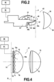
- FIG 2 is a side view of a light module 42 according to the invention making it possible to produce the beam shown in the Figure 1a .
- the light module 42 comprises a first light-emitting source 30 and three second light-emitting sources 34 arranged on the same heat sink 43.
- Each of the first 30 and second light-emitting sources of the light module comprises a chip of a light-emitting diode.
- This light module 42 comprises a single projection means 36 associated with the first 30 and second light emitting sources of this light module to project the beams from these light emitting sources 30, 34 outside the light module.
- the projection means 36 comprises a lens 35 having a focal zone 37, and in particular a focal plane P, supporting the focal zone 37.
- the first light-emitting source 30 is associated with a concave reflector portion 31 of the ellipsoidal type having a first focus f and a focal point F.
- the first light-emitting source 30 of the light module is arranged at the first focus f so that a majority of the light rays emitted by this first light-emitting source 30 are reflected by the reflector portion 31 in the vicinity of the focal point F, the focal point being located at the focal zone 37 of the projection means 36. These light rays are then projected by the projection means 36 to form the first beam 11 of the module.
- the light module 42 also comprises a cut-off member 39, an edge 40 of which is arranged at the focal zone 37 of the projection means of this light module.
- This cut-off member 39 is arranged so as to intercept a portion of the light rays emitted by the first light-emitting source 30 of this light module to form a cut-off 14 in the first beam 11 formed by this light module.
- the cut-off member further comprises a reflective surface 41 called a folding surface, extending on an upper face of the cut-off member, from the edge 40 towards the reflector portion 31.
- the portion of the light beam emitted by the first light-emitting source 30 which is intercepted by the cut-off member 39 therefore encounters this reflective surface 41 and is reflected in accordance with its angle of incidence on the surface towards the means of projection 36 to be projected below the cut-off line 14 of the first beam 11.
- Another part of the light beam emitted by the first light emitting source 30, which is not intercepted by the cut-off member, therefore passes beyond the edge of the reflecting surface 40, called the cut-off edge towards the projection means 36 to be projected below the cut-off line 14 of the first beam 11. It is understood that the shape of the cut-off edge 40 thus defines the shape of the cut-off 14 formed in the first beam 11.
- This cut-off edge 40 comprises a substantially flat portion over a substantial part of its width intended to intercept the light beam emitted by the source in order to form the upper cut-off 14 substantially flat over the entire length of the first beam 11.
- the rectangular output faces 34c of the light guides 32 are juxtaposed with the cut-off edge 40 of the cut-off member 39, such that an upper edge of each output face 34c of the light guides 32 is contiguous with the cut-off edge 40.
- the image of the first 30 and second 34 light sources are juxtaposed at the focal zone 37, which allows the cut-off 14 of the first beam 11 to be juxtaposed with the lower edges 13b of the light segments 13 of the second beam 12, when they are activated simultaneously.
- the light module 42 comprises a detection unit 44 arranged to detect a characteristic relating to the traffic conditions and/or the environment of the vehicle and/or the behavior of road users, and in particular to detect the presence of a vehicle encountered or followed on the road and likely to be dazzled by one of the light beams emitted by the lighting system.
- the light module 42 also comprises a control unit 45 arranged to selectively activate and/or deactivate one or more of the first 30 and second light emitting sources 34, in particular as a function of said detection by the detection unit so as to be able to selectively activate the three selectively activatable light segments 13. It is thus understood that each light segment 13 can be selectively extinguished when it is likely to dazzle a road user, whose presence is detected by the detection unit. The light module is therefore able to provide part of a selective road type lighting.
- FIG. 3a illustrates the projection of a light beam from a first light module which falls outside the scope of the invention onto a screen placed in a plane HV, and in which the line H is a horizontal line and the line V is a vertical line.
- This light beam comprises a first beam 50, called the lower beam, participating in the production of dipped beam type lighting and a second beam 51, called the upper beam, participating in the production of road type lighting.
- the first 50 and second 51 beams formed by the first light module are selectively activatable.
- the first beam 50 forms regulatory crossing type lighting on its own and the second beam 51 forms complementary road type lighting on its own.
- the first beam 50 comprises an upper cut-off 52, 53, 54 over the entire width of the beam with a substantially flat lower portion 52 parallel to the line H, a substantially flat upper portion 54 which is parallel to the lower portion 52 and an oblique portion 53 connecting the flat portions 52 and 54.
- the oblique portion 53 in particular makes an angle of 45° with the lower portion 52, it being understood that those skilled in the art could envisage other angles without departing from the scope of the invention.
- the second beam 51 is juxtaposed with the cut-off of the first beam 50, that is to say that a lower edge 51a of the second beam 51 is aligned with the cut-off of the first beam 52, 53, 54. It could be envisaged, outside the framework of the invention that the second beam 51 partly overlaps with the first beam 50 so that the lower edge 51a of the second beam 51 is arranged below the cut.
- FIG 3b illustrates the projection of a light beam from a second light module according to the invention onto a screen placed in the HV plane, as in Figure 3a
- This light beam comprises a first beam 60, called the lower beam, and a second beam 61, called the upper beam.
- the first beam 60 is exclusively formed by eighteen selectively activatable light segments 62 and the second beam 61 is exclusively formed by eighteen selectively activatable light segments 63.
- Each light segment 62 of the lower beam 60 has a substantially rectangular shape delimited by lateral edges 62a, a lower edge 62b and an upper edge 62c, it being understood that these segments could have other shapes, in particular trapezoids, diamonds, etc. without departing from the scope of the invention.
- the segments all have the same width, measured between the lateral edges 62a of a segment 62.
- the segments 62 are located on three lines parallel to the line H.
- Each line comprises six light segments 62 that can be selectively activated. These six selectively activatable light segments 62 are juxtaposed, that is to say that the lateral edge 62a of a first light segment 62 is aligned with the lateral edge 62a of another light segment 62.
- the lines are superimposed on each other, that is to say that the upper edges 62c of the light segments 62 located on a line are aligned with the lower edges 62b of the light segments 62 located on a lower neighboring line.
- the upper edges 62c of the light segments 62 located on the upper line of the first beam 60 form a substantially flat cut-off 64 over the entire width of the first beam 60.
- the light segments 63 of the second beam 61 have a shape and arrangement identical to the light segments 62 of the first beam 60.
- the first 60 and second 61 beams are juxtaposed, that is to say that the cut 64 of the first beam is aligned with the lower edges 63b of the light segments 63 located on the lower line of the second beam 61. It is therefore understood that all of the light segments 62 and 63 of the first and second light beams 60 and 61 form a matrix of segments, each segment of which can be selectively activated.
- FIG 3c schematically represents an example which goes beyond the scope of the invention; the projection of the light beam emitted by the first module, as shown in the Figure 3a , with the light beam emitted by the second module, as shown in the figure 3b , on the same screen placed in the HV plane of the Figure 3a and 3b .
- the arrangement of the beams is such that the substantially flat lower part 52 of the cut-off of the first beam 50 is aligned with the substantially flat upper cut-off 64 of the first beam 60. It could be envisaged, outside the scope of the invention, that the upper edge 65 of the second beam 61, formed by the upper edges 63c of the light segments 63 located on the upper line of the second beam 61, is aligned with the substantially flat upper part 54 of the cut-off of the first beam 50. It is thus understood that the first beam 60 is associated with the first beam 50 so as to be able to provide both regulatory dipped beam type lighting and a dynamic lighting function for bends, as will be seen later.
- FIG 4 is a side view of a light module 77 according to the invention making it possible to produce the beam shown in the figure 3b .
- This light module 77 comprises eighteen first light-emitting sources 70 and eighteen second light-emitting sources 71 arranged in a matrix of light-emitting sources of dimensions 6x6 arranged on the same support 78.
- Each of the first 70 and second 71 light-emitting sources of the light module comprises a chip of a light-emitting diode.
- This light module 77 comprises a single projection means 73 associated with the first 70 and second 71 light-emitting sources of this light module to project the beams from these light-emitting sources to the exterior of the light module.
- the projection means 73 comprises a lens 75 with a focal zone 74, and in particular a focal plane P.
- Each of the first 70 and second 71 light emitting sources is associated with a primary optical element 76, in the form of a microlens 76.
- Each microlens 76 is arranged to cooperate with the light emitting source 70, 71 associated therewith so as to form an image of this light emitting source at the focal zone 74 of the projection means 73 of the light module 77, this image being intended to be projected by the projection means 73 to form one of said light segments 62, 63.
- the focal zone 74 of the projection means 73 is arranged behind the light emitting sources 70 and 71, and each microlens 76 is arranged to form a virtual image of the associated light emitting source at this focal zone 74.
- the microlenses are arranged in the form of a microlens matrix 72, of dimensions identical to those of the matrix of light-emitting sources.
- This microlens matrix 72 has a light entry surface 72a, segmented into as many light entry facets as there are light-emitting sources, and a light exit surface 72b, of substantially spherical shape, intended to correct optical aberrations generated by the projection means 74.
- the light module 77 comprises a detection unit 80 arranged to detect a characteristic relating to the traffic conditions and/or the environment of the vehicle and/or the behavior of road users, in particular to detect the presence of a bend upstream of the road taken by the vehicle.
- the light module 77 also comprises a control unit 81 arranged to selectively activate and/or deactivate one or more of the first 70 and/or second 71 light emitting sources as a function of said detection by the detection unit so as to be able to selectively activate one or more of the thirty-six selectively activatable light segments 62, 63, so as to progressively illuminate the bend taken by the vehicle.
- the light module thus performs a dynamic bend lighting function.
- the person skilled in the art will be able to easily adapt the module presented on the figure 2 , for example by using only a second light emitting source, by replacing the optical guides with a reflector portion substantially identical to the reflector portion associated with the first source and by arranging this reflector portion to reflect the light beam emitted by the second source at the cut-off edge of the cut-off member of the module, a portion of this light beam therefore being intercepted by the cut-off member and another portion being reflected towards the projection means to be projected above the cut-off line formed by the cut-off edge of the cut-off member.
Landscapes
- Engineering & Computer Science (AREA)
- General Engineering & Computer Science (AREA)
- Microelectronics & Electronic Packaging (AREA)
- Physics & Mathematics (AREA)
- Optics & Photonics (AREA)
- Non-Portable Lighting Devices Or Systems Thereof (AREA)
Claims (9)
- Leuchtsystem für eine Beleuchtungsvorrichtung und, optional, Signalisierungsvorrichtung eines Kraftfahrzeugs, umfassend erste (42) und zweite (77) Leuchtmodule;wobei mindestens das erste Leuchtmodul (42) dazu eingerichtet ist, dass das von diesem ersten Leuchtmodul gebildete erste Bündel einen Abschnitt nur einer vorschriftsmäßigen Beleuchtung vom Typ Abblendlicht bildet, wobei die Leuchtmodule dazu eingerichtet sind, dass die ersten Bündel, wenn sie zusammen aktiviert sind, die Gesamtheit einer vorschriftsmäßigen Beleuchtung vom Typ Abblendlicht bilden, und wobei jedes Leuchtmodul (42; 77) dazu eingerichtet ist, ein erstes Bündel (11, 21, 60), unteres Bündel genannt, das zur Realisierung einer Beleuchtung vom Typ Abblendlicht beiträgt, und ein zweites Bündel (12, 22, 61), oberes Bündel genannt, das zur Realisierung einer Beleuchtung vom Typ Fernlicht beiträgt, zu bilden:wobei die ersten und zweiten Bündel, die von jedem Leuchtmodul gebildet werden, selektiv aktivierbar sind;wobei mindestens eines der Leuchtmodule Lichtemissionsmittel (34, 32; 70, 71, 76) umfasst, die dazu eingerichtet sind, mindestens zwei selektiv aktivierbare Leuchtsegmente (13, 23; 62, 63) in einem der ersten und zweiten Bündel, die von diesem Leuchtmodul gebildet werden, zu bilden;wobei jedes Leuchtmodul (42; 77) umfasst:- mindestens erste (30; 70) und zweite (34; 71) Licht emittierende Quellen;- mindestens ein optisches System (36; 73), das durch ein einziges Projektionsmittel gebildet wird, das diesen ersten und zweiten Licht emittierenden Quellen zugeordnet ist, um die aus diesen Licht emittierenden Quellen hervorgegangenen Bündel nach außerhalb des Leuchtmoduls zu projizieren;wobei die ersten und zweiten Licht emittierenden Quellen jedes Leuchtmoduls dazu eingerichtet sind, mit dem zugeordneten optischen System zusammenzuwirken, um die ersten (11, 21, 60) beziehungsweise zweiten (12, 22, 61) Bündel, die von diesem Leuchtmodul gebildet werden, zu bilden,wobei die ersten und zweiten Leuchtmodule in einem selben Scheinwerfer des Kraftfahrzeugs eingerichtet sind, und dadurch gekennzeichnet, dass jedes der beiden Leuchtmodule (42, 77) Lichtemissionsmittel (34, 32; 71, 76) umfasst, die dazu eingerichtet sind, mindestens zwei selektiv aktivierbare Leuchtsegmente (13, 23; 63) in jedem der beiden Bündel (12, 22; 61), die von diesen Leuchtmodulen gebildet werden, zu bilden, wobei die mindestens zwei selektiv aktivierbaren Leuchtsegmente so angeordnet sind, dass zwischen zwei aufeinander folgenden Segmenten ein Raum besteht, der von den aufeinander folgenden Segmenten nicht beleuchtet wird, unddadurch, dass die Lichtemissionsmittel (34, 32) jedes der Leuchtmodule (42) so eingerichtet sind, dass die Leuchtsegmente (13), die von den Emissionsmitteln des ersten Leuchtmoduls gebildet werden, in die Leuchtsegmente (23), die von den Emissionsmitteln des zweiten Leuchtmoduls gebildet werden, verschachtelt sind, wenn sie gleichzeitig aktiviert sind, so dass mindestens ein Leuchtsegment, dass von den Emissionsmitteln des ersten Leuchtmoduls gebildet wird, erstes Leuchtsegment genannt, zwischen zwei Leuchtsegmenten, die von den Emissionsmitteln des zweiten Leuchtmoduls gebildet werden, zweite Segmente genannt, angeordnet ist.
- Leuchtsystem nach Anspruch 1, dadurch gekennzeichnet, dass mindestens eines der Leuchtmodule (77) Lichtemissionsmittel (70, 76), die dazu eingerichtet sind, mindestens zwei selektiv aktivierbare Leuchtsegmente (62) in dem ersten Bündel (60), das von diesem Leuchtmodul gebildet wird, zu bilden, und Lichtemissionsmittel (71, 76), die dazu eingerichtet sind, mindestens zwei selektiv aktivierbare Leuchtsegmente (63) in dem zweiten Leuchtmodul (61), das von diesem Leuchtmodul gebildet wird, zu bilden, umfasst.
- Leuchtsystem nach einem der vorhergehenden Ansprüche, dadurch gekennzeichnet, dass die Lichtemissionsmittel (34, 32) des Leuchtmoduls (42) so eingerichtet sind, dass die selektiv aktivierbaren Leuchtsegmente (13, 23) auf einer einzigen Linie gelegen sind.
- Leuchtsystem nach einem der Ansprüche 1 bis 2, dadurch gekennzeichnet, dass die Lichtemissionsmittel (70, 71, 76) des Leuchtmoduls so eingerichtet sind, dass die selektiv aktivierbaren Leuchtsegmente (62, 63) auf mehreren Linien gelegen sind.
- Leuchtsystem nach einem der vorhergehenden Ansprüche, dadurch gekennzeichnet, dass das zweite Leuchtmodul (42) dazu eingerichtet ist, dass das erste Bündel (11, 21), das von diesem zweiten Leuchtmodul gebildet wird, einen Abschnitt nur einer vorschriftsmäßigen Beleuchtung vom Typ Abblendlicht bildet, und dadurch, dass die Leuchtmodule dazu eingerichtet sind, dass die ersten Bündel, wenn sie zusammen aktiviert sind, eine vorschriftsmäßige Beleuchtung vom Typ Abblendlicht bilden.
- Leuchtsystem nach einem der vorhergehenden Ansprüche, dadurch gekennzeichnet, dass das Leuchtmodul (42, 77), das die Lichtemissionsmittel (34, 32; 70, 71, 76) umfasst, die dazu eingerichtet sind, mindestens zwei selektiv aktivierbare Leuchtsegmente (13, 23; 62, 63) zu bilden, mindestens zwei Licht emittierende Halbleiterquellen (34; 70, 71) umfasst, wobei die Emissionsmittel die mindestens zwei Licht emittierenden Halbleiterquellen umfassen.
- Leuchtsystem nach einem der vorhergehenden Ansprüche, dadurch gekennzeichnet, dass das zweite Leuchtmodul ein Trennorgan umfasst, das dazu eingerichtet ist, einen Teil der von der ersten Licht emittierenden Quelle dieses zweiten Leuchtmoduls emittierten Lichtstrahlen zurückzuhalten, um eine Hell-Dunkel-Grenze (24, 25, 26) in dem ersten Bündel (21), das von diesem zweiten Leuchtmodul gebildet wird, zu bilden.
- Leuchtsystem nach einem der vorhergehenden Ansprüche, dadurch gekennzeichnet, dass das erste Leuchtmodul (42) ein Trennorgan (39) umfasst, das dazu eingerichtet ist, einen Teil der von der ersten Licht emittierenden Quelle (30) dieses ersten Leuchtmoduls emittierten Lichtstrahlen zurückzuhalten, um eine Hell-Dunkel-Grenze (14) in dem ersten Bündel (11), das von diesem ersten Leuchtmodul gebildet wird, zu bilden.
- Leuchtsystem nach einem der vorhergehenden Ansprüche, dadurch gekennzeichnet, dass das erste Leuchtmodul (77) die Emissionsmittel (70, 71, 76) umfasst, wobei die Emissionsmittel eine Matrix aus Licht emittierenden Quellen (70, 71) umfassen, um mindestens zwei selektiv aktivierbare Leuchtsegmente (62, 63) in jedem der ersten (60) und zweiten (61) Bündel, die von diesem ersten Leuchtmodul gebildet werden, zu bilden.
Applications Claiming Priority (1)
| Application Number | Priority Date | Filing Date | Title |
|---|---|---|---|
| FR1657096A FR3054295B1 (fr) | 2016-07-25 | 2016-07-25 | Systeme lumineux pour dispositif d'eclairage et/ou de signalisation d'un vehicule automobile |
Publications (2)
| Publication Number | Publication Date |
|---|---|
| EP3276249A1 EP3276249A1 (de) | 2018-01-31 |
| EP3276249B1 true EP3276249B1 (de) | 2025-03-05 |
Family
ID=57121351
Family Applications (1)
| Application Number | Title | Priority Date | Filing Date |
|---|---|---|---|
| EP17181259.7A Active EP3276249B1 (de) | 2016-07-25 | 2017-07-13 | Leuchtsystem für beleuchtungsvorrichtung und optional für signalvorrichtung für kraftfahrzeug |
Country Status (3)
| Country | Link |
|---|---|
| EP (1) | EP3276249B1 (de) |
| CN (1) | CN107654955B (de) |
| FR (1) | FR3054295B1 (de) |
Family Cites Families (19)
| Publication number | Priority date | Publication date | Assignee | Title |
|---|---|---|---|---|
| DE102005041234A1 (de) * | 2005-08-31 | 2007-03-01 | Hella Kgaa Hueck & Co. | Scheinwerfer für Fahrzeuge |
| FR2893701B1 (fr) * | 2005-11-24 | 2010-03-26 | Valeo Vision | Dispositif d'eclairage et/ou de signalisation pour automobile |
| JP4663548B2 (ja) * | 2006-02-24 | 2011-04-06 | 株式会社小糸製作所 | 車両用前照灯の灯具ユニット |
| TW201002552A (en) * | 2008-07-10 | 2010-01-16 | Tyc Brother Ind Co Ltd | Semiconductor solid-state illumination automobile head light with high/low beam switching function |
| DE102008036193B4 (de) * | 2008-08-02 | 2020-03-12 | Automotive Lighting Reutlingen Gmbh | Beleuchtungseinrichtung für ein Kraftfahrzeug |
| JP5577138B2 (ja) * | 2010-04-08 | 2014-08-20 | スタンレー電気株式会社 | 車両用前照灯 |
| FR2965326B1 (fr) * | 2010-09-29 | 2015-09-25 | Valeo Vision | Dispositif d'emission de lumiere pour projecteur d'un vehicule automobile |
| JP5666882B2 (ja) * | 2010-11-18 | 2015-02-12 | 株式会社小糸製作所 | ハイビーム用灯具ユニット |
| DE102011013211B4 (de) * | 2011-03-05 | 2012-12-06 | Automotive Lighting Reutlingen Gmbh | Kraftfahrzeugscheinwerfer mit einem Mehrfunktions-Projektionsmodul |
| JP5719697B2 (ja) * | 2011-06-10 | 2015-05-20 | 株式会社小糸製作所 | 車両の前照灯装置 |
| JP5823211B2 (ja) * | 2011-09-01 | 2015-11-25 | 株式会社小糸製作所 | 車両用前照灯装置 |
| AT512246B1 (de) * | 2011-11-22 | 2014-02-15 | Zizala Lichtsysteme Gmbh | Led-projektionsmodul und scheinwerfer mit modul |
| JP5938204B2 (ja) * | 2011-12-21 | 2016-06-22 | 株式会社小糸製作所 | 車両用前照灯装置 |
| JP2013242996A (ja) * | 2012-05-18 | 2013-12-05 | Koito Mfg Co Ltd | 車両用前照灯 |
| FR3006421B1 (fr) * | 2013-05-30 | 2017-08-11 | Valeo Vision | Module d'eclairage pour projecteur de vehicule automobile, projecteur equipe de tels modules, et ensemble de projecteurs |
| JP6226669B2 (ja) * | 2013-09-25 | 2017-11-08 | ライト プレスクリプションズ イノベーターズ エルエルシー | 車両用灯具 |
| DE102014102871B4 (de) * | 2014-03-05 | 2023-06-22 | HELLA GmbH & Co. KGaA | Beleuchtungsvorrichtung für Fahrzeuge |
| FR3026461B1 (fr) * | 2014-09-30 | 2019-04-05 | Valeo Vision | Module lumineux pour l'eclairage et/ou la signalisation d'un vehicule automobile |
| DE102014226650B4 (de) * | 2014-12-19 | 2023-05-25 | Osram Gmbh | Leuchte |
-
2016
- 2016-07-25 FR FR1657096A patent/FR3054295B1/fr active Active
-
2017
- 2017-07-13 EP EP17181259.7A patent/EP3276249B1/de active Active
- 2017-07-24 CN CN201710605717.2A patent/CN107654955B/zh active Active
Also Published As
| Publication number | Publication date |
|---|---|
| FR3054295A1 (fr) | 2018-01-26 |
| FR3054295B1 (fr) | 2022-08-26 |
| CN107654955A (zh) | 2018-02-02 |
| EP3276249A1 (de) | 2018-01-31 |
| CN107654955B (zh) | 2024-04-23 |
Similar Documents
| Publication | Publication Date | Title |
|---|---|---|
| EP3147557B1 (de) | Primäres optisches element für kraftfahrzeugsbeleuchtungsmodul | |
| EP2871406B1 (de) | Optisches Hauptelement, Beleuchtungsmodul und Scheinwerfer für Kraftfahrzeug | |
| EP3301348B1 (de) | Bandförmige beleuchtungsvorrichtung für kraftfahrzeugscheinwerfer | |
| EP3167226B1 (de) | Beleuchtungsmodul für ein kraftfahrzeug | |
| EP3002504B1 (de) | Leuchtmodul zur beleuchtung für kraftfahrzeug | |
| EP2743567B1 (de) | Optisches hauptelement, beleuchtungsmodul und scheinwerfer für kraftfahrzeug | |
| EP3636990B1 (de) | Beleuchtungsvorrichtung für kraftfahrzeug, die einen lichtwellenleiter umfasst | |
| WO2020025171A1 (fr) | Module lumineux imageant la surface eclairee d'un collecteur | |
| EP3708904A1 (de) | Leuchtvorrichtung, die die beleuchteten flächen von mindestens zwei kollektoren abbildet | |
| EP3093557B1 (de) | Beleuchtungsmodul mit doppelfunktion für abblend- und fernlicht für kraftfahrzeug | |
| FR2934669A1 (fr) | Installation d'eclairage de vehicule automobile | |
| FR2995967B1 (fr) | Module d'eclairage, notamment pour vehicule automobile | |
| EP3511608B1 (de) | Optisches modul für ein kraftfahrzeug | |
| FR3093788A1 (fr) | Dispositif lumineux imageant une surface eclairee virtuelle d’un collecteur | |
| FR3038695A1 (fr) | Module lumineux pour l'eclairage et/ou la signalisation d'un vehicule automobile | |
| EP4285051B1 (de) | Kraftfahrzeugvorrichtung zur beleuchtung der strasse | |
| EP2416061A2 (de) | Beleuchtungsmodul mit Abschaltfunktion mit einem Parabolreflektor, der auf einem elliptischen Reflektor angebracht ist | |
| EP3124853B1 (de) | Vorrichtung zur beleuchtung und/oder signalisierung für kraftfahrzeug | |
| EP3276249B1 (de) | Leuchtsystem für beleuchtungsvorrichtung und optional für signalvorrichtung für kraftfahrzeug | |
| FR3041072A1 (fr) | Module d'eclairage de projecteur de vehicule automobile et projecteur associe | |
| FR3056695A1 (fr) | Dispositif d'eclairage pour vehicule automobile comportant un guide de lumiere | |
| WO2021099290A1 (fr) | Module d'eclairage pour vehicule a coupure modulable entre conduite a gauche et conduite a droite | |
| FR3146191A1 (fr) | Module lumineux d’un véhicule automobile | |
| WO2023030808A1 (fr) | Module lumineux pour vehicule automobile |
Legal Events
| Date | Code | Title | Description |
|---|---|---|---|
| PUAI | Public reference made under article 153(3) epc to a published international application that has entered the european phase |
Free format text: ORIGINAL CODE: 0009012 |
|
| STAA | Information on the status of an ep patent application or granted ep patent |
Free format text: STATUS: THE APPLICATION HAS BEEN PUBLISHED |
|
| AK | Designated contracting states |
Kind code of ref document: A1 Designated state(s): AL AT BE BG CH CY CZ DE DK EE ES FI FR GB GR HR HU IE IS IT LI LT LU LV MC MK MT NL NO PL PT RO RS SE SI SK SM TR |
|
| AX | Request for extension of the european patent |
Extension state: BA ME |
|
| STAA | Information on the status of an ep patent application or granted ep patent |
Free format text: STATUS: REQUEST FOR EXAMINATION WAS MADE |
|
| 17P | Request for examination filed |
Effective date: 20180627 |
|
| RBV | Designated contracting states (corrected) |
Designated state(s): AL AT BE BG CH CY CZ DE DK EE ES FI FR GB GR HR HU IE IS IT LI LT LU LV MC MK MT NL NO PL PT RO RS SE SI SK SM TR |
|
| STAA | Information on the status of an ep patent application or granted ep patent |
Free format text: STATUS: EXAMINATION IS IN PROGRESS |
|
| 17Q | First examination report despatched |
Effective date: 20211008 |
|
| P01 | Opt-out of the competence of the unified patent court (upc) registered |
Effective date: 20230528 |
|
| REG | Reference to a national code |
Ref country code: DE Ref legal event code: R079 Ipc: F21S0041143000 Ref country code: DE Ref legal event code: R079 Ref document number: 602017088132 Country of ref document: DE Free format text: PREVIOUS MAIN CLASS: F21S0008000000 Ipc: F21S0041143000 |
|
| RIC1 | Information provided on ipc code assigned before grant |
Ipc: F21S 45/47 20180101ALI20240228BHEP Ipc: F21S 41/663 20180101ALI20240228BHEP Ipc: F21S 41/40 20180101ALI20240228BHEP Ipc: F21S 41/255 20180101ALI20240228BHEP Ipc: F21S 41/24 20180101ALI20240228BHEP Ipc: F21S 41/147 20180101ALI20240228BHEP Ipc: F21S 41/143 20180101AFI20240228BHEP |
|
| GRAP | Despatch of communication of intention to grant a patent |
Free format text: ORIGINAL CODE: EPIDOSNIGR1 |
|
| STAA | Information on the status of an ep patent application or granted ep patent |
Free format text: STATUS: GRANT OF PATENT IS INTENDED |
|
| INTG | Intention to grant announced |
Effective date: 20240513 |
|
| GRAJ | Information related to disapproval of communication of intention to grant by the applicant or resumption of examination proceedings by the epo deleted |
Free format text: ORIGINAL CODE: EPIDOSDIGR1 |
|
| STAA | Information on the status of an ep patent application or granted ep patent |
Free format text: STATUS: EXAMINATION IS IN PROGRESS |
|
| GRAP | Despatch of communication of intention to grant a patent |
Free format text: ORIGINAL CODE: EPIDOSNIGR1 |
|
| STAA | Information on the status of an ep patent application or granted ep patent |
Free format text: STATUS: GRANT OF PATENT IS INTENDED |
|
| INTC | Intention to grant announced (deleted) | ||
| INTG | Intention to grant announced |
Effective date: 20240926 |
|
| GRAS | Grant fee paid |
Free format text: ORIGINAL CODE: EPIDOSNIGR3 |
|
| GRAA | (expected) grant |
Free format text: ORIGINAL CODE: 0009210 |
|
| STAA | Information on the status of an ep patent application or granted ep patent |
Free format text: STATUS: THE PATENT HAS BEEN GRANTED |
|
| AK | Designated contracting states |
Kind code of ref document: B1 Designated state(s): AL AT BE BG CH CY CZ DE DK EE ES FI FR GB GR HR HU IE IS IT LI LT LU LV MC MK MT NL NO PL PT RO RS SE SI SK SM TR |
|
| REG | Reference to a national code |
Ref country code: GB Ref legal event code: FG4D Free format text: NOT ENGLISH |
|
| REG | Reference to a national code |
Ref country code: CH Ref legal event code: EP |
|
| REG | Reference to a national code |
Ref country code: IE Ref legal event code: FG4D Free format text: LANGUAGE OF EP DOCUMENT: FRENCH |
|
| REG | Reference to a national code |
Ref country code: DE Ref legal event code: R096 Ref document number: 602017088132 Country of ref document: DE |
|
| PG25 | Lapsed in a contracting state [announced via postgrant information from national office to epo] |
Ref country code: RS Free format text: LAPSE BECAUSE OF FAILURE TO SUBMIT A TRANSLATION OF THE DESCRIPTION OR TO PAY THE FEE WITHIN THE PRESCRIBED TIME-LIMIT Effective date: 20250605 |
|
| PG25 | Lapsed in a contracting state [announced via postgrant information from national office to epo] |
Ref country code: FI Free format text: LAPSE BECAUSE OF FAILURE TO SUBMIT A TRANSLATION OF THE DESCRIPTION OR TO PAY THE FEE WITHIN THE PRESCRIBED TIME-LIMIT Effective date: 20250305 |
|
| REG | Reference to a national code |
Ref country code: NL Ref legal event code: MP Effective date: 20250305 |
|
| PG25 | Lapsed in a contracting state [announced via postgrant information from national office to epo] |
Ref country code: ES Free format text: LAPSE BECAUSE OF FAILURE TO SUBMIT A TRANSLATION OF THE DESCRIPTION OR TO PAY THE FEE WITHIN THE PRESCRIBED TIME-LIMIT Effective date: 20250305 |
|
| REG | Reference to a national code |
Ref country code: LT Ref legal event code: MG9D |
|
| PG25 | Lapsed in a contracting state [announced via postgrant information from national office to epo] |
Ref country code: NO Free format text: LAPSE BECAUSE OF FAILURE TO SUBMIT A TRANSLATION OF THE DESCRIPTION OR TO PAY THE FEE WITHIN THE PRESCRIBED TIME-LIMIT Effective date: 20250605 |
|
| PG25 | Lapsed in a contracting state [announced via postgrant information from national office to epo] |
Ref country code: HR Free format text: LAPSE BECAUSE OF FAILURE TO SUBMIT A TRANSLATION OF THE DESCRIPTION OR TO PAY THE FEE WITHIN THE PRESCRIBED TIME-LIMIT Effective date: 20250305 |
|
| PG25 | Lapsed in a contracting state [announced via postgrant information from national office to epo] |
Ref country code: LV Free format text: LAPSE BECAUSE OF FAILURE TO SUBMIT A TRANSLATION OF THE DESCRIPTION OR TO PAY THE FEE WITHIN THE PRESCRIBED TIME-LIMIT Effective date: 20250305 |
|
| PG25 | Lapsed in a contracting state [announced via postgrant information from national office to epo] |
Ref country code: GR Free format text: LAPSE BECAUSE OF FAILURE TO SUBMIT A TRANSLATION OF THE DESCRIPTION OR TO PAY THE FEE WITHIN THE PRESCRIBED TIME-LIMIT Effective date: 20250606 Ref country code: BG Free format text: LAPSE BECAUSE OF FAILURE TO SUBMIT A TRANSLATION OF THE DESCRIPTION OR TO PAY THE FEE WITHIN THE PRESCRIBED TIME-LIMIT Effective date: 20250305 |
|
| REG | Reference to a national code |
Ref country code: AT Ref legal event code: MK05 Ref document number: 1773206 Country of ref document: AT Kind code of ref document: T Effective date: 20250305 |
|
| PG25 | Lapsed in a contracting state [announced via postgrant information from national office to epo] |
Ref country code: NL Free format text: LAPSE BECAUSE OF FAILURE TO SUBMIT A TRANSLATION OF THE DESCRIPTION OR TO PAY THE FEE WITHIN THE PRESCRIBED TIME-LIMIT Effective date: 20250305 |
|
| PG25 | Lapsed in a contracting state [announced via postgrant information from national office to epo] |
Ref country code: SE Free format text: LAPSE BECAUSE OF FAILURE TO SUBMIT A TRANSLATION OF THE DESCRIPTION OR TO PAY THE FEE WITHIN THE PRESCRIBED TIME-LIMIT Effective date: 20250305 |
|
| PG25 | Lapsed in a contracting state [announced via postgrant information from national office to epo] |
Ref country code: SM Free format text: LAPSE BECAUSE OF FAILURE TO SUBMIT A TRANSLATION OF THE DESCRIPTION OR TO PAY THE FEE WITHIN THE PRESCRIBED TIME-LIMIT Effective date: 20250305 |
|
| PG25 | Lapsed in a contracting state [announced via postgrant information from national office to epo] |
Ref country code: PT Free format text: LAPSE BECAUSE OF FAILURE TO SUBMIT A TRANSLATION OF THE DESCRIPTION OR TO PAY THE FEE WITHIN THE PRESCRIBED TIME-LIMIT Effective date: 20250707 |
|
| PGFP | Annual fee paid to national office [announced via postgrant information from national office to epo] |
Ref country code: DE Payment date: 20250711 Year of fee payment: 9 |
|
| PG25 | Lapsed in a contracting state [announced via postgrant information from national office to epo] |
Ref country code: PL Free format text: LAPSE BECAUSE OF FAILURE TO SUBMIT A TRANSLATION OF THE DESCRIPTION OR TO PAY THE FEE WITHIN THE PRESCRIBED TIME-LIMIT Effective date: 20250305 Ref country code: IT Free format text: LAPSE BECAUSE OF FAILURE TO SUBMIT A TRANSLATION OF THE DESCRIPTION OR TO PAY THE FEE WITHIN THE PRESCRIBED TIME-LIMIT Effective date: 20250305 |
|
| PG25 | Lapsed in a contracting state [announced via postgrant information from national office to epo] |
Ref country code: AT Free format text: LAPSE BECAUSE OF FAILURE TO SUBMIT A TRANSLATION OF THE DESCRIPTION OR TO PAY THE FEE WITHIN THE PRESCRIBED TIME-LIMIT Effective date: 20250305 |
|
| PGFP | Annual fee paid to national office [announced via postgrant information from national office to epo] |
Ref country code: FR Payment date: 20250730 Year of fee payment: 9 |
|
| PG25 | Lapsed in a contracting state [announced via postgrant information from national office to epo] |
Ref country code: EE Free format text: LAPSE BECAUSE OF FAILURE TO SUBMIT A TRANSLATION OF THE DESCRIPTION OR TO PAY THE FEE WITHIN THE PRESCRIBED TIME-LIMIT Effective date: 20250305 Ref country code: CZ Free format text: LAPSE BECAUSE OF FAILURE TO SUBMIT A TRANSLATION OF THE DESCRIPTION OR TO PAY THE FEE WITHIN THE PRESCRIBED TIME-LIMIT Effective date: 20250305 |
|
| PG25 | Lapsed in a contracting state [announced via postgrant information from national office to epo] |
Ref country code: RO Free format text: LAPSE BECAUSE OF FAILURE TO SUBMIT A TRANSLATION OF THE DESCRIPTION OR TO PAY THE FEE WITHIN THE PRESCRIBED TIME-LIMIT Effective date: 20250305 |
|
| PG25 | Lapsed in a contracting state [announced via postgrant information from national office to epo] |
Ref country code: SK Free format text: LAPSE BECAUSE OF FAILURE TO SUBMIT A TRANSLATION OF THE DESCRIPTION OR TO PAY THE FEE WITHIN THE PRESCRIBED TIME-LIMIT Effective date: 20250305 |
|
| PG25 | Lapsed in a contracting state [announced via postgrant information from national office to epo] |
Ref country code: IS Free format text: LAPSE BECAUSE OF FAILURE TO SUBMIT A TRANSLATION OF THE DESCRIPTION OR TO PAY THE FEE WITHIN THE PRESCRIBED TIME-LIMIT Effective date: 20250705 |