EP3276158B1 - Hydraulikturbine - Google Patents
Hydraulikturbine Download PDFInfo
- Publication number
- EP3276158B1 EP3276158B1 EP17182724.9A EP17182724A EP3276158B1 EP 3276158 B1 EP3276158 B1 EP 3276158B1 EP 17182724 A EP17182724 A EP 17182724A EP 3276158 B1 EP3276158 B1 EP 3276158B1
- Authority
- EP
- European Patent Office
- Prior art keywords
- runner
- clearance
- stator
- ratio
- crown
- Prior art date
- Legal status (The legal status is an assumption and is not a legal conclusion. Google has not performed a legal analysis and makes no representation as to the accuracy of the status listed.)
- Active
Links
Images


Classifications
-
- F—MECHANICAL ENGINEERING; LIGHTING; HEATING; WEAPONS; BLASTING
- F03—MACHINES OR ENGINES FOR LIQUIDS; WIND, SPRING, OR WEIGHT MOTORS; PRODUCING MECHANICAL POWER OR A REACTIVE PROPULSIVE THRUST, NOT OTHERWISE PROVIDED FOR
- F03B—MACHINES OR ENGINES FOR LIQUIDS
- F03B11/00—Parts or details not provided for in, or of interest apart from, the preceding groups, e.g. wear-protection couplings, between turbine and generator
- F03B11/04—Parts or details not provided for in, or of interest apart from, the preceding groups, e.g. wear-protection couplings, between turbine and generator for diminishing cavitation or vibration, e.g. balancing
-
- F—MECHANICAL ENGINEERING; LIGHTING; HEATING; WEAPONS; BLASTING
- F03—MACHINES OR ENGINES FOR LIQUIDS; WIND, SPRING, OR WEIGHT MOTORS; PRODUCING MECHANICAL POWER OR A REACTIVE PROPULSIVE THRUST, NOT OTHERWISE PROVIDED FOR
- F03B—MACHINES OR ENGINES FOR LIQUIDS
- F03B11/00—Parts or details not provided for in, or of interest apart from, the preceding groups, e.g. wear-protection couplings, between turbine and generator
- F03B11/006—Sealing arrangements
-
- F—MECHANICAL ENGINEERING; LIGHTING; HEATING; WEAPONS; BLASTING
- F03—MACHINES OR ENGINES FOR LIQUIDS; WIND, SPRING, OR WEIGHT MOTORS; PRODUCING MECHANICAL POWER OR A REACTIVE PROPULSIVE THRUST, NOT OTHERWISE PROVIDED FOR
- F03B—MACHINES OR ENGINES FOR LIQUIDS
- F03B3/00—Machines or engines of reaction type; Parts or details peculiar thereto
- F03B3/02—Machines or engines of reaction type; Parts or details peculiar thereto with radial flow at high-pressure side and axial flow at low-pressure side of rotors, e.g. Francis turbines
-
- F—MECHANICAL ENGINEERING; LIGHTING; HEATING; WEAPONS; BLASTING
- F03—MACHINES OR ENGINES FOR LIQUIDS; WIND, SPRING, OR WEIGHT MOTORS; PRODUCING MECHANICAL POWER OR A REACTIVE PROPULSIVE THRUST, NOT OTHERWISE PROVIDED FOR
- F03B—MACHINES OR ENGINES FOR LIQUIDS
- F03B3/00—Machines or engines of reaction type; Parts or details peculiar thereto
- F03B3/12—Blades; Blade-carrying rotors
- F03B3/125—Rotors for radial flow at high-pressure side and axial flow at low-pressure side, e.g. for Francis-type turbines
-
- F—MECHANICAL ENGINEERING; LIGHTING; HEATING; WEAPONS; BLASTING
- F03—MACHINES OR ENGINES FOR LIQUIDS; WIND, SPRING, OR WEIGHT MOTORS; PRODUCING MECHANICAL POWER OR A REACTIVE PROPULSIVE THRUST, NOT OTHERWISE PROVIDED FOR
- F03B—MACHINES OR ENGINES FOR LIQUIDS
- F03B3/00—Machines or engines of reaction type; Parts or details peculiar thereto
- F03B3/16—Stators
- F03B3/18—Stator blades; Guide conduits or vanes, e.g. adjustable
-
- F—MECHANICAL ENGINEERING; LIGHTING; HEATING; WEAPONS; BLASTING
- F05—INDEXING SCHEMES RELATING TO ENGINES OR PUMPS IN VARIOUS SUBCLASSES OF CLASSES F01-F04
- F05B—INDEXING SCHEME RELATING TO WIND, SPRING, WEIGHT, INERTIA OR LIKE MOTORS, TO MACHINES OR ENGINES FOR LIQUIDS COVERED BY SUBCLASSES F03B, F03D AND F03G
- F05B2260/00—Function
- F05B2260/96—Preventing, counteracting or reducing vibration or noise
-
- F—MECHANICAL ENGINEERING; LIGHTING; HEATING; WEAPONS; BLASTING
- F16—ENGINEERING ELEMENTS AND UNITS; GENERAL MEASURES FOR PRODUCING AND MAINTAINING EFFECTIVE FUNCTIONING OF MACHINES OR INSTALLATIONS; THERMAL INSULATION IN GENERAL
- F16J—PISTONS; CYLINDERS; SEALINGS
- F16J15/00—Sealings
- F16J15/16—Sealings between relatively-moving surfaces
- F16J15/164—Sealings between relatively-moving surfaces the sealing action depending on movements; pressure difference, temperature or presence of leaking fluid
-
- Y—GENERAL TAGGING OF NEW TECHNOLOGICAL DEVELOPMENTS; GENERAL TAGGING OF CROSS-SECTIONAL TECHNOLOGIES SPANNING OVER SEVERAL SECTIONS OF THE IPC; TECHNICAL SUBJECTS COVERED BY FORMER USPC CROSS-REFERENCE ART COLLECTIONS [XRACs] AND DIGESTS
- Y02—TECHNOLOGIES OR APPLICATIONS FOR MITIGATION OR ADAPTATION AGAINST CLIMATE CHANGE
- Y02E—REDUCTION OF GREENHOUSE GAS [GHG] EMISSIONS, RELATED TO ENERGY GENERATION, TRANSMISSION OR DISTRIBUTION
- Y02E10/00—Energy generation through renewable energy sources
- Y02E10/20—Hydro energy
Definitions
- the present invention relates to the technology of hydraulic machines. It refers to a hydraulic turbine according to the preamble of claim 1.
- Fig. 1 shows as an example the main parts of a hydraulic turbine of the Francis type.
- the hydraulic turbine 10 of Fig. 1 comprises a vertical rotor with a runner 12 and a turbine shaft 12a.
- Runner 12 comprises a plurality of runner blades 16 distributed in a ring around the rotor axis.
- Rotor 12, 12a is concentrically surrounded by a stator 11, which is arranged between rotor 12, 12a and a surrounding scroll casing 13.
- Stator 11 is equipped with a plurality of fixed and movable guide vanes 15.
- Guide vanes 15 direct the stream of water, which is supplied through scroll casing 13 in a circumferential manner, onto runner blades 15 in order to put runner 12 into rotational motion.
- the water leaves runner 12 in axial direction through a draft tube 14.
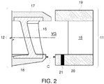
- stator 11 The position of the stator 11 relative to the runner 12 (dashed circle in Fig. 1 ) is shown in detail in Fig. 2 .
- Guide vane 15 of stator 11 extends in vertical direction between an upper stator ring 19 and a lower stator ring 20.
- Runner blades 16 extend in runner 12 between a runner crown 17 and a runner band 18. Between runner band 18 and the surrounding lower stator ring 20 there is a predetermined clearance C.
- the proposed sealing means comprises brush seals located at a radial distance from the rotor axis being a major proportion of the maximum radial dimension of the rotor.
- the disclosure aims at decreasing drastically the fluctuation level with an innovative, easy to set up and low-cost solution.
- Document EP 0 565 805 A1 discloses a system for controlling the pulses of hydraulic pressure and power in a reaction hydraulic turbine.
- the system comprises means for introducing an additional, controlled, pulsating flow of water at the diffusor elbow, consisting, together or alternatively, of a) at least one moveable body inside the diffusor between a first, retracted position and a second, extended position; b) at least one auxiliary duct which is markedly parallel to the diffusor and connected to the said diffusor with its own inlet and outlet apertures the inlet opening being positioned at the end of the diffusor elbow controlled by a valve and the outlet opening being positioned adjacent to the piezometric basin; the said moveable body and valve being controlled in such a way as to make the volume of the diffusor vary to reduce the pulses of pressure in the diffusor to a minimum and to maintain the flow, the gap, the torque, and the power of the rotor of the turbine constant.
- Exit Stay Apparatus for Francis and propeller hydraulic turbines.
- the purpose of the apparatus is to eliminate the loss of turbine efficiency and strong pulsations in draft tube caused by the axial circular vortex in all turbine operating regimes other than optimum without a noticeable decrease in maximum efficiency.
- the Exit Stay Apparatus has a crown and exit stay vanes secured to the crown. When installed in the turbine, the exit stay crown is located immediately after the runner crown, which is truncated at the bottom by a plane perpendicular to the central axis of the turbine. The exit stay crown together with the truncated runner crown forms water passages after the runner blade crown profile exit.
- exit stay vanes are arranged in a circular array around the turbine axis, located after the runner blades, and attached at the periphery either to the draft tube cone or to an exit stay flange secured to the turbine discharge ring and to the draft tube cone.
- Document WO 2008/060158 A2 relates to a hydraulic reaction turbine comprising a runner, a draft tube downstream of the runner, and injection means for introducing water into the draft tube in order to reduce pressure fluctuations therein, with one or more openings in the draft tube wall adapted to substantially evenly distribute injected water in the axial and/or circumferential direction of the draft tube.
- JP 55060666 which discloses a method of miniaturising a turbine
- JP 55051964 which discloses providing openings in the turbine to reduce water thrust
- JP 06074138 which discloses a system which seeks to reduce friction loss
- US 5290148 which is concerned with the thickness of a runner band and a crown, and rigidity in respect of structural matters.
- JP 55060666 provides an example of obtaining and manipulating geometric data for the inside diameter and width of a runner.
- the clearance is larger than found in the prior art.
- teaching of JP 55060666 is to reduce any clearance between the runner and the stator, which would have a detrimental effect on the pressure pulsations.
- Other modifications are provided in the prior art, but the impact of adjusting the clearance to minimize pressure pulsations is not considered.
- the present invention advantageously significantly increases the mechanical clearance between rotor and stator (runner and ring) compared to prior art standards.
- Fig. 3 the clearance C1 between runner (runner band 18) and stator (lower stator ring 20) is small in accordance with prior art practice.
- the relative motion between guide vanes 15 and runner blades 16 generates a pressure field with pressure pulsations 22 coming from guide vanes 15 and a respective pressure field coming from the runner blades 16 (arrows in Fig. 3(a) ).
- the interaction of both pressure fields increases the pressure (P(t) in Fig. 3(b) ), which can be measured by suitable pressure sensors 21.
- a respective clearance increase has been performed during the development tests of an actual project (nominal head of 305 m) and has shown impressive results on pressure fluctuations level on the whole range of head (see Fig. 6 ), especially at part load (0.5 on x-axis) where the level decreased from 20% to 10%.
- Fig. 5 shows crown clearance CC between upper stator ring 19 and runner crown 17 and band clearance CB between lower stator ring 20 and runner band 18. Although shown as equal in Fig. 5 , CC and CB may be different. Related to crown clearance CC is the crown radius RC. Related to band clearance CB is the band radius RB.
- CC/RC ratio CB/RB ratio
- ⁇ 0.012 the increase in clearance
- CC/RC ratio CB/RB ratio > 0.02 (tested 0.0224 and 0.0298).
- both ratios CC/RC and CB/RB need not be equal, but may differ, while both ratios are higher than 0.02 (CC/RC ⁇ CB/RB and CC/RC > 0.02 and CB/RB > 0.02).
- the ratio CC/RC between said first clearance CC and said first radius RC may be ⁇ 0.02, while the ratio CB/RB between said second clearance CB and said second radius RB may be ⁇ 0.02.
- the ratio CC/RC between said first clearance CC and said first radius RC may be ⁇ 0.02, while the ratio CB/RB between said second clearance CB and said second radius RB may be ⁇ 0.02.
- the size and location of the clearance may be dependent on the dimensions and shapes of the stator and rotor.
Landscapes
- Engineering & Computer Science (AREA)
- Chemical & Material Sciences (AREA)
- Combustion & Propulsion (AREA)
- Mechanical Engineering (AREA)
- General Engineering & Computer Science (AREA)
- Hydraulic Turbines (AREA)
- Turbine Rotor Nozzle Sealing (AREA)
Claims (7)
- Hydraulikturbine (10), umfassend:ein Laufrad (12), umfassend eine Laufradkrone (17), ein Laufradband (18) und eine Vielzahl von Laufradblättern (16), die sich zwischen der Laufradkrone (17) und dem Laufradband (18) erstrecken; undeinen Stator (11) der das Laufrad umgibt, wobei der Stator einen oberen Statorring (19), einen unteren Statorring (20) und eine Vielzahl von Leitschaufeln (15) umfasst, die sich zwischen dem oberen Statorring (19) und dem unteren Statorring (20) erstrecken; wobeiein Spielraum (C, C1, C2, CB, CC) zwischen dem Laufrad (12) und dem Stator (11) angeordnet ist, um Druckpulsationen (22) zu minimieren, die sich in einem schaufellosen Spalt (Vaneless Gap, VG) zwischen den Laufradblättern (16) des Laufrades (12) und den Leitschaufeln (15) des Stators (11) entwickeln; wobei der Spielraum (C, C1, C2, CB, CC) umfassteinen ersten Spielraum (CC) zwischen der Laufradkrone (17) und dem oberen Statorring (19), und ein erstes Verhältnis (CC/RC) zwischen dem ersten Spielraum (CC) und dem Radius (RC) der Laufradkrone (17) definiert ist,dadurch gekennzeichnet, dass das erste Verhältnis (CC/RC) größer oder gleich 0,02 ist.
- Hydraulikturbine nach Anspruch 1, dadurch gekennzeichnet, dass der Spielraum umfasst:
einen zweiten Spielraum (CB) zwischen dem Laufradband (18) und dem unteren Statorring (20), und ein zweites Verhältnis (CB/RB) zwischen dem zweiten Spielraum (CB) und dem Radius (RB) des Laufradbandes (18) definiert ist. - Hydraulikturbine nach Anspruch 2, dadurch gekennzeichnet, dass das zweite Verhältnis (CB/RB) 0,02 ist.
- Hydraulikturbine nach Anspruch 2, dadurch gekennzeichnet, dass das zweite Verhältnis (CB/RB) kleiner als 0,02 ist.
- Hydraulikturbine nach Anspruch 2, dadurch gekennzeichnet, dass das zweite Verhältnis (CB/RB) größer als 0,02 ist.
- Hydraulikturbine (10), umfassend:ein Laufrad (12), umfassend eine Laufradkrone (17), ein Laufradband (18) und eine Vielzahl von Laufradblättern (16), die sich zwischen der Laufradkrone (17) und dem Laufradband (18) erstrecken; undeinen Stator (11) der das Laufrad umgibt, wobei der Stator einen oberen Statorring (19), einen unteren Statorring (20) und eine Vielzahl von Leitschaufeln (15) umfasst, die sich zwischen dem oberen Statorring (19) und dem unteren Statorring (20) erstrecken;einen Spielraum (C, C1, C2, CB, CC) zwischen dem Laufrad (12) und dem Stator (11), der angeordnet ist, um Druckpulsationen (22) zu minimieren, die sich in einem schaufellosen Spalt (VG) zwischen den Laufradblättern (16) des Laufrades (12) und den Leitschaufeln (15) des Stators (11) entwickeln;wobei der Spielraum (C, C1, C2, CB, CC) umfassteinen ersten Spielraum (CC) zwischen der Laufradkrone (17) und dem oberen Statorring (19) und ein erstes Verhältnis (CC/RC) zwischen dem ersten Spielraum (CC) und dem Radius (RC) der Laufradkrone (17) definiert ist; undeinen zweiten Spielraum (CB) zwischen dem Laufradband (18) und dem unteren Statorring (20), und ein zweites Verhältnis (CB/RB) zwischen dem zweiten Spielraum (CB) und dem Radius (RB) des Laufradbandes (18) definiert istdadurch gekennzeichnet, dass das erste Verhältnis (CC/RC) kleiner oder gleich 0,02 ist und das zweite Verhältnis (CB/RB) größer oder gleich 0,02 ist.
- Hydraulikturbine nach einem der Ansprüche 2 bis 6, dadurch gekennzeichnet, dass das erste Verhältnis (CC/RC) im Wesentlichen gleich dem zweiten Verhältnis (CB/RB) ist.
Applications Claiming Priority (1)
| Application Number | Priority Date | Filing Date | Title |
|---|---|---|---|
| EP16290143.3A EP3276157A1 (de) | 2016-07-25 | 2016-07-25 | Wasserturbine |
Publications (2)
| Publication Number | Publication Date |
|---|---|
| EP3276158A1 EP3276158A1 (de) | 2018-01-31 |
| EP3276158B1 true EP3276158B1 (de) | 2019-11-13 |
Family
ID=56609827
Family Applications (2)
| Application Number | Title | Priority Date | Filing Date |
|---|---|---|---|
| EP16290143.3A Withdrawn EP3276157A1 (de) | 2016-07-25 | 2016-07-25 | Wasserturbine |
| EP17182724.9A Active EP3276158B1 (de) | 2016-07-25 | 2017-07-24 | Hydraulikturbine |
Family Applications Before (1)
| Application Number | Title | Priority Date | Filing Date |
|---|---|---|---|
| EP16290143.3A Withdrawn EP3276157A1 (de) | 2016-07-25 | 2016-07-25 | Wasserturbine |
Country Status (7)
| Country | Link |
|---|---|
| US (2) | US10480480B2 (de) |
| EP (2) | EP3276157A1 (de) |
| JP (1) | JP2018017234A (de) |
| CN (1) | CN107654329B (de) |
| ES (1) | ES2773998T3 (de) |
| PT (1) | PT3276158T (de) |
| RU (1) | RU2741358C2 (de) |
Families Citing this family (4)
| Publication number | Priority date | Publication date | Assignee | Title |
|---|---|---|---|---|
| EP3276157A1 (de) * | 2016-07-25 | 2018-01-31 | GE Renewable Technologies | Wasserturbine |
| JP7278985B2 (ja) * | 2020-03-05 | 2023-05-22 | 株式会社東芝 | フランシス型水車用ランナ及びフランシス型水車 |
| DE102021101197B3 (de) | 2021-01-21 | 2022-03-10 | Voith Patent Gmbh | Hydraulische Maschine vom Typ Francis |
| CN116624308B (zh) * | 2023-05-26 | 2026-01-13 | 中国长江电力股份有限公司 | 一种轴流转桨式机组导水机构更新改造端面间隙确定方法 |
Family Cites Families (33)
| Publication number | Priority date | Publication date | Assignee | Title |
|---|---|---|---|---|
| US2416268A (en) * | 1943-10-01 | 1947-02-18 | Allis Chalmers Mfg Co | Hydraulic turbine seal |
| GB1006300A (en) * | 1962-10-15 | 1965-09-29 | English Electric Co Ltd | Improvements in or relating to hydraulic pumps and reversible pump turbines |
| US3245656A (en) * | 1964-04-06 | 1966-04-12 | Dominion Eng Works Ltd | Automatic supply of sealing fluid for rotary fluid machines |
| US3360238A (en) * | 1967-02-13 | 1967-12-26 | Dominion Eng Works Ltd | Shroud seal for hydraulic machines |
| JPS5034640U (de) * | 1973-07-27 | 1975-04-14 | ||
| JPS5417B2 (de) * | 1974-09-27 | 1979-01-05 | ||
| JPS5337252A (en) * | 1976-09-17 | 1978-04-06 | Fuji Electric Co Ltd | Sealing arrangement between runner and fixed part of hydraulic machine |
| JPS605788B2 (ja) * | 1977-10-20 | 1985-02-14 | 株式会社東芝 | 水車ケーシング |
| JPS551964A (en) | 1978-06-21 | 1980-01-09 | Yuasa Battery Co Ltd | Method and apparatus for continuous casting of grating for lead storage battery |
| JPS5551964A (en) * | 1978-10-11 | 1980-04-16 | Hitachi Ltd | Hydraulic machine |
| JPS5560666A (en) * | 1978-10-31 | 1980-05-07 | Toshiba Corp | Runner for pump water turbine |
| US4286919A (en) * | 1979-12-13 | 1981-09-01 | Hitachi, Ltd. | Apparatus for pumping operation of a hydraulic machine having Francis type runner |
| JPS5838387A (ja) * | 1981-08-31 | 1983-03-05 | Toshiba Corp | フランシス形ポンプ水車 |
| JPS5875966U (ja) * | 1981-11-18 | 1983-05-23 | 株式会社日立製作所 | 水車ランナ−の漏水シ−ル装置 |
| JPS6022076A (ja) * | 1983-07-15 | 1985-02-04 | Toshiba Corp | 水力機械 |
| JPH0674138B2 (ja) | 1986-07-07 | 1994-09-21 | 雄一 村上 | ゼオライト細孔入口径の精密制御法 |
| JPH0723710B2 (ja) * | 1989-06-20 | 1995-03-15 | 株式会社東芝 | 水力機械及びその運転制御方法 |
| JPH0768935B2 (ja) * | 1991-03-13 | 1995-07-26 | 株式会社東芝 | 高落差ポンプ水車 |
| ATE145450T1 (de) | 1992-04-14 | 1996-12-15 | Ente Naz Energia Elettrica | Steuerung von druck- und leistungsschwankungen in wasserturbinen |
| JPH0674138A (ja) * | 1992-08-27 | 1994-03-15 | Hitachi Ltd | 水力機械のシール構造 |
| JP4884603B2 (ja) * | 2001-06-28 | 2012-02-29 | 三菱重工業株式会社 | ポンプ水車のランナ |
| AU2003281669A1 (en) * | 2002-07-26 | 2004-02-16 | Bernd Gapp | Composite material |
| US6918744B2 (en) | 2002-08-21 | 2005-07-19 | Alexander Gokhman | Hydraulic turbine and exit stay apparatus therefor |
| NO325031B1 (no) | 2006-07-04 | 2008-01-21 | Ge Energy Norway As | Vannturbin |
| NO325509B1 (no) | 2006-11-16 | 2008-05-26 | Ge Energy Norway As | Hydraulisk reaksjonsturbin og fremgangsmate for reduksjon av trykkfluktuasjoner |
| FR2925939A1 (fr) * | 2007-12-28 | 2009-07-03 | Alstom Power Hydraulique Sa | Machine hydraulique, installation de conversion d'energie comprenant une telle machine et procede d'ajustement d'une telle machine |
| CN101560940B (zh) * | 2009-05-27 | 2010-04-21 | 南京星飞冷却设备有限公司 | 应用于水动节能冷却塔的直联低速小型混流式水轮机 |
| CN101560936B (zh) * | 2009-05-27 | 2010-12-08 | 南京星飞冷却设备有限公司 | 水动节能型冷却塔直联低速小型混流式水轮机用转轮 |
| FR2974394A1 (fr) | 2011-04-20 | 2012-10-26 | Alstom Hydro France | Roue pour machine hydraulique, machine hydraulique equipee d'une telle roue et installation de conversion d'energie comprenant une telle machine hydraulique |
| CN103498749B (zh) * | 2013-09-27 | 2016-03-02 | 河海大学 | 一种用于低水头抽水蓄能电站的小型混流式水泵水轮机 |
| FR3016134B1 (fr) * | 2014-01-08 | 2016-04-15 | Alstom Renewable Technologies | Procede de fabrication d'une roue de type francis pour machine hydraulique et roue fabriquee par un tel procede |
| JP2016109087A (ja) * | 2014-12-09 | 2016-06-20 | 株式会社東芝 | 水力機械 |
| EP3276157A1 (de) * | 2016-07-25 | 2018-01-31 | GE Renewable Technologies | Wasserturbine |
-
2016
- 2016-07-25 EP EP16290143.3A patent/EP3276157A1/de not_active Withdrawn
-
2017
- 2017-07-20 US US15/655,166 patent/US10480480B2/en active Active
- 2017-07-20 JP JP2017140424A patent/JP2018017234A/ja active Pending
- 2017-07-24 PT PT171827249T patent/PT3276158T/pt unknown
- 2017-07-24 ES ES17182724T patent/ES2773998T3/es active Active
- 2017-07-24 EP EP17182724.9A patent/EP3276158B1/de active Active
- 2017-07-25 CN CN201710611090.1A patent/CN107654329B/zh active Active
- 2017-07-25 RU RU2017126542A patent/RU2741358C2/ru active
-
2019
- 2019-11-18 US US16/686,835 patent/US11073124B2/en active Active
Non-Patent Citations (1)
| Title |
|---|
| None * |
Also Published As
| Publication number | Publication date |
|---|---|
| US11073124B2 (en) | 2021-07-27 |
| CN107654329B (zh) | 2021-06-08 |
| ES2773998T3 (es) | 2020-07-16 |
| US10480480B2 (en) | 2019-11-19 |
| RU2017126542A (ru) | 2019-01-25 |
| PT3276158T (pt) | 2020-02-20 |
| US20200149505A1 (en) | 2020-05-14 |
| EP3276158A1 (de) | 2018-01-31 |
| RU2741358C2 (ru) | 2021-01-25 |
| CN107654329A (zh) | 2018-02-02 |
| US20180023534A1 (en) | 2018-01-25 |
| RU2017126542A3 (de) | 2020-08-07 |
| EP3276157A1 (de) | 2018-01-31 |
| JP2018017234A (ja) | 2018-02-01 |
Similar Documents
| Publication | Publication Date | Title |
|---|---|---|
| US11073124B2 (en) | Hydraulic turbine | |
| EP3018297B1 (de) | Abdichtungsvorrichtung und turbomaschine | |
| US6129507A (en) | Method and device for reducing axial thrust in rotary machines and a centrifugal pump using same | |
| US8475125B2 (en) | Shroud vortex remover | |
| EP2453111A2 (de) | Labyrinthdichtungen für Turbomaschinen | |
| JP2003013898A (ja) | 軸流形流体機械 | |
| US11149588B2 (en) | Exhaust chamber of steam turbine, flow guide for steam turbine exhaust chamber, and steam turbine | |
| EP2634376A2 (de) | Turbomaschinendichtungsanordnung | |
| CN113389601B (zh) | 一种叶顶带有孔腔的倾斜螺旋槽密封结构及叶轮机械 | |
| JP5850805B2 (ja) | 蒸気タービンの排気室およびその製造方法 | |
| US8425181B2 (en) | Axial-flow turbine with flow extraction means | |
| US8916986B2 (en) | Impulse air turbine arrangement for use with a reversing bi-directional air flow in a wave power plant | |
| US5125794A (en) | Impulse turbine stage with reduced secondary losses | |
| JP2014034885A (ja) | 水中モータポンプ | |
| CN103732909B (zh) | 弗兰西斯水轮机或弗兰西斯泵或弗兰西斯水泵水轮机 | |
| JP3617606B2 (ja) | インターナルポンプ | |
| JP2005171828A (ja) | フランシス型ランナ | |
| RU2290516C1 (ru) | Выхлопной патрубок паровой турбины | |
| JP2022077917A (ja) | 水力機械 | |
| RO135938B1 (ro) | Echipament pentru eliminarea instabilităţilor generate de curgerea cu vârtej din difuzorul conic al turbinelor hidraulice | |
| JP2020037904A (ja) | 軸流タービン | |
| JP2013019289A (ja) | 水力機械 |
Legal Events
| Date | Code | Title | Description |
|---|---|---|---|
| PUAI | Public reference made under article 153(3) epc to a published international application that has entered the european phase |
Free format text: ORIGINAL CODE: 0009012 |
|
| STAA | Information on the status of an ep patent application or granted ep patent |
Free format text: STATUS: THE APPLICATION HAS BEEN PUBLISHED |
|
| AK | Designated contracting states |
Kind code of ref document: A1 Designated state(s): AL AT BE BG CH CY CZ DE DK EE ES FI FR GB GR HR HU IE IS IT LI LT LU LV MC MK MT NL NO PL PT RO RS SE SI SK SM TR |
|
| AX | Request for extension of the european patent |
Extension state: BA ME |
|
| STAA | Information on the status of an ep patent application or granted ep patent |
Free format text: STATUS: REQUEST FOR EXAMINATION WAS MADE |
|
| 17P | Request for examination filed |
Effective date: 20180803 |
|
| RBV | Designated contracting states (corrected) |
Designated state(s): AL AT BE BG CH CY CZ DE DK EE ES FI FR GB GR HR HU IE IS IT LI LT LU LV MC MK MT NL NO PL PT RO RS SE SI SK SM TR |
|
| GRAP | Despatch of communication of intention to grant a patent |
Free format text: ORIGINAL CODE: EPIDOSNIGR1 |
|
| STAA | Information on the status of an ep patent application or granted ep patent |
Free format text: STATUS: GRANT OF PATENT IS INTENDED |
|
| INTG | Intention to grant announced |
Effective date: 20190513 |
|
| GRAS | Grant fee paid |
Free format text: ORIGINAL CODE: EPIDOSNIGR3 |
|
| GRAJ | Information related to disapproval of communication of intention to grant by the applicant or resumption of examination proceedings by the epo deleted |
Free format text: ORIGINAL CODE: EPIDOSDIGR1 |
|
| GRAL | Information related to payment of fee for publishing/printing deleted |
Free format text: ORIGINAL CODE: EPIDOSDIGR3 |
|
| STAA | Information on the status of an ep patent application or granted ep patent |
Free format text: STATUS: REQUEST FOR EXAMINATION WAS MADE |
|
| GRAR | Information related to intention to grant a patent recorded |
Free format text: ORIGINAL CODE: EPIDOSNIGR71 |
|
| STAA | Information on the status of an ep patent application or granted ep patent |
Free format text: STATUS: GRANT OF PATENT IS INTENDED |
|
| GRAA | (expected) grant |
Free format text: ORIGINAL CODE: 0009210 |
|
| STAA | Information on the status of an ep patent application or granted ep patent |
Free format text: STATUS: THE PATENT HAS BEEN GRANTED |
|
| INTC | Intention to grant announced (deleted) | ||
| AK | Designated contracting states |
Kind code of ref document: B1 Designated state(s): AL AT BE BG CH CY CZ DE DK EE ES FI FR GB GR HR HU IE IS IT LI LT LU LV MC MK MT NL NO PL PT RO RS SE SI SK SM TR |
|
| INTG | Intention to grant announced |
Effective date: 20191008 |
|
| REG | Reference to a national code |
Ref country code: CH Ref legal event code: EP Ref country code: AT Ref legal event code: REF Ref document number: 1201913 Country of ref document: AT Kind code of ref document: T Effective date: 20191115 |
|
| REG | Reference to a national code |
Ref country code: DE Ref legal event code: R096 Ref document number: 602017008611 Country of ref document: DE |
|
| REG | Reference to a national code |
Ref country code: IE Ref legal event code: FG4D |
|
| REG | Reference to a national code |
Ref country code: CH Ref legal event code: NV Representative=s name: VALIPAT S.A. C/O BOVARD SA NEUCHATEL, CH |
|
| REG | Reference to a national code |
Ref country code: PT Ref legal event code: SC4A Ref document number: 3276158 Country of ref document: PT Date of ref document: 20200220 Kind code of ref document: T Free format text: AVAILABILITY OF NATIONAL TRANSLATION Effective date: 20200210 |
|
| REG | Reference to a national code |
Ref country code: NL Ref legal event code: MP Effective date: 20191113 |
|
| REG | Reference to a national code |
Ref country code: NO Ref legal event code: T2 Effective date: 20191113 |
|
| REG | Reference to a national code |
Ref country code: LT Ref legal event code: MG4D |
|
| PG25 | Lapsed in a contracting state [announced via postgrant information from national office to epo] |
Ref country code: LT Free format text: LAPSE BECAUSE OF FAILURE TO SUBMIT A TRANSLATION OF THE DESCRIPTION OR TO PAY THE FEE WITHIN THE PRESCRIBED TIME-LIMIT Effective date: 20191113 Ref country code: GR Free format text: LAPSE BECAUSE OF FAILURE TO SUBMIT A TRANSLATION OF THE DESCRIPTION OR TO PAY THE FEE WITHIN THE PRESCRIBED TIME-LIMIT Effective date: 20200214 Ref country code: PL Free format text: LAPSE BECAUSE OF FAILURE TO SUBMIT A TRANSLATION OF THE DESCRIPTION OR TO PAY THE FEE WITHIN THE PRESCRIBED TIME-LIMIT Effective date: 20191113 Ref country code: SE Free format text: LAPSE BECAUSE OF FAILURE TO SUBMIT A TRANSLATION OF THE DESCRIPTION OR TO PAY THE FEE WITHIN THE PRESCRIBED TIME-LIMIT Effective date: 20191113 Ref country code: LV Free format text: LAPSE BECAUSE OF FAILURE TO SUBMIT A TRANSLATION OF THE DESCRIPTION OR TO PAY THE FEE WITHIN THE PRESCRIBED TIME-LIMIT Effective date: 20191113 Ref country code: FI Free format text: LAPSE BECAUSE OF FAILURE TO SUBMIT A TRANSLATION OF THE DESCRIPTION OR TO PAY THE FEE WITHIN THE PRESCRIBED TIME-LIMIT Effective date: 20191113 Ref country code: BG Free format text: LAPSE BECAUSE OF FAILURE TO SUBMIT A TRANSLATION OF THE DESCRIPTION OR TO PAY THE FEE WITHIN THE PRESCRIBED TIME-LIMIT Effective date: 20200213 Ref country code: NL Free format text: LAPSE BECAUSE OF FAILURE TO SUBMIT A TRANSLATION OF THE DESCRIPTION OR TO PAY THE FEE WITHIN THE PRESCRIBED TIME-LIMIT Effective date: 20191113 |
|
| PG25 | Lapsed in a contracting state [announced via postgrant information from national office to epo] |
Ref country code: IS Free format text: LAPSE BECAUSE OF FAILURE TO SUBMIT A TRANSLATION OF THE DESCRIPTION OR TO PAY THE FEE WITHIN THE PRESCRIBED TIME-LIMIT Effective date: 20200313 Ref country code: HR Free format text: LAPSE BECAUSE OF FAILURE TO SUBMIT A TRANSLATION OF THE DESCRIPTION OR TO PAY THE FEE WITHIN THE PRESCRIBED TIME-LIMIT Effective date: 20191113 Ref country code: RS Free format text: LAPSE BECAUSE OF FAILURE TO SUBMIT A TRANSLATION OF THE DESCRIPTION OR TO PAY THE FEE WITHIN THE PRESCRIBED TIME-LIMIT Effective date: 20191113 |
|
| PG25 | Lapsed in a contracting state [announced via postgrant information from national office to epo] |
Ref country code: AL Free format text: LAPSE BECAUSE OF FAILURE TO SUBMIT A TRANSLATION OF THE DESCRIPTION OR TO PAY THE FEE WITHIN THE PRESCRIBED TIME-LIMIT Effective date: 20191113 |
|
| REG | Reference to a national code |
Ref country code: ES Ref legal event code: FG2A Ref document number: 2773998 Country of ref document: ES Kind code of ref document: T3 Effective date: 20200716 |
|
| PG25 | Lapsed in a contracting state [announced via postgrant information from national office to epo] |
Ref country code: RO Free format text: LAPSE BECAUSE OF FAILURE TO SUBMIT A TRANSLATION OF THE DESCRIPTION OR TO PAY THE FEE WITHIN THE PRESCRIBED TIME-LIMIT Effective date: 20191113 Ref country code: CZ Free format text: LAPSE BECAUSE OF FAILURE TO SUBMIT A TRANSLATION OF THE DESCRIPTION OR TO PAY THE FEE WITHIN THE PRESCRIBED TIME-LIMIT Effective date: 20191113 Ref country code: EE Free format text: LAPSE BECAUSE OF FAILURE TO SUBMIT A TRANSLATION OF THE DESCRIPTION OR TO PAY THE FEE WITHIN THE PRESCRIBED TIME-LIMIT Effective date: 20191113 Ref country code: DK Free format text: LAPSE BECAUSE OF FAILURE TO SUBMIT A TRANSLATION OF THE DESCRIPTION OR TO PAY THE FEE WITHIN THE PRESCRIBED TIME-LIMIT Effective date: 20191113 |
|
| REG | Reference to a national code |
Ref country code: DE Ref legal event code: R097 Ref document number: 602017008611 Country of ref document: DE |
|
| PG25 | Lapsed in a contracting state [announced via postgrant information from national office to epo] |
Ref country code: SM Free format text: LAPSE BECAUSE OF FAILURE TO SUBMIT A TRANSLATION OF THE DESCRIPTION OR TO PAY THE FEE WITHIN THE PRESCRIBED TIME-LIMIT Effective date: 20191113 Ref country code: SK Free format text: LAPSE BECAUSE OF FAILURE TO SUBMIT A TRANSLATION OF THE DESCRIPTION OR TO PAY THE FEE WITHIN THE PRESCRIBED TIME-LIMIT Effective date: 20191113 |
|
| PLBE | No opposition filed within time limit |
Free format text: ORIGINAL CODE: 0009261 |
|
| STAA | Information on the status of an ep patent application or granted ep patent |
Free format text: STATUS: NO OPPOSITION FILED WITHIN TIME LIMIT |
|
| 26N | No opposition filed |
Effective date: 20200814 |
|
| PG25 | Lapsed in a contracting state [announced via postgrant information from national office to epo] |
Ref country code: SI Free format text: LAPSE BECAUSE OF FAILURE TO SUBMIT A TRANSLATION OF THE DESCRIPTION OR TO PAY THE FEE WITHIN THE PRESCRIBED TIME-LIMIT Effective date: 20191113 |
|
| PG25 | Lapsed in a contracting state [announced via postgrant information from national office to epo] |
Ref country code: IT Free format text: LAPSE BECAUSE OF FAILURE TO SUBMIT A TRANSLATION OF THE DESCRIPTION OR TO PAY THE FEE WITHIN THE PRESCRIBED TIME-LIMIT Effective date: 20191113 |
|
| PG25 | Lapsed in a contracting state [announced via postgrant information from national office to epo] |
Ref country code: MC Free format text: LAPSE BECAUSE OF FAILURE TO SUBMIT A TRANSLATION OF THE DESCRIPTION OR TO PAY THE FEE WITHIN THE PRESCRIBED TIME-LIMIT Effective date: 20191113 |
|
| REG | Reference to a national code |
Ref country code: BE Ref legal event code: MM Effective date: 20200731 |
|
| PG25 | Lapsed in a contracting state [announced via postgrant information from national office to epo] |
Ref country code: LU Free format text: LAPSE BECAUSE OF NON-PAYMENT OF DUE FEES Effective date: 20200724 Ref country code: FR Free format text: LAPSE BECAUSE OF NON-PAYMENT OF DUE FEES Effective date: 20200731 |
|
| PG25 | Lapsed in a contracting state [announced via postgrant information from national office to epo] |
Ref country code: BE Free format text: LAPSE BECAUSE OF NON-PAYMENT OF DUE FEES Effective date: 20200731 |
|
| PG25 | Lapsed in a contracting state [announced via postgrant information from national office to epo] |
Ref country code: IE Free format text: LAPSE BECAUSE OF NON-PAYMENT OF DUE FEES Effective date: 20200724 |
|
| REG | Reference to a national code |
Ref country code: AT Ref legal event code: UEP Ref document number: 1201913 Country of ref document: AT Kind code of ref document: T Effective date: 20191113 |
|
| GBPC | Gb: european patent ceased through non-payment of renewal fee |
Effective date: 20210724 |
|
| PG25 | Lapsed in a contracting state [announced via postgrant information from national office to epo] |
Ref country code: GB Free format text: LAPSE BECAUSE OF NON-PAYMENT OF DUE FEES Effective date: 20210724 |
|
| PG25 | Lapsed in a contracting state [announced via postgrant information from national office to epo] |
Ref country code: MT Free format text: LAPSE BECAUSE OF FAILURE TO SUBMIT A TRANSLATION OF THE DESCRIPTION OR TO PAY THE FEE WITHIN THE PRESCRIBED TIME-LIMIT Effective date: 20191113 Ref country code: CY Free format text: LAPSE BECAUSE OF FAILURE TO SUBMIT A TRANSLATION OF THE DESCRIPTION OR TO PAY THE FEE WITHIN THE PRESCRIBED TIME-LIMIT Effective date: 20191113 |
|
| PG25 | Lapsed in a contracting state [announced via postgrant information from national office to epo] |
Ref country code: MK Free format text: LAPSE BECAUSE OF FAILURE TO SUBMIT A TRANSLATION OF THE DESCRIPTION OR TO PAY THE FEE WITHIN THE PRESCRIBED TIME-LIMIT Effective date: 20191113 |
|
| P01 | Opt-out of the competence of the unified patent court (upc) registered |
Effective date: 20230522 |
|
| PGFP | Annual fee paid to national office [announced via postgrant information from national office to epo] |
Ref country code: NO Payment date: 20250623 Year of fee payment: 9 |
|
| PGFP | Annual fee paid to national office [announced via postgrant information from national office to epo] |
Ref country code: PT Payment date: 20250624 Year of fee payment: 9 |
|
| PGFP | Annual fee paid to national office [announced via postgrant information from national office to epo] |
Ref country code: TR Payment date: 20250627 Year of fee payment: 9 |
|
| PGFP | Annual fee paid to national office [announced via postgrant information from national office to epo] |
Ref country code: ES Payment date: 20250801 Year of fee payment: 9 |
|
| PGFP | Annual fee paid to national office [announced via postgrant information from national office to epo] |
Ref country code: DE Payment date: 20250620 Year of fee payment: 9 |
|
| PGFP | Annual fee paid to national office [announced via postgrant information from national office to epo] |
Ref country code: AT Payment date: 20250623 Year of fee payment: 9 |
|
| PGFP | Annual fee paid to national office [announced via postgrant information from national office to epo] |
Ref country code: CH Payment date: 20250801 Year of fee payment: 9 |