EP3273512A1 - Lead storage cell - Google Patents
Lead storage cell Download PDFInfo
- Publication number
- EP3273512A1 EP3273512A1 EP15885338.2A EP15885338A EP3273512A1 EP 3273512 A1 EP3273512 A1 EP 3273512A1 EP 15885338 A EP15885338 A EP 15885338A EP 3273512 A1 EP3273512 A1 EP 3273512A1
- Authority
- EP
- European Patent Office
- Prior art keywords
- negative electrode
- negative
- electrode plate
- positive
- alloy
- Prior art date
- Legal status (The legal status is an assumption and is not a legal conclusion. Google has not performed a legal analysis and makes no representation as to the accuracy of the status listed.)
- Granted
Links
Images

Classifications
-
- H—ELECTRICITY
- H01—ELECTRIC ELEMENTS
- H01M—PROCESSES OR MEANS, e.g. BATTERIES, FOR THE DIRECT CONVERSION OF CHEMICAL ENERGY INTO ELECTRICAL ENERGY
- H01M4/00—Electrodes
- H01M4/02—Electrodes composed of, or comprising, active material
- H01M4/64—Carriers or collectors
- H01M4/70—Carriers or collectors characterised by shape or form
- H01M4/72—Grids
- H01M4/73—Grids for lead-acid accumulators, e.g. frame plates
-
- H—ELECTRICITY
- H01—ELECTRIC ELEMENTS
- H01M—PROCESSES OR MEANS, e.g. BATTERIES, FOR THE DIRECT CONVERSION OF CHEMICAL ENERGY INTO ELECTRICAL ENERGY
- H01M10/00—Secondary cells; Manufacture thereof
- H01M10/06—Lead-acid accumulators
- H01M10/08—Selection of materials as electrolytes
-
- H—ELECTRICITY
- H01—ELECTRIC ELEMENTS
- H01M—PROCESSES OR MEANS, e.g. BATTERIES, FOR THE DIRECT CONVERSION OF CHEMICAL ENERGY INTO ELECTRICAL ENERGY
- H01M4/00—Electrodes
- H01M4/02—Electrodes composed of, or comprising, active material
- H01M4/64—Carriers or collectors
- H01M4/66—Selection of materials
- H01M4/68—Selection of materials for use in lead-acid accumulators
- H01M4/685—Lead alloys
-
- H—ELECTRICITY
- H01—ELECTRIC ELEMENTS
- H01M—PROCESSES OR MEANS, e.g. BATTERIES, FOR THE DIRECT CONVERSION OF CHEMICAL ENERGY INTO ELECTRICAL ENERGY
- H01M50/00—Constructional details or processes of manufacture of the non-active parts of electrochemical cells other than fuel cells, e.g. hybrid cells
- H01M50/50—Current conducting connections for cells or batteries
- H01M50/531—Electrode connections inside a battery casing
- H01M50/534—Electrode connections inside a battery casing characterised by the material of the leads or tabs
-
- Y—GENERAL TAGGING OF NEW TECHNOLOGICAL DEVELOPMENTS; GENERAL TAGGING OF CROSS-SECTIONAL TECHNOLOGIES SPANNING OVER SEVERAL SECTIONS OF THE IPC; TECHNICAL SUBJECTS COVERED BY FORMER USPC CROSS-REFERENCE ART COLLECTIONS [XRACs] AND DIGESTS
- Y02—TECHNOLOGIES OR APPLICATIONS FOR MITIGATION OR ADAPTATION AGAINST CLIMATE CHANGE
- Y02E—REDUCTION OF GREENHOUSE GAS [GHG] EMISSIONS, RELATED TO ENERGY GENERATION, TRANSMISSION OR DISTRIBUTION
- Y02E60/00—Enabling technologies; Technologies with a potential or indirect contribution to GHG emissions mitigation
- Y02E60/10—Energy storage using batteries
-
- Y—GENERAL TAGGING OF NEW TECHNOLOGICAL DEVELOPMENTS; GENERAL TAGGING OF CROSS-SECTIONAL TECHNOLOGIES SPANNING OVER SEVERAL SECTIONS OF THE IPC; TECHNICAL SUBJECTS COVERED BY FORMER USPC CROSS-REFERENCE ART COLLECTIONS [XRACs] AND DIGESTS
- Y02—TECHNOLOGIES OR APPLICATIONS FOR MITIGATION OR ADAPTATION AGAINST CLIMATE CHANGE
- Y02P—CLIMATE CHANGE MITIGATION TECHNOLOGIES IN THE PRODUCTION OR PROCESSING OF GOODS
- Y02P70/00—Climate change mitigation technologies in the production process for final industrial or consumer products
- Y02P70/50—Manufacturing or production processes characterised by the final manufactured product
Definitions
- the present invention relates to a lead acid battery for car starter.
- current collecting tabs (ears) of the positive electrode plates are collectively integrated with a positive strap for each electrode plate group
- current collecting tabs (ears) of the negative electrode plates are collectively integrated with a negative strap for each electrode plate group. More specifically, while the positive and the negative strap is being formed, the strap is integrated with the current collecting tabs (ears)by, for example, abutting a piece of lead alloy to the current collecting tabs (ears) and then heating them with a burner, or dipping the current collecting tabs (ears) in a molten lead alloy and then cooling and solidifying them.
- Patent Literatures 1 and 2 teach to provide bismuth (lead-bismuth alloy) at the boundaries between the positive strap and the current collecting tabs (ears) and between the negative strap and the current collecting tabs (ears).
- providing bismuth (lead-bismuth alloy) at the boundary between the negative strap and the current collecting tabs (ears) as taught by Patent Literature 1 unlike providing tin (lead-tin alloy), can suppress the occurrence of electrical disconnection due to corrosion, even though the boundary has been exposed from the surface of electrolyte as the electrolyte decreases with repetition of charge and discharge.
- Patent Literature 1 It is sometimes observed, however, that providing bismuth, for example, at the boundary between the negative strap and the current collecting tabs (ears) as taught by Patent Literature 1causes a different problem from the aforementioned problem of corrosion at the boundary, i.e., a reduction in charge acceptance.
- the present invention is made in view of the above, and aims to provide a highly reliable lead acid battery capable of suppressing the occurrence of reduction in charge acceptance and electrical disconnection due to corrosion that occur in association with decrease of electrolyte.
- a lead acid battery includes: positive electrode plates each including a positive electrode grid and a positive electrode active material, and negative electrode plates each including a negative electrode grid and a negative electrode active material, the positive electrode plate sand the negative electrode plates being stacked alternately with a separator between the positive electrode plate and the negative electrode plate to form an electrode plate group.
- the lead acid battery further includes: a positive strap integrated with current collecting tabs (ears) of the positive electrode plates collectively for each electrode plate group; a negative strap integrated with current collecting tabs (ears) of the negative electrode plates collectively for each electrode plate group; a battery container having a plurality of cell chambers each containing the electrode plate group and an electrolyte; and a cover sealing an opening of the battery container.
- a boundary layer containing bismuth is provided at a boundary between the current collecting tab (ear) of the negative electrode plate and the negative strap.
- the negative electrode grid comprises a lead-calcium-tin alloy containing tin in an amount of 0.45 mass% or less.
- the boundary layer comprises a lead-bismuth alloy, and preferably contains bismuth in an amount of 25 mass% or more and 50 mass% or less.
- the electrolyte contains aluminum ion at a concentration of 0.02 mol/L or more and 0.2 mol/L or less.
- the present invention it is possible to provide a highly reliable lead acid battery capable of suppressing the occurrence of reduction in charge acceptance and electrical disconnection due to corrosion that occur in association with decrease of electrolyte.
- FIG. 1 is a schematic overview of a lead acid battery of the present invention.
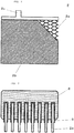
- FIG. 2 is an exemplary view of a negative electrode plate, an essential part of the lead acid battery of the present invention.
- FIG. 3 is an exemplary view of a boundary between the current collecting tab (ear) of the negative electrode plate and the negative strap, another essential part of the lead acid battery of the present invention.
- a plurality of electrode plate groups 4 each including positive electrode plates 1 and negative electrode plates 2 stacked alternately one on another with a separator 3 therebetween is placed in a battery container 5 having a plurality of cell chambers 5a, together with an electrolyte (not shown).
- Current collecting tabs (ears) 1c each serving as a current collecting portion projecting from the positive electrode plate 1 having an approximate rectangular outline when viewed from the front are collectively integrated with a positive strap 7for each electrode plate group 4.
- Current collecting tabs (ears) 2c each serving as a current collecting portion projecting from the negative electrode plate 2 having an approximate rectangular outline when viewed from the front are collectively integrated with a negative strap 8for each electrode plate group 4.
- the opening of the battery container 5 is sealed with a cover 6.
- the positive electrode plate 1 includes a positive electrode grid 1a and a positive electrode active material 1b
- the negative electrode plate 2 includes a negative electrode grid 2aand a negative electrode active material 2b.
- the present invention includes two features. The first is that a boundary layer 9 containing bismuth is provided at the boundary between the current collecting tab (ear) 2c of the negative electrode plate 2 and the negative strap 8. The second is that the negative electrode grid 2a comprises a lead-calcium-tin alloy containing tin in an amount of 0.45 mass% or less.
- the inventors have conceived of shifting the initial potential of the negative electrode grid 2a in the base direction, thereby to offset the influence of the potential shift due to the boundary layer 9 in the noble direction.
- the inventors have conducted intensive studies and found that the offset can be effectively and smoothly achieved by using a lead-calcium-tin alloy containing tin in an amount of 0.45 mass% or less for the negative electrode grid 2a.
- the amount of tin contained in the lead-calcium-tin alloy used for the negative electrode grid 2a exceeds 0.45 mass%, the potential of the negative electrode grid 2a itself extremely-shifts in the noble direction. This, in synergy with the effect of bismuth in the boundary layer 9, will excessively facilitate the-hydrolysis in the late stage of charging. As a result, the mobility of the electrolyte is reduced, failing to improve the charge acceptance.
- the amount of tin is reduced to or below the detection limit, the mechanical strength of the negative electrode grid 2a is reduced. This leads to deterioration in productivity. For example, when the negative electrode grid 2a is an expanded grid, the grid bone is prone to fracture in expanding process. Whatever the form of the negative electrode grid 2a is, the grid bone easily deforms when the negative electrode active material 2b is applied to the negative electrode grid 2a.
- the boundary layer 9 preferably comprises a lead-bismuth alloy, and preferably contains bismuth in an amount of 25 mass% or more and 50 mass% or less.
- the boundary layer 9 comprising a lead-bismuth alloy contains bismuth in an amount of below 25 mass%, the melting point of the layer exceeds 250°C and reaches near 330°C which is the melting point of the negative electrode grid 2a(lead-calcium-tin alloy). In this case, it becomes rather difficult for the boundary layer 9 to exert an effect similar to solder, and the advantage of providing the boundary layer 9, i.e., the prevention of disconnection due to corrosion, is somewhat reduced.
- the amount of bismuth in the boundary layer 9 can be determined by analyzing the portion provided in excess in the boundary layer 9, avoiding the portion where the bismuth has been spread during the welding with the negative strap 8.
- the amount of bismuth in the boundary layer 9 can be determined by analyzing the negative strap 8 itself.
- the lead acid battery to be mounted in the car equipped with ISS is required to have excellent charge acceptance (quick recovery ofSOC) as discussed above.
- allowing the electrolyte to include aluminum in the electrolyte at a concentration of 0.02 mol/L or more can realize the excellent charge acceptance.
- including aluminum in excess makes the charge acceptance insufficient.
- the upper limit of the aluminum concentration in the electrolyte is preferably 0.2 mol/L.
- a D26L-size lead acid battery specified in JISD5301 was fabricated in the present Examples.
- Cell chambers 5a each accommodate seven positive electrode plates 1 and eight negative electrode plates 2, with the negative electrode plates 2 each placed inside a bag-shaped separator 3 made of polyethylene.
- the positive electrode plate 1 was obtained by kneading a lead oxide powder with sulfuric acid and purified water, to prepare a precursor paste of a positive electrode active material 1b, and filling the paste into a positive electrode grid 1a (expanded grid) made of a lead alloy sheet containing calcium.
- the negative electrode plate 2 was obtained by adding carbon and an organic additive to a lead oxide powder, and kneading the powder with sulfuric acid and purified water, to prepare a precursor paste of a negative electrode active material 2b, and filling the paste into a negative electrode grid 2a (expanded grid) made of a lead alloy sheet having a composition as shown in Table 1.
- the obtained positive and negative electrode plates 1 and 2 were aged and dried. Afterwards, the negative electrode plates 2 were each placed inside the bag-shaped separator 3 made of polyethylene, and stacked with the positive electrode plates 2 alternately, to obtain an electrode plate group 4 comprising seven positive electrode plates 1 and eight negative electrode plates 2 stacked alternately one on another with the separator 3 therebetween. The electrode plate group 4 was placed in each of six cell chambers 5a divided by a partition.
- current collecting tabs (ears) 1c of the positive electrode plates 1 were collectively integrated with a positive strap 7 made of a lead-antimony alloy for each electrode plate group 4, and current collecting tabs (ears) 2c of the negative electrode plates 2 were collectively integrated with a negative strap 8 made of a lead-tin alloy for each electrode plate group 4.
- the positive strap 7 and the negative strap 8 in the cell chambers 5a adjacent to each other were connected in series.
- a foil was attached so that the current collecting tabs (ears) 2c of the negative electrode plates 2 were each provided with a boundary layer 9 as shown in Table 1.
- Batteries of Examples and Comparative Examples were each subjected to a charge acceptance test specified in JISD5301. Specifically, the battery was discharged at a5-hour rate for 2.5 hours in a 25°C environment, and after left to stand for 12 hours or more in a 0°C environment, subjected to a constant voltage charging at 14.4 V(maximum current: 100 A) for 10 minutes in a 0°C environment.
- the charge current value at the 10 th minute is shown in Table 1 as an index of the charge acceptance.
- the productivity was evaluated by the occurrence rate of grid bone fracture that occurred when lead alloy sheets having different compositions as shown in Table 1 were worked into the negative electrode grids 2a by the reciprocal expanding method of pressing the sheet with the die moving up and down. Specifically, during the production of the negative electrode plate 2, if the grid bone forming the network of the negative electrode grid 2a fractured at at least one point (electrical connection was broken), it was regarded as a defective, and the number of defectives in 10,000 negative electrode plates 2 produced was calculated as a percentage. The percentage is shown in Table 1 as an index of the productivity (the smaller the percentage is, the better the productivity is).
- the liquid level of electrolyte was set 5 mm below the bottom of the negative strap 8, thereby to expose the negative strap 8 from the electrolyte.
- the battery was subjected to a constant voltage charging at a charge voltage of 14.5 V (maximum current: 25 A) for 200 hours in a 70°C environment under the conditions of, as the vibration simulating actual car running, "vibration direction: vertical", “acceleration: 1 G”, and "sweep frequency:10Hz to 33Hz". Thereafter, the battery was disassembled to visually inspect the condition of the negative strap 8.
- Batteries A-1 to A-7 Comparison is made to Batteries A-1 to A-7.
- the productivity of the negative electrode grid 2a was significantly deteriorated; whereas, in Battery A-7 in which the amount of tin in the negative electrode grid 2a was above 0.45 mass%, the charge acceptance was extremely lowered.
- the negative electrode grid 2a desirably contains 0.45 mass% or less of tin.
- the amount of tin in the negative electrode grid 2a is 0.15 mass% or more and 0.35 mass% or less.
- Batteries C-1 to C-7 Comparison is made to Batteries C-1 to C-7.
- the charge acceptance was somewhat lowered. This indicates that the aluminum ion concentration in the electrolyte is preferably 0.02 mol/L or more and 0.2 mol/L or less.
- the present invention is described above by way of preferable embodiments, such description should not be construed as limiting the invention, and various variations are possible.
- the boundary layer 9 was attached to the current collecting tab (ear) 2c of the negative electrode plate 2in Examples
- the negative strap 8 itself can be made to have the same composition as the boundary layer 9 (i.e., the boundary layer 9 substantially constitutes a portion of the negative strap 8 abutting the current collecting tab (ear) 2c), with a similar tendency to the present Examples.
- the present invention can be usefully applied to the lead acid battery used in the car equipped with idling stop system.
Landscapes
- Chemical & Material Sciences (AREA)
- Chemical Kinetics & Catalysis (AREA)
- Electrochemistry (AREA)
- General Chemical & Material Sciences (AREA)
- Engineering & Computer Science (AREA)
- Materials Engineering (AREA)
- Manufacturing & Machinery (AREA)
- Connection Of Batteries Or Terminals (AREA)
- Cell Electrode Carriers And Collectors (AREA)
- Secondary Cells (AREA)
Abstract
Description
- The present invention relates to a lead acid battery for car starter.
- In the process of producing a lead acid battery, after production of electrode plate groups each including positive and negative electrode plates stacked alternately with a separator therebetween, current collecting tabs (ears) of the positive electrode plates are collectively integrated with a positive strap for each electrode plate group, and current collecting tabs (ears) of the negative electrode plates are collectively integrated with a negative strap for each electrode plate group. More specifically, while the positive and the negative strap is being formed, the strap is integrated with the current collecting tabs (ears)by, for example, abutting a piece of lead alloy to the current collecting tabs (ears) and then heating them with a burner, or dipping the current collecting tabs (ears) in a molten lead alloy and then cooling and solidifying them.
- To increase the affinity between the positive and the negative strap and the current collecting tabs (ears) so that they can be integrated smoothly,
Patent Literatures 1 and 2 teach to provide bismuth (lead-bismuth alloy) at the boundaries between the positive strap and the current collecting tabs (ears) and between the negative strap and the current collecting tabs (ears). In particular, providing bismuth (lead-bismuth alloy) at the boundary between the negative strap and the current collecting tabs (ears) as taught by Patent Literature 1, unlike providing tin (lead-tin alloy), can suppress the occurrence of electrical disconnection due to corrosion, even though the boundary has been exposed from the surface of electrolyte as the electrolyte decreases with repetition of charge and discharge. -
- [PTL 1]Japanese Laid-Open Patent Publication No.
2008-146960 - [PTL 2]Japanese Laid-Open Patent Publication No.
Hei 04-137357 - It is sometimes observed, however, that providing bismuth, for example, at the boundary between the negative strap and the current collecting tabs (ears) as taught by Patent Literature 1causes a different problem from the aforementioned problem of corrosion at the boundary, i.e., a reduction in charge acceptance. The present invention is made in view of the above, and aims to provide a highly reliable lead acid battery capable of suppressing the occurrence of reduction in charge acceptance and electrical disconnection due to corrosion that occur in association with decrease of electrolyte.
- A lead acid battery according to the present invention includes: positive electrode plates each including a positive electrode grid and a positive electrode active material, and negative electrode plates each including a negative electrode grid and a negative electrode active material, the positive electrode plate sand the negative electrode plates being stacked alternately with a separator between the positive electrode plate and the negative electrode plate to form an electrode plate group. The lead acid battery further includes: a positive strap integrated with current collecting tabs (ears) of the positive electrode plates collectively for each electrode plate group; a negative strap integrated with current collecting tabs (ears) of the negative electrode plates collectively for each electrode plate group; a battery container having a plurality of cell chambers each containing the electrode plate group and an electrolyte; and a cover sealing an opening of the battery container. A boundary layer containing bismuth is provided at a boundary between the current collecting tab (ear) of the negative electrode plate and the negative strap. The negative electrode grid comprises a lead-calcium-tin alloy containing tin in an amount of 0.45 mass% or less.
- In a preferable embodiment, the boundary layer comprises a lead-bismuth alloy, and preferably contains bismuth in an amount of 25 mass% or more and 50 mass% or less.
- In a preferable embodiment, the electrolyte contains aluminum ion at a concentration of 0.02 mol/L or more and 0.2 mol/L or less.
- According to the present invention, it is possible to provide a highly reliable lead acid battery capable of suppressing the occurrence of reduction in charge acceptance and electrical disconnection due to corrosion that occur in association with decrease of electrolyte.
-
- [
FIG. 1 ] A schematic overview of a lead acid battery of the present invention. - [
FIG. 2 ] An exemplary view of an essential part of the lead acid battery of the present invention. - [
FIG. 3 ] An exemplary view of another essential part of the lead acid battery of the present invention. - Embodiments of the present invention will be described below in detail with reference to drawings.
-
FIG. 1 is a schematic overview of a lead acid battery of the present invention.FIG. 2 is an exemplary view of a negative electrode plate, an essential part of the lead acid battery of the present invention.FIG. 3 is an exemplary view of a boundary between the current collecting tab (ear) of the negative electrode plate and the negative strap, another essential part of the lead acid battery of the present invention. - A plurality of electrode plate groups 4 each including positive electrode plates 1 and
negative electrode plates 2 stacked alternately one on another with a separator 3 therebetween is placed in abattery container 5 having a plurality ofcell chambers 5a, together with an electrolyte (not shown). Current collecting tabs (ears) 1c, each serving as a current collecting portion projecting from the positive electrode plate 1 having an approximate rectangular outline when viewed from the front are collectively integrated with a positive strap 7for each electrode plate group 4. Current collecting tabs (ears) 2c, each serving as a current collecting portion projecting from thenegative electrode plate 2 having an approximate rectangular outline when viewed from the front are collectively integrated with a negative strap 8for each electrode plate group 4. The opening of thebattery container 5 is sealed with a cover 6. Here, the positive electrode plate 1 includes apositive electrode grid 1a and a positive electrodeactive material 1b, and thenegative electrode plate 2 includes a negative electrode grid 2aand a negative electrodeactive material 2b. - The present invention includes two features. The first is that a
boundary layer 9 containing bismuth is provided at the boundary between the current collecting tab (ear) 2c of thenegative electrode plate 2 and thenegative strap 8. The second is that thenegative electrode grid 2a comprises a lead-calcium-tin alloy containing tin in an amount of 0.45 mass% or less. - Providing the bismuth-containing
boundary layer 9 at the boundary between the current collecting tab (ear) 2c of thenegative electrode plate 2 and thenegative strap 8 can prevent the disconnection due to corrosion of the boundary, as taught by Patent Literature 1. The inventors have newly found that the presence of theboundary layer 9, however, causes another problem, that is, a reduction in charge acceptance. The inventors have presumed that this problem occurs through the following mechanism. Due to the presence of bismuth in theboundary layer 9, the potential of thenegative electrode grid 2a itself shifts in the noble direction, leading to a sharp decrease in hydrogen overvoltage. This facilitates the hydrolysis of electrolyte in the late stage of charging, as a result of which the water content in the electrolyte is extremely lowered, with the sulfate ion left in excess. Thus, the mobility of the electrolyte is reduced. - The inventors have conceived of shifting the initial potential of the
negative electrode grid 2a in the base direction, thereby to offset the influence of the potential shift due to theboundary layer 9 in the noble direction. The inventors have conducted intensive studies and found that the offset can be effectively and smoothly achieved by using a lead-calcium-tin alloy containing tin in an amount of 0.45 mass% or less for thenegative electrode grid 2a. - When the amount of tin contained in the lead-calcium-tin alloy used for the
negative electrode grid 2a exceeds 0.45 mass%, the potential of thenegative electrode grid 2a itself extremely-shifts in the noble direction. This, in synergy with the effect of bismuth in theboundary layer 9, will excessively facilitate the-hydrolysis in the late stage of charging. As a result, the mobility of the electrolyte is reduced, failing to improve the charge acceptance. On the other hand, when the amount of tin is reduced to or below the detection limit, the mechanical strength of thenegative electrode grid 2a is reduced. This leads to deterioration in productivity. For example, when thenegative electrode grid 2a is an expanded grid, the grid bone is prone to fracture in expanding process. Whatever the form of thenegative electrode grid 2a is, the grid bone easily deforms when the negative electrodeactive material 2b is applied to thenegative electrode grid 2a. - The recent trend shows that cars equipped with idling stop system (ISS)are more and more widely used. A lead acid battery to be mounted in a car equipped with ISS is supposed to be deeply discharged to a relatively low SOC (State Of Charge) region, and therefore, required to have durability against repeated deep discharge. In addition, among the cars equipped with ISS, a considerable number of them have been carrying out the control by generating a regenerative current at the time of braking and the like and charging the lead acid battery with the regenerative current. In order to achieve more efficient charging with the regenerated current, it is desirable to keep the SOC of the lead acid battery relatively low (so as not to be fully charged). In other words, it is all the more necessary for the lead acid battery mounted in the car equipped with ISS to have improved charge acceptance, which can be achieved by shifting the potential of the
negative electrode grid 2a in the base direction to an appropriate extent. - To enhance the advantageous effects of the present invention, the
boundary layer 9 preferably comprises a lead-bismuth alloy, and preferably contains bismuth in an amount of 25 mass% or more and 50 mass% or less. When theboundary layer 9 comprising a lead-bismuth alloy contains bismuth in an amount of below 25 mass%, the melting point of the layer exceeds 250°C and reaches near 330°C which is the melting point of thenegative electrode grid 2a(lead-calcium-tin alloy). In this case, it becomes rather difficult for theboundary layer 9 to exert an effect similar to solder, and the advantage of providing theboundary layer 9, i.e., the prevention of disconnection due to corrosion, is somewhat reduced. On the other hand, when the amount of bismuth in theboundary layer 9 is above50 mass%, the potential of thenegative electrode grid 2a shifts, only slightly, in the noble direction, causing the hydrolysis to proceed in the late stage of charging. As a result, the mobility of the electrolyte is somewhat reduced, making the improvement in charge acceptance less noticeable. - Next, a description is given of how to analyze the lead acid battery to determine the amount of bismuth in the
boundary layer 9. Firstly, in the case where the boundary layer 9is attached (or applied) to the current collecting tab (ear) 2c of thenegative electrode plate 2, since theboundary layer 9 is provided in excess beyond the portion abutting thenegative strap 8, the amount of bismuth in theboundary layer 9 can be determined by analyzing the portion provided in excess in theboundary layer 9, avoiding the portion where the bismuth has been spread during the welding with thenegative strap 8. Secondly, in the case where thenegative strap 8 and theboundary layer 9 have the same composition (i.e., theboundary layer 9 is a part of thenegative strap 8 abutting the current collecting tab (ear)), the amount of bismuth in theboundary layer 9 can be determined by analyzing thenegative strap 8 itself. - The lead acid battery to be mounted in the car equipped with ISS is required to have excellent charge acceptance (quick recovery ofSOC) as discussed above. In such a case, allowing the electrolyte to include aluminum in the electrolyte at a concentration of 0.02 mol/L or more can realize the excellent charge acceptance. On the other hand, including aluminum in excess makes the charge acceptance insufficient. The upper limit of the aluminum concentration in the electrolyte is preferably 0.2 mol/L.
- The advantageous effects of the present invention will now be described below by way of Examples.
- A D26L-size lead acid battery specified in JISD5301 was fabricated in the present Examples.
Cell chambers 5a each accommodate seven positive electrode plates 1 and eightnegative electrode plates 2, with thenegative electrode plates 2 each placed inside a bag-shaped separator 3 made of polyethylene. - The positive electrode plate 1 was obtained by kneading a lead oxide powder with sulfuric acid and purified water, to prepare a precursor paste of a positive electrode
active material 1b, and filling the paste into apositive electrode grid 1a (expanded grid) made of a lead alloy sheet containing calcium. - The
negative electrode plate 2 was obtained by adding carbon and an organic additive to a lead oxide powder, and kneading the powder with sulfuric acid and purified water, to prepare a precursor paste of a negative electrodeactive material 2b, and filling the paste into anegative electrode grid 2a (expanded grid) made of a lead alloy sheet having a composition as shown in Table 1. - The obtained positive and
negative electrode plates 1 and 2 were aged and dried. Afterwards, thenegative electrode plates 2 were each placed inside the bag-shaped separator 3 made of polyethylene, and stacked with thepositive electrode plates 2 alternately, to obtain an electrode plate group 4 comprising seven positive electrode plates 1 and eightnegative electrode plates 2 stacked alternately one on another with the separator 3 therebetween. The electrode plate group 4 was placed in each of sixcell chambers 5a divided by a partition. Thereafter, current collecting tabs (ears) 1c of the positive electrode plates 1 were collectively integrated with a positive strap 7 made of a lead-antimony alloy for each electrode plate group 4, and current collecting tabs (ears) 2c of thenegative electrode plates 2 were collectively integrated with anegative strap 8 made of a lead-tin alloy for each electrode plate group 4. The positive strap 7 and thenegative strap 8 in thecell chambers 5a adjacent to each other were connected in series. Onto the lead alloy sheet before subjecting to expanding, a foil was attached so that the current collecting tabs (ears) 2c of thenegative electrode plates 2 were each provided with aboundary layer 9 as shown in Table 1. - Subsequently, a dilute sulfuric acid whose density at injection was 1.20 g/cm3 was injected to perform chemical formation, and through subsequent adjustment, a lead acid battery having a final electrolyte density after chemical formation of 1.28 g/cm3was obtained. The concentration of aluminum ion in the electrolyte after chemical formation was adjusted as appropriate to the values shown in Table 1.
- Batteries of Examples and Comparative Examples were each subjected to a charge acceptance test specified in JISD5301. Specifically, the battery was discharged at a5-hour rate for 2.5 hours in a 25°C environment, and after left to stand for 12 hours or more in a 0°C environment, subjected to a constant voltage charging at 14.4 V(maximum current: 100 A) for 10 minutes in a 0°C environment. The charge current value at the 10th minute is shown in Table 1 as an index of the charge acceptance.
- The productivity was evaluated by the occurrence rate of grid bone fracture that occurred when lead alloy sheets having different compositions as shown in Table 1 were worked into the
negative electrode grids 2a by the reciprocal expanding method of pressing the sheet with the die moving up and down. Specifically, during the production of thenegative electrode plate 2, if the grid bone forming the network of thenegative electrode grid 2a fractured at at least one point (electrical connection was broken), it was regarded as a defective, and the number of defectives in 10,000negative electrode plates 2 produced was calculated as a percentage. The percentage is shown in Table 1 as an index of the productivity (the smaller the percentage is, the better the productivity is). - The liquid level of electrolyte was set 5 mm below the bottom of the
negative strap 8, thereby to expose thenegative strap 8 from the electrolyte. In this state, the battery was subjected to a constant voltage charging at a charge voltage of 14.5 V (maximum current: 25 A) for 200 hours in a 70°C environment under the conditions of, as the vibration simulating actual car running, "vibration direction: vertical", "acceleration: 1 G", and "sweep frequency:10Hz to 33Hz". Thereafter, the battery was disassembled to visually inspect the condition of thenegative strap 8. In Table 1, the battery in which no abnormality was observed in thenegative strap 8 is denoted as "Excellent", the battery in which a trace of corrosion was observed in thenegative strap 8 is denoted as "Good", the battery in which corrosion was underway in both thenegative strap 8 and the current collecting tabs (ears) 2c of thenegative electrode plates 2 is denoted as "Poor", and the battery in which corrosion had proceeded to break the connection between the negative strap and the negative electrode plate is denoted as "Bad".[Table 1] Battery No. Negative electrode grid Boundary layer Al ion in electrolyte (mol/L) Charge acceptance (A) Productivity of negative electrode grid Disconnection due to corrosion A-1 Pb-0.07mass%Ca alloy Pb-38mass%Bi alloy 0.1 11.8 2.7% Excellent A-2 Pb-0.07mass%Ca-0.05mass%Sn alloy Pb-38mass%Bi alloy 0.1 12.0 1.5% Excellent A-3 Pb-0.07mass%Ca-0.15mass%Sn alloy Pb-38mass%Bi alloy 0.1 12.2 0.8% Excellent A-4 Pb-0.07mass%Ca-0.25mass%Sn alloy Pb-38mass%Bi alloy 0.1 12.5 0.02% Excellent A-5 Pb-0.07mass%Ca-0.35mass%Sn alloy Pb-38mass%Bi alloy 0.1 9.8 0.03% Excellent A-6 Pb-0.07mass%Ca-0.45mass%Sn alloy Pb-38mass%Bi alloy 0.1 9.2 0.01% Excellent A-7 Pb-0.07mass%Ca-0.49mass%Sn alloy Pb-38mass%Bi alloy 0.1 8.3 0.01% Excellent B-1 Pb-0.07mass%Ca-0.25mass%Sn alloy Pb-53mass%Sn alloy 0.1 12.7 0.02% Bad B-2 Pb-0.07mass%Ca-0.25mass%Sn alloy Pb-23mass%Bi alloy 0.1 12.3 0.03% Poor B-3 Pb-0.07mass%Ca-0.25mass%Sn alloy Pb-25mass%Bi alloy 0.1 12.5 0.02% Good B-4 Pb-0.07mass%Ca-0.25mass%Sn alloy Pb-30mass%Bi alloy 0.1 12.4 0.02% Excellent B-5 Pb-0.07mass%Ca-0.25mass%Sn alloy Pb-38mass%Bi alloy 0.1 12.5 0.01% Excellent B-6 Pb-0.07mass%Ca-0.25mass%Sn alloy Pb-45mass%Bi alloy 0.1 12.8 0.01% Excellent B-7 Pb-0.07mass%Ca-0.25mass%Sn alloy Pb-50mass%Bi alloy 0.1 9.8 0.02% Excellent B-8 Pb-0.07mass%Ca-0.25mass%Sn alloy Pb-53mass%Bi alloy 0.1 9.3 0.01% Excellent C-1 Pb-0.07mass%Ca-0.25mass%Sn alloy Pb-38mass%Bi alloy 0.015 9.0 0.01% Excellent C-2 Pb-0.07mass%Ca-0.25mass%Sn alloy Pb-38mass%Bi alloy 0.02 9.9 0.02% Excellent C-3 Pb-0.07mass%Ca-0.25mass%Sn alloy Pb-38mass%Bi alloy 0.05 11.2 0.01% Excellent C-4 Pb-0.07mass%Ca-0.25mass%Sn alloy Pb-38mass%Bi alloy 0.1 12.5 0.01% Excellent C-5 Pb-0.07mass%Ca-0.25mass%Sn alloy Pb-38mass%Bi alloy 0.15 13.0 0.02% Excellent C-6 Pb-0.07mass%Ca-0.25mass%Sn alloy Pb-38mass%Bi alloy 0.2 9.8 0.03% Excellent C-7 Pb-0.07mass%Ca-0.25mass%Sn alloy Pb-38mass%Bi alloy 0.22 9.4 0.01% Excellent - Comparison is made to Batteries A-1 to A-7. In Battery A-1 in which the amount of tin in the
negative electrode grid 2a was zero (assuming below the detection limit), the productivity of thenegative electrode grid 2a was significantly deteriorated; whereas, in Battery A-7 in which the amount of tin in thenegative electrode grid 2a was above 0.45 mass%, the charge acceptance was extremely lowered. This indicates that the negative electrode grid 2adesirably contains 0.45 mass% or less of tin. Preferably, the amount of tin in the negative electrode grid 2ais 0.15 mass% or more and 0.35 mass% or less. - Comparison is made to Batteries B-1 to B-8. In Battery B-1 in which the
boundary layer 9 was formed of a lead-tin alloy containing no bismuth, the disconnection due to corrosion was severe; whereas Battery B-8 in which the amount of bismuth in theboundary layer 9 exceeded 50 mass%, the charge acceptance was somewhat lowered. This indicates that theboundary layer 9 desirably contains bismuth, and when theboundary layer 9 is formed of a lead-bismuth alloy, the amount of bismuth therein is preferably 25 mass% or more and 50 mass% or less. - Comparison is made to Batteries C-1 to C-7. In both Battery C-1 in which the aluminum ion concentration in the electrolyte was below 0.02 mol/L and Battery C-7 in which the aluminum ion concentration was above 0.2 mol/L, the charge acceptance was somewhat lowered. This indicates that the aluminum ion concentration in the electrolyte is preferably 0.02 mol/L or more and 0.2 mol/L or less.
- Although the present invention is described above by way of preferable embodiments, such description should not be construed as limiting the invention, and various variations are possible. For example, although the
boundary layer 9 was attached to the current collecting tab (ear) 2c of the negative electrode plate 2in Examples, thenegative strap 8 itself can be made to have the same composition as the boundary layer 9 (i.e., theboundary layer 9 substantially constitutes a portion of thenegative strap 8 abutting the current collecting tab (ear) 2c), with a similar tendency to the present Examples. - The present invention can be usefully applied to the lead acid battery used in the car equipped with idling stop system.
-
- 1: positive electrode plate
- 1a: positive electrode grid
- 1b: positive electrode active material
- 2: negative electrode plate
- 2a: negative electrode grid
- 2b: negative electrode active material
- 1c, 2c: current collecting tab (ear)
- 3: separator
- 4: electrode plate group
- 5: battery container
- 5a: cell chamber
- 6: cover
- 7: positive strap
- 8: negative strap
- 9: boundary layer
Claims (4)
- A lead acid battery, comprising:positive electrode plates each including a positive electrode grid and a positive electrode active material, andnegative electrode plates each including a negative electrode grid and a negative electrode active material,the positive electrode plates and the negative electrode plates being stacked alternately with a separator between the positive electrode plate and the negative electrode plate to form an electrode plate group;a positive strap integrated with current collecting tabs of the positive electrode plates collectively for each electrode plate group, and a negative strap integrated with current collecting tabs of the negative electrode plates collectively for each electrode plate group;a battery container having a plurality of cell chambers each containing the electrode plate group and an electrolyte; anda cover sealing an opening of the battery container, whereina boundary layer containing bismuth is provided at a boundary between the current collecting tab of the negative electrode plate and the negative strap, andthe negative electrode grid comprises a lead-calcium-tin alloy containing tin in an amount of 0.45 mass% or less.
- The lead acid battery of claim 1, wherein the boundary layer comprises a lead-bismuth alloy.
- The lead acid battery of claim 2, wherein the boundary layer contains bismuth in an amount of 25 mass% or more and 50 mass% or less.
- The lead acid battery of claim 1, wherein the electrolyte contains aluminum ion at a concentration of 0.02 mol/L or more and 0.2 mol/L or less.
Applications Claiming Priority (2)
| Application Number | Priority Date | Filing Date | Title |
|---|---|---|---|
| JP2015054123 | 2015-03-18 | ||
| PCT/JP2015/006315 WO2016147240A1 (en) | 2015-03-18 | 2015-12-18 | Lead storage cell |
Publications (3)
| Publication Number | Publication Date |
|---|---|
| EP3273512A1 true EP3273512A1 (en) | 2018-01-24 |
| EP3273512A4 EP3273512A4 (en) | 2018-11-21 |
| EP3273512B1 EP3273512B1 (en) | 2023-02-15 |
Family
ID=56918567
Family Applications (1)
| Application Number | Title | Priority Date | Filing Date |
|---|---|---|---|
| EP15885338.2A Active EP3273512B1 (en) | 2015-03-18 | 2015-12-18 | Lead storage cell |
Country Status (4)
| Country | Link |
|---|---|
| EP (1) | EP3273512B1 (en) |
| JP (1) | JP6658730B2 (en) |
| CN (1) | CN107408674B (en) |
| WO (1) | WO2016147240A1 (en) |
Families Citing this family (1)
| Publication number | Priority date | Publication date | Assignee | Title |
|---|---|---|---|---|
| EP3975288B1 (en) * | 2019-05-31 | 2024-04-03 | GS Yuasa International Ltd. | Lead storage battery |
Family Cites Families (8)
| Publication number | Priority date | Publication date | Assignee | Title |
|---|---|---|---|---|
| JPH06310120A (en) * | 1993-04-27 | 1994-11-04 | Matsushita Electric Ind Co Ltd | Manufacture of lead-acid battery |
| JP2008146960A (en) * | 2006-12-08 | 2008-06-26 | Gs Yuasa Corporation:Kk | Lead-acid battery |
| CN102044707A (en) * | 2009-10-22 | 2011-05-04 | 韩树忠 | High-energy sealed maintenance-free lead-acid battery for electric vehicle |
| US20130071735A1 (en) * | 2011-09-21 | 2013-03-21 | Hollingsworth & Vose Company | Battery components with leachable metal ions and uses thereof |
| WO2013073420A1 (en) * | 2011-11-16 | 2013-05-23 | 新神戸電機株式会社 | Lead storage battery |
| CN103050738B (en) * | 2012-12-25 | 2015-05-20 | 深圳市佰特瑞储能系统有限公司 | Lead acid storage battery electrolyte additive and preparation method thereof |
| CN103326030B (en) * | 2013-07-09 | 2015-08-26 | 山东瑞宇蓄电池有限公司 | A kind of grid |
| JP6232365B2 (en) * | 2014-10-02 | 2017-11-15 | 株式会社Gsユアサ | Lead acid battery |
-
2015
- 2015-12-18 WO PCT/JP2015/006315 patent/WO2016147240A1/en not_active Ceased
- 2015-12-18 EP EP15885338.2A patent/EP3273512B1/en active Active
- 2015-12-18 JP JP2017505756A patent/JP6658730B2/en active Active
- 2015-12-18 CN CN201580077824.1A patent/CN107408674B/en active Active
Also Published As
| Publication number | Publication date |
|---|---|
| CN107408674B (en) | 2020-10-09 |
| JPWO2016147240A1 (en) | 2018-01-25 |
| JP6658730B2 (en) | 2020-03-04 |
| EP3273512B1 (en) | 2023-02-15 |
| WO2016147240A1 (en) | 2016-09-22 |
| EP3273512A4 (en) | 2018-11-21 |
| CN107408674A (en) | 2017-11-28 |
Similar Documents
| Publication | Publication Date | Title |
|---|---|---|
| EP3859856B1 (en) | Lithium secondary battery | |
| EP2330676B1 (en) | Lead acid storage battery | |
| EP2280443A1 (en) | Lead storage battery and process for producing the lead storage battery | |
| DE112015004696T5 (en) | Non-aqueous electrolyte secondary battery and process for its preparation | |
| JP6331161B2 (en) | Control valve type lead acid battery | |
| JP7245168B2 (en) | Lead-acid battery separator and lead-acid battery | |
| JP5858048B2 (en) | Lead acid battery | |
| CN102660697B (en) | Lead-acid battery grid alloy for power | |
| JPWO2012043556A1 (en) | Lead acid battery and idling stop vehicle using the same | |
| JP2017183283A (en) | Positive electrode plate for lead storage battery, lead storage battery using the same, and method for manufacturing positive electrode plate for lead storage battery | |
| JP5935069B2 (en) | Lead-acid battery grid and lead-acid battery | |
| JP6551012B2 (en) | Negative electrode for lead acid battery and lead acid battery | |
| EP3273512B1 (en) | Lead storage cell | |
| JP6232365B2 (en) | Lead acid battery | |
| EP3355402A1 (en) | Lead storage battery and method for producing same | |
| KR102478877B1 (en) | Composition for forming cathode active material layer, cathode prepared by using the composition, and lithium ion secondary battery comprising the cathode | |
| JP5569164B2 (en) | Lead acid battery | |
| JPWO2013151096A1 (en) | Lithium secondary battery | |
| JP2014216245A (en) | Positive electrode active material, method of manufacturing the same, positive electrode, and secondary battery | |
| JP6921037B2 (en) | Lead-acid battery | |
| JP2015008151A (en) | Lead-acid battery | |
| JP5630716B2 (en) | Lead acid battery | |
| JP6520249B2 (en) | Method of manufacturing lead storage battery | |
| JP2002343412A (en) | Sealed lead-acid battery | |
| JP2007305370A (en) | Lead acid battery |
Legal Events
| Date | Code | Title | Description |
|---|---|---|---|
| STAA | Information on the status of an ep patent application or granted ep patent |
Free format text: STATUS: THE INTERNATIONAL PUBLICATION HAS BEEN MADE |
|
| PUAI | Public reference made under article 153(3) epc to a published international application that has entered the european phase |
Free format text: ORIGINAL CODE: 0009012 |
|
| STAA | Information on the status of an ep patent application or granted ep patent |
Free format text: STATUS: REQUEST FOR EXAMINATION WAS MADE |
|
| 17P | Request for examination filed |
Effective date: 20171012 |
|
| AK | Designated contracting states |
Kind code of ref document: A1 Designated state(s): AL AT BE BG CH CY CZ DE DK EE ES FI FR GB GR HR HU IE IS IT LI LT LU LV MC MK MT NL NO PL PT RO RS SE SI SK SM TR |
|
| AX | Request for extension of the european patent |
Extension state: BA ME |
|
| DAV | Request for validation of the european patent (deleted) | ||
| DAX | Request for extension of the european patent (deleted) | ||
| A4 | Supplementary search report drawn up and despatched |
Effective date: 20181022 |
|
| RIC1 | Information provided on ipc code assigned before grant |
Ipc: H01M 10/08 20060101ALI20181012BHEP Ipc: H01M 4/14 20060101AFI20181012BHEP Ipc: H01M 10/06 20060101ALI20181012BHEP Ipc: H01M 4/73 20060101ALI20181012BHEP |
|
| RIC1 | Information provided on ipc code assigned before grant |
Ipc: H01M 10/08 20060101ALI20220801BHEP Ipc: H01M 10/06 20060101ALI20220801BHEP Ipc: H01M 4/73 20060101ALI20220801BHEP Ipc: H01M 4/14 20060101AFI20220801BHEP |
|
| RIC1 | Information provided on ipc code assigned before grant |
Ipc: H01M 10/08 20060101ALI20220829BHEP Ipc: H01M 10/06 20060101ALI20220829BHEP Ipc: H01M 4/73 20060101ALI20220829BHEP Ipc: H01M 4/14 20060101AFI20220829BHEP |
|
| GRAP | Despatch of communication of intention to grant a patent |
Free format text: ORIGINAL CODE: EPIDOSNIGR1 |
|
| STAA | Information on the status of an ep patent application or granted ep patent |
Free format text: STATUS: GRANT OF PATENT IS INTENDED |
|
| INTG | Intention to grant announced |
Effective date: 20221019 |
|
| GRAS | Grant fee paid |
Free format text: ORIGINAL CODE: EPIDOSNIGR3 |
|
| GRAA | (expected) grant |
Free format text: ORIGINAL CODE: 0009210 |
|
| STAA | Information on the status of an ep patent application or granted ep patent |
Free format text: STATUS: THE PATENT HAS BEEN GRANTED |
|
| AK | Designated contracting states |
Kind code of ref document: B1 Designated state(s): AL AT BE BG CH CY CZ DE DK EE ES FI FR GB GR HR HU IE IS IT LI LT LU LV MC MK MT NL NO PL PT RO RS SE SI SK SM TR |
|
| REG | Reference to a national code |
Ref country code: CH Ref legal event code: EP Ref country code: GB Ref legal event code: FG4D |
|
| REG | Reference to a national code |
Ref country code: DE Ref legal event code: R096 Ref document number: 602015082526 Country of ref document: DE |
|
| REG | Reference to a national code |
Ref country code: AT Ref legal event code: REF Ref document number: 1548699 Country of ref document: AT Kind code of ref document: T Effective date: 20230315 Ref country code: IE Ref legal event code: FG4D |
|
| REG | Reference to a national code |
Ref country code: LT Ref legal event code: MG9D |
|
| REG | Reference to a national code |
Ref country code: NL Ref legal event code: MP Effective date: 20230215 |
|
| REG | Reference to a national code |
Ref country code: AT Ref legal event code: MK05 Ref document number: 1548699 Country of ref document: AT Kind code of ref document: T Effective date: 20230215 |
|
| PG25 | Lapsed in a contracting state [announced via postgrant information from national office to epo] |
Ref country code: RS Free format text: LAPSE BECAUSE OF FAILURE TO SUBMIT A TRANSLATION OF THE DESCRIPTION OR TO PAY THE FEE WITHIN THE PRESCRIBED TIME-LIMIT Effective date: 20230215 Ref country code: PT Free format text: LAPSE BECAUSE OF FAILURE TO SUBMIT A TRANSLATION OF THE DESCRIPTION OR TO PAY THE FEE WITHIN THE PRESCRIBED TIME-LIMIT Effective date: 20230615 Ref country code: NO Free format text: LAPSE BECAUSE OF FAILURE TO SUBMIT A TRANSLATION OF THE DESCRIPTION OR TO PAY THE FEE WITHIN THE PRESCRIBED TIME-LIMIT Effective date: 20230515 Ref country code: NL Free format text: LAPSE BECAUSE OF FAILURE TO SUBMIT A TRANSLATION OF THE DESCRIPTION OR TO PAY THE FEE WITHIN THE PRESCRIBED TIME-LIMIT Effective date: 20230215 Ref country code: LV Free format text: LAPSE BECAUSE OF FAILURE TO SUBMIT A TRANSLATION OF THE DESCRIPTION OR TO PAY THE FEE WITHIN THE PRESCRIBED TIME-LIMIT Effective date: 20230215 Ref country code: LT Free format text: LAPSE BECAUSE OF FAILURE TO SUBMIT A TRANSLATION OF THE DESCRIPTION OR TO PAY THE FEE WITHIN THE PRESCRIBED TIME-LIMIT Effective date: 20230215 Ref country code: HR Free format text: LAPSE BECAUSE OF FAILURE TO SUBMIT A TRANSLATION OF THE DESCRIPTION OR TO PAY THE FEE WITHIN THE PRESCRIBED TIME-LIMIT Effective date: 20230215 Ref country code: ES Free format text: LAPSE BECAUSE OF FAILURE TO SUBMIT A TRANSLATION OF THE DESCRIPTION OR TO PAY THE FEE WITHIN THE PRESCRIBED TIME-LIMIT Effective date: 20230215 Ref country code: AT Free format text: LAPSE BECAUSE OF FAILURE TO SUBMIT A TRANSLATION OF THE DESCRIPTION OR TO PAY THE FEE WITHIN THE PRESCRIBED TIME-LIMIT Effective date: 20230215 |
|
| P01 | Opt-out of the competence of the unified patent court (upc) registered |
Effective date: 20230718 |
|
| PG25 | Lapsed in a contracting state [announced via postgrant information from national office to epo] |
Ref country code: SE Free format text: LAPSE BECAUSE OF FAILURE TO SUBMIT A TRANSLATION OF THE DESCRIPTION OR TO PAY THE FEE WITHIN THE PRESCRIBED TIME-LIMIT Effective date: 20230215 Ref country code: PL Free format text: LAPSE BECAUSE OF FAILURE TO SUBMIT A TRANSLATION OF THE DESCRIPTION OR TO PAY THE FEE WITHIN THE PRESCRIBED TIME-LIMIT Effective date: 20230215 Ref country code: IS Free format text: LAPSE BECAUSE OF FAILURE TO SUBMIT A TRANSLATION OF THE DESCRIPTION OR TO PAY THE FEE WITHIN THE PRESCRIBED TIME-LIMIT Effective date: 20230615 Ref country code: GR Free format text: LAPSE BECAUSE OF FAILURE TO SUBMIT A TRANSLATION OF THE DESCRIPTION OR TO PAY THE FEE WITHIN THE PRESCRIBED TIME-LIMIT Effective date: 20230516 Ref country code: FI Free format text: LAPSE BECAUSE OF FAILURE TO SUBMIT A TRANSLATION OF THE DESCRIPTION OR TO PAY THE FEE WITHIN THE PRESCRIBED TIME-LIMIT Effective date: 20230215 |
|
| PG25 | Lapsed in a contracting state [announced via postgrant information from national office to epo] |
Ref country code: SM Free format text: LAPSE BECAUSE OF FAILURE TO SUBMIT A TRANSLATION OF THE DESCRIPTION OR TO PAY THE FEE WITHIN THE PRESCRIBED TIME-LIMIT Effective date: 20230215 Ref country code: RO Free format text: LAPSE BECAUSE OF FAILURE TO SUBMIT A TRANSLATION OF THE DESCRIPTION OR TO PAY THE FEE WITHIN THE PRESCRIBED TIME-LIMIT Effective date: 20230215 Ref country code: EE Free format text: LAPSE BECAUSE OF FAILURE TO SUBMIT A TRANSLATION OF THE DESCRIPTION OR TO PAY THE FEE WITHIN THE PRESCRIBED TIME-LIMIT Effective date: 20230215 Ref country code: DK Free format text: LAPSE BECAUSE OF FAILURE TO SUBMIT A TRANSLATION OF THE DESCRIPTION OR TO PAY THE FEE WITHIN THE PRESCRIBED TIME-LIMIT Effective date: 20230215 Ref country code: CZ Free format text: LAPSE BECAUSE OF FAILURE TO SUBMIT A TRANSLATION OF THE DESCRIPTION OR TO PAY THE FEE WITHIN THE PRESCRIBED TIME-LIMIT Effective date: 20230215 |
|
| REG | Reference to a national code |
Ref country code: DE Ref legal event code: R097 Ref document number: 602015082526 Country of ref document: DE |
|
| PG25 | Lapsed in a contracting state [announced via postgrant information from national office to epo] |
Ref country code: SK Free format text: LAPSE BECAUSE OF FAILURE TO SUBMIT A TRANSLATION OF THE DESCRIPTION OR TO PAY THE FEE WITHIN THE PRESCRIBED TIME-LIMIT Effective date: 20230215 |
|
| PLBE | No opposition filed within time limit |
Free format text: ORIGINAL CODE: 0009261 |
|
| STAA | Information on the status of an ep patent application or granted ep patent |
Free format text: STATUS: NO OPPOSITION FILED WITHIN TIME LIMIT |
|
| 26N | No opposition filed |
Effective date: 20231116 |
|
| PG25 | Lapsed in a contracting state [announced via postgrant information from national office to epo] |
Ref country code: SI Free format text: LAPSE BECAUSE OF FAILURE TO SUBMIT A TRANSLATION OF THE DESCRIPTION OR TO PAY THE FEE WITHIN THE PRESCRIBED TIME-LIMIT Effective date: 20230215 |
|
| PG25 | Lapsed in a contracting state [announced via postgrant information from national office to epo] |
Ref country code: IT Free format text: LAPSE BECAUSE OF FAILURE TO SUBMIT A TRANSLATION OF THE DESCRIPTION OR TO PAY THE FEE WITHIN THE PRESCRIBED TIME-LIMIT Effective date: 20230215 |
|
| REG | Reference to a national code |
Ref country code: CH Ref legal event code: PL |
|
| PG25 | Lapsed in a contracting state [announced via postgrant information from national office to epo] |
Ref country code: LU Free format text: LAPSE BECAUSE OF NON-PAYMENT OF DUE FEES Effective date: 20231218 |
|
| PG25 | Lapsed in a contracting state [announced via postgrant information from national office to epo] |
Ref country code: MC Free format text: LAPSE BECAUSE OF FAILURE TO SUBMIT A TRANSLATION OF THE DESCRIPTION OR TO PAY THE FEE WITHIN THE PRESCRIBED TIME-LIMIT Effective date: 20230215 |
|
| GBPC | Gb: european patent ceased through non-payment of renewal fee |
Effective date: 20231218 |
|
| REG | Reference to a national code |
Ref country code: BE Ref legal event code: MM Effective date: 20231231 |
|
| PG25 | Lapsed in a contracting state [announced via postgrant information from national office to epo] |
Ref country code: MC Free format text: LAPSE BECAUSE OF FAILURE TO SUBMIT A TRANSLATION OF THE DESCRIPTION OR TO PAY THE FEE WITHIN THE PRESCRIBED TIME-LIMIT Effective date: 20230215 Ref country code: LU Free format text: LAPSE BECAUSE OF NON-PAYMENT OF DUE FEES Effective date: 20231218 |
|
| REG | Reference to a national code |
Ref country code: IE Ref legal event code: MM4A |
|
| PG25 | Lapsed in a contracting state [announced via postgrant information from national office to epo] |
Ref country code: IE Free format text: LAPSE BECAUSE OF NON-PAYMENT OF DUE FEES Effective date: 20231218 |
|
| PG25 | Lapsed in a contracting state [announced via postgrant information from national office to epo] |
Ref country code: GB Free format text: LAPSE BECAUSE OF NON-PAYMENT OF DUE FEES Effective date: 20231218 |
|
| PG25 | Lapsed in a contracting state [announced via postgrant information from national office to epo] |
Ref country code: BE Free format text: LAPSE BECAUSE OF NON-PAYMENT OF DUE FEES Effective date: 20231231 |
|
| PG25 | Lapsed in a contracting state [announced via postgrant information from national office to epo] |
Ref country code: FR Free format text: LAPSE BECAUSE OF NON-PAYMENT OF DUE FEES Effective date: 20231231 |
|
| PG25 | Lapsed in a contracting state [announced via postgrant information from national office to epo] |
Ref country code: CH Free format text: LAPSE BECAUSE OF NON-PAYMENT OF DUE FEES Effective date: 20231231 |
|
| PG25 | Lapsed in a contracting state [announced via postgrant information from national office to epo] |
Ref country code: IE Free format text: LAPSE BECAUSE OF NON-PAYMENT OF DUE FEES Effective date: 20231218 Ref country code: GB Free format text: LAPSE BECAUSE OF NON-PAYMENT OF DUE FEES Effective date: 20231218 Ref country code: FR Free format text: LAPSE BECAUSE OF NON-PAYMENT OF DUE FEES Effective date: 20231231 Ref country code: CH Free format text: LAPSE BECAUSE OF NON-PAYMENT OF DUE FEES Effective date: 20231231 Ref country code: BE Free format text: LAPSE BECAUSE OF NON-PAYMENT OF DUE FEES Effective date: 20231231 |
|
| PG25 | Lapsed in a contracting state [announced via postgrant information from national office to epo] |
Ref country code: BG Free format text: LAPSE BECAUSE OF FAILURE TO SUBMIT A TRANSLATION OF THE DESCRIPTION OR TO PAY THE FEE WITHIN THE PRESCRIBED TIME-LIMIT Effective date: 20230215 |
|
| PG25 | Lapsed in a contracting state [announced via postgrant information from national office to epo] |
Ref country code: BG Free format text: LAPSE BECAUSE OF FAILURE TO SUBMIT A TRANSLATION OF THE DESCRIPTION OR TO PAY THE FEE WITHIN THE PRESCRIBED TIME-LIMIT Effective date: 20230215 |
|
| PG25 | Lapsed in a contracting state [announced via postgrant information from national office to epo] |
Ref country code: CY Free format text: LAPSE BECAUSE OF FAILURE TO SUBMIT A TRANSLATION OF THE DESCRIPTION OR TO PAY THE FEE WITHIN THE PRESCRIBED TIME-LIMIT; INVALID AB INITIO Effective date: 20151218 |
|
| PG25 | Lapsed in a contracting state [announced via postgrant information from national office to epo] |
Ref country code: HU Free format text: LAPSE BECAUSE OF FAILURE TO SUBMIT A TRANSLATION OF THE DESCRIPTION OR TO PAY THE FEE WITHIN THE PRESCRIBED TIME-LIMIT; INVALID AB INITIO Effective date: 20151218 |
|
| PG25 | Lapsed in a contracting state [announced via postgrant information from national office to epo] |
Ref country code: TR Free format text: LAPSE BECAUSE OF FAILURE TO SUBMIT A TRANSLATION OF THE DESCRIPTION OR TO PAY THE FEE WITHIN THE PRESCRIBED TIME-LIMIT Effective date: 20230215 |
|
| PGFP | Annual fee paid to national office [announced via postgrant information from national office to epo] |
Ref country code: DE Payment date: 20251126 Year of fee payment: 11 |