EP3273472B1 - Wärmeableitungsanordnung - Google Patents
Wärmeableitungsanordnung Download PDFInfo
- Publication number
- EP3273472B1 EP3273472B1 EP16186136.4A EP16186136A EP3273472B1 EP 3273472 B1 EP3273472 B1 EP 3273472B1 EP 16186136 A EP16186136 A EP 16186136A EP 3273472 B1 EP3273472 B1 EP 3273472B1
- Authority
- EP
- European Patent Office
- Prior art keywords
- heat dissipation
- dissipation assembly
- heat sink
- electronic component
- concave structure
- Prior art date
- Legal status (The legal status is an assumption and is not a legal conclusion. Google has not performed a legal analysis and makes no representation as to the accuracy of the status listed.)
- Active
Links
Images



Classifications
-
- H—ELECTRICITY
- H05—ELECTRIC TECHNIQUES NOT OTHERWISE PROVIDED FOR
- H05K—PRINTED CIRCUITS; CASINGS OR CONSTRUCTIONAL DETAILS OF ELECTRIC APPARATUS; MANUFACTURE OF ASSEMBLAGES OF ELECTRICAL COMPONENTS
- H05K7/00—Constructional details common to different types of electric apparatus
- H05K7/20—Modifications to facilitate cooling, ventilating, or heating
- H05K7/2039—Modifications to facilitate cooling, ventilating, or heating characterised by the heat transfer by conduction from the heat generating element to a dissipating body
- H05K7/20436—Inner thermal coupling elements in heat dissipating housings, e.g. protrusions or depressions integrally formed in the housing
-
- H—ELECTRICITY
- H10—SEMICONDUCTOR DEVICES; ELECTRIC SOLID-STATE DEVICES NOT OTHERWISE PROVIDED FOR
- H10W—GENERIC PACKAGES, INTERCONNECTIONS, CONNECTORS OR OTHER CONSTRUCTIONAL DETAILS OF DEVICES COVERED BY CLASS H10
- H10W40/00—Arrangements for thermal protection or thermal control
- H10W40/20—Arrangements for cooling
- H10W40/22—Arrangements for cooling characterised by their shape, e.g. having conical or cylindrical projections
-
- H—ELECTRICITY
- H10—SEMICONDUCTOR DEVICES; ELECTRIC SOLID-STATE DEVICES NOT OTHERWISE PROVIDED FOR
- H10W—GENERIC PACKAGES, INTERCONNECTIONS, CONNECTORS OR OTHER CONSTRUCTIONAL DETAILS OF DEVICES COVERED BY CLASS H10
- H10W40/00—Arrangements for thermal protection or thermal control
- H10W40/60—Securing means for detachable heating or cooling arrangements, e.g. clamps
- H10W40/641—Snap-on arrangements, e.g. clips
Definitions
- the present invention relates to a heat dissipation assembly, and more particularly to a heat dissipation assembly using an elastic fastener to fix an electronic component on a heat sink.
- Such assemblies are known e.g. from DE 298 08 296 U1 , GB 2 184 887 A , US 2008/019095 A1 , DE 201 20 695 U1 and US 5 343 362 A .
- a heat dissipation assembly in accordance with a first aspect of the present invention, there is provided a heat dissipation assembly.
- the heat dissipation assembly includes a heat sink, an electronic component and an elastic fastener.
- the heat sink includes a contact surface, an engaging part and a wing part.
- the engaging part and the wing part are protruded externally from the contact surface of the heat sink.
- An accommodation space is defined by the engaging part, the wing part and the contact surface collaboratively.
- the engaging part has a concave structure.
- the concave structure is disposed within the accommodation space.
- the electronic component is attached on the contact surface, wherein the engaging part is arranged between the wing part and the electronic component.
- the elastic fastener includes a first free part, a bent segment and a second free part.
- the first free part is accommodated within the accommodation space and locked on at least one inner wall of the concave structure.
- the bent segment is accommodated within the accommodation space and contacted with a first sidewall of the wing part.
- the second free part is locked on an external surface of the electronic component. Consequently, the electronic component is attached and fixed on the contact surface of the heat sink. Further, the first free part, the bent segment and the second free part are integrally formed with each other.
- the engaging part has a concave structure, and the concave structure is disposed within the accommodation space. The first free part is accommodated within the accommodation space and locked on at least one inner wall of the concave structure.
- FIG. 1 is a schematic assembled view illustrating a heat dissipation assembly according to a first embodiment of the present invention.
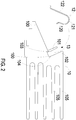
- FIG. 2 is a schematic exploded view illustrating the relationship between a heat sink and an elastic fastener of the heat dissipation assembly of FIG. 1 .
- FIG. 3 is an enlarged fragmentary view illustrating the heat sink of the heat dissipation assembly of FIG. 1 .
- the heat dissipation assembly 1 comprises a heat sink 10, an electronic component 11 and an elastic fastener 12.
- the heat sink 10 is made of a metallic material.
- the heat sink 10 comprises a contact surface 100, an engaging part 101 and a wing part 102.
- the engaging part 101 and the wing part 102 are protruded externally from the contact surface 100 of the heat sink 10. Moreover, an accommodation space 13 is defined by the engaging part 101, the wing part 102 and the contact surface 100 collaboratively.
- the engaging part 101 has a concave structure 103.
- the concave structure 103 is disposed within the accommodation space 13. Preferably but not exclusively, the concave structure 103 is located near the contact surface 100. More specifically, in this embodiment, the concave structure 103 is located adjacent to the contact surface 100.
- An example of the electronic component 11 includes but is not limited to a central processing unit, a switch element (e.g., IGBT), or a rectifier. Moreover, the electronic component 11 is disposed on the contact surface 100 of the heat sink 10. During operation of the electronic component 11, the heat generated by the electronic component 11 is dissipated away through the heat sink 10.
- a switch element e.g., IGBT
- a rectifier e.g., a rectifier
- the elastic fastener 12 comprises a first free part 120, a bent segment 121 and a second free part 122.
- the first free part 120 is accommodated within the accommodation space 13 and locked on at least one inner wall of the concave structure 103.
- the bent segment 121 is partially accommodated within the accommodation space 13 and contacted with a first sidewall 104 of the wing part 102.
- the second free part 122 is locked on an external surface 110 of the electronic component 11. Consequently, the electronic component 11 is attached and fixed on the contact surface 100 of the heat sink 10.
- a process of assembling the heat sink 10, the electronic component 11 and the elastic fastener 12 as the heat dissipation assembly 1 will be described as follows. Firstly, the electronic component 11 is placed on the contact surface 100 of the heat sink 10. Then, an external force is applied to the elastic fastener 12. In response to the external force, the first free part 120 and the bent segment 121 of the elastic fastener 12 are accommodated within the accommodation space 13, and the second free part 122 of the elastic fastener 12 is contacted with the external surface 110 of the electronic component 11. Then, in response to the external force, the first free part 120 is locked on at least one inner wall of the concave structure 103.
- the second free part 122 is locked on the external surface 110 of the electronic component 11 in response to the elastic force of the elastic fastener 12. Consequently, the electronic component 11 is attached and fixed on the contact surface 100 of the heat sink 10. Moreover, in response to the elastic force of the elastic fastener 12, the first free part 120 is locked on at least one inner wall of the concave structure 103. Consequently, the elastic fastener 12 will not detached from the accommodation space 13.
- the elastic fastener 12 can provide the elastic force.
- the electronic component 11 In response to the elastic force of the elastic fastener 12, the electronic component 11 is fixed on the heat sink 10.
- the first free part 120 is locked on at least one inner wall of the concave structure 103 and the elastic fastener 12 is fixed on the heat sink 10. Since it is not necessary to additionally uses bolts or screws to fix the electronic component 11 on the heat sink 10, the assembling process is simplified.
- the elastic fastening force is not too large or too small. Under this circumstance, the electronic component 11 is in close contact with the heat sink 10, and the possibility of causing damage of the electronic component 11 is largely reduced.
- the elastic fastener 12 since the first free part 120 of the elastic fastener 12 is engaged with the concave structure 103, the elastic fastener 12 is fixed on the heat sink 10. Moreover, the contact area between the first free part 120 and the concave structure 103 is large enough, and the joint between the first free part 120 and the concave structure 103 is not a curvy surface. Consequently, the tangential force at the joint between the first free part 120 and the concave structure 103 is small. That is, if no external force is applied to the elastic fastener 12, the first free part 120 is not easily detached from the concave structure 103. Consequently, the elastic fastener 12 can stably fixed on the heat sink 10.
- the engaging part 101 is closer to the electronic component 11 than the wing part 102. That is, the engaging part 101 is arranged between the wing part 102 and the electronic component 11.
- the length of the concave structure 103 is larger than or equal to the length of the first free part 120 of the elastic fastener 12. Consequently, the first free part 120 of the elastic fastener 12 is accommodated within the concave structure 103.
- the first sidewall 104 of the wing part 102 has a flat surface. Moreover, a first end of the bent segment 121 is connected with the first free part 120, and a second end of the bent segment 121 is connected with the second free part 122.
- the first free part 120, the bent segment 121 and the second free part 122 are integrally formed with each other.
- the first free part 120 of the elastic fastener 12 is extended in a direction away from the bent segment 121.
- the wing part 102 comprises plural fins 105.
- the plural fins 105 are protruded from a second sidewall of the wing part 102, wherein the second sidewall is opposed to the first sidewall 104.
- FIG. 4 is a schematic assembled view illustrating a heat dissipation assembly according to a second embodiment of the present invention.
- FIG. 5 is a schematic exploded view illustrating the relationship between a heat sink and an elastic fastener of the heat dissipation assembly of FIG. 4 .
- the heat sink 10 further comprises an indentation structure 106.
- the indentation structure 106 is in communication with the accommodation space 13 and concavely formed on the contact surface 100 of the heat sink 10.
- the elastic fastener 12 further comprises an extension part 123 corresponding to the indentation structure 106.
- the extension part 123 is extended from the first free part 120.
- the extension part 123 is protruded out of the concave structure 103 and inserted into the indentation structure 106. Due to the engagement between the indentation structure 106 and the extension part 123, the elastic fastener 12 is fixed on the heat sink 10 more securely.
- the engagement between the indentation structure 106 and the extension part 123 can facilitate fixing the elastic fastener 12 on the heat sink 10. Consequently, in some other embodiments, the engaging part 101 is not equipped with the concave structure 103. That is, the heat sink 10 is equipped with the indentation structure 106, and the elastic fastener 12 is equipped with the extension part 123.
- FIG. 6 is a schematic assembled view illustrating a heat dissipation assembly according to a third embodiment of the present invention.
- FIG. 7 is a schematic exploded view illustrating the relationship between a heat sink and an elastic fastener of the heat dissipation assembly of FIG. 6 .
- the first free part 120 of the elastic fastener 12 is extended in a direction away from the bent segment 121.
- the first free part 120 of the elastic fastener 12 is extended in a direction toward the bent segment 121.
- the present invention provides a heat dissipation assembly.
- the electronic component In response to the elastic force of the elastic fastener, the electronic component is fixed on the heat sink. Due to the engagement between the first free part of the elastic fastener and the concave structure, the elastic fastener is fixed on the heat sink. That is, the assembling process is simplified. Moreover, the elastic fastening force is not too large or too small. Consequently, the electronic component is securely fixed on the heat sink, and the possibility of causing damage of the electronic component is largely reduced. Moreover, since the first free part of the elastic fastener is engaged with the concave structure, the elastic fastener is fixed on the heat sink.
- the contact area between the first free part and the concave structure is large enough, and the joint between the first free part and the concave structure is not a curvy surface. Consequently, the tangential force at the joint between the first free part and the concave structure is small, and the elastic fastener can stably fixed on the heat sink.
Landscapes
- Physics & Mathematics (AREA)
- Thermal Sciences (AREA)
- Engineering & Computer Science (AREA)
- Microelectronics & Electronic Packaging (AREA)
- Cooling Or The Like Of Electrical Apparatus (AREA)
- Cooling Or The Like Of Semiconductors Or Solid State Devices (AREA)
Claims (9)
- Wärmeableitungsanordnung (1), umfassend:eine Wärmesenke (10) mit einer Kontaktfläche (100), einem Eingriffsteil (101) und einem Flügelteil (102), wobei das Eingriffsteil (101) und das Flügelteil (102) von der Kontaktfläche (100) der Wärmesenke (10) nach außen vorstehen, und ein Aufnahmeraum (13) durch das Eingriffsteil (101), das Flügelteil (102) und die Kontaktfläche (100) gemeinsam definiert ist;eine elektronische Komponente (11), die an der Kontaktfläche (100) angebracht ist, wobei das Eingriffsteil (101) zwischen dem Flügelteil (102) und der elektronischen Komponente (11) angeordnet ist; undein elastisches Befestigungselement (12) mit einem ersten freien Teil (120), einem gebogenen Segment (121) und einem zweiten freien Teil (122), wobeidas gebogene Segment (121) innerhalb des Aufnahmeraums (13) untergebracht ist und mit einer ersten Seitenwand (104) des Flügelteils (102) in Kontakt steht, undder zweite freie Teil (122) an einer Außenfläche (110) des elektronischen Bauteils (11) verriegelt ist, so dass das elektronische Bauteil (11) an der Kontaktfläche (100) des Kühlkörpers (10) angebracht und fixiert ist, wobei der erste freie Teil (120), das gebogene Segment (121) und der zweite freie Teil (122) einstückig miteinander ausgebildet sind;dadurch gekennzeichnet, dass das Eingriffsteil (101) eine konkave Struktur (103) aufweist und die konkave Struktur (103) innerhalb des Aufnahmeraums (13) angeordnet ist, undder erste freie Teil (120) innerhalb des Unterbringungsraums (13) untergebracht und an mindestens einer Innenwand der konkaven Struktur (103) verriegelt ist.
- Wärmeableitungsanordnung (1) nach Anspruch 1, wobei der Eingriffsteil (101) näher an der elektronischen Komponente (11) liegt als der Flügelteil (102).
- Wärmeableitungsanordnung (1) nach Anspruch 1 oder 2, wobei eine Länge der konkaven Struktur (103) größer oder gleich einer Länge des ersten freien Teils (120) ist.
- Wärmeableitungsanordnung (1) nach einem der vorstehenden Ansprüche, wobei eine Seitenwand des Flügelteils (102) eine ebene Oberfläche hat.
- Wärmeableitungsanordnung (1) nach einem der vorstehenden Ansprüche, wobei die Wärmesenke (10) ferner eine Einkerbungsstruktur (106) aufweist, wobei die Einkerbungsstruktur (106) mit dem Aufnahmeraum (13) in Verbindung steht und an der Kontaktfläche (100) der Wärmesenke (10) konkav ausgebildet ist.
- Wärmeableitungsanordnung (1) nach Anspruch 5, wobei der erste freie Teil (120) einen Verlängerungsteil (123) aufweist, wobei, wenn der erste freie Teil (120) mit der mindestens einen Innenwand der konkaven Struktur (103) in Kontakt gebracht wird, der Verlängerungsteil (123) aus der konkaven Struktur (103) herausragt und in die Vertiefungsstruktur (106) eingesetzt wird.
- Wärmeableitungsanordnung (1) nach Anspruch 1 oder 5, wobei sich der erste freie Teil (120) des elastischen Befestigungsmittels (12) in einer Richtung weg von dem gebogenen Segment (121) erstreckt.
- Wärmeableitungsanordnung (1) nach einem der Ansprüche 1, 5 oder 6, wobei der erste freie Teil (120) des elastischen Befestigungsmittels (12) in Richtung auf das gebogene Segment (121) verlängert ist.
- Wärmeableitungsanordnung (1) nach einem der vorstehenden Ansprüche, wobei der Flügelteil (102) mehrere Rippen (105) aufweist und die mehreren Rippen (105) aus einer zweiten Seitenwand des Flügelteils (102) hervorstehen, wobei die zweite Seitenwand der ersten Seitenwand (104) gegenüberliegt.
Applications Claiming Priority (1)
| Application Number | Priority Date | Filing Date | Title |
|---|---|---|---|
| CN201620776101.2U CN205864940U (zh) | 2016-07-22 | 2016-07-22 | 散热器组件 |
Publications (2)
| Publication Number | Publication Date |
|---|---|
| EP3273472A1 EP3273472A1 (de) | 2018-01-24 |
| EP3273472B1 true EP3273472B1 (de) | 2020-08-26 |
Family
ID=56936259
Family Applications (1)
| Application Number | Title | Priority Date | Filing Date |
|---|---|---|---|
| EP16186136.4A Active EP3273472B1 (de) | 2016-07-22 | 2016-08-29 | Wärmeableitungsanordnung |
Country Status (3)
| Country | Link |
|---|---|
| US (1) | US9955610B2 (de) |
| EP (1) | EP3273472B1 (de) |
| CN (1) | CN205864940U (de) |
Families Citing this family (1)
| Publication number | Priority date | Publication date | Assignee | Title |
|---|---|---|---|---|
| USD892753S1 (en) * | 2018-10-31 | 2020-08-11 | Bitmain Technologies Inc. | Heat sink |
Family Cites Families (6)
| Publication number | Priority date | Publication date | Assignee | Title |
|---|---|---|---|---|
| GB8531565D0 (en) * | 1985-12-21 | 1986-02-05 | Marston Palmer Ltd | Heat sink |
| SE460008B (sv) * | 1987-11-04 | 1989-08-28 | Saab Scania Ab | Kylkropp foer ett elektriskt kretskort samt anvaendning daerav |
| US5343362A (en) * | 1994-01-07 | 1994-08-30 | Zytec Corporation | Heat sink assembly |
| IT1292590B1 (it) * | 1997-05-30 | 1999-02-08 | El Bo Mec S R L | Dissipatore di calore, in particolare per componenti elettronici. |
| DE20120695U1 (de) * | 2001-12-20 | 2003-04-30 | Gebr. Jordan GmbH & Co KG, 58636 Iserlohn | Befestigungsklammer zum Befestigen eines elektrischen/elektronischen Elementes an einem Kühlkörper |
| US20080019095A1 (en) * | 2006-07-24 | 2008-01-24 | Kechuan Liu | Configurable heat sink with matrix clipping system |
-
2016
- 2016-07-22 CN CN201620776101.2U patent/CN205864940U/zh active Active
- 2016-08-29 EP EP16186136.4A patent/EP3273472B1/de active Active
- 2016-08-29 US US15/250,222 patent/US9955610B2/en active Active
Non-Patent Citations (1)
| Title |
|---|
| None * |
Also Published As
| Publication number | Publication date |
|---|---|
| US20180027699A1 (en) | 2018-01-25 |
| CN205864940U (zh) | 2017-01-04 |
| EP3273472A1 (de) | 2018-01-24 |
| US9955610B2 (en) | 2018-04-24 |
Similar Documents
| Publication | Publication Date | Title |
|---|---|---|
| US5991151A (en) | Heat sink, in particular for electronic components | |
| WO2019007081A1 (zh) | 一种处理器固定结构、组件及计算机设备 | |
| US7817427B2 (en) | Fastener and heat sink assembly having the same | |
| US8902580B2 (en) | Heat dissipation device with fastener | |
| CN101998796A (zh) | 扣具、应用该扣具的散热装置和电子装置 | |
| US9111903B2 (en) | Heat dissipation device with fastener | |
| US7661462B2 (en) | Heat dissipation assembly | |
| CN103998863A (zh) | Led模块和包括所述模块的照明设备 | |
| US20090229790A1 (en) | Radiating fin assembly for thermal module | |
| CN102111987A (zh) | 锁固结构及其制造方法、以及应用该锁固结构的散热装置 | |
| US20060260787A1 (en) | Flattened contact cooling module | |
| US20080019095A1 (en) | Configurable heat sink with matrix clipping system | |
| US20090120613A1 (en) | Heat sink | |
| US9955610B2 (en) | Heat dissipation assembly | |
| US9500417B2 (en) | Thermal module connection structure | |
| US7841388B2 (en) | Radiating fin assembly for thermal module | |
| CN101776942B (zh) | 散热器固定装置 | |
| US8944149B2 (en) | Heat dissipation device with fastener and flange | |
| US20070121300A1 (en) | Back plate assembly for mounting a heat sink assembly to a motherboard | |
| US20130153190A1 (en) | Heat sink | |
| CN112823573B (zh) | 用于PCI Express M.2印刷电路组件的热界面装置 | |
| CN103025119A (zh) | 散热装置 | |
| US9072176B2 (en) | Assembling structure of heat dissipation device | |
| US20130306294A1 (en) | Heat dissipation device with fastener | |
| TWI345697B (en) | Fastening structure and application thereof |
Legal Events
| Date | Code | Title | Description |
|---|---|---|---|
| PUAI | Public reference made under article 153(3) epc to a published international application that has entered the european phase |
Free format text: ORIGINAL CODE: 0009012 |
|
| STAA | Information on the status of an ep patent application or granted ep patent |
Free format text: STATUS: THE APPLICATION HAS BEEN PUBLISHED |
|
| AK | Designated contracting states |
Kind code of ref document: A1 Designated state(s): AL AT BE BG CH CY CZ DE DK EE ES FI FR GB GR HR HU IE IS IT LI LT LU LV MC MK MT NL NO PL PT RO RS SE SI SK SM TR |
|
| AX | Request for extension of the european patent |
Extension state: BA ME |
|
| STAA | Information on the status of an ep patent application or granted ep patent |
Free format text: STATUS: REQUEST FOR EXAMINATION WAS MADE |
|
| 17P | Request for examination filed |
Effective date: 20180717 |
|
| RBV | Designated contracting states (corrected) |
Designated state(s): AL AT BE BG CH CY CZ DE DK EE ES FI FR GB GR HR HU IE IS IT LI LT LU LV MC MK MT NL NO PL PT RO RS SE SI SK SM TR |
|
| STAA | Information on the status of an ep patent application or granted ep patent |
Free format text: STATUS: EXAMINATION IS IN PROGRESS |
|
| 17Q | First examination report despatched |
Effective date: 20181025 |
|
| GRAP | Despatch of communication of intention to grant a patent |
Free format text: ORIGINAL CODE: EPIDOSNIGR1 |
|
| STAA | Information on the status of an ep patent application or granted ep patent |
Free format text: STATUS: GRANT OF PATENT IS INTENDED |
|
| INTG | Intention to grant announced |
Effective date: 20200320 |
|
| GRAS | Grant fee paid |
Free format text: ORIGINAL CODE: EPIDOSNIGR3 |
|
| GRAA | (expected) grant |
Free format text: ORIGINAL CODE: 0009210 |
|
| STAA | Information on the status of an ep patent application or granted ep patent |
Free format text: STATUS: THE PATENT HAS BEEN GRANTED |
|
| AK | Designated contracting states |
Kind code of ref document: B1 Designated state(s): AL AT BE BG CH CY CZ DE DK EE ES FI FR GB GR HR HU IE IS IT LI LT LU LV MC MK MT NL NO PL PT RO RS SE SI SK SM TR |
|
| REG | Reference to a national code |
Ref country code: GB Ref legal event code: FG4D |
|
| REG | Reference to a national code |
Ref country code: CH Ref legal event code: EP |
|
| REG | Reference to a national code |
Ref country code: AT Ref legal event code: REF Ref document number: 1307203 Country of ref document: AT Kind code of ref document: T Effective date: 20200915 |
|
| REG | Reference to a national code |
Ref country code: IE Ref legal event code: FG4D |
|
| REG | Reference to a national code |
Ref country code: DE Ref legal event code: R096 Ref document number: 602016042635 Country of ref document: DE |
|
| REG | Reference to a national code |
Ref country code: LT Ref legal event code: MG4D |
|
| PG25 | Lapsed in a contracting state [announced via postgrant information from national office to epo] |
Ref country code: FI Free format text: LAPSE BECAUSE OF FAILURE TO SUBMIT A TRANSLATION OF THE DESCRIPTION OR TO PAY THE FEE WITHIN THE PRESCRIBED TIME-LIMIT Effective date: 20200826 Ref country code: PT Free format text: LAPSE BECAUSE OF FAILURE TO SUBMIT A TRANSLATION OF THE DESCRIPTION OR TO PAY THE FEE WITHIN THE PRESCRIBED TIME-LIMIT Effective date: 20201228 Ref country code: HR Free format text: LAPSE BECAUSE OF FAILURE TO SUBMIT A TRANSLATION OF THE DESCRIPTION OR TO PAY THE FEE WITHIN THE PRESCRIBED TIME-LIMIT Effective date: 20200826 Ref country code: SE Free format text: LAPSE BECAUSE OF FAILURE TO SUBMIT A TRANSLATION OF THE DESCRIPTION OR TO PAY THE FEE WITHIN THE PRESCRIBED TIME-LIMIT Effective date: 20200826 Ref country code: BG Free format text: LAPSE BECAUSE OF FAILURE TO SUBMIT A TRANSLATION OF THE DESCRIPTION OR TO PAY THE FEE WITHIN THE PRESCRIBED TIME-LIMIT Effective date: 20201126 Ref country code: NO Free format text: LAPSE BECAUSE OF FAILURE TO SUBMIT A TRANSLATION OF THE DESCRIPTION OR TO PAY THE FEE WITHIN THE PRESCRIBED TIME-LIMIT Effective date: 20201126 Ref country code: GR Free format text: LAPSE BECAUSE OF FAILURE TO SUBMIT A TRANSLATION OF THE DESCRIPTION OR TO PAY THE FEE WITHIN THE PRESCRIBED TIME-LIMIT Effective date: 20201127 Ref country code: LT Free format text: LAPSE BECAUSE OF FAILURE TO SUBMIT A TRANSLATION OF THE DESCRIPTION OR TO PAY THE FEE WITHIN THE PRESCRIBED TIME-LIMIT Effective date: 20200826 |
|
| REG | Reference to a national code |
Ref country code: NL Ref legal event code: MP Effective date: 20200826 |
|
| REG | Reference to a national code |
Ref country code: AT Ref legal event code: MK05 Ref document number: 1307203 Country of ref document: AT Kind code of ref document: T Effective date: 20200826 |
|
| PG25 | Lapsed in a contracting state [announced via postgrant information from national office to epo] |
Ref country code: NL Free format text: LAPSE BECAUSE OF FAILURE TO SUBMIT A TRANSLATION OF THE DESCRIPTION OR TO PAY THE FEE WITHIN THE PRESCRIBED TIME-LIMIT Effective date: 20200826 Ref country code: RS Free format text: LAPSE BECAUSE OF FAILURE TO SUBMIT A TRANSLATION OF THE DESCRIPTION OR TO PAY THE FEE WITHIN THE PRESCRIBED TIME-LIMIT Effective date: 20200826 Ref country code: PL Free format text: LAPSE BECAUSE OF FAILURE TO SUBMIT A TRANSLATION OF THE DESCRIPTION OR TO PAY THE FEE WITHIN THE PRESCRIBED TIME-LIMIT Effective date: 20200826 Ref country code: LV Free format text: LAPSE BECAUSE OF FAILURE TO SUBMIT A TRANSLATION OF THE DESCRIPTION OR TO PAY THE FEE WITHIN THE PRESCRIBED TIME-LIMIT Effective date: 20200826 Ref country code: IS Free format text: LAPSE BECAUSE OF FAILURE TO SUBMIT A TRANSLATION OF THE DESCRIPTION OR TO PAY THE FEE WITHIN THE PRESCRIBED TIME-LIMIT Effective date: 20201226 |
|
| REG | Reference to a national code |
Ref country code: CH Ref legal event code: PL |
|
| PG25 | Lapsed in a contracting state [announced via postgrant information from national office to epo] |
Ref country code: DK Free format text: LAPSE BECAUSE OF FAILURE TO SUBMIT A TRANSLATION OF THE DESCRIPTION OR TO PAY THE FEE WITHIN THE PRESCRIBED TIME-LIMIT Effective date: 20200826 Ref country code: CH Free format text: LAPSE BECAUSE OF NON-PAYMENT OF DUE FEES Effective date: 20200831 Ref country code: CZ Free format text: LAPSE BECAUSE OF FAILURE TO SUBMIT A TRANSLATION OF THE DESCRIPTION OR TO PAY THE FEE WITHIN THE PRESCRIBED TIME-LIMIT Effective date: 20200826 Ref country code: RO Free format text: LAPSE BECAUSE OF FAILURE TO SUBMIT A TRANSLATION OF THE DESCRIPTION OR TO PAY THE FEE WITHIN THE PRESCRIBED TIME-LIMIT Effective date: 20200826 Ref country code: SM Free format text: LAPSE BECAUSE OF FAILURE TO SUBMIT A TRANSLATION OF THE DESCRIPTION OR TO PAY THE FEE WITHIN THE PRESCRIBED TIME-LIMIT Effective date: 20200826 Ref country code: LI Free format text: LAPSE BECAUSE OF NON-PAYMENT OF DUE FEES Effective date: 20200831 Ref country code: LU Free format text: LAPSE BECAUSE OF NON-PAYMENT OF DUE FEES Effective date: 20200829 Ref country code: EE Free format text: LAPSE BECAUSE OF FAILURE TO SUBMIT A TRANSLATION OF THE DESCRIPTION OR TO PAY THE FEE WITHIN THE PRESCRIBED TIME-LIMIT Effective date: 20200826 |
|
| REG | Reference to a national code |
Ref country code: BE Ref legal event code: MM Effective date: 20200831 |
|
| REG | Reference to a national code |
Ref country code: DE Ref legal event code: R097 Ref document number: 602016042635 Country of ref document: DE |
|
| PG25 | Lapsed in a contracting state [announced via postgrant information from national office to epo] |
Ref country code: ES Free format text: LAPSE BECAUSE OF FAILURE TO SUBMIT A TRANSLATION OF THE DESCRIPTION OR TO PAY THE FEE WITHIN THE PRESCRIBED TIME-LIMIT Effective date: 20200826 Ref country code: AL Free format text: LAPSE BECAUSE OF FAILURE TO SUBMIT A TRANSLATION OF THE DESCRIPTION OR TO PAY THE FEE WITHIN THE PRESCRIBED TIME-LIMIT Effective date: 20200826 Ref country code: AT Free format text: LAPSE BECAUSE OF FAILURE TO SUBMIT A TRANSLATION OF THE DESCRIPTION OR TO PAY THE FEE WITHIN THE PRESCRIBED TIME-LIMIT Effective date: 20200826 Ref country code: MC Free format text: LAPSE BECAUSE OF FAILURE TO SUBMIT A TRANSLATION OF THE DESCRIPTION OR TO PAY THE FEE WITHIN THE PRESCRIBED TIME-LIMIT Effective date: 20200826 |
|
| PG25 | Lapsed in a contracting state [announced via postgrant information from national office to epo] |
Ref country code: SK Free format text: LAPSE BECAUSE OF FAILURE TO SUBMIT A TRANSLATION OF THE DESCRIPTION OR TO PAY THE FEE WITHIN THE PRESCRIBED TIME-LIMIT Effective date: 20200826 |
|
| PLBE | No opposition filed within time limit |
Free format text: ORIGINAL CODE: 0009261 |
|
| STAA | Information on the status of an ep patent application or granted ep patent |
Free format text: STATUS: NO OPPOSITION FILED WITHIN TIME LIMIT |
|
| GBPC | Gb: european patent ceased through non-payment of renewal fee |
Effective date: 20201126 |
|
| PG25 | Lapsed in a contracting state [announced via postgrant information from national office to epo] |
Ref country code: IT Free format text: LAPSE BECAUSE OF FAILURE TO SUBMIT A TRANSLATION OF THE DESCRIPTION OR TO PAY THE FEE WITHIN THE PRESCRIBED TIME-LIMIT Effective date: 20200826 |
|
| 26N | No opposition filed |
Effective date: 20210527 |
|
| PG25 | Lapsed in a contracting state [announced via postgrant information from national office to epo] |
Ref country code: BE Free format text: LAPSE BECAUSE OF NON-PAYMENT OF DUE FEES Effective date: 20200831 Ref country code: SI Free format text: LAPSE BECAUSE OF FAILURE TO SUBMIT A TRANSLATION OF THE DESCRIPTION OR TO PAY THE FEE WITHIN THE PRESCRIBED TIME-LIMIT Effective date: 20200826 Ref country code: IE Free format text: LAPSE BECAUSE OF NON-PAYMENT OF DUE FEES Effective date: 20200829 |
|
| PG25 | Lapsed in a contracting state [announced via postgrant information from national office to epo] |
Ref country code: GB Free format text: LAPSE BECAUSE OF NON-PAYMENT OF DUE FEES Effective date: 20201126 |
|
| PG25 | Lapsed in a contracting state [announced via postgrant information from national office to epo] |
Ref country code: IS Free format text: LAPSE BECAUSE OF FAILURE TO SUBMIT A TRANSLATION OF THE DESCRIPTION OR TO PAY THE FEE WITHIN THE PRESCRIBED TIME-LIMIT Effective date: 20201226 Ref country code: MT Free format text: LAPSE BECAUSE OF FAILURE TO SUBMIT A TRANSLATION OF THE DESCRIPTION OR TO PAY THE FEE WITHIN THE PRESCRIBED TIME-LIMIT Effective date: 20200826 Ref country code: CY Free format text: LAPSE BECAUSE OF FAILURE TO SUBMIT A TRANSLATION OF THE DESCRIPTION OR TO PAY THE FEE WITHIN THE PRESCRIBED TIME-LIMIT Effective date: 20200826 |
|
| PG25 | Lapsed in a contracting state [announced via postgrant information from national office to epo] |
Ref country code: MK Free format text: LAPSE BECAUSE OF FAILURE TO SUBMIT A TRANSLATION OF THE DESCRIPTION OR TO PAY THE FEE WITHIN THE PRESCRIBED TIME-LIMIT Effective date: 20200826 |
|
| PGFP | Annual fee paid to national office [announced via postgrant information from national office to epo] |
Ref country code: DE Payment date: 20250702 Year of fee payment: 10 |
|
| PGFP | Annual fee paid to national office [announced via postgrant information from national office to epo] |
Ref country code: TR Payment date: 20250828 Year of fee payment: 10 |
|
| PGFP | Annual fee paid to national office [announced via postgrant information from national office to epo] |
Ref country code: FR Payment date: 20250703 Year of fee payment: 10 |
|
| REG | Reference to a national code |
Ref country code: DE Ref legal event code: R079 Ref document number: 602016042635 Country of ref document: DE Free format text: PREVIOUS MAIN CLASS: H01L0023400000 Ipc: H10W0040600000 |