EP3273091A1 - Method and product for conical spring having variable stiffness and capable of preventing folding and cracking - Google Patents
Method and product for conical spring having variable stiffness and capable of preventing folding and cracking Download PDFInfo
- Publication number
- EP3273091A1 EP3273091A1 EP15885051.1A EP15885051A EP3273091A1 EP 3273091 A1 EP3273091 A1 EP 3273091A1 EP 15885051 A EP15885051 A EP 15885051A EP 3273091 A1 EP3273091 A1 EP 3273091A1
- Authority
- EP
- European Patent Office
- Prior art keywords
- rubber
- section
- conical
- rubber body
- stiffness
- Prior art date
- Legal status (The legal status is an assumption and is not a legal conclusion. Google has not performed a legal analysis and makes no representation as to the accuracy of the status listed.)
- Granted
Links
Images


Classifications
-
- F—MECHANICAL ENGINEERING; LIGHTING; HEATING; WEAPONS; BLASTING
- F16—ENGINEERING ELEMENTS AND UNITS; GENERAL MEASURES FOR PRODUCING AND MAINTAINING EFFECTIVE FUNCTIONING OF MACHINES OR INSTALLATIONS; THERMAL INSULATION IN GENERAL
- F16F—SPRINGS; SHOCK-ABSORBERS; MEANS FOR DAMPING VIBRATION
- F16F1/00—Springs
- F16F1/36—Springs made of rubber or other material having high internal friction, e.g. thermoplastic elastomers
- F16F1/38—Springs made of rubber or other material having high internal friction, e.g. thermoplastic elastomers with a sleeve of elastic material between a rigid outer sleeve and a rigid inner sleeve or pin, i.e. bushing-type
- F16F1/393—Springs made of rubber or other material having high internal friction, e.g. thermoplastic elastomers with a sleeve of elastic material between a rigid outer sleeve and a rigid inner sleeve or pin, i.e. bushing-type with spherical or conical sleeves
- F16F1/3935—Conical sleeves
-
- F—MECHANICAL ENGINEERING; LIGHTING; HEATING; WEAPONS; BLASTING
- F16—ENGINEERING ELEMENTS AND UNITS; GENERAL MEASURES FOR PRODUCING AND MAINTAINING EFFECTIVE FUNCTIONING OF MACHINES OR INSTALLATIONS; THERMAL INSULATION IN GENERAL
- F16F—SPRINGS; SHOCK-ABSORBERS; MEANS FOR DAMPING VIBRATION
- F16F1/00—Springs
- F16F1/36—Springs made of rubber or other material having high internal friction, e.g. thermoplastic elastomers
- F16F1/38—Springs made of rubber or other material having high internal friction, e.g. thermoplastic elastomers with a sleeve of elastic material between a rigid outer sleeve and a rigid inner sleeve or pin, i.e. bushing-type
- F16F1/3828—End stop features or buffering
-
- F—MECHANICAL ENGINEERING; LIGHTING; HEATING; WEAPONS; BLASTING
- F16—ENGINEERING ELEMENTS AND UNITS; GENERAL MEASURES FOR PRODUCING AND MAINTAINING EFFECTIVE FUNCTIONING OF MACHINES OR INSTALLATIONS; THERMAL INSULATION IN GENERAL
- F16F—SPRINGS; SHOCK-ABSORBERS; MEANS FOR DAMPING VIBRATION
- F16F1/00—Springs
- F16F1/36—Springs made of rubber or other material having high internal friction, e.g. thermoplastic elastomers
- F16F1/38—Springs made of rubber or other material having high internal friction, e.g. thermoplastic elastomers with a sleeve of elastic material between a rigid outer sleeve and a rigid inner sleeve or pin, i.e. bushing-type
- F16F1/3863—Springs made of rubber or other material having high internal friction, e.g. thermoplastic elastomers with a sleeve of elastic material between a rigid outer sleeve and a rigid inner sleeve or pin, i.e. bushing-type characterised by the rigid sleeves or pin, e.g. of non-circular cross-section
Definitions
- the invention relates to improvement of a conical spring used on a locomotive, especially a method for adjusting stiffness changes of a conical spring and a conical spring structure.
- the method and the conical spring structure may implement multiple stiffness changes of the conical spring and prevent rubber of the conical spring from folding and cracking due to compression while in use.
- the invention belongs to the technical field of elastic shock absorption.
- a conical spring also called journal box spring, mainly refers to a spring with a shock absorption effect formed by combining metal with rubber on a locomotive.
- the conical spring is installed between a journal box and a frame of a rail locomotive to achieve the effects of support, shock absorption and noise reduction, is a frequently-used shock-absorption and noise-reduction element formed by combining rubber with metal, is installed on a locomotive body of single-stage suspension and two-stage suspension of the locomotive, and is mainly used for bearing the load of the locomotive body and the frame.
- the conical spring Formed by vulcanizing a conical metal piece and rubber into a whole through an adhesive at certain temperature and pressure, the conical spring achieves the effects of shock absorption and noise reduction using the vulcanized rubber, and achieves the effects of support and installation interface using the metal piece.
- the conical spring in order to preferably meet and guarantee the dynamics requirements and safety of locomotives, it is required that the conical spring should have changeable stiffness in vertical stiffness, and the phenomenon of an inverse S curve should not occur to the vertical stiffness.
- the inverse S curve occurs to the vertical stiffness is because that a rubber body of the existing conical spring structure has no strong mutual extrusion and has no extrusion of contact between an externally protruded lug boss and rubber, the vertical changeable stiffness of the conical spring is too small under no load, when the locomotive is under load, especially under the maximum vertical load, when it is required that the rubber part of the conical spring should provide sufficiently large vertical stiffness, but the existing conical spring cannot provide large changeable stiffness, so that ideal changeable stiffness cannot be achieved, and thus the stiffness curve presents inverse "S".
- the conical spring having an inverse "S" curve has large stiffness under no load, so that the risk of derail of the locomotive may be caused.
- the conical spring has appropriate transverse changeable stiffness and longitudinal changeable stiffness, so that the locomotive more meets dynamics requirements, thereby having good effects of transverse and longitudinal shock absorption and noise reduction. Therefore, by appropriately increasing the number of transverse changeable stiffness and longitudinal changeable stiffness of the locomotive to achieve multiple changes of stiffness, the locomotive may be made to run more steady and smooth. Because the conical spring is a whole formed by vulcanizing metal and rubber, which cannot be disassembled and cannot be conveniently repaired locally, the conical spring is a lifelong maintenance-free product. With the development of technique of locomotives, the fatigue load thereof becomes harsh more and more, and the requirement for fatigue performance becomes strict more and more.
- the utility model discloses a journal box spring for a bogie of an overloaded railway wagon.
- the object of the utility model is to provide a journal box spring for a bogie of an overloaded railway wagon, to overcome the defects of over large radial stiffness, heavy weight and the like of the existing journal box spring.
- the utility model comprises an outer sleeve, an inner sleeve, an inner core, a first rubber layer and a second rubber layer, and is characterized in that the first rubber layer and the second rubber layer are vulcanized into a whole together with the outer sleeve, the inner sleeve and the inner core, the outer sleeve is connected to the inner core through a copper conducting wire built in the surface of the first rubber layer and the second rubber layer, and the included angle between the side extension of the first rubber layer and the second rubber layer and the top of the plane journal box spring is 100-160°.
- the utility model mainly relates to a journal box spring used on a bogie of an overloaded railway wagon.
- the patent for utility models does not make the journal box spring implement multiple changeable stiffness structure, so that it is difficult to meet multiple changes of stiffness required by a locomotive in different states.
- the conical spring comprises an inner conical body, a rubber body and an outer conical body.
- the rubber body encircles the periphery of the inner conical body.
- the outer conical body encircles the periphery of the rubber body.
- the rubber body, the inner conical body and the outer conical body form a conical rubber metal spring together.
- the method of the invention has the characteristic that an upper rubber profile of the rubber body and a lower rubber profile of the rubber body of the conical spring adopt a multi-segment structural form, wherein the upper rubber profile of the rubber body is of a multi-section downslope structure, and the lower rubber profile of the rubber body is of a multi-section upslope structure; for the conical spring, the size of stiffness change and the position of stiffness change of the conical spring are adjusted by adjusting the shape, slope and length of each section in the multi-section downslope structure of the upper rubber profile of the rubber body and the multi-section upslope structure of the lower rubber profile of the rubber body, and the adjustment of multiple stiffness changes is achieved by controlling the number of multiple sections.
- the shape of each section is a straight line or arc shape, and every two sections are connected through arc section transition, to guarantee that in the process of downwards moving the upper end of the rubber body, the shape of the upper end of the rubber body is always kept as a smooth shape, so that no fold and crack may be generated.
- the shape of each section is a straight line or arc shape, every two sections are connected through arc section transition, to guarantee that in the process of downwards moving the rubber body, the shape of the lower end surface of the rubber body is always kept as a smooth shape, so that no fold and crack may be generated.
- a lug boss is externally protruded from the bottom of the inner conical body, and after the rubber body downwards moves to the lower end surface of the rubber body and comes into contact with the lug boss, substantial changeable stiffness is generated by the cooperation of double restriction of the lug boss externally protruded from the bottom of the inner conical body and the inner side of the outer conical body; under the action of vertical load, the lower end surface of the rubber body is simultaneously closely fitted with the inner side of the outer conical body and the externally protruded lug boss of the lower part of the inner conical body gradually in a rolling mode, to achieve substantial changeable stiffness.
- the upper surface of the lug boss is of a multi-section structure, every two sections adopt an arc section for transition, the size of stiffness change and the position of stiffness change are adjusted by adjusting the shape, slope and length of each section of the lug boss and the opening angle of the inner side of the outer conical body, and the adjustment of multiple stiffness changes is achieved by controlling the number of multiple sections.
- a conical spring for carrying out the above method for changing stiffness and preventing folding and cracking of the conical spring which comprises an inner conical body, a rubber body and an outer conical body.
- the rubber body encircles the periphery of the inner conical body.
- the outer conical body encircles the periphery of the rubber body.
- the rubber body, the inner conical body and the outer conical body form a conical rubber metal spring together;
- the method of the invention has the characteristic that an upper rubber profile of the rubber body of the conical spring and a lower rubber profile of the rubber body adopt a multi-section structure form, wherein the upper rubber profile of the rubber body is of a multi-section downslope structure form, and the lower rubber profile of the rubber body is of a multi-section upslope structure.
- the shape of each section is a straight line or arc shape, every two sections adopt an arc section for transition, to guarantee that in the process of downwards moving the upper end of the rubber body, the shape of the upper end of the rubber body is always kept as a smooth shape, so that no fold and crack may be generated.
- the shape of each section is a straight line or arc shape, every two sections adopt an arc section for transition, to guarantee that in the process of downwards moving the rubber body, the shape of the lower end surface of the rubber body is always kept as a smooth shape, so that no fold and crack may be generated.
- a lug boss is externally protruded from the bottom of the inner conical body, after the rubber body downwards moves to the lower end surface of the rubber body and comes into contact with the lug boss, substantial changeable stiffness is generated by the cooperation of double restriction of the lug boss externally protruded from the bottom of the inner conical body and the inner side of the outer conical body; under the action of vertical load, the lower end surface of the rubber body is simultaneously closely fitted with the inner side of the outer conical body and the externally protruded lug boss of the lower part of the inner conical body gradually in a rolling mode, to achieve substantial changeable stiffness.
- the upper surface of the lug boss is of a multi-section structure, every two sections adopt an arc section for transition, and the size of stiffness change and the position of stiffness change are adjusted by adjusting the shape, slope and length of each section of the lug boss and the opening angle of the inner side of the outer conical body; and the adjustment of multiple stiffness changes is achieved by controlling the number of multiple sections.
- inner conical body 11. inner conical body lug boss; 111. lug boss transition edge; 2. rubber body; 21. annular straight section; 211. first annular straight section; 212. second annular straight section; 213. third annular straight section; 214. fourth annular straight section; 215. fifth annular straight section; 22. annular fillet section; 3. outer conical body.
- a conical spring comprising an inner conical body 1, a rubber body 2 and an outer conical body 3, wherein the lower end of the inner conical body 1 extends to the outer side to form an annular inner conical body lug boss 11.
- the upper end surface of the rubber body 2 is of a multi-section downslope structure of three sections which are a first annular straight section 211, a second annular straight section 212 and a third annular straight section 213 respectively, and every two annular straight sections adopt the annular fillet section 22 for transition.
- the so-called multi-section downslope structure is a gradually descending trend of the rubber body 2 from the joint with the outer conical body 3 to the inner conical body 1 of the rubber body 2.
- the lower end surface of the rubber body 2 is of a multi-section upslope structure of two sections which are a fourth annular straight section 214 and a fifth annular straight section 215 respectively, and the fourth annular straight section 214 and the fifth annular straight section 215 also adopt the annular fillet section 22 for transition.
- the so-called multi-section upslope structure is a gradually ascending trend of the rubber body 2 from the joint with the inner conical body 1 to the outer conical body 3 of the rubber body 2.
- the fillet radius of the annular fillet section 22 of the lower end surface of the rubber body 2 is 15-25 mm, and fillet radii of the two annular fillet sections 22 of the upper end of the rubber body 2 are both 4-8 mm.
- the rubber body 2 encircles the periphery of the inner conical body 1, and the outer conical body 3 encircles the periphery of the rubber body 2.
- the inner conical body 1 and the outer conical body 3 are metal components, the inner conical body 1 and the outer conical body 3, and the rubber body 2 are vulcanized into a whole through an adhesive at certain temperature and pressure. The effects thereof are: the rubber body achieves the effects of shock absorption and noise reduction, and the inner conical body 1 and the outer conical body 3 achieve the effects of support and installation interface.
- both the upper end and the lower end of the rubber body 2 adopt a shape of combining a straight section with an arc section.
- corresponding folds at E and F in Figure 11 may occur to the upper end surface and the lower end surface of the rubber body 2, which will cause cracks of the rubber body 2 over time; because the conical spring is a whole formed by vulcanizing metal and rubber, which cannot be disassembled and cannot be conveniently repaired locally, the conical spring is a lifelong maintenance-free product, so that the conical spring is replaced if the rubber body 2 cracks.
- the structure used in this embodiment is as shown in Figure 1 and Figure 2 .
- the upper end of the rubber body 2 is formed into a whole by the first annular straight section 211, the second annular straight section 212, the third annular straight section 213 and two annular fillet sections 22.
- the first annular straight section 211 and the second annular straight section 212 adopt the annular fillet sections 22 for transition, and the second annular straight section 212 and the third annular straight section 213 also adopt the annular fillet sections 22 for transition.
- the change of the shape of the upper end of the rubber body 2 may be affected by multiple factors such as the slope and length of each annular straight section 21, inside slope of the outer conical body 3 and the like.
- any one of the first annular straight section 211 and the second annular straight section is inwards tilted rather than outwards tilted as in Figure 1 .
- the shape of the upper end of the rubber body 2 may present a fold similar to that at E in Figure 11 in the process of downwards moving the rubber body 2.
- the Table shows the included angle between each annular straight section of the rubber body 2 in this embodiment and the vertical direction and the length of each annular straight section.
- annular straight section 14-17 (a in Figure 1 ) 18-22 Second annular straight section 44-47(b in Figure 1 ) 20-23 Third annular straight section 14-16 (c in Figure 1 ) 11-15 Fourth annular straight section 9-11 (d in Figure 1 ) 49-52 Fifth annular straight section 86-88 (e in Figure 1 ) 5-8
- the lower end of the inner conical body 1 extends to the outer side to form an annular inner conical body lug boss 11
- the lower end of the rubber body 2 is located above the inner conical body lug boss 11
- a fourth annular straight section 214 and a fifth annular straight section 215 are provided at the lower end of the rubber body 2, and the fourth annular straight section 214 and the fifth annular straight section 215 adopt the annular fillet section 22 for transition.
- the lower end of the rubber body 2 When the conical spring is subjected to the downward pressure of the vertical load, the lower end of the rubber body 2 downwards moves and changes in shape, but the change in shape of the lower end of the rubber body 2 is restricted by both the inner side of the outer conical body 3 and the inner conical body lug boss 11. Therefore, the lower end of the rubber body 2 may be fitted with the inner conical body lug boss 11 and the inner side of the outer conical body 3, the inner conical body lug boss 11 and the lug boss transition edge 111 adopt a gentle straight line edge for transition, so that a smooth shape may be formed when the lower end of the rubber body 2 is fitted with the inner conical body lug boss 11 and the inner side of the outer conical body 3.
- the lower end of the rubber body 2 may be prevented from folding, so that the lower end of the rubber body 2 may be prevented from cracking.
- the shape of the lower end of the rubber body 2 may present a smooth shape as shown at D in Figure 6 , also see that shown in Figure 8 .
- the positions of vertical changeable stiffness, transverse changeable stiffness and longitudinal changeable stiffness of the conical spring may be adjusted by changing the length of the annular straight section 21; the number of times of changing vertical stiffness, transverse stiffness and longitudinal stiffness may be increased by increasing the number of the annular straight sections 21; and the vertical changeable stiffness, transverse changeable stiffness and longitudinal changeable stiffness of the conical spring may be adjusted by changing the slope of the annular straight section 21.
- the conical spring should not have too large stiffness but should have good elasticity, so that good elasticity refers that a good effect of shock absorption may be achieved since the stiffness of conical spring may be not suddenly increased even if the pressure of the load of the locomotive on the conical spring is suddenly increased.
- the conical spring should have large stiffness and should have good elasticity, which requires that the conical spring should have good changeable stiffness to meet the stiffness requirements of the locomotive in various cases.
- each conical spring is subjected to a vertical load of about 14KN-18KN, it can be seen from Figure 12 that 14KN-18KN is at the inverse S curve of the vertical stiffness of the conical spring.
- the inverse S curve has the characteristic that the distance of downward movement of the rubber body 2 is not large, but the stiffness thereof is increased quickly, and such stiffness increase mode is not beneficial to the shock absorption of the locomotive, which may cause the risk of derail of the locomotive.
- the changeable stiffness of the conical spring may be changed by changing the length or slope of any one of the five annular straight sections 21 during manufacture, that is to say, the changeable stiffness of the conical spring may be changed by adjusting the length or slope of the annular straight section.
- the conical spring When the vertical load is not large, for the conical spring, because of the above-mentioned three stiffness changes, the conical spring may have good effects of buffering and shock absorption; when the vertical load is large and even reaches the maximum vertical load, as shown in Figure 6 , both the upper end of the rubber body 2 of the conical spring and the lower end of the rubber body 2 are in a smooth shape without stiffness change. Therefore, it can be seen from Figure 9 that the stiffness change thereof is not as gentle as that under small load. However, because under the maximum vertical load, the conical spring can still bear load using the rubber body 2, the conical spring can still have good effects of buffering, shock absorption and noise reduction at this moment.
- the design of the five annular straight sections 21 and three annular fillet sections 22 in this embodiment enables the shapes of both the upper end and the lower end of the rubber body 2 to have no fold in the process that the conical spring bears no load to bears the maximum vertical load, thereby preventing the rubber body 2 from cracking.
- the upper end surface of the upper rubber body 2 and the lower end surface of the rubber body 2, and the lug boss transition edge 111 adopt gentle curve edge for transition rather than non-gentle straight line edge for transition.
- the upper end of the rubber body 2 is divided into four annular straight sections 21 and three annular fillet sections 22, while the lower end of the rubber body 2 is divided into three annular straight sections 21 and two annular fillet sections 22.
- the number of times of stiffness changes of the conical spring may be changed by changing the number of annular straight sections 21, that is to say, the number of times of stiffness changes of the conical spring may be changed by adjusting the number of annular straight sections 21.
- the conical spring comprises an inner conical body, a rubber body and an outer conical body.
- the rubber body encircles the periphery of the inner conical body.
- the outer conical body encircles the periphery of the rubber body.
- the rubber body, the inner conical body and the outer conical body form a conical rubber metal spring together.
- the method of the invention has the characteristic that an upper rubber profile of the rubber body and a lower rubber profile of the rubber body of the conical spring adopt a multi-segment structural form, wherein the upper rubber profile of the rubber body is of a multi-section downslope structure, and the lower rubber profile of the rubber body is of a multi-section upslope structure; for the conical spring, the size of stiffness change and the position of stiffness change of the conical spring are adjusted by adjusting the shape, slope and length of each section in the multi-section downslope structure of the upper rubber profile of the rubber body and the multi-section upslope structure of the lower rubber profile of the rubber body, and the adjustment of multiple stiffness changes is achieved by controlling the number of multiple sections.
- the shape of each section is a straight line or arc shape, every two sections are connected through an arc section transition, to guarantee that in the process of downwards moving the upper end of the rubber body, the shape of the upper end of the rubber body is always kept as a smooth shape, so that no fold and crack may be generated.
- the shape of each section is a straight line or arc shape, every two sections are connected through arc section transition, to guarantee that in the process of downwards moving the rubber body, the shape of the lower end surface of the rubber body is always kept as a smooth shape, so that no fold and crack may be generated.
- a lug boss is externally protruded from the bottom of the inner conical body, and after the rubber body downwards moves to the lower end surface of the rubber body and comes into contact with the lug boss, substantial changeable stiffness is generated by the cooperation of double restriction of the lug boss externally protruded from the bottom of the inner conical body and the inner side of the outer conical body; under the action of vertical load, the lower end surface of the rubber body is simultaneously closely fitted with the inner side of the outer conical body and the externally protruded lug boss of the lower part of the inner conical body gradually in a rolling mode, to achieve substantial changeable stiffness.
- the upper surface of the lug boss is of a multi-section structure, every two sections adopt an arc section for transition, the size of stiffness change and the position of stiffness change are adjusted by adjusting the shape, slope and length of each section of the lug boss and the opening angle of the inner side of the outer conical body, and the adjustment multiple of stiffness changes is achieved by controlling the number of multiple sections.
Landscapes
- Engineering & Computer Science (AREA)
- General Engineering & Computer Science (AREA)
- Mechanical Engineering (AREA)
- Springs (AREA)
Abstract
Description
- The invention relates to improvement of a conical spring used on a locomotive, especially a method for adjusting stiffness changes of a conical spring and a conical spring structure. The method and the conical spring structure may implement multiple stiffness changes of the conical spring and prevent rubber of the conical spring from folding and cracking due to compression while in use. The invention belongs to the technical field of elastic shock absorption.
- A conical spring, also called journal box spring, mainly refers to a spring with a shock absorption effect formed by combining metal with rubber on a locomotive. The conical spring is installed between a journal box and a frame of a rail locomotive to achieve the effects of support, shock absorption and noise reduction, is a frequently-used shock-absorption and noise-reduction element formed by combining rubber with metal, is installed on a locomotive body of single-stage suspension and two-stage suspension of the locomotive, and is mainly used for bearing the load of the locomotive body and the frame. Formed by vulcanizing a conical metal piece and rubber into a whole through an adhesive at certain temperature and pressure, the conical spring achieves the effects of shock absorption and noise reduction using the vulcanized rubber, and achieves the effects of support and installation interface using the metal piece.
- With the development of technique of locomotives, especially the development of technique of high-speed railway motor train units, urban rail trains, metro vehicles and low-floor vehicles, for the conical spring, in order to preferably meet and guarantee the dynamics requirements and safety of locomotives, it is required that the conical spring should have changeable stiffness in vertical stiffness, and the phenomenon of an inverse S curve should not occur to the vertical stiffness. The fact that the inverse S curve occurs to the vertical stiffness is because that a rubber body of the existing conical spring structure has no strong mutual extrusion and has no extrusion of contact between an externally protruded lug boss and rubber, the vertical changeable stiffness of the conical spring is too small under no load, when the locomotive is under load, especially under the maximum vertical load, when it is required that the rubber part of the conical spring should provide sufficiently large vertical stiffness, but the existing conical spring cannot provide large changeable stiffness, so that ideal changeable stiffness cannot be achieved, and thus the stiffness curve presents inverse "S". The conical spring having an inverse "S" curve has large stiffness under no load, so that the risk of derail of the locomotive may be caused. In addition, when the locomotive accelerates, decelerates or makes a turn, it is required that the conical spring has appropriate transverse changeable stiffness and longitudinal changeable stiffness, so that the locomotive more meets dynamics requirements, thereby having good effects of transverse and longitudinal shock absorption and noise reduction. Therefore, by appropriately increasing the number of transverse changeable stiffness and longitudinal changeable stiffness of the locomotive to achieve multiple changes of stiffness, the locomotive may be made to run more steady and smooth. Because the conical spring is a whole formed by vulcanizing metal and rubber, which cannot be disassembled and cannot be conveniently repaired locally, the conical spring is a lifelong maintenance-free product. With the development of technique of locomotives, the fatigue load thereof becomes harsh more and more, and the requirement for fatigue performance becomes strict more and more. For the structure of the current conical spring, while in use, because profiles of rubber of the existing structure are single-structure profiles, "fold" deformation is easy to occur to upper and lower rubber profiles when the product under vertical load, thereby forming stress concentration, and because the vertical load of the product is completely undertaken by rubber, both stress and strain are large, thereby causing rubber to crack due to rubber fatigue finally. Thus, a conical spring capable of adjusting changeable stiffness and capable of preventing folds from occurring while in use is required to meet the above-mentioned requirements.
- It is found that the following patent has the similarities to the invention through domestic retrieval:
- According to the invention with the application No. "
201010285627.8 - Because the invention with the application No. "
201010285627.8 - According to the utility model with the application No. "
201420467799.0 - Therefore, so far, there has not been a method and device capable of effectively preventing a rubber body from folding and cracking while preventing a conical spring from changing stiffness and meeting multiple changes of stiffness required by a locomotive in different states, so that there is a need to further improve in this aspect.
- The technical problems to be solved by the invention are:
- 1. When an inverse S curve occurs to the entire vertical changeable stiffness and the locomotive is under no load, if the vertical stiffness of the conical spring is too large, the risk of derail of the locomotive may be caused, thereby failing to achieve the desired effect of shock absorption;
- 2. When achieving that the locomotive is under the maximum vertical load, the conical spring can still support load by rubber only, to prevent poor effects of shock absorption and noise reduction of the conical spring when the load is supported by metal and rubber together;
- 3. In the process in which the locomotive bears no load to the maximum vertical load, the shape of the rubber of the conical spring is always a smooth shape without fold, to prevent the rubber part of the conical spring from cracking;
- 4. When the locomotive accelerates, decelerates or makes a turn, the conical spring may make multiple changes of stiffness, to make the locomotive run more steady and smooth.
- In view of the above problems, the invention proposes a technical solution as follows: a method for changing stiffness and preventing folds and cracks of a conical spring is provided. The conical spring comprises an inner conical body, a rubber body and an outer conical body. The rubber body encircles the periphery of the inner conical body. The outer conical body encircles the periphery of the rubber body. The rubber body, the inner conical body and the outer conical body form a conical rubber metal spring together. The method of the invention has the characteristic that an upper rubber profile of the rubber body and a lower rubber profile of the rubber body of the conical spring adopt a multi-segment structural form, wherein the upper rubber profile of the rubber body is of a multi-section downslope structure, and the lower rubber profile of the rubber body is of a multi-section upslope structure; for the conical spring, the size of stiffness change and the position of stiffness change of the conical spring are adjusted by adjusting the shape, slope and length of each section in the multi-section downslope structure of the upper rubber profile of the rubber body and the multi-section upslope structure of the lower rubber profile of the rubber body, and the adjustment of multiple stiffness changes is achieved by controlling the number of multiple sections.
- Further, in the multi-section downslope structure of the upper rubber profile of the rubber body, the shape of each section is a straight line or arc shape, and every two sections are connected through arc section transition, to guarantee that in the process of downwards moving the upper end of the rubber body, the shape of the upper end of the rubber body is always kept as a smooth shape, so that no fold and crack may be generated.
- Further, in the multi-section upslope structure of the lower rubber profile of the rubber body, the shape of each section is a straight line or arc shape, every two sections are connected through arc section transition, to guarantee that in the process of downwards moving the rubber body, the shape of the lower end surface of the rubber body is always kept as a smooth shape, so that no fold and crack may be generated.
- Further, a lug boss is externally protruded from the bottom of the inner conical body, and after the rubber body downwards moves to the lower end surface of the rubber body and comes into contact with the lug boss, substantial changeable stiffness is generated by the cooperation of double restriction of the lug boss externally protruded from the bottom of the inner conical body and the inner side of the outer conical body; under the action of vertical load, the lower end surface of the rubber body is simultaneously closely fitted with the inner side of the outer conical body and the externally protruded lug boss of the lower part of the inner conical body gradually in a rolling mode, to achieve substantial changeable stiffness.
- Further, the upper surface of the lug boss is of a multi-section structure, every two sections adopt an arc section for transition, the size of stiffness change and the position of stiffness change are adjusted by adjusting the shape, slope and length of each section of the lug boss and the opening angle of the inner side of the outer conical body, and the adjustment of multiple stiffness changes is achieved by controlling the number of multiple sections.
- A conical spring for carrying out the above method for changing stiffness and preventing folding and cracking of the conical spring, which comprises an inner conical body, a rubber body and an outer conical body. The rubber body encircles the periphery of the inner conical body. The outer conical body encircles the periphery of the rubber body. The rubber body, the inner conical body and the outer conical body form a conical rubber metal spring together; the method of the invention has the characteristic that an upper rubber profile of the rubber body of the conical spring and a lower rubber profile of the rubber body adopt a multi-section structure form, wherein the upper rubber profile of the rubber body is of a multi-section downslope structure form, and the lower rubber profile of the rubber body is of a multi-section upslope structure.
- Further, in the multi-section downslope structure of the upper rubber profile of the rubber body, the shape of each section is a straight line or arc shape, every two sections adopt an arc section for transition, to guarantee that in the process of downwards moving the upper end of the rubber body, the shape of the upper end of the rubber body is always kept as a smooth shape, so that no fold and crack may be generated.
- Further, in the multi-section upslope structure of the lower rubber profile of the rubber body, the shape of each section is a straight line or arc shape, every two sections adopt an arc section for transition, to guarantee that in the process of downwards moving the rubber body, the shape of the lower end surface of the rubber body is always kept as a smooth shape, so that no fold and crack may be generated.
- Further, a lug boss is externally protruded from the bottom of the inner conical body, after the rubber body downwards moves to the lower end surface of the rubber body and comes into contact with the lug boss, substantial changeable stiffness is generated by the cooperation of double restriction of the lug boss externally protruded from the bottom of the inner conical body and the inner side of the outer conical body; under the action of vertical load, the lower end surface of the rubber body is simultaneously closely fitted with the inner side of the outer conical body and the externally protruded lug boss of the lower part of the inner conical body gradually in a rolling mode, to achieve substantial changeable stiffness.
- Further, the upper surface of the lug boss is of a multi-section structure, every two sections adopt an arc section for transition, and the size of stiffness change and the position of stiffness change are adjusted by adjusting the shape, slope and length of each section of the lug boss and the opening angle of the inner side of the outer conical body; and the adjustment of multiple stiffness changes is achieved by controlling the number of multiple sections.
- The invention has the following advantages:
- 1. The upper end surface of the rubber body is of a multi-section combination profile, and every two sections adopt an annular fillet section for transition, so that multiple gentle changes of vertical stiffness may be achieved, the phenomenon that the vertical stiffness of the conical spring is suddenly increased may not occur, and the occurrence of inverse S curve to the vertical stiffness may be avoided, thereby effectively preventing the locomotive from derailing, and meanwhile making the conical spring have good effects of shock absorption and noise reduction.
- 2. The lower end of the inner conical body extends to the outer side to form an annular inner conical body lug boss, the rubber body downwards moves under large vertical load, at this moment, the lower end of the rubber body is fitted with the inner conical body lug boss, and the vertical stiffness of the rubber body may be substantially increased when the rubber body is under double restriction of the inner conical body lug boss and the inner side of the outer conical body. Thus, support is conducted using the rubber body under large vertical load rather than using the metal and the rubber body together under large vertical load, so that it is achieved that the conical spring may still has good effects of shock absorption and noise reduction under large vertical load.
- 3.The upper end of the rubber body uses a deformation profile structure of more than two sections, every two sections adopt an annular fillet section for transition, the rubber body may be effectively prevented from bearing load by reasonably adjusting the slope and length of each section, and in the process of downwards moving the upper end of the rubber body, the shape of the upper end of the rubber body is always kept as a smooth shape, thereby preventing the upper end of the rubber body from cracking.
- 4. The rubber body may downwards move under large vertical load, the lower end of the rubber body is fitted with the inner conical body lug boss at this moment, and because gentle transition is adopted at the inner conical body lug boss, the shape of the lower end of the rubber body is always kept as a smooth shape, thereby preventing the lower end of the rubber body from cracking.
- 5. Both the upper end and lower end of the rubber body adopt multi-section combination profiles, and every two sections adopt an annular fillet section for transition. Thus, the rubber body may achieve multiple changes of transverse stiffness and longitudinal stiffness and make the changes of transverse stiffness and longitudinal stiffness be gentle, so that the phenomenon that the transverse stiffness and longitudinal stiffness are suddenly increased may not occur. Thus, the locomotive is more steady and smooth while the locomotive accelerates, decelerates or makes a turn, thereby increasing the comfortableness of passengers in the locomotive.
- 6. For the conical spring, by changing the length and slope of each section and the number of sections, the vertical changeable stiffness, transvers changeable stiffness and longitudinal changeable stiffness of the conical spring are adjusted, so that the conical spring can meet the requirements of the locomotive for stiffness in different states, and thus, the locomotive preferably meets dynamics requirements, thereby making the locomotive preferably run. Meanwhile, the conical spring is stronger in generality, is wider in application range, and may be applied to various locomotives.
- 7. The conical spring may prevent cracks, is long in service life, is simple in structure, is low in cost, and is suitable for batch production.
-
-
Figure 1 is a sectional view of the invention; -
Figure 2 is an enlarged view at A inFigure 1 ; -
Figure 3 is an enlarged view at B inFigure 1 ; -
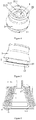
Figure 4 is one stereographic schematic diagram of the invention; -
Figure 5 is another stereographic schematic diagram of the invention; -
Figure 6 is a sectional view of the invention under maximum vertical load; -
Figure 7 is an enlarged view at C inFigure 6 ; -
Figure 8 is an enlarged view at D inFigure 6 ; -
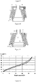
Figure 9 is a vertical stiffness curve of the invention; -
Figure 10 is a sectional view of the invention before improvement; -
Figure 11 is a sectional view of the invention before improvement under maximum vertical load; and -
Figure 12 is a vertical stiffness curve of the invention before improvement. - Legends: 1. inner conical body; 11. inner conical body lug boss; 111. lug boss transition edge; 2. rubber body; 21. annular straight section; 211. first annular straight section; 212. second annular straight section; 213. third annular straight section; 214. fourth annular straight section; 215. fifth annular straight section; 22. annular fillet section; 3. outer conical body.
- The invention will be further described as below with reference to embodiments and the drawings.
- As shown in
Figure 1 to Figure 5 , a conical spring, comprising an inner conical body 1, arubber body 2 and an outerconical body 3, wherein the lower end of the inner conical body 1 extends to the outer side to form an annular inner conicalbody lug boss 11. As shown inFigure 1 and Figure 2 , the upper end surface of therubber body 2 is of a multi-section downslope structure of three sections which are a first annularstraight section 211, a second annularstraight section 212 and a third annularstraight section 213 respectively, and every two annular straight sections adopt theannular fillet section 22 for transition. The so-called multi-section downslope structure is a gradually descending trend of therubber body 2 from the joint with the outerconical body 3 to the inner conical body 1 of therubber body 2. As shown inFigure 1 and Figure 3 , the lower end surface of therubber body 2 is of a multi-section upslope structure of two sections which are a fourth annularstraight section 214 and a fifth annularstraight section 215 respectively, and the fourth annularstraight section 214 and the fifth annularstraight section 215 also adopt theannular fillet section 22 for transition. The so-called multi-section upslope structure is a gradually ascending trend of therubber body 2 from the joint with the inner conical body 1 to the outerconical body 3 of therubber body 2. In this embodiment, the fillet radius of theannular fillet section 22 of the lower end surface of therubber body 2 is 15-25 mm, and fillet radii of the twoannular fillet sections 22 of the upper end of therubber body 2 are both 4-8 mm. Therubber body 2 encircles the periphery of the inner conical body 1, and the outerconical body 3 encircles the periphery of therubber body 2. The inner conical body 1 and the outerconical body 3 are metal components, the inner conical body 1 and the outerconical body 3, and therubber body 2 are vulcanized into a whole through an adhesive at certain temperature and pressure. The effects thereof are: the rubber body achieves the effects of shock absorption and noise reduction, and the inner conical body 1 and the outerconical body 3 achieve the effects of support and installation interface. - As shown at E and F in
Figure 10 , in the current conical spring, both the upper end and the lower end of therubber body 2 adopt a shape of combining a straight section with an arc section. In such structure, when therubber body 2 bears the maximum vertical load, corresponding folds at E and F inFigure 11 may occur to the upper end surface and the lower end surface of therubber body 2, which will cause cracks of therubber body 2 over time; because the conical spring is a whole formed by vulcanizing metal and rubber, which cannot be disassembled and cannot be conveniently repaired locally, the conical spring is a lifelong maintenance-free product, so that the conical spring is replaced if therubber body 2 cracks. - To prevent the upper end of the
rubber body 2 from folding, the structure used in this embodiment is as shown inFigure 1 and Figure 2 . The upper end of therubber body 2 is formed into a whole by the first annularstraight section 211, the second annularstraight section 212, the third annularstraight section 213 and twoannular fillet sections 22. The first annularstraight section 211 and the second annularstraight section 212 adopt theannular fillet sections 22 for transition, and the second annularstraight section 212 and the third annularstraight section 213 also adopt theannular fillet sections 22 for transition. In the process of downwards moving therubber body 2 when being subjected to vertical load, because the outer side of therubber body 2 is connected to the inner side of the outerconical body 3, the movement of the upper end and outer side of therubber body 2 may be restricted by the outerconical body 3. Thus, in the process of downwards moving therubber body 2 when being subjected to vertical load, the change of the shape of the upper end of therubber body 2 may be affected by multiple factors such as the slope and length of each annularstraight section 21, inside slope of the outerconical body 3 and the like. - For example, any one of the first annular
straight section 211 and the second annular straight section is inwards tilted rather than outwards tilted as inFigure 1 . Alternatively, if the length of any one of the first annularstraight section 211, the second annularstraight section 212 and the third annularstraight section 213 is too large, the shape of the upper end of therubber body 2 may present a fold similar to that at E inFigure 11 in the process of downwards moving therubber body 2. As shown in the following Table, the Table shows the included angle between each annular straight section of therubber body 2 in this embodiment and the vertical direction and the length of each annular straight section.Included angle (degree) between annular straight section and vertical direction Length (mm) of annular straight section First annular straight section 14-17 (a in Figure 1 )18-22 Second annular straight section 44-47(b in Figure 1 )20-23 Third annular straight section 14-16 (c in Figure 1 )11-15 Fourth annular straight section 9-11 (d in Figure 1 )49-52 Fifth annular straight section 86-88 (e in Figure 1 )5-8 - As shown in
Figure 1 and Figure 2 , when the conical spring is subjected to the downward pressure of the vertical load, therubber body 2 downwards moves, and the shape of the upper end of therubber body 2 may change. Because the slope and length of each of the first annularstraight section 211, the second annularstraight section 212 and the third annularstraight section 213 and the fillet radius of theannular fillet section 22 are designed reasonably, in the process in downwards moving therubber body 2, the shape of the upper end of therubber body 2 may be always kept as a smooth shape. The upper end of therubber body 2 may be prevented from folding, so that the upper end of the rubber body may be prevented from cracking. When the conical spring is subjected to the downward pressure of the maximum vertical load, the shape of the upper end of therubber body 2 may present a smooth shape as shown at C inFigure 6 . - As shown in
Figure 1, Figure 3 andFigure 5 , the lower end of the inner conical body 1 extends to the outer side to form an annular inner conicalbody lug boss 11, the lower end of therubber body 2 is located above the inner conicalbody lug boss 11, a fourth annularstraight section 214 and a fifth annularstraight section 215 are provided at the lower end of therubber body 2, and the fourth annularstraight section 214 and the fifth annularstraight section 215 adopt theannular fillet section 22 for transition. When the conical spring is subjected to the downward pressure of the vertical load, the lower end of therubber body 2 downwards moves and changes in shape, but the change in shape of the lower end of therubber body 2 is restricted by both the inner side of the outerconical body 3 and the inner conicalbody lug boss 11. Therefore, the lower end of therubber body 2 may be fitted with the inner conicalbody lug boss 11 and the inner side of the outerconical body 3, the inner conicalbody lug boss 11 and the lugboss transition edge 111 adopt a gentle straight line edge for transition, so that a smooth shape may be formed when the lower end of therubber body 2 is fitted with the inner conicalbody lug boss 11 and the inner side of the outerconical body 3. The lower end of therubber body 2 may be prevented from folding, so that the lower end of therubber body 2 may be prevented from cracking. When the conical spring is subjected to the downward pressure of the maximum vertical load, the shape of the lower end of therubber body 2 may present a smooth shape as shown at D inFigure 6 , also see that shown inFigure 8 . - As shown in
Figure 1 and Figure 2 , because the first annularstraight section 211 and the second annularstraight section 212 of therubber body 2 adopt theannular fillet section 22 for transition, and the second annularstraight section 212 and the third annularstraight section 213 also adopt theannular fillet section 22 for transition, when the conical spring is subjected to the downward pressure of the vertical load to make the upper end of therubber body 2 downwards move, the shape of theupper end surface 21 of therubber body 2 is always changed from theannular fillet section 22, thus, the positions of vertical changeable stiffness, transverse changeable stiffness and longitudinal changeable stiffness of the conical spring may be adjusted by changing the length of the annularstraight section 21; the number of times of changing vertical stiffness, transverse stiffness and longitudinal stiffness may be increased by increasing the number of the annularstraight sections 21; and the vertical changeable stiffness, transverse changeable stiffness and longitudinal changeable stiffness of the conical spring may be adjusted by changing the slope of the annularstraight section 21. - Because the requirements of the locomotive for the stiffness of the conical spring are different in different conditions, when the locomotive is under no load, it is required that the conical spring should not have too large stiffness but should have good elasticity, so that good elasticity refers that a good effect of shock absorption may be achieved since the stiffness of conical spring may be not suddenly increased even if the pressure of the load of the locomotive on the conical spring is suddenly increased. However, after the locomotive is under load, especially under the maximum load, it is required that the conical spring should have large stiffness and should have good elasticity, which requires that the conical spring should have good changeable stiffness to meet the stiffness requirements of the locomotive in various cases.
- As shown in
Figure 10 , because of having no structures of annular straight sections andannular fillet sections 22, the conical spring at present cannot achieve multiple changes of stiffness. The vertical stiffness curves of the conical spring at present are as shown inFigure 12 , and there are two vertical stiffness curves in the Figure, wherein the curve located on the upper part is a vertical stiffness curve when the locomotive is loaded, and the curve located on the lower part is a vertical stiffness curve when the locomotive is unloaded. At present, under no load, according to different models of locomotives, each conical spring is subjected to a vertical load of about 14KN-18KN, it can be seen fromFigure 12 that 14KN-18KN is at the inverse S curve of the vertical stiffness of the conical spring. The inverse S curve has the characteristic that the distance of downward movement of therubber body 2 is not large, but the stiffness thereof is increased quickly, and such stiffness increase mode is not beneficial to the shock absorption of the locomotive, which may cause the risk of derail of the locomotive. - As shown in
Figure 1, Figure 2 andFigure 4 , in this embodiment, three annularstraight sections 21 and twoannular fillet sections 22 of the upper end ofrubber body 2 enable the conical spring to achieve two vertical, transverse and longitudinal stiffness changes. The vertical stiffness curves of the conical spring in this embodiment are as shown inFigure 9 , and there are two vertical stiffness curves in the Figure, wherein the curve located on the upper part is a vertical stiffness curve when the locomotive is loaded, and the curve located on the lower part is a vertical stiffness curve when the locomotive is unloaded. Because of the structure of two vertical stiffness changes in this embodiment, when the conical spring is subjected to the downward pressure of the vertical load suddenly increased, the distance of downward movement of therubber body 2 is also large, thereby achieving good effects of buffering and shock absorption. It can be seen fromFigure 9 that the inverse S curve of the vertical stiffness of the conical spring is already eliminated in this embodiment. Similarly, when the locomotive accelerates, decelerates or makes a turn, because of the structure of the three annularstraight sections 21 and twoannular fillet sections 22 of the upper end of therubber body 2, the conical spring has two stiffness changes in the transverse direction and the longitudinal direction, and achieves good effects of buffering and shock absorption in the transverse direction and the longitudinal direction. Thus, the locomotive is more steady and smooth while the locomotive accelerates, decelerates or makes a turn, thereby increasing the comfortableness of passengers in the locomotive. - As shown in
Figure 6 ,Figure 7 and Figure 8 , when the conical spring bears the maximum vertical load, the change in shape when the lower end of therubber body 2 downwards moves may be restricted by the inner side of the outerconical body 3 and the inner conicalbody lug boss 11, so that the lower end of therubber body 2 enables the stiffness of the conical spring to be substantially increased. When the conical spring bears the maximum vertical load, the change in shape of the upper end of therubber body 2 may also be restricted by the inner side of the outerconical body 3 and the shape of the lower end of therubber body 2, so that the upper end of therubber body 2 may bear the maximum vertical load, and a smooth shape is formed under the maximum vertical load. Just because the conical spring still can bear the load using therubber body 2 under the maximum vertical load, the conical spring still can have good effects of buffering, shock absorption and noise reduction under the maximum vertical load. - It can be seen in this embodiment that for the five annular
straight sections 21 and threeannular fillet sections 22 of the upper end surface of therubber body 2 of the conical spring and the lower end surface of therubber body 2, three stiffness changes are formed. Moreover, the changeable stiffness of the conical spring may be changed by changing the length or slope of any one of the five annularstraight sections 21 during manufacture, that is to say, the changeable stiffness of the conical spring may be changed by adjusting the length or slope of the annular straight section. When the vertical load is not large, for the conical spring, because of the above-mentioned three stiffness changes, the conical spring may have good effects of buffering and shock absorption; when the vertical load is large and even reaches the maximum vertical load, as shown inFigure 6 , both the upper end of therubber body 2 of the conical spring and the lower end of therubber body 2 are in a smooth shape without stiffness change. Therefore, it can be seen fromFigure 9 that the stiffness change thereof is not as gentle as that under small load. However, because under the maximum vertical load, the conical spring can still bear load using therubber body 2, the conical spring can still have good effects of buffering, shock absorption and noise reduction at this moment. The design of the five annularstraight sections 21 and threeannular fillet sections 22 in this embodiment enables the shapes of both the upper end and the lower end of therubber body 2 to have no fold in the process that the conical spring bears no load to bears the maximum vertical load, thereby preventing therubber body 2 from cracking. - As approximately the same as the structure in embodiment 1, the upper end surface of the
upper rubber body 2 and the lower end surface of therubber body 2, and the lugboss transition edge 111 adopt gentle curve edge for transition rather than non-gentle straight line edge for transition. The upper end of therubber body 2 is divided into four annularstraight sections 21 and threeannular fillet sections 22, while the lower end of therubber body 2 is divided into three annularstraight sections 21 and twoannular fillet sections 22. In this way, the number of times of stiffness changes of the conical spring may be changed by changing the number of annularstraight sections 21, that is to say, the number of times of stiffness changes of the conical spring may be changed by adjusting the number of annularstraight sections 21. Increasing or reducing the number of annularstraight sections 21 still enables the shapes of both the upper end and the lower end of therubber body 2 to have no fold in the process that the conical spring bears no load to bears the maximum vertical load and to be kept as smooth shapes always. - It can be seen through the above-mentioned embodiment that the invention relates to a method for changing stiffness and preventing folds and cracks of a conical spring. The conical spring comprises an inner conical body, a rubber body and an outer conical body. The rubber body encircles the periphery of the inner conical body. The outer conical body encircles the periphery of the rubber body. The rubber body, the inner conical body and the outer conical body form a conical rubber metal spring together. The method of the invention has the characteristic that an upper rubber profile of the rubber body and a lower rubber profile of the rubber body of the conical spring adopt a multi-segment structural form, wherein the upper rubber profile of the rubber body is of a multi-section downslope structure, and the lower rubber profile of the rubber body is of a multi-section upslope structure; for the conical spring, the size of stiffness change and the position of stiffness change of the conical spring are adjusted by adjusting the shape, slope and length of each section in the multi-section downslope structure of the upper rubber profile of the rubber body and the multi-section upslope structure of the lower rubber profile of the rubber body, and the adjustment of multiple stiffness changes is achieved by controlling the number of multiple sections.
- Further, in the multi-section downslope structure of the upper rubber profile of the rubber body, the shape of each section is a straight line or arc shape, every two sections are connected through an arc section transition, to guarantee that in the process of downwards moving the upper end of the rubber body, the shape of the upper end of the rubber body is always kept as a smooth shape, so that no fold and crack may be generated.
- Further, in the multi-section upslope structure of the lower rubber profile of the rubber body, the shape of each section is a straight line or arc shape, every two sections are connected through arc section transition, to guarantee that in the process of downwards moving the rubber body, the shape of the lower end surface of the rubber body is always kept as a smooth shape, so that no fold and crack may be generated.
- Further, a lug boss is externally protruded from the bottom of the inner conical body, and after the rubber body downwards moves to the lower end surface of the rubber body and comes into contact with the lug boss, substantial changeable stiffness is generated by the cooperation of double restriction of the lug boss externally protruded from the bottom of the inner conical body and the inner side of the outer conical body; under the action of vertical load, the lower end surface of the rubber body is simultaneously closely fitted with the inner side of the outer conical body and the externally protruded lug boss of the lower part of the inner conical body gradually in a rolling mode, to achieve substantial changeable stiffness.
- Further, the upper surface of the lug boss is of a multi-section structure, every two sections adopt an arc section for transition, the size of stiffness change and the position of stiffness change are adjusted by adjusting the shape, slope and length of each section of the lug boss and the opening angle of the inner side of the outer conical body, and the adjustment multiple of stiffness changes is achieved by controlling the number of multiple sections.
- Obviously, several simple improvements or modifications may be made without departing from the principle of the invention, all of which shall be considered to belong to the protection scope of the invention.
Claims (13)
- A method for changing stiffness and preventing folding and cracking of a conical spring is provided. The conical spring comprises an inner conical body, a rubber body and an outer conical body. The rubber body encircles the periphery of the inner conical body. The outer conical body encircles the periphery of the rubber body. The rubber body, the inner conical body and the outer conical body form a conical rubber metal spring together. The method of the invention characterized in that an upper rubber profile of the rubber body and a lower rubber profile of the rubber body of the conical spring adopt a multi-segment structural form, wherein the upper rubber profile of the rubber body is of a multi-section downslope structure, and the lower rubber profile of the rubber body is of a multi-section upslope structure; for the conical spring, the size of stiffness change and the position of stiffness change of the conical spring are adjusted by adjusting the shape, slope and length of each section in the multi-section downslope structure of the upper rubber profile of the rubber body and the multi-section upslope structure of the lower rubber profile of the rubber body, and the adjustment of multiple stiffness changes is achieved by controlling the number of multiple sections.
- The method for changing stiffness and preventing folding and cracking of a conical spring according to claim 1, characterized in that in the multi-section downslope structure of the upper rubber profile of the rubber body, the shape of each section is a straight line or arc shape, and every two sections are connected through arc section transition, to guarantee that in the process of downwards moving the upper end of the rubber body, the shape of the upper end of the rubber body is always kept as a smooth shape, so that no fold and crack may be generated.
- The method for changing stiffness and preventing folds and cracks of a conical spring according to claim 1, characterized in that in the multi-section upslope structure of the lower rubber profile of the rubber body, the shape of each section is a straight line or arc shape, every two sections are connected through arc section transition, to guarantee that in the process of downwards moving the rubber body, the shape of the lower end surface of the rubber body is always kept as a smooth shape, so that no fold and crack may be generated.
- The method for changing stiffness and preventing folds and cracks of a conical spring according to claim 2 or 3, characterized in that a lug boss is externally protruded from the bottom of the inner conical body, and after the rubber body downwards moves to the lower end surface of the rubber body and comes into contact with the lug boss, substantial changeable stiffness is generated by the cooperation of double restriction of the lug boss externally protruded from the bottom of the inner conical body and the inner side of the outer conical body; under the action of vertical load, the lower end surface of the rubber body is simultaneously closely fitted with the inner side of the outer conical body and the externally protruded lug boss of the lower part of the inner conical body gradually in a rolling mode, to achieve substantial changeable stiffness.
- The method for changing stiffness and preventing folds and cracks of a conical spring according to claim 1, characterized in that the upper surface of the lug boss is of a multi-section structure, every two sections adopt an arc section for transition, the size of stiffness change and the position of stiffness change are adjusted by adjusting the shape, slope and length of each section of the lug boss and the opening angle of the inner side of the outer conical body, and the adjustment of multiple stiffness changes is achieved by controlling the number of multiple sections.
- A conical spring for carrying out the above method for changing stiffness and preventing folding and cracking of the conical spring according to claim 1, which comprises an inner conical body, a rubber body and an outer conical body. The rubber body encircles the periphery of the inner conical body. The outer conical body encircles the periphery of the rubber body. The rubber body, the inner conical body and the outer conical body form a conical rubber metal spring together; the method of the invention characterized in that an upper rubber profile of the rubber body of the conical spring and a lower rubber profile of the rubber body adopt a multi-section structure form, wherein the upper rubber profile of the rubber body is of a multi-section downslope structure form, and the lower rubber profile of the rubber body is of a multi-section upslope structure.
- The conical spring according to claim 6, characterized in that in the multi-section downslope structure of the upper rubber profile of the rubber body, the shape of each section is a straight line or arc shape, every two sections adopt an arc section for transition, to guarantee that in the process of downwards moving the upper end of the rubber body, the shape of the upper end of the rubber body is always kept as a smooth shape, so that no fold and crack may be generated.
- The conical spring according to claim 7, characterized in that the cross-section of the multi-section downslope structure is combined by two straight lines or more, and every two straight lines adopt an arc for transition, each line is different in slope and length, to guarantee that in the process of downwards moving the upper end of the rubber body, the shape of the upper end of the rubber body is always kept as a smooth shape, so that no fold and crack may be generated.
- The conical spring according to claim 7, characterized in that the cross-section of the multi-section downslope structure is combined by three straight lines, the first line is 18-22 mm, the angle between the first line and the axis is 14-17 degree; the second line is 44-47 mm, the angle between the second line and the axis is 20-23 degree; the third line is 14-16 mm, the angle between the third line and the axis is 11-15 degree.
- The conical spring according to claim 6, characterized in that in the multi-section upslope structure of the lower rubber profile of the rubber body, the shape of each section is a straight line or arc shape, every two sections adopt an arc section for transition, to guarantee that in the process of downwards moving the rubber body, the shape of the lower end surface of the rubber body is always kept as a smooth shape, so that no fold and crack may be generated.
- The conical spring according to claim 10, characterized in that the cross-section of the multi-section upslope structure is combined by two straight lines, the first line is 49-52 mm, the angle between the first line and the axis is 9-11 degree; the second line is 5-8 mm, the angle between the second line and axis is 86-88 degree.
- The conical spring according to claim 9 or 11, characterized in that a lug boss is externally protruded from the bottom of the inner conical body, after the rubber body downwards moves to the lower end surface of the rubber body and comes into contact with the lug boss, substantial changeable stiffness is generated by the cooperation of double restriction of the lug boss externally protruded from the bottom of the inner conical body and the inner side of the outer conical body; under the action of vertical load, the lower end surface of the rubber body is simultaneously closely fitted with the inner side of the outer conical body and the externally protruded lug boss of the lower part of the inner conical body gradually in a rolling mode, to achieve substantial changeable stiffness.
- The conical spring according to claim 9, characterized in that the upper surface of the lug boss is of a multi-section structure, every two sections adopt an arc section for transition, and the size of stiffness change and the position of stiffness change are adjusted by adjusting the shape, slope and length of each section of the lug boss and the opening angle of the inner side of the outer conical body; and the adjustment of multiple stiffness changes is achieved by controlling the number of multiple sections.
Applications Claiming Priority (2)
| Application Number | Priority Date | Filing Date | Title |
|---|---|---|---|
| CN201510115772.4A CN106032831B (en) | 2015-03-17 | 2015-03-17 | A kind of volute spring variation rigidity and the method and product for preventing fold and cracking |
| PCT/CN2015/075053 WO2016145668A1 (en) | 2015-03-17 | 2015-03-25 | Method and product for conical spring having variable stiffness and capable of preventing folding and cracking |
Publications (4)
| Publication Number | Publication Date |
|---|---|
| EP3273091A1 true EP3273091A1 (en) | 2018-01-24 |
| EP3273091A4 EP3273091A4 (en) | 2018-05-02 |
| EP3273091C0 EP3273091C0 (en) | 2025-06-25 |
| EP3273091B1 EP3273091B1 (en) | 2025-06-25 |
Family
ID=56918307
Family Applications (1)
| Application Number | Title | Priority Date | Filing Date |
|---|---|---|---|
| EP15885051.1A Active EP3273091B1 (en) | 2015-03-17 | 2015-03-25 | Method and product for conical spring having variable stiffness and capable of preventing folding and cracking |
Country Status (4)
| Country | Link |
|---|---|
| EP (1) | EP3273091B1 (en) |
| CN (1) | CN106032831B (en) |
| ES (1) | ES3041737T3 (en) |
| WO (1) | WO2016145668A1 (en) |
Families Citing this family (12)
| Publication number | Priority date | Publication date | Assignee | Title |
|---|---|---|---|---|
| JP6731841B2 (en) * | 2016-12-21 | 2020-07-29 | Toyo Tire株式会社 | Axial spring |
| IT201700083451A1 (en) * | 2017-07-21 | 2019-01-21 | Ari Automotive Res Innovation S A S Di Francesca Bianco & C | Connection organ controllable via a magnetic field. |
| CN108930742A (en) * | 2018-08-15 | 2018-12-04 | 株洲时代新材料科技股份有限公司 | A kind of rubber pad and stiffness tuning method of adjustable axial rigidity |
| CN108999905A (en) * | 2018-08-15 | 2018-12-14 | 株洲时代新材料科技股份有限公司 | A kind of rubber pad and stiffness tuning method of adjustable deflection rigidity |
| CN108930741A (en) * | 2018-08-15 | 2018-12-04 | 株洲时代新材料科技股份有限公司 | A kind of rubber pad and stiffness tuning method of adjustable rigidity |
| CN110285173A (en) * | 2019-07-11 | 2019-09-27 | 株洲时代新材料科技股份有限公司 | Method and structure for adjusting the stiffness of a conical spring |
| CN113323958B (en) * | 2021-07-13 | 2022-03-22 | 株洲时代新材料科技股份有限公司 | Design method for rubber profile of compression-resistant rod end ball hinge |
| CN113503309B (en) * | 2021-07-13 | 2022-03-18 | 株洲时代新材料科技股份有限公司 | Method for reducing deflection torsional rigidity of multilayer rod end spherical hinge and multilayer rod end spherical hinge |
| CN113530964B (en) * | 2021-07-13 | 2022-03-18 | 株洲时代新材料科技股份有限公司 | Integral design method of multilayer rod end spherical hinge |
| CN113503310B (en) * | 2021-07-13 | 2022-04-01 | 株洲时代新材料科技股份有限公司 | Method for improving tensile property of rubber layer of rod end spherical hinge |
| CN115929842A (en) * | 2023-01-05 | 2023-04-07 | 株洲时代瑞唯减振装备有限公司 | Vibration reduction method for driving motor of metro vehicle and composite vibration reduction mounting pad |
| CN116476884B (en) * | 2023-04-20 | 2025-05-06 | 株洲时代瑞唯减振装备有限公司 | A kind of primary rubber spring for subway vehicles |
Family Cites Families (14)
| Publication number | Priority date | Publication date | Assignee | Title |
|---|---|---|---|---|
| DE1916404A1 (en) * | 1969-03-31 | 1970-10-08 | Linke Hofmann Busch | Suspension for bogies of rail vehicles |
| DE19702947C2 (en) * | 1997-01-28 | 1999-05-27 | Contitech Formteile Gmbh | Axle suspension device for a rail vehicle |
| JP2002295584A (en) * | 2001-03-29 | 2002-10-09 | Tokai Rubber Ind Ltd | Anti-vibration rubber device |
| DE102005005915A1 (en) * | 2004-10-25 | 2006-04-27 | Gummi-Metall-Technik Gmbh | Primary spring arrangement, in particular for wagon bogies of rail vehicles |
| JP5069974B2 (en) * | 2007-08-24 | 2012-11-07 | 東洋ゴム工業株式会社 | Vehicle suspension system |
| CN201232725Y (en) * | 2008-07-24 | 2009-05-06 | 株洲时代新材料科技股份有限公司 | Vertical stiffness-changing rubber metal stacking spring suitable for big load behavior |
| CN201461844U (en) * | 2009-06-30 | 2010-05-12 | 武汉船舶设计研究所 | Metal rubber vibration isolator |
| CN102401084A (en) * | 2010-09-15 | 2012-04-04 | 溧阳市振大铁路设备有限公司 | Axle box spring of urban rail train bogie |
| CN201934559U (en) * | 2010-12-21 | 2011-08-17 | 宁波泛亚汽车部件有限公司 | Shockproof rubber bushing |
| CN202326859U (en) * | 2011-11-11 | 2012-07-11 | 上海骆氏减震件有限公司 | Suspending rubber mainspring |
| CN203702951U (en) * | 2014-02-27 | 2014-07-09 | 北京航材百慕合力高分子材料有限公司 | V-shaped rubber supporting part |
| CN204037583U (en) * | 2014-08-19 | 2014-12-24 | 株洲名扬橡塑有限公司 | A kind of railway heavy-duty freight car bogie truck journal box spring |
| CN204077689U (en) * | 2014-09-16 | 2015-01-07 | 株洲时代新材料科技股份有限公司 | A kind of heavy axle load wagon pendulum-type bogie truck axle box rubber spring |
| CN204061675U (en) * | 2014-09-16 | 2014-12-31 | 株洲时代新材料科技股份有限公司 | A kind of corrosion resistant volute spring |
-
2015
- 2015-03-17 CN CN201510115772.4A patent/CN106032831B/en active Active
- 2015-03-25 EP EP15885051.1A patent/EP3273091B1/en active Active
- 2015-03-25 ES ES15885051T patent/ES3041737T3/en active Active
- 2015-03-25 WO PCT/CN2015/075053 patent/WO2016145668A1/en not_active Ceased
Also Published As
| Publication number | Publication date |
|---|---|
| ES3041737T3 (en) | 2025-11-14 |
| EP3273091C0 (en) | 2025-06-25 |
| CN106032831A (en) | 2016-10-19 |
| EP3273091A4 (en) | 2018-05-02 |
| EP3273091B1 (en) | 2025-06-25 |
| CN106032831B (en) | 2018-07-17 |
| WO2016145668A1 (en) | 2016-09-22 |
Similar Documents
| Publication | Publication Date | Title |
|---|---|---|
| EP3273091B1 (en) | Method and product for conical spring having variable stiffness and capable of preventing folding and cracking | |
| CN104675896B (en) | Volute spring rubber bodies lower surface and the method for preventing fold and cracking | |
| CN205652140U (en) | Bogie and have rail vehicle of this bogie | |
| WO2022001463A1 (en) | Articulated bogie with embedded vibration and noise reduction apparatus | |
| WO2015101094A1 (en) | Two-stage-rigidity combination elastic-member device | |
| CN107776602B (en) | Method and structure for changing rigidity of axle box positioning node by adjusting rubber layer parameters | |
| CN110285173A (en) | Method and structure for adjusting the stiffness of a conical spring | |
| CN205652139U (en) | Rail vehicle bogie draw gear of central authorities and bogie | |
| CN204716849U (en) | A kind of volute spring with large carrying variation rigidity ability | |
| CN115507143B (en) | A special-shaped rubber spring and a method for adjusting its stiffness | |
| CN106627638A (en) | Method for adjusting thickness of rubber layers to prevent axle box bearing from being abraded and tumbler joints | |
| CN104864009B (en) | The method and product of a kind of volute spring significantly variation rigidity | |
| CN110217255A (en) | Rod node component and its design method | |
| RU2675337C1 (en) | Passive control for three-piece truck of railcar | |
| WO2015101095A1 (en) | Variable-rigidity positioning device for bogie axlebox of railway car | |
| CN104675895A (en) | Upper end surface of tapered spring rubber body, and method and product for preventing folds and cracks | |
| CN207345830U (en) | Axle box guidance joint | |
| EP3135553B1 (en) | Method to prevent rupture of steel spring | |
| CN204878483U (en) | Can prevent cone spring of physically lower terminal surface fold of rubber and fracture | |
| CN110654411B (en) | An elastic anti-roll device for railway freight cars | |
| CN106476837A (en) | A kind of waveform backstop with wearing plate and the method preventing steel spring fracture | |
| CN204477145U (en) | A kind of volute spring that can prevent rubber body upper-end surface fold and cracking | |
| CN202320358U (en) | Combined rubber horizontal buffer | |
| CN209064101U (en) | An automatic centering dual-axle bogie system for new wheel-rail trains | |
| CN109398400B (en) | Automatic centering double-shaft bogie system for new wheel-rail train |
Legal Events
| Date | Code | Title | Description |
|---|---|---|---|
| STAA | Information on the status of an ep patent application or granted ep patent |
Free format text: STATUS: THE INTERNATIONAL PUBLICATION HAS BEEN MADE |
|
| PUAI | Public reference made under article 153(3) epc to a published international application that has entered the european phase |
Free format text: ORIGINAL CODE: 0009012 |
|
| STAA | Information on the status of an ep patent application or granted ep patent |
Free format text: STATUS: REQUEST FOR EXAMINATION WAS MADE |
|
| 17P | Request for examination filed |
Effective date: 20170906 |
|
| AK | Designated contracting states |
Kind code of ref document: A1 Designated state(s): AL AT BE BG CH CY CZ DE DK EE ES FI FR GB GR HR HU IE IS IT LI LT LU LV MC MK MT NL NO PL PT RO RS SE SI SK SM TR |
|
| AX | Request for extension of the european patent |
Extension state: BA ME |
|
| A4 | Supplementary search report drawn up and despatched |
Effective date: 20180406 |
|
| RIC1 | Information provided on ipc code assigned before grant |
Ipc: F16F 1/393 20060101AFI20180329BHEP |
|
| DAV | Request for validation of the european patent (deleted) | ||
| DAX | Request for extension of the european patent (deleted) | ||
| STAA | Information on the status of an ep patent application or granted ep patent |
Free format text: STATUS: EXAMINATION IS IN PROGRESS |
|
| 17Q | First examination report despatched |
Effective date: 20211104 |
|
| REG | Reference to a national code |
Ref country code: DE Ref legal event code: R079 Free format text: PREVIOUS MAIN CLASS: F16F0015080000 Ipc: F16F0001380000 Ref country code: DE Ref legal event code: R079 Ref document number: 602015091902 Country of ref document: DE Free format text: PREVIOUS MAIN CLASS: F16F0015080000 Ipc: F16F0001380000 |
|
| GRAP | Despatch of communication of intention to grant a patent |
Free format text: ORIGINAL CODE: EPIDOSNIGR1 |
|
| RIC1 | Information provided on ipc code assigned before grant |
Ipc: F16F 1/393 20060101ALI20241212BHEP Ipc: F16F 1/38 20060101AFI20241212BHEP |
|
| STAA | Information on the status of an ep patent application or granted ep patent |
Free format text: STATUS: GRANT OF PATENT IS INTENDED |
|
| INTG | Intention to grant announced |
Effective date: 20250116 |
|
| GRAS | Grant fee paid |
Free format text: ORIGINAL CODE: EPIDOSNIGR3 |
|
| GRAA | (expected) grant |
Free format text: ORIGINAL CODE: 0009210 |
|
| STAA | Information on the status of an ep patent application or granted ep patent |
Free format text: STATUS: THE PATENT HAS BEEN GRANTED |
|
| AK | Designated contracting states |
Kind code of ref document: B1 Designated state(s): AL AT BE BG CH CY CZ DE DK EE ES FI FR GB GR HR HU IE IS IT LI LT LU LV MC MK MT NL NO PL PT RO RS SE SI SK SM TR |
|
| REG | Reference to a national code |
Ref country code: GB Ref legal event code: FG4D |
|
| REG | Reference to a national code |
Ref country code: CH Ref legal event code: EP |
|
| REG | Reference to a national code |
Ref country code: CH Ref legal event code: EP |
|
| REG | Reference to a national code |
Ref country code: IE Ref legal event code: FG4D |
|
| REG | Reference to a national code |
Ref country code: DE Ref legal event code: R096 Ref document number: 602015091902 Country of ref document: DE |
|
| U01 | Request for unitary effect filed |
Effective date: 20250705 |
|
| U07 | Unitary effect registered |
Designated state(s): AT BE BG DE DK EE FI FR IT LT LU LV MT NL PT RO SE SI Effective date: 20250711 |
|
| PG25 | Lapsed in a contracting state [announced via postgrant information from national office to epo] |
Ref country code: GR Free format text: LAPSE BECAUSE OF FAILURE TO SUBMIT A TRANSLATION OF THE DESCRIPTION OR TO PAY THE FEE WITHIN THE PRESCRIBED TIME-LIMIT Effective date: 20250926 Ref country code: NO Free format text: LAPSE BECAUSE OF FAILURE TO SUBMIT A TRANSLATION OF THE DESCRIPTION OR TO PAY THE FEE WITHIN THE PRESCRIBED TIME-LIMIT Effective date: 20250925 |
|
| PG25 | Lapsed in a contracting state [announced via postgrant information from national office to epo] |
Ref country code: HR Free format text: LAPSE BECAUSE OF FAILURE TO SUBMIT A TRANSLATION OF THE DESCRIPTION OR TO PAY THE FEE WITHIN THE PRESCRIBED TIME-LIMIT Effective date: 20250625 |
|
| PG25 | Lapsed in a contracting state [announced via postgrant information from national office to epo] |
Ref country code: RS Free format text: LAPSE BECAUSE OF FAILURE TO SUBMIT A TRANSLATION OF THE DESCRIPTION OR TO PAY THE FEE WITHIN THE PRESCRIBED TIME-LIMIT Effective date: 20250925 |
|
| REG | Reference to a national code |
Ref country code: ES Ref legal event code: FG2A Ref document number: 3041737 Country of ref document: ES Kind code of ref document: T3 Effective date: 20251114 |
|
| PG25 | Lapsed in a contracting state [announced via postgrant information from national office to epo] |
Ref country code: IS Free format text: LAPSE BECAUSE OF FAILURE TO SUBMIT A TRANSLATION OF THE DESCRIPTION OR TO PAY THE FEE WITHIN THE PRESCRIBED TIME-LIMIT Effective date: 20251025 |
|
| PG25 | Lapsed in a contracting state [announced via postgrant information from national office to epo] |
Ref country code: SM Free format text: LAPSE BECAUSE OF FAILURE TO SUBMIT A TRANSLATION OF THE DESCRIPTION OR TO PAY THE FEE WITHIN THE PRESCRIBED TIME-LIMIT Effective date: 20250625 |
|
| PG25 | Lapsed in a contracting state [announced via postgrant information from national office to epo] |
Ref country code: CZ Free format text: LAPSE BECAUSE OF FAILURE TO SUBMIT A TRANSLATION OF THE DESCRIPTION OR TO PAY THE FEE WITHIN THE PRESCRIBED TIME-LIMIT Effective date: 20250625 |
|
| PG25 | Lapsed in a contracting state [announced via postgrant information from national office to epo] |
Ref country code: PL Free format text: LAPSE BECAUSE OF FAILURE TO SUBMIT A TRANSLATION OF THE DESCRIPTION OR TO PAY THE FEE WITHIN THE PRESCRIBED TIME-LIMIT Effective date: 20250625 |
|
| PG25 | Lapsed in a contracting state [announced via postgrant information from national office to epo] |
Ref country code: SK Free format text: LAPSE BECAUSE OF FAILURE TO SUBMIT A TRANSLATION OF THE DESCRIPTION OR TO PAY THE FEE WITHIN THE PRESCRIBED TIME-LIMIT Effective date: 20250625 |
|
| U20 | Renewal fee for the european patent with unitary effect paid |
Year of fee payment: 12 Effective date: 20260108 |
|
| PGFP | Annual fee paid to national office [announced via postgrant information from national office to epo] |
Ref country code: GB Payment date: 20260121 Year of fee payment: 12 |
|
| PLBE | No opposition filed within time limit |
Free format text: ORIGINAL CODE: 0009261 |
|
| STAA | Information on the status of an ep patent application or granted ep patent |
Free format text: STATUS: NO OPPOSITION FILED WITHIN TIME LIMIT |
|
| REG | Reference to a national code |
Ref country code: CH Ref legal event code: L10 Free format text: ST27 STATUS EVENT CODE: U-0-0-L10-L00 (AS PROVIDED BY THE NATIONAL OFFICE) Effective date: 20260507 |
|
| 26N | No opposition filed |
Effective date: 20260326 |
|
| PGFP | Annual fee paid to national office [announced via postgrant information from national office to epo] |
Ref country code: ES Payment date: 20260428 Year of fee payment: 12 |