EP3272897A1 - Nanocrystalline bainitic steels, shafts, gas turbine engines, and methods of manufacturing nanocrystalline bainitic steels - Google Patents
Nanocrystalline bainitic steels, shafts, gas turbine engines, and methods of manufacturing nanocrystalline bainitic steels Download PDFInfo
- Publication number
- EP3272897A1 EP3272897A1 EP17157656.4A EP17157656A EP3272897A1 EP 3272897 A1 EP3272897 A1 EP 3272897A1 EP 17157656 A EP17157656 A EP 17157656A EP 3272897 A1 EP3272897 A1 EP 3272897A1
- Authority
- EP
- European Patent Office
- Prior art keywords
- nanocrystalline
- shaft
- low pressure
- steel
- bainitic
- Prior art date
- Legal status (The legal status is an assumption and is not a legal conclusion. Google has not performed a legal analysis and makes no representation as to the accuracy of the status listed.)
- Granted
Links
Images


Classifications
-
- C—CHEMISTRY; METALLURGY
- C21—METALLURGY OF IRON
- C21D—MODIFYING THE PHYSICAL STRUCTURE OF FERROUS METALS; GENERAL DEVICES FOR HEAT TREATMENT OF FERROUS OR NON-FERROUS METALS OR ALLOYS; MAKING METAL MALLEABLE, e.g. BY DECARBURISATION OR TEMPERING
- C21D6/00—Heat treatment of ferrous alloys
- C21D6/001—Heat treatment of ferrous alloys containing Ni
-
- C—CHEMISTRY; METALLURGY
- C21—METALLURGY OF IRON
- C21D—MODIFYING THE PHYSICAL STRUCTURE OF FERROUS METALS; GENERAL DEVICES FOR HEAT TREATMENT OF FERROUS OR NON-FERROUS METALS OR ALLOYS; MAKING METAL MALLEABLE, e.g. BY DECARBURISATION OR TEMPERING
- C21D1/00—General methods or devices for heat treatment, e.g. annealing, hardening, quenching or tempering
- C21D1/18—Hardening; Quenching with or without subsequent tempering
-
- C—CHEMISTRY; METALLURGY
- C21—METALLURGY OF IRON
- C21D—MODIFYING THE PHYSICAL STRUCTURE OF FERROUS METALS; GENERAL DEVICES FOR HEAT TREATMENT OF FERROUS OR NON-FERROUS METALS OR ALLOYS; MAKING METAL MALLEABLE, e.g. BY DECARBURISATION OR TEMPERING
- C21D6/00—Heat treatment of ferrous alloys
- C21D6/005—Heat treatment of ferrous alloys containing Mn
-
- C—CHEMISTRY; METALLURGY
- C21—METALLURGY OF IRON
- C21D—MODIFYING THE PHYSICAL STRUCTURE OF FERROUS METALS; GENERAL DEVICES FOR HEAT TREATMENT OF FERROUS OR NON-FERROUS METALS OR ALLOYS; MAKING METAL MALLEABLE, e.g. BY DECARBURISATION OR TEMPERING
- C21D6/00—Heat treatment of ferrous alloys
- C21D6/02—Hardening by precipitation
-
- C—CHEMISTRY; METALLURGY
- C21—METALLURGY OF IRON
- C21D—MODIFYING THE PHYSICAL STRUCTURE OF FERROUS METALS; GENERAL DEVICES FOR HEAT TREATMENT OF FERROUS OR NON-FERROUS METALS OR ALLOYS; MAKING METAL MALLEABLE, e.g. BY DECARBURISATION OR TEMPERING
- C21D9/00—Heat treatment, e.g. annealing, hardening, quenching or tempering, adapted for particular articles; Furnaces therefor
- C21D9/0068—Heat treatment, e.g. annealing, hardening, quenching or tempering, adapted for particular articles; Furnaces therefor for particular articles not mentioned below
-
- C—CHEMISTRY; METALLURGY
- C22—METALLURGY; FERROUS OR NON-FERROUS ALLOYS; TREATMENT OF ALLOYS OR NON-FERROUS METALS
- C22C—ALLOYS
- C22C38/00—Ferrous alloys, e.g. steel alloys
- C22C38/04—Ferrous alloys, e.g. steel alloys containing manganese
-
- C—CHEMISTRY; METALLURGY
- C22—METALLURGY; FERROUS OR NON-FERROUS ALLOYS; TREATMENT OF ALLOYS OR NON-FERROUS METALS
- C22C—ALLOYS
- C22C38/00—Ferrous alloys, e.g. steel alloys
- C22C38/06—Ferrous alloys, e.g. steel alloys containing aluminium
-
- C—CHEMISTRY; METALLURGY
- C22—METALLURGY; FERROUS OR NON-FERROUS ALLOYS; TREATMENT OF ALLOYS OR NON-FERROUS METALS
- C22C—ALLOYS
- C22C38/00—Ferrous alloys, e.g. steel alloys
- C22C38/10—Ferrous alloys, e.g. steel alloys containing cobalt
- C22C38/105—Ferrous alloys, e.g. steel alloys containing cobalt containing Co and Ni
-
- C—CHEMISTRY; METALLURGY
- C22—METALLURGY; FERROUS OR NON-FERROUS ALLOYS; TREATMENT OF ALLOYS OR NON-FERROUS METALS
- C22C—ALLOYS
- C22C38/00—Ferrous alloys, e.g. steel alloys
- C22C38/12—Ferrous alloys, e.g. steel alloys containing tungsten, tantalum, molybdenum, vanadium, or niobium
-
- C—CHEMISTRY; METALLURGY
- C22—METALLURGY; FERROUS OR NON-FERROUS ALLOYS; TREATMENT OF ALLOYS OR NON-FERROUS METALS
- C22C—ALLOYS
- C22C38/00—Ferrous alloys, e.g. steel alloys
- C22C38/18—Ferrous alloys, e.g. steel alloys containing chromium
- C22C38/40—Ferrous alloys, e.g. steel alloys containing chromium with nickel
- C22C38/44—Ferrous alloys, e.g. steel alloys containing chromium with nickel with molybdenum or tungsten
-
- C—CHEMISTRY; METALLURGY
- C22—METALLURGY; FERROUS OR NON-FERROUS ALLOYS; TREATMENT OF ALLOYS OR NON-FERROUS METALS
- C22C—ALLOYS
- C22C38/00—Ferrous alloys, e.g. steel alloys
- C22C38/18—Ferrous alloys, e.g. steel alloys containing chromium
- C22C38/40—Ferrous alloys, e.g. steel alloys containing chromium with nickel
- C22C38/52—Ferrous alloys, e.g. steel alloys containing chromium with nickel with cobalt
-
- F—MECHANICAL ENGINEERING; LIGHTING; HEATING; WEAPONS; BLASTING
- F01—MACHINES OR ENGINES IN GENERAL; ENGINE PLANTS IN GENERAL; STEAM ENGINES
- F01D—NON-POSITIVE DISPLACEMENT MACHINES OR ENGINES, e.g. STEAM TURBINES
- F01D25/00—Component parts, details, or accessories, not provided for in, or of interest apart from, other groups
- F01D25/005—Selecting particular materials
-
- F—MECHANICAL ENGINEERING; LIGHTING; HEATING; WEAPONS; BLASTING
- F01—MACHINES OR ENGINES IN GENERAL; ENGINE PLANTS IN GENERAL; STEAM ENGINES
- F01D—NON-POSITIVE DISPLACEMENT MACHINES OR ENGINES, e.g. STEAM TURBINES
- F01D5/00—Blades; Blade-carrying members; Heating, heat-insulating, cooling or antivibration means on the blades or the members
- F01D5/02—Blade-carrying members, e.g. rotors
-
- F—MECHANICAL ENGINEERING; LIGHTING; HEATING; WEAPONS; BLASTING
- F01—MACHINES OR ENGINES IN GENERAL; ENGINE PLANTS IN GENERAL; STEAM ENGINES
- F01D—NON-POSITIVE DISPLACEMENT MACHINES OR ENGINES, e.g. STEAM TURBINES
- F01D5/00—Blades; Blade-carrying members; Heating, heat-insulating, cooling or antivibration means on the blades or the members
- F01D5/12—Blades
- F01D5/28—Selecting particular materials; Particular measures relating thereto; Measures against erosion or corrosion
-
- F—MECHANICAL ENGINEERING; LIGHTING; HEATING; WEAPONS; BLASTING
- F01—MACHINES OR ENGINES IN GENERAL; ENGINE PLANTS IN GENERAL; STEAM ENGINES
- F01D—NON-POSITIVE DISPLACEMENT MACHINES OR ENGINES, e.g. STEAM TURBINES
- F01D5/00—Blades; Blade-carrying members; Heating, heat-insulating, cooling or antivibration means on the blades or the members
- F01D5/12—Blades
- F01D5/28—Selecting particular materials; Particular measures relating thereto; Measures against erosion or corrosion
- F01D5/286—Particular treatment of blades, e.g. to increase durability or resistance against corrosion or erosion
-
- C—CHEMISTRY; METALLURGY
- C21—METALLURGY OF IRON
- C21D—MODIFYING THE PHYSICAL STRUCTURE OF FERROUS METALS; GENERAL DEVICES FOR HEAT TREATMENT OF FERROUS OR NON-FERROUS METALS OR ALLOYS; MAKING METAL MALLEABLE, e.g. BY DECARBURISATION OR TEMPERING
- C21D2211/00—Microstructure comprising significant phases
- C21D2211/002—Bainite
-
- C—CHEMISTRY; METALLURGY
- C21—METALLURGY OF IRON
- C21D—MODIFYING THE PHYSICAL STRUCTURE OF FERROUS METALS; GENERAL DEVICES FOR HEAT TREATMENT OF FERROUS OR NON-FERROUS METALS OR ALLOYS; MAKING METAL MALLEABLE, e.g. BY DECARBURISATION OR TEMPERING
- C21D2211/00—Microstructure comprising significant phases
- C21D2211/004—Dispersions; Precipitations
-
- C—CHEMISTRY; METALLURGY
- C21—METALLURGY OF IRON
- C21D—MODIFYING THE PHYSICAL STRUCTURE OF FERROUS METALS; GENERAL DEVICES FOR HEAT TREATMENT OF FERROUS OR NON-FERROUS METALS OR ALLOYS; MAKING METAL MALLEABLE, e.g. BY DECARBURISATION OR TEMPERING
- C21D6/00—Heat treatment of ferrous alloys
- C21D6/007—Heat treatment of ferrous alloys containing Co
-
- C—CHEMISTRY; METALLURGY
- C21—METALLURGY OF IRON
- C21D—MODIFYING THE PHYSICAL STRUCTURE OF FERROUS METALS; GENERAL DEVICES FOR HEAT TREATMENT OF FERROUS OR NON-FERROUS METALS OR ALLOYS; MAKING METAL MALLEABLE, e.g. BY DECARBURISATION OR TEMPERING
- C21D7/00—Modifying the physical properties of iron or steel by deformation
- C21D7/13—Modifying the physical properties of iron or steel by deformation by hot working
-
- C—CHEMISTRY; METALLURGY
- C22—METALLURGY; FERROUS OR NON-FERROUS ALLOYS; TREATMENT OF ALLOYS OR NON-FERROUS METALS
- C22C—ALLOYS
- C22C2200/00—Crystalline structure
- C22C2200/04—Nanocrystalline
-
- F—MECHANICAL ENGINEERING; LIGHTING; HEATING; WEAPONS; BLASTING
- F05—INDEXING SCHEMES RELATING TO ENGINES OR PUMPS IN VARIOUS SUBCLASSES OF CLASSES F01-F04
- F05D—INDEXING SCHEME FOR ASPECTS RELATING TO NON-POSITIVE-DISPLACEMENT MACHINES OR ENGINES, GAS-TURBINES OR JET-PROPULSION PLANTS
- F05D2220/00—Application
- F05D2220/30—Application in turbines
- F05D2220/32—Application in turbines in gas turbines
-
- F—MECHANICAL ENGINEERING; LIGHTING; HEATING; WEAPONS; BLASTING
- F05—INDEXING SCHEMES RELATING TO ENGINES OR PUMPS IN VARIOUS SUBCLASSES OF CLASSES F01-F04
- F05D—INDEXING SCHEME FOR ASPECTS RELATING TO NON-POSITIVE-DISPLACEMENT MACHINES OR ENGINES, GAS-TURBINES OR JET-PROPULSION PLANTS
- F05D2240/00—Components
- F05D2240/60—Shafts
-
- F—MECHANICAL ENGINEERING; LIGHTING; HEATING; WEAPONS; BLASTING
- F05—INDEXING SCHEMES RELATING TO ENGINES OR PUMPS IN VARIOUS SUBCLASSES OF CLASSES F01-F04
- F05D—INDEXING SCHEME FOR ASPECTS RELATING TO NON-POSITIVE-DISPLACEMENT MACHINES OR ENGINES, GAS-TURBINES OR JET-PROPULSION PLANTS
- F05D2300/00—Materials; Properties thereof
- F05D2300/10—Metals, alloys or intermetallic compounds
- F05D2300/17—Alloys
- F05D2300/171—Steel alloys
-
- F—MECHANICAL ENGINEERING; LIGHTING; HEATING; WEAPONS; BLASTING
- F05—INDEXING SCHEMES RELATING TO ENGINES OR PUMPS IN VARIOUS SUBCLASSES OF CLASSES F01-F04
- F05D—INDEXING SCHEME FOR ASPECTS RELATING TO NON-POSITIVE-DISPLACEMENT MACHINES OR ENGINES, GAS-TURBINES OR JET-PROPULSION PLANTS
- F05D2300/00—Materials; Properties thereof
- F05D2300/60—Properties or characteristics given to material by treatment or manufacturing
- F05D2300/605—Crystalline
Definitions
- the present disclosure concerns nanocrystalline bainitic steels, shafts, gas turbine engines, and methods of manufacturing nanocrystalline bainitic steels.
- Gas turbine engines typically include a turbine module that is arranged to drive a compressor module via one or more interconnecting shafts.
- a propulsive fan is driven by a low pressure turbine via the low pressure shaft.
- the low pressure shaft comprises two shafts, specifically, a low pressure turbine shaft and a low pressure compressor shaft which are made of different materials.
- the low pressure turbine shaft and the low pressure compressor shaft are joined coaxially and end to end by a helical spline joint.
- the spline region of the low pressure turbine shaft operates at a relatively low temperature (approximately 150 Celsius), but may require a challenging combination of mechanical properties, for example, high torque carrying capability, high ultimate tensile strength, high 0.2% proof stress, and good fatigue strength. Consequently, the spline region of the low pressure turbine shaft is usually made from an alloy such as AerMet® 100. However, this alloy is not suitable for use at elevated temperatures (for example, above 400 Celsius) for extended periods of time because of over-aging of the carbide structures, which may significantly reduce the yield and tensile strengths and has an adverse effect on the creep resistance.
- the rear part of the low pressure turbine shaft is not subject to the torque loads experienced by the spline, but may reach temperatures of up to 450 Celsius for extended periods.
- the rear part of the low pressure turbine shaft is therefore usually made from an alloy such as Super-CMV which is welded to the spline region of the low pressure turbine shaft. This alloy does not have the torque carrying capability or the fatigue strength to be used in the low temperature spline region of the shaft, but the microstructure is relatively stable up to 450 Celsius giving the alloy good thermal stability and creep capability.
- the manufacture of the low pressure turbine shaft is relatively complex as it is fabricated from sections made from two different materials. Furthermore, the presence of a welded joint increases cost and manufacturing time.
- a nanocrystalline bainitic steel consisting of, by weight percentage: 0.3% to 0.6% carbon; 9.0% to 20.0% nickel; up to 10% cobalt; 1.0% to 4.5% aluminium; up to 0.5% molybdenum; up to 0.5% manganese; up to 0.5% tungsten; up to 3.0% chromium; and the balance being iron and impurities.
- the nanocrystalline bainitic steel may consist of, by weight percentage: 0.35% to 0.45% carbon; 11.0% to 15.0% nickel; 2.0% to 6.0% cobalt; 2.0% to 3.0% aluminium; 0.2% to 0.4% molybdenum; 0.05% to 0.25% manganese; up to 0.5% tungsten; up to 3% chromium; and the balance being iron and impurities.
- the nanocrystalline bainitic steel may consist of, by weight percentage: 0.4% carbon; 13.0% nickel; 4.0% cobalt; 2.5% aluminium; 0.3% molybdenum; 0.15% manganese; and the balance being iron and impurities.
- the nanocrystalline bainitic steel may comprise a plurality of nickel aluminide intermetallic particles.
- a shaft comprising the nanocrystalline bainitic steel as described in any of the preceding paragraphs.
- the shaft may be a low pressure shaft and may include a low pressure compressor shaft and a low pressure turbine shaft.
- the low pressure turbine shaft may have a first end, a second opposite end, and a longitudinal axis extending between the first end and the second end.
- the low pressure turbine shaft may have no joint between the first end and the second end.
- a gas turbine engine comprising a shaft as described in any of the preceding paragraphs.
- the low pressure shaft may extend between a low pressure turbine and a low pressure compressor, or a fan, or a gearbox.
- an object comprising the nanocrystalline bainitic steel as described in any of the preceding paragraphs.
- the method may comprise maintaining a transformation temperature of the steel between 150 Celsius and 350 Celsius.
- the method may further comprise tempering the steel to form a plurality of nickel aluminide intermetallic particles.
- Tempering the steel may be performed at a temperature between 250 Celsius and 500 Celsius.
- Figure 1 illustrates a gas turbine engine 10 having a principal and rotational axis 11.
- the engine 10 comprises, in axial flow series, an air intake 12, a propulsive fan 13, an intermediate pressure compressor 14, a high-pressure compressor 15, combustion apparatus 16, a high-pressure turbine 17, an intermediate pressure turbine 18, a low-pressure turbine 19 and an exhaust nozzle 20.
- a nacelle 21 generally surrounds the engine 10 and defines both the intake 12 and the exhaust nozzle 20.
- the gas turbine engine 10 works so that air entering the intake 12 is accelerated by the fan 13 to produce two air flows: a first air flow into the intermediate pressure compressor 14 and a second air flow which passes through a bypass duct 22 to provide propulsive thrust.
- the intermediate pressure compressor 14 compresses the air flow directed into it before delivering that air to the high pressure compressor 15 where further compression takes place.
- the compressed air exhausted from the high-pressure compressor 15 is directed into the combustion apparatus 16 where it is mixed with fuel and the mixture combusted.
- the resultant hot combustion products then expand through, and thereby drive the high, intermediate and low-pressure turbines 17, 18, 19 before being exhausted through the nozzle 20 to provide additional propulsive thrust.
- the high pressure turbine 17 drives the high pressure compressor 15 via a high pressure shaft 24.
- the intermediate pressure turbine 18 drives the intermediate pressure compressor 15 via an intermediate pressure shaft 26.
- the low pressure turbine 19 drives the fan 13 via a low pressure shaft 28 (which includes a low pressure turbine shaft 29 and a low pressure compressor shaft 31).
- gas turbine engines to which the present disclosure may be applied may have alternative configurations.
- such engines may have an alternative number of interconnecting shafts (two for example) and/or an alternative number of compressors and/or turbines.
- the engine may comprise a gearbox provided in the drive train from a turbine to a compressor and/or fan.
- the low pressure shaft 28 and/or the intermediate pressure shaft 26 and/or the high pressure shaft 24 comprise a nanocrystalline bainitic steel as described in the following paragraphs.
- the nanocrystalline bainitic steel consists of, by weight percentage: 0.3% to 0.6% carbon; 9.0% to 20.0% nickel; up to 10% cobalt; 1.0% to 4.5% aluminium; up to 0.5% molybdenum; up to 0.5% manganese; up to 0.5% tungsten; up to 3.0% chromium; and the balance being iron and impurities.
- the nickel and the aluminium may form nickel aluminide intermetallic particles in the steel.
- the nanocrystalline bainitic steel consists of, by weight percentage: 0.35% to 0.45% carbon; 11.0% to 15.0% nickel; 2.0% to 6.0% cobalt; 2.0% to 3.0% aluminium; 0.2% to 0.4% molybdenum; 0.05% to 0.25% manganese; up to 0.5% tungsten; up to 3% chromium; and the balance being iron and impurities.
- the nanocrystalline bainitic steel consists of, by weight percentage: 0.4% carbon; 13.0% nickel; 4.0% cobalt; 2.5% aluminium; 0.3% molybdenum; 0.15% manganese; and the balance being iron and impurities.
- the low pressure turbine shaft 29 may not comprise a joint between a first end 30 (coupled to the low pressure compressor shaft 31) and a second opposite end 32 (coupled to the low pressure turbine 19). In other words, the low pressure turbine shaft 29 may substantially only consist of the nanocrystalline bainitic steel.
- the nanocrystalline bainitic steel may be manufactured in accordance with the following process as described with reference to Figs. 2 and 3 .
- the method includes providing a raw material ingot for manufacturing the nanocrystalline bainitic steel.
- the raw material ingot may be homogenised.
- the raw material ingot may be heated to a homogenisation temperature of approximately 1200 Celsius for a homogenisation time period of up to about two days.
- the method includes heating the material to form a forged alloy.
- the material may be heated for hot working to a temperature in excess of 1100 Celsius and forged or rolled to a final size with a finishing temperature of above 900 Celsius.
- the forged alloy is then air cooled to ambient temperature.
- the method includes annealing the alloy.
- the alloy may be sub-critically annealed at a temperature of about 750 Celsius for a time in excess of one hour. After annealing, the alloy is air cooled to ambient temperature.
- the method includes heating the alloy to an austenitisation temperature T A .
- the range 41 of possible austenitisation temperatures is illustrated in Fig. 3 . It is usually desirable to austenitise at as low a temperature as possible (above the austenite start temperature 43) since this will minimise the size of the austenite grains. Bainite nucleates from the austenite grain boundaries and consequently, a smaller austenite grain size enables the bainite to form more quickly.
- the temperature of the alloy is maintained at the austenitisation temperature for as long as necessary to form a substantially austenitic structure. For example, the alloy may be heated to an austenitisation temperature between 950 Celsius and 1100 Celsius for a time in excess of one minute until the alloy comprises austenite only.
- the method includes cooling the alloy and then maintaining the temperature of the alloy at a transformation temperature T T (for example, between 150 Celsius and 350 Celsius).
- a transformation temperature T T for example, between 150 Celsius and 350 Celsius.
- the edges of the bar cool faster than the core (following the solid line in Fig. 3 to time B1) and reach the transformation temperature T T before the core (which follows the solid line in Fig. 3 to time B2).
- the temperature of the bar is controlled until the whole bar is at the transformation temperature T T .
- the cooling of the alloy is controlled to avoid the pearlite "nose" 45 which includes a left hand line representing the pearlite start line, and a right hand line which represents the pearlite finish line.
- the area between the pearlite start and finish lines indicates the time/temperature region in which pearlite can form in the alloy.
- line 47 is the bainite start line and line 49 is the bainite finish line.
- the area between the bainite start line 47 and the bainite finish line 49 indicates the time/temperature region in which austenite may be transformed into bainite.
- the transformation temperature T T may be any temperature within the range 50. As mentioned above, the transformation temperature T T may be any temperature within the range 150 Celsius to 350 Celsius.
- the method includes cooling the alloy to ambient temperature at time D.
- the alloy may be furnace cooled to ambient temperature.
- the method includes tempering the alloy subsequent to the bainitic transformation being completed.
- the alloy may be tempered at a temperature between 250 Celsius and 500 Celsius to form nickel aluminide intermetallic particles in the alloy.
- Performing the bainitic transformation (block 42) at relatively low temperatures causes the alloy to have a nanocrystalline structure and provides the alloy with a relatively high strength.
- the bainite plates may have a width of less than 50 nanometres.
- the nanocrystalline bainitic steel may provide several advantages.
- the steel comprises a relatively low amount of carbon (when compared to conventional 'superbainitic' steels) which reduces the carbide precipitation in the steel.
- the steel comprises relatively high amounts of nickel which stabilises the austenite to allow the formation of bainite at relatively low temperatures and produce a nanocrystalline bainitic structure. Furthermore, the relatively high amounts of nickel may improve the fracture toughness of the steel.
- the steel may be strengthened by the precipitation of nickel aluminide intermetallic particles during tempering that mitigate the loss of strength associated with carbide precipitation.
- composition of the nanocrystalline bainitic steel may enable the steel to retain the ductile phase subsequent to the tempering at block 46.
- nanocrystalline bainitic steel comprises molybdenum and/or manganese
- these elements may tie up residual impurities, and in the case of molybdenum, form high temperature secondary carbides that provide significant contributions to strength that persist to high temperatures.
- nanocrystalline bainitic steel comprises chromium and/or tungsten, these elements may contribute to secondary hardening.
- a low pressure turbine shaft may be manufactured solely from the nanocrystalline bainitic steel. This may reduce the cost and complexity of manufacturing the low pressure turbine shaft.
- the nanocrystalline bainitic steel may have relatively high fatigue strength and may be manufactured using a clean vacuum melt route to reduce the size and quantity of non-metallic inclusions.
- an object (other than a shaft) may comprise the nanocrystalline bainitic steel described in the preceding paragraphs.
Landscapes
- Chemical & Material Sciences (AREA)
- Engineering & Computer Science (AREA)
- Mechanical Engineering (AREA)
- Materials Engineering (AREA)
- Metallurgy (AREA)
- Organic Chemistry (AREA)
- Physics & Mathematics (AREA)
- Thermal Sciences (AREA)
- Crystallography & Structural Chemistry (AREA)
- General Engineering & Computer Science (AREA)
- Turbine Rotor Nozzle Sealing (AREA)
- Heat Treatment Of Articles (AREA)
Abstract
Description
- The present disclosure concerns nanocrystalline bainitic steels, shafts, gas turbine engines, and methods of manufacturing nanocrystalline bainitic steels.
- Gas turbine engines typically include a turbine module that is arranged to drive a compressor module via one or more interconnecting shafts. For example, in a 'three-shaft' gas turbine engine, a propulsive fan is driven by a low pressure turbine via the low pressure shaft. The low pressure shaft comprises two shafts, specifically, a low pressure turbine shaft and a low pressure compressor shaft which are made of different materials. The low pressure turbine shaft and the low pressure compressor shaft are joined coaxially and end to end by a helical spline joint.
- The spline region of the low pressure turbine shaft operates at a relatively low temperature (approximately 150 Celsius), but may require a challenging combination of mechanical properties, for example, high torque carrying capability, high ultimate tensile strength, high 0.2% proof stress, and good fatigue strength. Consequently, the spline region of the low pressure turbine shaft is usually made from an alloy such as AerMet® 100. However, this alloy is not suitable for use at elevated temperatures (for example, above 400 Celsius) for extended periods of time because of over-aging of the carbide structures, which may significantly reduce the yield and tensile strengths and has an adverse effect on the creep resistance.
- The rear part of the low pressure turbine shaft is not subject to the torque loads experienced by the spline, but may reach temperatures of up to 450 Celsius for extended periods. The rear part of the low pressure turbine shaft is therefore usually made from an alloy such as Super-CMV which is welded to the spline region of the low pressure turbine shaft. This alloy does not have the torque carrying capability or the fatigue strength to be used in the low temperature spline region of the shaft, but the microstructure is relatively stable up to 450 Celsius giving the alloy good thermal stability and creep capability.
- It should be appreciated from the preceding paragraphs that the manufacture of the low pressure turbine shaft is relatively complex as it is fabricated from sections made from two different materials. Furthermore, the presence of a welded joint increases cost and manufacturing time.
- According to various examples there is provided a nanocrystalline bainitic steel consisting of, by weight percentage: 0.3% to 0.6% carbon; 9.0% to 20.0% nickel; up to 10% cobalt; 1.0% to 4.5% aluminium; up to 0.5% molybdenum; up to 0.5% manganese; up to 0.5% tungsten; up to 3.0% chromium; and the balance being iron and impurities.
- The nanocrystalline bainitic steel may consist of, by weight percentage: 0.35% to 0.45% carbon; 11.0% to 15.0% nickel; 2.0% to 6.0% cobalt; 2.0% to 3.0% aluminium; 0.2% to 0.4% molybdenum; 0.05% to 0.25% manganese; up to 0.5% tungsten; up to 3% chromium; and the balance being iron and impurities.
- The nanocrystalline bainitic steel may consist of, by weight percentage: 0.4% carbon; 13.0% nickel; 4.0% cobalt; 2.5% aluminium; 0.3% molybdenum; 0.15% manganese; and the balance being iron and impurities.
- The nanocrystalline bainitic steel may comprise a plurality of nickel aluminide intermetallic particles.
- According to various examples there is provided a shaft comprising the nanocrystalline bainitic steel as described in any of the preceding paragraphs.
- The shaft may be a low pressure shaft and may include a low pressure compressor shaft and a low pressure turbine shaft. The low pressure turbine shaft may have a first end, a second opposite end, and a longitudinal axis extending between the first end and the second end. The low pressure turbine shaft may have no joint between the first end and the second end.
- According to various examples there is provided a gas turbine engine comprising a shaft as described in any of the preceding paragraphs.
- The low pressure shaft may extend between a low pressure turbine and a low pressure compressor, or a fan, or a gearbox.
- According to various examples there is provided an object comprising the nanocrystalline bainitic steel as described in any of the preceding paragraphs.
- According to various examples there is provided a method of manufacturing a nanocrystalline bainitic steel as described in any of the preceding paragraphs.
- The method may comprise maintaining a transformation temperature of the steel between 150 Celsius and 350 Celsius.
- The method may further comprise tempering the steel to form a plurality of nickel aluminide intermetallic particles.
- Tempering the steel may be performed at a temperature between 250 Celsius and 500 Celsius.
- The skilled person will appreciate that except where mutually exclusive, a feature described in relation to any one of the above aspects may be applied mutatis mutandis to any other aspect. Furthermore except where mutually exclusive any feature described herein may be applied to any aspect and/or combined with any other feature described herein.
- Embodiments will now be described by way of example only, with reference to the Figures, in which:
-
Fig. 1 illustrates a cross sectional side view of a gas turbine engine according to various examples; -
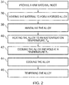
Fig. 2 illustrates a flow diagram of a method of manufacturing nanocrystalline bainitic steel according to various examples; and -
Fig. 3 illustrates a time/temperature/transformation diagram for nanocrystalline bainitic steel according to various examples. -
Figure 1 illustrates agas turbine engine 10 having a principal androtational axis 11. Theengine 10 comprises, in axial flow series, anair intake 12, apropulsive fan 13, anintermediate pressure compressor 14, a high-pressure compressor 15,combustion apparatus 16, a high-pressure turbine 17, anintermediate pressure turbine 18, a low-pressure turbine 19 and anexhaust nozzle 20. Anacelle 21 generally surrounds theengine 10 and defines both theintake 12 and theexhaust nozzle 20. - The
gas turbine engine 10 works so that air entering theintake 12 is accelerated by thefan 13 to produce two air flows: a first air flow into theintermediate pressure compressor 14 and a second air flow which passes through abypass duct 22 to provide propulsive thrust. Theintermediate pressure compressor 14 compresses the air flow directed into it before delivering that air to thehigh pressure compressor 15 where further compression takes place. - The compressed air exhausted from the high-
pressure compressor 15 is directed into thecombustion apparatus 16 where it is mixed with fuel and the mixture combusted. The resultant hot combustion products then expand through, and thereby drive the high, intermediate and low-pressure turbines nozzle 20 to provide additional propulsive thrust. Thehigh pressure turbine 17 drives thehigh pressure compressor 15 via ahigh pressure shaft 24. Theintermediate pressure turbine 18 drives theintermediate pressure compressor 15 via anintermediate pressure shaft 26. Thelow pressure turbine 19 drives thefan 13 via a low pressure shaft 28 (which includes a lowpressure turbine shaft 29 and a low pressure compressor shaft 31). - Other gas turbine engines to which the present disclosure may be applied may have alternative configurations. By way of example, such engines may have an alternative number of interconnecting shafts (two for example) and/or an alternative number of compressors and/or turbines. Further the engine may comprise a gearbox provided in the drive train from a turbine to a compressor and/or fan.
- The
low pressure shaft 28 and/or theintermediate pressure shaft 26 and/or thehigh pressure shaft 24 comprise a nanocrystalline bainitic steel as described in the following paragraphs. - The nanocrystalline bainitic steel consists of, by weight percentage: 0.3% to 0.6% carbon; 9.0% to 20.0% nickel; up to 10% cobalt; 1.0% to 4.5% aluminium; up to 0.5% molybdenum; up to 0.5% manganese; up to 0.5% tungsten; up to 3.0% chromium; and the balance being iron and impurities. The nickel and the aluminium may form nickel aluminide intermetallic particles in the steel.
- In some examples, the nanocrystalline bainitic steel consists of, by weight percentage: 0.35% to 0.45% carbon; 11.0% to 15.0% nickel; 2.0% to 6.0% cobalt; 2.0% to 3.0% aluminium; 0.2% to 0.4% molybdenum; 0.05% to 0.25% manganese; up to 0.5% tungsten; up to 3% chromium; and the balance being iron and impurities.
- In one example, the nanocrystalline bainitic steel consists of, by weight percentage: 0.4% carbon; 13.0% nickel; 4.0% cobalt; 2.5% aluminium; 0.3% molybdenum; 0.15% manganese; and the balance being iron and impurities.
- Where the
low pressure shaft 28 comprises the above mentioned nanocrystalline bainitic steel, the lowpressure turbine shaft 29 may not comprise a joint between a first end 30 (coupled to the low pressure compressor shaft 31) and a second opposite end 32 (coupled to the low pressure turbine 19). In other words, the lowpressure turbine shaft 29 may substantially only consist of the nanocrystalline bainitic steel. - The nanocrystalline bainitic steel may be manufactured in accordance with the following process as described with reference to
Figs. 2 and3 . - At
block 34, the method includes providing a raw material ingot for manufacturing the nanocrystalline bainitic steel. Atblock 34, the raw material ingot may be homogenised. For example, the raw material ingot may be heated to a homogenisation temperature of approximately 1200 Celsius for a homogenisation time period of up to about two days. - At
block 36, the method includes heating the material to form a forged alloy. For example, the material may be heated for hot working to a temperature in excess of 1100 Celsius and forged or rolled to a final size with a finishing temperature of above 900 Celsius. The forged alloy is then air cooled to ambient temperature. - At
block 38, the method includes annealing the alloy. For example, the alloy may be sub-critically annealed at a temperature of about 750 Celsius for a time in excess of one hour. After annealing, the alloy is air cooled to ambient temperature. - At
block 40, the method includes heating the alloy to an austenitisation temperature TA. Therange 41 of possible austenitisation temperatures is illustrated inFig. 3 . It is usually desirable to austenitise at as low a temperature as possible (above the austenite start temperature 43) since this will minimise the size of the austenite grains. Bainite nucleates from the austenite grain boundaries and consequently, a smaller austenite grain size enables the bainite to form more quickly. The temperature of the alloy is maintained at the austenitisation temperature for as long as necessary to form a substantially austenitic structure. For example, the alloy may be heated to an austenitisation temperature between 950 Celsius and 1100 Celsius for a time in excess of one minute until the alloy comprises austenite only. - At
block 42, the method includes cooling the alloy and then maintaining the temperature of the alloy at a transformation temperature TT (for example, between 150 Celsius and 350 Celsius). For example, where the alloy has a bar shape, the edges of the bar cool faster than the core (following the solid line inFig. 3 to time B1) and reach the transformation temperature TT before the core (which follows the solid line inFig. 3 to time B2). The temperature of the bar is controlled until the whole bar is at the transformation temperature TT. - The cooling of the alloy is controlled to avoid the pearlite "nose" 45 which includes a left hand line representing the pearlite start line, and a right hand line which represents the pearlite finish line. The area between the pearlite start and finish lines indicates the time/temperature region in which pearlite can form in the alloy.
- The alloy is then held at the transformation temperature TT until the bainite transformation is complete at time C. In more detail,
line 47 is the bainite start line andline 49 is the bainite finish line. The area between thebainite start line 47 and thebainite finish line 49 indicates the time/temperature region in which austenite may be transformed into bainite. - The transformation temperature TT may be any temperature within the
range 50. As mentioned above, the transformation temperature TT may be any temperature within the range 150 Celsius to 350 Celsius. - At
block 44, the method includes cooling the alloy to ambient temperature at time D. For example, the alloy may be furnace cooled to ambient temperature. - At
block 46, the method includes tempering the alloy subsequent to the bainitic transformation being completed. For example, the alloy may be tempered at a temperature between 250 Celsius and 500 Celsius to form nickel aluminide intermetallic particles in the alloy. - Performing the bainitic transformation (block 42) at relatively low temperatures causes the alloy to have a nanocrystalline structure and provides the alloy with a relatively high strength. For example, the bainite plates may have a width of less than 50 nanometres.
- The nanocrystalline bainitic steel may provide several advantages. First, the steel comprises a relatively low amount of carbon (when compared to conventional 'superbainitic' steels) which reduces the carbide precipitation in the steel.
- Second, the steel comprises relatively high amounts of nickel which stabilises the austenite to allow the formation of bainite at relatively low temperatures and produce a nanocrystalline bainitic structure. Furthermore, the relatively high amounts of nickel may improve the fracture toughness of the steel.
- Third, the steel may be strengthened by the precipitation of nickel aluminide intermetallic particles during tempering that mitigate the loss of strength associated with carbide precipitation.
- Fourth, the composition of the nanocrystalline bainitic steel may enable the steel to retain the ductile phase subsequent to the tempering at
block 46. - Fifth, where the nanocrystalline bainitic steel comprises molybdenum and/or manganese, these elements may tie up residual impurities, and in the case of molybdenum, form high temperature secondary carbides that provide significant contributions to strength that persist to high temperatures.
- Sixth, where the nanocrystalline bainitic steel comprises chromium and/or tungsten, these elements may contribute to secondary hardening.
- Seventh, since the nanocrystalline bainitic steel is capable of carrying relatively high torques at high temperatures, a low pressure turbine shaft may be manufactured solely from the nanocrystalline bainitic steel. This may reduce the cost and complexity of manufacturing the low pressure turbine shaft.
- Eighth, the nanocrystalline bainitic steel may have relatively high fatigue strength and may be manufactured using a clean vacuum melt route to reduce the size and quantity of non-metallic inclusions.
- It will be understood that the invention is not limited to the embodiments above-described and various modifications and improvements can be made without departing from the concepts described herein. For example, an object (other than a shaft) may comprise the nanocrystalline bainitic steel described in the preceding paragraphs.
- Except where mutually exclusive, any of the features may be employed separately or in combination with any other features and the disclosure extends to and includes all combinations and sub-combinations of one or more features described herein.
Claims (12)
- A nanocrystalline bainitic steel consisting of, by weight percentage:0.3% to 0.6% carbon;9.0% to 20.0% nickel;up to 10% cobalt;1.0% to 4.5% aluminium;up to 0.5% molybdenum;up to 0.5% manganese;up to 0.5% tungsten;up to 3.0% chromium; andthe balance being iron and impurities.
- A nanocrystalline bainitic steel as claimed in claim 1, consisting of, by weight percentage:0.35% to 0.45% carbon;11.0% to 15.0% nickel;2.0% to 6.0% cobalt;2.0% to 3.0% aluminium;0.2% to 0.4% molybdenum;0.05% to 0.25% manganese;up to 0.5% tungsten;up to 3% chromium; andthe balance being iron and impurities.
- A nanocrystalline bainitic steel as claimed in claim 1 or 2, consisting of, by weight percentage:0.4% carbon;13.0% nickel;4.0% cobalt;2.5% aluminium;0.3% molybdenum;0.15% manganese; andthe balance being iron and impurities.
- A nanocrystalline bainitic steel as claimed in any of the preceding claims, comprising a plurality of nickel aluminide intermetallic particles.
- A shaft comprising the nanocrystalline bainitic steel as claimed in any of the preceding claims.
- A shaft as claimed in claim 5, wherein the shaft is a low pressure shaft and includes a low pressure compressor shaft and a low pressure turbine shaft, the low pressure turbine shaft having a first end, a second opposite end, and a longitudinal axis extending between the first end and the second end, the low pressure turbine shaft having no joint between the first end and the second end.
- A gas turbine engine comprising a shaft as claimed in any of claims 5 or 6.
- A gas turbine engine as claimed in claim 7, wherein the low pressure shaft extends between a low pressure turbine and a low pressure compressor, or a fan, or a gearbox.
- An object comprising the nanocrystalline bainitic steel as claimed in any of claims 1 to 4.
- A method of manufacturing a nanocrystalline bainitic steel as claimed in any of claims 1 to 4, comprising maintaining a transformation temperature of the steel between 150 Celsius and 350 Celsius.
- A method as claimed in claim 10, further comprising tempering the steel to form a plurality of nickel aluminide intermetallic particles.
- A method as claimed in claim 11, wherein tempering the steel is performed at a temperature between 250 Celsius and 500 Celsius.
Applications Claiming Priority (1)
| Application Number | Priority Date | Filing Date | Title |
|---|---|---|---|
| GBGB1604910.8A GB201604910D0 (en) | 2016-03-23 | 2016-03-23 | Nanocrystalline bainitic steels, shafts, gas turbine engines, and methods of manufacturing nanocrystalline bainitic steels |
Publications (2)
| Publication Number | Publication Date |
|---|---|
| EP3272897A1 true EP3272897A1 (en) | 2018-01-24 |
| EP3272897B1 EP3272897B1 (en) | 2018-12-26 |
Family
ID=55968750
Family Applications (1)
| Application Number | Title | Priority Date | Filing Date |
|---|---|---|---|
| EP17157656.4A Active EP3272897B1 (en) | 2016-03-23 | 2017-02-23 | Nanocrystalline bainitic steels, shafts, gas turbine engines, and methods of manufacturing nanocrystalline bainitic steels |
Country Status (3)
| Country | Link |
|---|---|
| US (1) | US10457996B2 (en) |
| EP (1) | EP3272897B1 (en) |
| GB (1) | GB201604910D0 (en) |
Families Citing this family (1)
| Publication number | Priority date | Publication date | Assignee | Title |
|---|---|---|---|---|
| US11053577B2 (en) | 2018-12-13 | 2021-07-06 | Unison Industries, Llc | Nickel-cobalt material and method of forming |
Citations (6)
| Publication number | Priority date | Publication date | Assignee | Title |
|---|---|---|---|---|
| GB1023132A (en) * | 1962-01-26 | 1966-03-23 | Republic Steel Corp | Process of producing super strength steel bodies |
| GB1089934A (en) * | 1964-10-28 | 1967-11-08 | Republic Steel Corp | High strength steel alloy composition |
| GB1089935A (en) * | 1964-10-28 | 1967-11-08 | Republic Steel Corp | Method of strengthening alloy steel |
| GB2352726A (en) * | 1999-08-04 | 2001-02-07 | Secr Defence | A steel and a heat treatment for steels |
| US20100247368A1 (en) * | 2009-03-27 | 2010-09-30 | Rolls-Royce Plc | Alloy and a method of making an alloy |
| EP2439288A1 (en) * | 2010-10-05 | 2012-04-11 | Rolls-Royce plc | An alloy steel |
Family Cites Families (13)
| Publication number | Priority date | Publication date | Assignee | Title |
|---|---|---|---|---|
| US3186134A (en) | 1962-02-26 | 1965-06-01 | Corning Glass Works | Edge grinding |
| GB1090647A (en) | 1964-03-04 | 1967-11-15 | United States Steel Corp | Age hardenable low alloy steels |
| JPS563561A (en) | 1979-06-22 | 1981-01-14 | Hitachi Ltd | Magnet fixing means for small motor |
| JPS6041700B2 (en) | 1981-10-19 | 1985-09-18 | 日立金属株式会社 | Steel for plastic mold prehardening molds |
| JP2686075B2 (en) | 1986-11-04 | 1997-12-08 | 日立金属株式会社 | Plastic forming pre-hardened steel for mold |
| JP2792027B2 (en) | 1988-02-05 | 1998-08-27 | 日産自動車株式会社 | Heat- and wear-resistant iron-based sintered alloy |
| JPH02294450A (en) | 1989-05-02 | 1990-12-05 | Japan Casting & Forging Corp | Die steel for molding plastics and its manufacture |
| JP2866113B2 (en) | 1989-08-15 | 1999-03-08 | 日本鋳鍛鋼株式会社 | Corrosion resistant mold steel |
| JPH0658168A (en) * | 1992-08-06 | 1994-03-01 | Hitachi Ltd | Compressor for gas turbine and gas turbine |
| JP2004035992A (en) | 2002-07-08 | 2004-02-05 | Nippon Koshuha Steel Co Ltd | High toughness steel for plastic molding metallic mold |
| TWI246947B (en) | 2004-06-10 | 2006-01-11 | Taiwan Powder Technologies Co | Method for making sintered body of metal powder and sintered body prepared therefrom |
| EP2662462A1 (en) * | 2012-05-07 | 2013-11-13 | Valls Besitz GmbH | Low temperature hardenable steels with excellent machinability |
| EP2971577B1 (en) * | 2013-03-13 | 2018-08-29 | Rolls-Royce Corporation | Turbine shroud |
-
2016
- 2016-03-23 GB GBGB1604910.8A patent/GB201604910D0/en not_active Ceased
-
2017
- 2017-02-23 US US15/440,797 patent/US10457996B2/en active Active
- 2017-02-23 EP EP17157656.4A patent/EP3272897B1/en active Active
Patent Citations (6)
| Publication number | Priority date | Publication date | Assignee | Title |
|---|---|---|---|---|
| GB1023132A (en) * | 1962-01-26 | 1966-03-23 | Republic Steel Corp | Process of producing super strength steel bodies |
| GB1089934A (en) * | 1964-10-28 | 1967-11-08 | Republic Steel Corp | High strength steel alloy composition |
| GB1089935A (en) * | 1964-10-28 | 1967-11-08 | Republic Steel Corp | Method of strengthening alloy steel |
| GB2352726A (en) * | 1999-08-04 | 2001-02-07 | Secr Defence | A steel and a heat treatment for steels |
| US20100247368A1 (en) * | 2009-03-27 | 2010-09-30 | Rolls-Royce Plc | Alloy and a method of making an alloy |
| EP2439288A1 (en) * | 2010-10-05 | 2012-04-11 | Rolls-Royce plc | An alloy steel |
Also Published As
| Publication number | Publication date |
|---|---|
| US20170275716A1 (en) | 2017-09-28 |
| EP3272897B1 (en) | 2018-12-26 |
| US10457996B2 (en) | 2019-10-29 |
| GB201604910D0 (en) | 2016-05-04 |
Similar Documents
| Publication | Publication Date | Title |
|---|---|---|
| CN107760989B (en) | Supercritical turbine septum valve valve disc manufacturing process | |
| CN103154293B (en) | Steel for carburizing excellent in cold forgeability and manufacturing method thereof | |
| CN101886228B (en) | Low carbon maraging stainless steel with high strength, high toughness and high corrosion resistance | |
| JP5487682B2 (en) | High-toughness high-tensile steel plate with excellent strength-elongation balance and method for producing the same | |
| JP5487683B2 (en) | High-toughness high-tensile steel plate with excellent strength-elongation balance and method for producing the same | |
| US20190255617A1 (en) | Method of manufacture | |
| US7331757B2 (en) | Turbine shaft and production of a turbine shaft | |
| JP5664371B2 (en) | Method of manufacturing age-hardening steel and machine parts | |
| CN106048448A (en) | High-modulus low-temperature-tempered Al-containing alloy steel and preparation method | |
| CN101928878A (en) | Axle steel and production method thereof | |
| CN109628832B (en) | High-strength toughness steel plate for pipe fittings serving in extremely low temperature environment and manufacturing method thereof | |
| EP1770182A1 (en) | High-strenght heat resisting cast steel, method of producing the steel, and applications of the steel | |
| CN111893386B (en) | Thick plate for deepwater pipeline designed based on plastic deformation and crush resistance and production method thereof | |
| CN114540731B (en) | GH4169 alloy bar and preparation method and fastener thereof | |
| US20100247368A1 (en) | Alloy and a method of making an alloy | |
| US10457996B2 (en) | Nanocrystalline bainitic steels, shafts, gas turbine engines, and methods of manufacturing nanocrystalline bainitic steels | |
| WO2007000888A1 (en) | Hot-forged products excellent in fatigue strength, process for production thereof, and machine structural parts | |
| US9217186B2 (en) | Alloy steel | |
| EP3589769B1 (en) | Nickel and chrome based iron alloy having enhanced high temperature oxidation resistance | |
| JP5747398B2 (en) | High strength steel | |
| CN116334485B (en) | High-strength high-toughness martensitic precipitation hardening stainless steel forging and manufacturing method thereof | |
| JP3214348B2 (en) | Manufacturing method of alloy steel pipe | |
| EP2607513B1 (en) | Shape memory stainless steels with rare earth elements Ce and La | |
| JP2002161342A (en) | Structural steel with excellent strength, fatigue resistance and corrosion resistance | |
| CN115216697A (en) | Manufacturing method for improving heat treatment performance of low alloy steel after simulated welding |
Legal Events
| Date | Code | Title | Description |
|---|---|---|---|
| PUAI | Public reference made under article 153(3) epc to a published international application that has entered the european phase |
Free format text: ORIGINAL CODE: 0009012 |
|
| STAA | Information on the status of an ep patent application or granted ep patent |
Free format text: STATUS: THE APPLICATION HAS BEEN PUBLISHED |
|
| AK | Designated contracting states |
Kind code of ref document: A1 Designated state(s): AL AT BE BG CH CY CZ DE DK EE ES FI FR GB GR HR HU IE IS IT LI LT LU LV MC MK MT NL NO PL PT RO RS SE SI SK SM TR |
|
| AX | Request for extension of the european patent |
Extension state: BA ME |
|
| STAA | Information on the status of an ep patent application or granted ep patent |
Free format text: STATUS: REQUEST FOR EXAMINATION WAS MADE |
|
| 17P | Request for examination filed |
Effective date: 20180723 |
|
| RBV | Designated contracting states (corrected) |
Designated state(s): AL AT BE BG CH CY CZ DE DK EE ES FI FR GB GR HR HU IE IS IT LI LT LU LV MC MK MT NL NO PL PT RO RS SE SI SK SM TR |
|
| GRAP | Despatch of communication of intention to grant a patent |
Free format text: ORIGINAL CODE: EPIDOSNIGR1 |
|
| STAA | Information on the status of an ep patent application or granted ep patent |
Free format text: STATUS: GRANT OF PATENT IS INTENDED |
|
| RIC1 | Information provided on ipc code assigned before grant |
Ipc: C21D 1/18 20060101ALI20181001BHEP Ipc: C21D 6/00 20060101ALI20181001BHEP Ipc: F01D 5/02 20060101ALI20181001BHEP Ipc: C22C 38/06 20060101ALI20181001BHEP Ipc: F01D 5/28 20060101ALI20181001BHEP Ipc: C21D 7/13 20060101ALI20181001BHEP Ipc: C22C 38/04 20060101ALI20181001BHEP Ipc: F01D 25/00 20060101ALI20181001BHEP Ipc: C22C 38/12 20060101ALI20181001BHEP Ipc: C22C 38/10 20060101AFI20181001BHEP Ipc: C22C 38/44 20060101ALI20181001BHEP Ipc: C22C 38/52 20060101ALI20181001BHEP |
|
| GRAS | Grant fee paid |
Free format text: ORIGINAL CODE: EPIDOSNIGR3 |
|
| GRAA | (expected) grant |
Free format text: ORIGINAL CODE: 0009210 |
|
| STAA | Information on the status of an ep patent application or granted ep patent |
Free format text: STATUS: THE PATENT HAS BEEN GRANTED |
|
| INTG | Intention to grant announced |
Effective date: 20181030 |
|
| AK | Designated contracting states |
Kind code of ref document: B1 Designated state(s): AL AT BE BG CH CY CZ DE DK EE ES FI FR GB GR HR HU IE IS IT LI LT LU LV MC MK MT NL NO PL PT RO RS SE SI SK SM TR |
|
| REG | Reference to a national code |
Ref country code: GB Ref legal event code: FG4D |
|
| REG | Reference to a national code |
Ref country code: CH Ref legal event code: EP |
|
| REG | Reference to a national code |
Ref country code: AT Ref legal event code: REF Ref document number: 1081525 Country of ref document: AT Kind code of ref document: T Effective date: 20190115 |
|
| REG | Reference to a national code |
Ref country code: DE Ref legal event code: R096 Ref document number: 602017001500 Country of ref document: DE |
|
| REG | Reference to a national code |
Ref country code: IE Ref legal event code: FG4D |
|
| PG25 | Lapsed in a contracting state [announced via postgrant information from national office to epo] |
Ref country code: FI Free format text: LAPSE BECAUSE OF FAILURE TO SUBMIT A TRANSLATION OF THE DESCRIPTION OR TO PAY THE FEE WITHIN THE PRESCRIBED TIME-LIMIT Effective date: 20181226 Ref country code: LV Free format text: LAPSE BECAUSE OF FAILURE TO SUBMIT A TRANSLATION OF THE DESCRIPTION OR TO PAY THE FEE WITHIN THE PRESCRIBED TIME-LIMIT Effective date: 20181226 Ref country code: NO Free format text: LAPSE BECAUSE OF FAILURE TO SUBMIT A TRANSLATION OF THE DESCRIPTION OR TO PAY THE FEE WITHIN THE PRESCRIBED TIME-LIMIT Effective date: 20190326 Ref country code: LT Free format text: LAPSE BECAUSE OF FAILURE TO SUBMIT A TRANSLATION OF THE DESCRIPTION OR TO PAY THE FEE WITHIN THE PRESCRIBED TIME-LIMIT Effective date: 20181226 Ref country code: BG Free format text: LAPSE BECAUSE OF FAILURE TO SUBMIT A TRANSLATION OF THE DESCRIPTION OR TO PAY THE FEE WITHIN THE PRESCRIBED TIME-LIMIT Effective date: 20190326 Ref country code: HR Free format text: LAPSE BECAUSE OF FAILURE TO SUBMIT A TRANSLATION OF THE DESCRIPTION OR TO PAY THE FEE WITHIN THE PRESCRIBED TIME-LIMIT Effective date: 20181226 |
|
| REG | Reference to a national code |
Ref country code: NL Ref legal event code: MP Effective date: 20181226 |
|
| REG | Reference to a national code |
Ref country code: LT Ref legal event code: MG4D |
|
| PG25 | Lapsed in a contracting state [announced via postgrant information from national office to epo] |
Ref country code: AL Free format text: LAPSE BECAUSE OF FAILURE TO SUBMIT A TRANSLATION OF THE DESCRIPTION OR TO PAY THE FEE WITHIN THE PRESCRIBED TIME-LIMIT Effective date: 20181226 Ref country code: SE Free format text: LAPSE BECAUSE OF FAILURE TO SUBMIT A TRANSLATION OF THE DESCRIPTION OR TO PAY THE FEE WITHIN THE PRESCRIBED TIME-LIMIT Effective date: 20181226 Ref country code: RS Free format text: LAPSE BECAUSE OF FAILURE TO SUBMIT A TRANSLATION OF THE DESCRIPTION OR TO PAY THE FEE WITHIN THE PRESCRIBED TIME-LIMIT Effective date: 20181226 Ref country code: GR Free format text: LAPSE BECAUSE OF FAILURE TO SUBMIT A TRANSLATION OF THE DESCRIPTION OR TO PAY THE FEE WITHIN THE PRESCRIBED TIME-LIMIT Effective date: 20190327 |
|
| REG | Reference to a national code |
Ref country code: AT Ref legal event code: MK05 Ref document number: 1081525 Country of ref document: AT Kind code of ref document: T Effective date: 20181226 |
|
| PG25 | Lapsed in a contracting state [announced via postgrant information from national office to epo] |
Ref country code: NL Free format text: LAPSE BECAUSE OF FAILURE TO SUBMIT A TRANSLATION OF THE DESCRIPTION OR TO PAY THE FEE WITHIN THE PRESCRIBED TIME-LIMIT Effective date: 20181226 |
|
| PG25 | Lapsed in a contracting state [announced via postgrant information from national office to epo] |
Ref country code: PT Free format text: LAPSE BECAUSE OF FAILURE TO SUBMIT A TRANSLATION OF THE DESCRIPTION OR TO PAY THE FEE WITHIN THE PRESCRIBED TIME-LIMIT Effective date: 20190426 Ref country code: CZ Free format text: LAPSE BECAUSE OF FAILURE TO SUBMIT A TRANSLATION OF THE DESCRIPTION OR TO PAY THE FEE WITHIN THE PRESCRIBED TIME-LIMIT Effective date: 20181226 Ref country code: ES Free format text: LAPSE BECAUSE OF FAILURE TO SUBMIT A TRANSLATION OF THE DESCRIPTION OR TO PAY THE FEE WITHIN THE PRESCRIBED TIME-LIMIT Effective date: 20181226 Ref country code: PL Free format text: LAPSE BECAUSE OF FAILURE TO SUBMIT A TRANSLATION OF THE DESCRIPTION OR TO PAY THE FEE WITHIN THE PRESCRIBED TIME-LIMIT Effective date: 20181226 Ref country code: IT Free format text: LAPSE BECAUSE OF FAILURE TO SUBMIT A TRANSLATION OF THE DESCRIPTION OR TO PAY THE FEE WITHIN THE PRESCRIBED TIME-LIMIT Effective date: 20181226 |
|
| PG25 | Lapsed in a contracting state [announced via postgrant information from national office to epo] |
Ref country code: EE Free format text: LAPSE BECAUSE OF FAILURE TO SUBMIT A TRANSLATION OF THE DESCRIPTION OR TO PAY THE FEE WITHIN THE PRESCRIBED TIME-LIMIT Effective date: 20181226 Ref country code: SM Free format text: LAPSE BECAUSE OF FAILURE TO SUBMIT A TRANSLATION OF THE DESCRIPTION OR TO PAY THE FEE WITHIN THE PRESCRIBED TIME-LIMIT Effective date: 20181226 Ref country code: IS Free format text: LAPSE BECAUSE OF FAILURE TO SUBMIT A TRANSLATION OF THE DESCRIPTION OR TO PAY THE FEE WITHIN THE PRESCRIBED TIME-LIMIT Effective date: 20190426 Ref country code: RO Free format text: LAPSE BECAUSE OF FAILURE TO SUBMIT A TRANSLATION OF THE DESCRIPTION OR TO PAY THE FEE WITHIN THE PRESCRIBED TIME-LIMIT Effective date: 20181226 Ref country code: SK Free format text: LAPSE BECAUSE OF FAILURE TO SUBMIT A TRANSLATION OF THE DESCRIPTION OR TO PAY THE FEE WITHIN THE PRESCRIBED TIME-LIMIT Effective date: 20181226 |
|
| REG | Reference to a national code |
Ref country code: DE Ref legal event code: R097 Ref document number: 602017001500 Country of ref document: DE |
|
| PG25 | Lapsed in a contracting state [announced via postgrant information from national office to epo] |
Ref country code: DK Free format text: LAPSE BECAUSE OF FAILURE TO SUBMIT A TRANSLATION OF THE DESCRIPTION OR TO PAY THE FEE WITHIN THE PRESCRIBED TIME-LIMIT Effective date: 20181226 Ref country code: MC Free format text: LAPSE BECAUSE OF FAILURE TO SUBMIT A TRANSLATION OF THE DESCRIPTION OR TO PAY THE FEE WITHIN THE PRESCRIBED TIME-LIMIT Effective date: 20181226 Ref country code: AT Free format text: LAPSE BECAUSE OF FAILURE TO SUBMIT A TRANSLATION OF THE DESCRIPTION OR TO PAY THE FEE WITHIN THE PRESCRIBED TIME-LIMIT Effective date: 20181226 Ref country code: LU Free format text: LAPSE BECAUSE OF NON-PAYMENT OF DUE FEES Effective date: 20190223 |
|
| PLBE | No opposition filed within time limit |
Free format text: ORIGINAL CODE: 0009261 |
|
| STAA | Information on the status of an ep patent application or granted ep patent |
Free format text: STATUS: NO OPPOSITION FILED WITHIN TIME LIMIT |
|
| REG | Reference to a national code |
Ref country code: BE Ref legal event code: MM Effective date: 20190228 |
|
| REG | Reference to a national code |
Ref country code: IE Ref legal event code: MM4A |
|
| 26N | No opposition filed |
Effective date: 20190927 |
|
| PG25 | Lapsed in a contracting state [announced via postgrant information from national office to epo] |
Ref country code: IE Free format text: LAPSE BECAUSE OF NON-PAYMENT OF DUE FEES Effective date: 20190223 |
|
| PG25 | Lapsed in a contracting state [announced via postgrant information from national office to epo] |
Ref country code: BE Free format text: LAPSE BECAUSE OF NON-PAYMENT OF DUE FEES Effective date: 20190228 Ref country code: SI Free format text: LAPSE BECAUSE OF FAILURE TO SUBMIT A TRANSLATION OF THE DESCRIPTION OR TO PAY THE FEE WITHIN THE PRESCRIBED TIME-LIMIT Effective date: 20181226 |
|
| PG25 | Lapsed in a contracting state [announced via postgrant information from national office to epo] |
Ref country code: TR Free format text: LAPSE BECAUSE OF FAILURE TO SUBMIT A TRANSLATION OF THE DESCRIPTION OR TO PAY THE FEE WITHIN THE PRESCRIBED TIME-LIMIT Effective date: 20181226 |
|
| PG25 | Lapsed in a contracting state [announced via postgrant information from national office to epo] |
Ref country code: MT Free format text: LAPSE BECAUSE OF NON-PAYMENT OF DUE FEES Effective date: 20190223 |
|
| REG | Reference to a national code |
Ref country code: CH Ref legal event code: PL |
|
| PG25 | Lapsed in a contracting state [announced via postgrant information from national office to epo] |
Ref country code: LI Free format text: LAPSE BECAUSE OF NON-PAYMENT OF DUE FEES Effective date: 20200229 Ref country code: CH Free format text: LAPSE BECAUSE OF NON-PAYMENT OF DUE FEES Effective date: 20200229 |
|
| PG25 | Lapsed in a contracting state [announced via postgrant information from national office to epo] |
Ref country code: CY Free format text: LAPSE BECAUSE OF FAILURE TO SUBMIT A TRANSLATION OF THE DESCRIPTION OR TO PAY THE FEE WITHIN THE PRESCRIBED TIME-LIMIT Effective date: 20181226 |
|
| PG25 | Lapsed in a contracting state [announced via postgrant information from national office to epo] |
Ref country code: HU Free format text: LAPSE BECAUSE OF FAILURE TO SUBMIT A TRANSLATION OF THE DESCRIPTION OR TO PAY THE FEE WITHIN THE PRESCRIBED TIME-LIMIT; INVALID AB INITIO Effective date: 20170223 |
|
| PG25 | Lapsed in a contracting state [announced via postgrant information from national office to epo] |
Ref country code: MK Free format text: LAPSE BECAUSE OF FAILURE TO SUBMIT A TRANSLATION OF THE DESCRIPTION OR TO PAY THE FEE WITHIN THE PRESCRIBED TIME-LIMIT Effective date: 20181226 |
|
| P01 | Opt-out of the competence of the unified patent court (upc) registered |
Effective date: 20230528 |
|
| PGFP | Annual fee paid to national office [announced via postgrant information from national office to epo] |
Ref country code: GB Payment date: 20260223 Year of fee payment: 10 |
|
| PGFP | Annual fee paid to national office [announced via postgrant information from national office to epo] |
Ref country code: DE Payment date: 20260220 Year of fee payment: 10 |
|
| PGFP | Annual fee paid to national office [announced via postgrant information from national office to epo] |
Ref country code: FR Payment date: 20260224 Year of fee payment: 10 |