EP3272579A1 - Pendulum tailgate for container - Google Patents
Pendulum tailgate for container Download PDFInfo
- Publication number
- EP3272579A1 EP3272579A1 EP17181190.4A EP17181190A EP3272579A1 EP 3272579 A1 EP3272579 A1 EP 3272579A1 EP 17181190 A EP17181190 A EP 17181190A EP 3272579 A1 EP3272579 A1 EP 3272579A1
- Authority
- EP
- European Patent Office
- Prior art keywords
- door
- frame
- bucket
- opening
- axis
- Prior art date
- Legal status (The legal status is an assumption and is not a legal conclusion. Google has not performed a legal analysis and makes no representation as to the accuracy of the status listed.)
- Withdrawn
Links
Images


Classifications
-
- B—PERFORMING OPERATIONS; TRANSPORTING
- B60—VEHICLES IN GENERAL
- B60P—VEHICLES ADAPTED FOR LOAD TRANSPORTATION OR TO TRANSPORT, TO CARRY, OR TO COMPRISE SPECIAL LOADS OR OBJECTS
- B60P1/00—Vehicles predominantly for transporting loads and modified to facilitate loading, consolidating the load, or unloading
- B60P1/04—Vehicles predominantly for transporting loads and modified to facilitate loading, consolidating the load, or unloading with a tipping movement of load-transporting element
- B60P1/26—Means for controlling movement of tailboards or sideboards
Definitions
- the present invention relates to a tipper bucket, a bucket provided with such a door and a truck with such a bucket.
- the field of the present invention is that vehicles (trucks, vans and the like) provided with a bucket.
- the latter can receive any type of material but also bulk materials (sand, gravel, earth, wood, ).
- a bucket generally has a bottom of substantially flat shape and generally generally rectangular.
- the bottom has flanges on all four sides to define a cargo space. Some of these flanges are fixed relative to the bottom and one or more flanges, also called door (s), can be movable relative to the bottom so as to facilitate unloading operations.
- All skips are not equipped with a swinging door. Some have four fixed sides. Others comprise one or more doors which are mounted articulated along a hinge axis which substantially corresponds to their lower edge, that is to say also to the intersection between the bottom and the door. This door can be opened during unloading so as not to have to lift the load above the top edge of the door and thus facilitate unloading.
- the document DE 18 90 897 U shows a bucket with a door in the form that has joints on two opposite edges so that by blocking one or the other of the joints, it is possible to have a swing door or a door tilting towards the bottom.
- WO 93/03949 discloses a latch for locking, for example, a vehicle platform side to a stanchion of said platform and comprising a handle and a slider coupled to the handle via a first hinge and located at a inside a hollow part.
- the document JP S58 211928 shows a dump door that allows for several types of opening.
- This door has a pendular part which is a plane flap mounted articulated in a rectangular frame.
- the idea behind the present invention is to have a dump door which can open either in automatic mode (pendulum) as explained above for the unloading of bulk material, or in manual mode by pivoting around a lower hinge pin, this door can be adapted to skips without special adaptation of the bucket.
- the purpose of the present invention is therefore to provide a pendular bucket door that can also be opened by articulating around a lower axis, such as a mobile sidewall, without the structure of this double-opening door degrading. operation in one or the other mode. It is therefore appropriate on one side that the door according to the invention allows a pendulum door operation as a swing door without creating an obstacle to the discharge of the contents of a bucket and on the other side that the operation by pivoting around a lower hinge pin.
- An object of the present invention is to obtain a compact door structure, which is advantageously easy to use.
- Door means an element intended to take place in a frame and movable between a first position in which said element constitutes a closure device of a passage and at least one other position in which the passage is released.
- first hinge means for cooperating with second hinge means taking place on the "frame" receiving the door.
- second hinge means taking place on the "frame" receiving the door.
- This articulation will be around a substantially horizontal axis.
- the hinge means comprise two hinges each with a male part, or axis, and a female part, bearing or knot.
- the door according to the invention then preferably comprises either two male parts or two female parts. These hinge elements take place on the lateral branches of the frame, preferably at the free end of each of these branches.
- the frame of a door according to the present invention is a tubular frame.
- the locking means comprise at least one hook pivotally mounted on the opening and cooperating with a counter-hook on the frame, the pivot axis of the hook being perpendicular to the opening.
- the counter-hook is a slot made in a side of a side branch of the frame.
- the base of the frame comprises at least one striker on an outer face, that is to say opposite to the side branches.
- the free ends of the side branches each have a stirrup shape with two arms interconnected by an axis.
- the axis can then take place in a bearing mounted on the structure of said bucket.
- the dumpster illustrated on the figure 1 looks like a "classic" grab. It is a dump body with a system, for example with cylinder (s), which is not illustrated here.
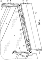
- the tilted position of the bucket is illustrated on the figures 3 and 5 .
- the bucket illustrated in the drawing comprises a bottom 2, a rear door 4, side walls 6 and a front panel 8.
- the bottom 2 is of substantially flat rectangular shape. It is made for example of sheet metal and is fixed on a structure (not shown) giving it good rigidity. Other materials, for example composite materials or any material capable of producing a loading floor, can also be envisaged to form the bottom 2. It will be assumed later that the bottom 2 is in a horizontal plane when the skip is not flipped ( figures 1 , 2 and 4 ).
- the side walls 6, the rear door 4 and the front panel 8 serve to maintain a load placed on the bottom 2.
- the side panels 6 extend longitudinally while the rear door 4 and the front panel 8 extend transversely.
- the various elements, side panels 6, front panel 8, are known to those skilled in the art and therefore will not be described here.
- the mechanism making the tipper is known to those skilled in the art and is not described.
- the following description relates more particularly to the rear door 4.
- the latter can be combined with substantially any type of sideboard, bucket bottom, lifting mechanism, ... known from the prior art. It should be noted that the invention will be described later with reference to a rear door but it could also relate to a sideboard, for example in the case of a bucket that can pivot on the side (for example a bucket of type tri-dump).
- FIGS. 2 to 5 show in more detail the rear door 4 of the body shown on the figure 1 .
- This door comprises a panel 10 and a frame 12.
- the panel 10 is of generally rectangular outer shape. It may have a flat shape but also, as illustrated in the drawing, have shapes that stiffen and / or give an aesthetic appearance.
- the panel 10 is positioned on the figures 1 and 2 .
- For this panel 10 is defined a lower edge 14, an upper edge 16 (free) and two (small) side edges 18.
- the frame 12 has an overall U shape. It thus comprises a base 20 and two lateral branches 22. All these elements (base and branches) are for example made from a metal tube of rectangular section, possibly square , cut and welded to form the frame 12. The dimensions of the frame 12 are adapted to that of the panel 10 (and / or conversely) so that, in the embodiment illustrated in the drawing, the panel 10 can come into place between the side branches 22 resting on the base 20.
- the panel 10 is connected to the base 20 of the frame 12 so as to be pivotable relative to the frame 12.
- the articulation between the panel 10 and the base 20 is at least one and preferably by two hinges 24.
- a tongue 26 is each time fixed (bolted or welded) on the base 20 extending downwards to carry an arm of the hinge 24.
- the panel 10 is pivotally mounted with respect to a pivot axis parallel and close (a few millimeters to a few centimeters apart) from the lower edge 14 of the panel 10.
- the frame 12 is pivotally mounted on the bucket.
- it is provided with first hinge means and the bucket is provided with second articulation means complementary to said first hinge means.
- the first articulation means are formed of two axes which cooperate with bearings forming the second hinge means mounted on the structure of the bucket. In this case, there are thus male elements on the rear door 4 and female elements on the bucket. The opposite is quite possible too.
- the structure of the bucket comprises four posts 28 each arranged at an angle of the bottom 2 and extending vertically upwards.
- the two posts 28 arranged on either side of the rear door 4 are each provided with a double bearing 30, mounted on the upper part of the corresponding poles 28.
- the two double bearings 30 are disposed equidistant from the bottom 2 of the bucket so as to define an axis of articulation parallel to the bottom 2 of the bucket.
- the free ends split to form two substantially parallel arms connected by an axis.
- the two axes (one per side branch 22) are aligned so as to define a hinge axis.
- each axis at one end of a side branch 22 of the frame 12 takes place in a double bearing 30.
- the two arms of the caliper corresponding then come from both sides. of other this double bearing 30.
- a circular lock is guided between the two bearings of the double bearing 30 and can take an open position allowing free access to the housing in the bearings of the double bearing 30 and a closed position which allows to imprison the axis in its housing of the double bearing 30.
- a lever 32 is used to control the circular lock.
- the lever 32 takes place between the arms of the stirrup at the free end of the lateral branches 22.
- Locking means are also associated with the rear door 4. On the one hand, there is a locking of the panel 10 on the frame 12 and, on the other hand, a locking of the frame 12 with respect to the structure of the bucket .
- the locking of the panel 10 is achieved by means of two hooks 34 pivotally mounted on the panel 10.
- the pivot axis is substantially perpendicular to the panel 10, that is to say substantially horizontal.
- the hooks 34 which are associated with a control lever 36, are each facing a branch 22. They are arranged such that in a first pivoted position, the hook 34 is at least partially inside the corresponding lateral branch 22 after passing through a slot 38 made in an inner face of said lateral branch 22 In another position, pivoted with respect to the first position, the hook 34 is fully extended out of the corresponding lateral branch 22.
- the locking of the frame on the structure of the body is realized by latching at least one striker 40 into a closure hook 42.
- a striker 40 (there are two in the illustrated embodiment but only one could also perform the function) is fixed under the base 20 of the frame 12. Each striker 40 is intended to cooperate with a closure hook 42 mounted on the structure of the bucket.
- the closing hook 42 can take a locked position in which it meshes with the striker 40 or take an unlocked position in which it does not mesh with the striker 40.
- the two positions of the closure hook 42 are stable, for example by a spring (not shown) reminding the closing hook in the unlocked position.
- the figure 2 illustrates the rear door 4 in the closed position.
- the panel 10 is locked in its frame 12 and the frame is locked on the bucket.
- the hooks 34 are passed through the slots 38 and are at least partially inside the lateral branches 22 of the frame 12.
- the closing hooks 42 are engaged with the strikers 40. This corresponds for example to a position when the corresponding truck is driving on a road.
- the figure 3 illustrates the bucket in a tilted position. It can be assumed here that the bucket transported for example sand. The sand must be unloaded. An operator then comes to unlock the frame 12 by placing the closing hooks 42 in their unlocked position.
- the hooks used for locking / unlocking can be designed to allow their automatic or mechanical unlocking. As soon as the tilting starts, because of gravity, the back door tends to stay upright. An opening increasing as the slope of the bucket increases appears between the bottom 2 of the bucket and the rear door 4. The sand (or any other material) can then pour through this opening.
- the case illustrated on the figure 5 corresponds to the case of the figure 4 with a tipper.
- a raw material must be dumped.
- the proposed solution makes it possible to have a panel 10 of reduced size, on the one hand, and the axis of rotation of this panel 10 is raised because of the structure of the door compared to a conventional rear door of dumpster.
- the proposed structure is thus compact. Its size is substantially the same as that of a pendulum door or a door opening by folding down while proposing these two modes of opening.
- a rear door as proposed can fit on almost all forms of skips. It can also be implemented for a rear door or for a side wall.
- a rear door, or side, as described above can also be implemented for almost any type of bucket: tipper rearward, tipper laterally, tri-dump, removable bucket, tipper, ... .
- the operation of the door is simple and does not change the habits of a user.
- the locking means described are known to most bucket users which makes the use of the bucket rather intuitive.
Abstract
Porte (4) de benne pendulaire comportant : - un cadre (12) en forme de U avec une base (20) et deux branches latérales (22), - un ouvrant (10) monté articulé pivotant sur la base (20) du cadre (12), et - des moyens de verrouillage (34) de l'ouvrant (10) sur le cadre (12).Door (4) of tipper bucket comprising: a U-shaped frame (12) with a base (20) and two lateral branches (22), - an opening (10) articulated pivotally on the base (20) of the frame (12), and - Locking means (34) of the opening (10) on the frame (12).
Description
La présente invention concerne une porte de benne pendulaire, une benne munie d'une telle porte ainsi qu'un camion avec une telle benne.The present invention relates to a tipper bucket, a bucket provided with such a door and a truck with such a bucket.
Le domaine de la présente invention est celui des véhicules (camions, camionnettes et similaires) munis d'une benne. Cette dernière permet de recevoir tout type de matériel mais aussi des matériaux en vrac (sable, gravier, terre, bois, ...).The field of the present invention is that vehicles (trucks, vans and the like) provided with a bucket. The latter can receive any type of material but also bulk materials (sand, gravel, earth, wood, ...).
Une benne comporte généralement un fond de forme sensiblement plane et le plus souvent globalement rectangulaire. Le fond comporte des rebords sur ses quatre côtés de manière à délimiter un espace de chargement. Certains de ces rebords sont fixes par rapport au fond et un ou plusieurs rebords, appelés alors aussi porte(s), peuvent être mobiles par rapport au fond de manière à faciliter des opérations de déchargement.A bucket generally has a bottom of substantially flat shape and generally generally rectangular. The bottom has flanges on all four sides to define a cargo space. Some of these flanges are fixed relative to the bottom and one or more flanges, also called door (s), can be movable relative to the bottom so as to facilitate unloading operations.
Lorsque des matériaux en vrac sont chargés sur la benne d'un camion (ou similaire), il est connu, d'une part, d'avoir une benne basculante et, d'autre part, d'avoir une porte pendulaire. La benne basculante est munie d'un dispositif de levage qui permet d'incliner le fond de la benne afin de faciliter son déchargement par gravité. Elle est avantageusement combinée à une porte pendulaire qui s'ouvre automatiquement lorsque le fond est incliné. Une telle porte pendulaire est montée pivotante autour d'un axe d'articulation correspondant sensiblement à son bord supérieur de manière à rester à la verticale lorsque la benne bascule. Une ouverture apparait alors entre le fond de la benne et la porte de benne pendulaire. La porte pendulaire se trouve bien entendu au niveau du côté inférieur du fond de la benne lorsque cette dernière est en position inclinée. Ainsi, lorsque la benne bascule, la porte pendulaire s'ouvre, d'une part, sous l'effet de la gravité et, d'autre part, sous l'action de la charge -qui subit également la gravité- qui tend à sortir de la benne.When bulk materials are loaded on the bucket of a truck (or the like), it is known, on the one hand, to have a tipper and, secondly, to have a swing door. The dump body is equipped with a lifting device that allows to tilt the bottom of the bucket to facilitate its unloading by gravity. It is advantageously combined with a swinging door which opens automatically when the bottom is inclined. Such a swinging door is pivotally mounted about an axis of articulation substantially corresponding to its upper edge so as to remain vertical when the bucket tilts. An opening then appears between the bottom of the bucket and the tipping bucket door. The pendulum door is of course at the lower side of the bottom of the bucket when the latter is in an inclined position. Thus, when the bucket tilts, the swing door opens, on the one hand, under the effect of gravity and, on the other hand, under the action of the load-which also undergoes gravity-which tends to get out of the dumpster.
Toutes les bennes ne sont pas munies d'une porte pendulaire. Certaines présentent quatre ridelles fixes. D'autres comportent une ou plusieurs portes qui sont montées articulées selon un axe d'articulation qui correspond sensiblement à leur bord inférieur, c'est-à-dire aussi à l'intersection entre le fond et la porte. Cette porte peut être ouverte lors d'un déchargement pour ne pas avoir à soulever la charge au-dessus du bord supérieur de la porte et faciliter ainsi le déchargement.All skips are not equipped with a swinging door. Some have four fixed sides. Others comprise one or more doors which are mounted articulated along a hinge axis which substantially corresponds to their lower edge, that is to say also to the intersection between the bottom and the door. This door can be opened during unloading so as not to have to lift the load above the top edge of the door and thus facilitate unloading.
Le document
Le document
Le document
Enfin, le document
L'idée à l'origine de la présente invention est d'avoir une porte de benne qui puisse s'ouvrir soit en mode automatique (pendulaire) comme expliqué plus haut pour le déchargement de matériau en vrac, soit en mode manuel en pivotant autour d'un axe d'articulation inférieur, cette porte pouvant s'adapter à des bennes sans adaptation particulière de la benne.The idea behind the present invention is to have a dump door which can open either in automatic mode (pendulum) as explained above for the unloading of bulk material, or in manual mode by pivoting around a lower hinge pin, this door can be adapted to skips without special adaptation of the bucket.
La présente invention a alors pour but de fournir une porte de benne pendulaire qui puisse aussi s'ouvrir en s'articulant autour d'un axe inférieur, comme une ridelle mobile et ce sans que la structure de cette porte à double ouverture ne vienne dégrader le fonctionnement dans l'un ou l'autre mode. Il convient donc d'un côté que la porte selon l'invention permette un fonctionnement en porte pendulaire comme une porte pendulaire sans créer d'obstacle au déversement du contenu d'une benne et d'un autre côté que le fonctionnement en pivotant autour d'un axe d'articulation inférieur.The purpose of the present invention is therefore to provide a pendular bucket door that can also be opened by articulating around a lower axis, such as a mobile sidewall, without the structure of this double-opening door degrading. operation in one or the other mode. It is therefore appropriate on one side that the door according to the invention allows a pendulum door operation as a swing door without creating an obstacle to the discharge of the contents of a bucket and on the other side that the operation by pivoting around a lower hinge pin.
Un but de la présente invention est d'obtenir une structure de porte compacte, qui est avantageusement facile à utiliser.An object of the present invention is to obtain a compact door structure, which is advantageously easy to use.
À cet effet, la présente invention propose une porte de benne pendulaire, caractérisée en ce qu'elle comporte :
- un cadre en forme de U avec une base et deux branches latérales,
- un ouvrant monté articulé pivotant sur la base du cadre, et
- des moyens de verrouillage de l'ouvrant sur le cadre.
- a U-shaped frame with a base and two side branches,
- an articulated hinged opening pivoting on the base of the frame, and
- locking means of the opening on the frame.
Cette forme de réalisation originale permet d'obtenir une porte s'ouvrant de façon pendulaire ou bien en se rabattant vers le bas. On entend ici par porte un élément destiné à prendre place dans un bâti et mobile entre une première position dans laquelle ledit élément constitue un dispositif de fermeture d'un passage et au moins une autre position dans laquelle le passage est libéré.This original embodiment makes it possible to obtain a door opening in a pendular manner or by folding downwards. Door here means an element intended to take place in a frame and movable between a first position in which said element constitutes a closure device of a passage and at least one other position in which the passage is released.
Comme il s'agit d'une porte pendulaire, elle est naturellement munie de premiers moyens d'articulation destinés à coopérer avec des seconds moyens d'articulation prenant place sur le « bâti » recevant la porte. Cette articulation se fera autour d'un axe sensiblement horizontal. Habituellement, les moyens d'articulation comportent deux charnières avec chacune une partie mâle, ou axe, et une partie femelle, palier ou noeud. La porte selon l'invention comporte alors de préférence soit deux parties mâles, soit deux parties femelles. Ces éléments d'articulation viennent prendre place sur les branches latérales du cadre, de préférence au niveau de l'extrémité libre de chacune de ces branches.As it is a pendulum door, it is naturally provided with first hinge means for cooperating with second hinge means taking place on the "frame" receiving the door. This articulation will be around a substantially horizontal axis. Usually, the hinge means comprise two hinges each with a male part, or axis, and a female part, bearing or knot. The door according to the invention then preferably comprises either two male parts or two female parts. These hinge elements take place on the lateral branches of the frame, preferably at the free end of each of these branches.
Selon une forme de réalisation, le cadre d'une porte selon la présente invention est un cadre tubulaire.According to one embodiment, the frame of a door according to the present invention is a tubular frame.
Pour réaliser l'articulation de l'ouvrant sur la base du cadre, on peut utiliser par exemple au moins une, et de préférence deux, charnière(s).To achieve the articulation of the opening on the base of the frame, can be used for example at least one, and preferably two, hinge (s).
On peut prévoir que les moyens de verrouillage comportent au moins un crochet monté pivotant sur l'ouvrant et coopérant avec un contre-crochet sur le cadre, l'axe de pivotement du crochet étant perpendiculaire à l'ouvrant. Dans cette forme de réalisation, lorsque le cadre présent une structure tubulaire, on peut avantageusement envisager le contre-crochet soit une fente réalisée dans une face d'une branche latérale du cadre.It can be provided that the locking means comprise at least one hook pivotally mounted on the opening and cooperating with a counter-hook on the frame, the pivot axis of the hook being perpendicular to the opening. In this embodiment, when the frame has a tubular structure, it is advantageous to consider the counter-hook is a slot made in a side of a side branch of the frame.
Pour réaliser un verrouillage du cadre sur la structure d'une benne, on peut prévoir que la base du cadre comporte au moins une gâche sur une face extérieure, c'est-à-dire opposée aux branches latérales.To achieve a frame lock on the structure of a bucket, it can be provided that the base of the frame comprises at least one striker on an outer face, that is to say opposite to the side branches.
Pour réaliser la liaison de la porte de benne pendulaire avec une structure de benne, on peut avantageusement prévoir que les extrémités libres des branches latérales présentent chacune une forme d'étrier avec deux bras reliés entre eux par un axe. L'axe peut alors venir prendre place dans un palier monté sur la structure de ladite benne.To achieve the connection of the tipping bucket door with a bucket structure, it is advantageous that the free ends of the side branches each have a stirrup shape with two arms interconnected by an axis. The axis can then take place in a bearing mounted on the structure of said bucket.
La présente invention concerne également :
- une benne, par exemple benne basculante, caractérisée en ce qu'elle comporte une porte de benne pendulaire telle que décrite précédemment. Une telle benne peut comporter un fond de forme rectangulaire, deux poteaux s'étendant perpendiculairement au fond à deux angles voisins du fond, et lesdits montants portent alors avantageusement des moyens d'articulation complémentaires des moyens définissant un axe d'articulation pour le cadre de la porte de benne pendulaire
- a bucket, for example tipper, characterized in that it comprises a tilting bucket door as described above. Such a bucket may comprise a bottom of rectangular shape, two posts extending perpendicular to the bottom at two adjacent corners of the bottom, and said uprights then advantageously carry means of articulation complementary means defining a hinge axis for the frame of the tipper bucket
La présente invention concerne alors aussi :
- un véhicule motorisé (camion, camionnette, "pick-up", ...), caractérisé en ce qu'il comporte une benne selon l'alinéa précédent, et
- un véhicule tracté, notamment remorque, caractérisé en ce qu'il comporte une benne telle que définie ci-dessus.
- a motorized vehicle (truck, van, "pick-up", ...), characterized in that it comprises a bucket according to the preceding paragraph, and
- a towed vehicle, particularly trailer, characterized in that it comprises a bucket as defined above.
Des détails et avantages de la présente invention apparaitront mieux de la description qui suit, faite en référence au dessin schématique annexé sur lequel :
- La
figure 1 illustre une benne de camion selon l'invention, - La
figure 2 est une vue montrant à plus grande échelle la porte arrière de la benne de lafigure 1 , - La
figure 3 est une vue correspondant à lafigure 2 selon un premier mode d'ouverture, - La
figure 4 est une vue correspondant auxfigures 2 et3 selon un autre mode d'ouverture, et - La
figure 5 est une vue correspondant à lafigure 4 , la benne étant en outre basculée.
- The
figure 1 illustrates a truck body according to the invention, - The
figure 2 is a view showing on a larger scale the back door of the bucket of thefigure 1 , - The
figure 3 is a view corresponding to thefigure 2 according to a first mode of opening, - The
figure 4 is a view corresponding tofigures 2 and3 according to another mode of opening, and - The
figure 5 is a view corresponding to thefigure 4 , the bucket being further tilted.
D'un premier abord, la benne illustrée sur la
De manière classique, la benne illustrée au dessin comporte un fond 2, une porte arrière 4, des ridelles latérales 6 et un panneau avant 8.Conventionally, the bucket illustrated in the drawing comprises a
Le fond 2 est de forme rectangulaire sensiblement plane. Il est réalisé par exemple en tôle et est fixé sur une structure (non représentée) lui donnant une bonne rigidité. D'autres matériaux, par exemple des matériaux composites ou tout matériau apte à réaliser un plancher de chargement, peuvent aussi être envisagés pour former le fond 2. On supposera par la suite que le fond 2 est dans un plan horizontal lorsque la benne n'est pas basculée (
Les ridelles latérales 6, la porte arrière 4 et le panneau avant 8 servent à maintenir une charge posée sur le fond 2. Par rapport au sens de roulement du camion sur lequel la benne est destinée à être montée, les ridelles latérales 6 s'étendent longitudinalement tandis que la porte arrière 4 et le panneau avant 8 s'étendent transversalement. Les différents éléments, ridelles latérales 6, panneau avant 8, sont connus de l'homme du métier et ne seront donc pas décrits ici. De même, le mécanisme rendant la benne basculante est connu de l'homme du métier et n'est pas décrit. La description qui suit concerne plus particulièrement la porte arrière 4. Cette dernière peut être combinée à sensiblement tout type de ridelle latérale, de fond de benne, de mécanisme de levage, ... connus de l'art antérieur. Il est à noter que l'invention va être décrite plus loin en référence à une porte arrière mais qu'elle pourrait aussi concerner une ridelle latérale, par exemple dans le cas d'une benne pouvant pivoter sur le côté (par exemple une benne de type tri-benne).The
Les
Le panneau 10 est de forme extérieure globalement rectangulaire. Il peut avoir une forme plane mais aussi, comme illustré sur le dessin, présenter des formes qui le rigidifient et/ou qui donnent un aspect esthétique.The
On supposera par la suite le panneau 10 comme positionné sur les
Le cadre 12 présente quant à lui une forme globale en U. Il comporte ainsi une base 20 et deux branches latérales 22. Tous ces éléments (base et branches) sont par exemple réalisés à partir d'un tube métallique de section rectangulaire, éventuellement carrée, coupé et soudé pour former le cadre 12. Les dimensions du cadre 12 sont adaptées à celle du panneau 10 (et/ou inversement) de telle sorte que, dans la forme de réalisation illustrée sur le dessin, le panneau 10 puisse venir prendre place entre les branches latérales 22 en reposant sur la base 20.The
Le panneau 10 est relié à la base 20 du cadre 12 de manière à pouvoir pivoter par rapport au cadre 12. Dans la forme de réalisation illustrée, l'articulation entre le panneau 10 et la base 20 se fait au moins une et de préférence par deux charnières 24. Pour pouvoir avoir un cadre 12 fin (et léger), une languette 26 est à chaque fois fixée (boulonnée ou soudée) sur la base 20 en s'étendant vers le bas pour porter un bras de la charnière 24. Ainsi le panneau 10 est monté pivotant par rapport à un axe de pivotement parallèle et proche (distant de quelques millimètres à quelques centimètres) du bord inférieur 14 du panneau 10.The
Le cadre 12 est quant à lui monté pivotant sur la benne. À cet effet, il est muni de premiers moyens d'articulation et la benne est munie quant à elle de seconds moyens d'articulation complémentaires auxdits premiers moyens d'articulation. Ici, dans la forme de réalisation illustrée, les premiers moyens d'articulation sont formés de deux axes qui viennent coopérer avec des paliers formant les seconds moyens d'articulation montés sur la structure de la benne. Dans ce cas de figure, on a ainsi des éléments mâles sur la porte arrière 4 et des éléments femelles sur la benne. L'inverse est tout à fait envisageable également.The
Comme on peut mieux le voir sur la
Pour le montage de la porte arrière 4 sur la benne, les deux poteaux 28 disposés de part et d'autre de la porte arrière 4 sont chacun munis d'un palier double 30, monté sur la partie haute des poteaux 28 correspondants. Les deux paliers doubles 30 sont disposés à égale distance du fond 2 de la benne de manière à définir un axe d'articulation parallèle au fond 2 de la benne.For the mounting of the
Les extrémités libres des branches latérales 22 du cadre 12, c'est-à-dire les extrémités de ces branches latérales 22 opposées à la base 20, portent les premiers moyens d'articulation qui se présentent sous la forme d'un étrier (renversé). Les extrémités libres se dédoublent pour former deux bras sensiblement parallèles reliés par un axe. Les deux axes (un par branche latérale 22) sont alignés de manière à définir un axe d'articulation.The free ends of the
Pour le montage de la porte arrière 4 sur la benne, chaque axe se trouvant à une extrémité d'une branche latérale 22 du cadre 12 vient prendre place dans un palier double 30. Les deux bras de l'étrier correspondant viennent alors de part et d'autre de ce palier double 30. Pour sécuriser l'axe de l'étrier dans le palier double 30, un verrou circulaire est guidé entre les deux paliers du palier double 30 et peut prendre une position ouverte laissant libre accès au logement dans les paliers du palier double 30 ainsi qu'une position fermée qui permet d'emprisonner l'axe dans ses logements du palier double 30. Un levier 32 est utilisé pour commander le verrou circulaire. Avantageusement, il sera prévu que lorsque le verrou circulaire est dans sa position verrouillée, le levier 32 vient prendre place entre les bras de l'étrier se trouvant à l'extrémité libre des branches latérales 22.For the mounting of the
Des moyens de verrouillage sont aussi associés à la porte arrière 4. On trouve, d'une part, un verrouillage du panneau 10 sur le cadre 12 et, d'autre part, un verrouillage du cadre 12 par rapport à la structure de la benne.Locking means are also associated with the
Le verrouillage du panneau 10 est réalisé à l'aide de deux crochets 34 montés pivotants sur le panneau 10. L'axe de pivotement est sensiblement perpendiculaire au panneau 10, c'est-à-dire sensiblement horizontal. En position fermée du panneau 10, c'est-à-dire que le panneau se trouve entre les deux branches latérales 22 du cadre 12, les crochets 34, qui sont associés à un levier de commande 36, se trouvent chacun face à une branche latérale 22. Ils sont disposés de telle sorte que dans une première position pivotée, le crochet 34 est au moins partiellement à l'intérieur de la branche latérale 22 correspondante après être passé dans une fente 38 réalisée dans une face intérieure de ladite branche latérale 22. Dans une autre position, pivotée par rapport à la première position, le crochet 34 est entièrement sorti hors de la branche latérale 22 correspondante.The locking of the
Le verrouillage du cadre sur la structure de la benne est réalisé par encliquetage d'au moins une gâche 40 dans un crochet de fermeture 42.The locking of the frame on the structure of the body is realized by latching at least one
Comme visible notamment sur la
La
La
Dans le cas de la
Le cas de figure illustré sur la
La porte arrière décrite ci-dessus, ainsi que la benne intégrant une telle porte, présentent plusieurs avantages.The rear door described above, and the bucket incorporating such a door, have several advantages.
La structure proposée est ainsi compacte. Son encombrement est sensiblement le même que celui d'une porte pendulaire ou qu'une porte s'ouvrant en se rabattant vers le bas tout en proposant ces deux modes d'ouverture.The proposed structure is thus compact. Its size is substantially the same as that of a pendulum door or a door opening by folding down while proposing these two modes of opening.
Une porte -arrière- telle que proposée peut s'adapter sur quasiment toutes les formes de bennes. Elle peut en outre être mise en oeuvre pour une porte arrière ou bien pour une ridelle latérale.A rear door as proposed can fit on almost all forms of skips. It can also be implemented for a rear door or for a side wall.
Une porte arrière, ou latérale, telle que décrite ci-dessus peut aussi être mise en oeuvre pour quasiment tout type de benne : benne basculant vers l'arrière, benne basculant latéralement, tri-benne, benne amovible, benne déposable, ....A rear door, or side, as described above can also be implemented for almost any type of bucket: tipper rearward, tipper laterally, tri-dump, removable bucket, tipper, ... .
Le fonctionnement de la porte est simple et ne change pas les habitudes d'un utilisateur. Les moyens de verrouillage décrits sont connus de la plupart des utilisateurs de benne ce qui rend l'utilisation de la benne plutôt intuitif.The operation of the door is simple and does not change the habits of a user. The locking means described are known to most bucket users which makes the use of the bucket rather intuitive.
Bien entendu, la présente invention ne se limite pas à la forme de réalisation préférée décrite ci-dessus en référence au dessin schématique annexé et aux variantes évoquées mais concerne également les autres formes de réalisation à la portée de l'homme du métier dans le cadre des revendications ci-après.Of course, the present invention is not limited to the preferred embodiment described above with reference to the attached schematic drawing and the variants mentioned but also relates to other embodiments within the reach of the skilled person in the context of the claims below.
Claims (13)
Applications Claiming Priority (1)
| Application Number | Priority Date | Filing Date | Title |
|---|---|---|---|
| FR1656866A FR3054178B1 (en) | 2016-07-19 | 2016-07-19 | PENDULUM BUCKET DOOR |
Publications (1)
| Publication Number | Publication Date |
|---|---|
| EP3272579A1 true EP3272579A1 (en) | 2018-01-24 |
Family
ID=57045145
Family Applications (1)
| Application Number | Title | Priority Date | Filing Date |
|---|---|---|---|
| EP17181190.4A Withdrawn EP3272579A1 (en) | 2016-07-19 | 2017-07-13 | Pendulum tailgate for container |
Country Status (2)
| Country | Link |
|---|---|
| EP (1) | EP3272579A1 (en) |
| FR (1) | FR3054178B1 (en) |
Families Citing this family (1)
| Publication number | Priority date | Publication date | Assignee | Title |
|---|---|---|---|---|
| JP6913863B2 (en) * | 2019-03-28 | 2021-08-04 | 路人 増永 | container |
Citations (5)
| Publication number | Priority date | Publication date | Assignee | Title |
|---|---|---|---|---|
| US2260504A (en) * | 1940-08-08 | 1941-10-28 | Gar Wood Ind Inc | Counterbalanced tail gate |
| DE1890897U (en) | 1963-12-12 | 1964-04-09 | Eberhard Prange | DEVICE FOR LOCKING AND UNLOCKING THE REAR LOCKING FLAP OF AT LEAST IN THE LONGITUDINAL DIRECTION OF TIPPING BOTTOMS OF TRUCKS. |
| US3230014A (en) | 1964-05-27 | 1966-01-18 | Victor E Mutti | Automatic tail gate opening means for trucks |
| JPS58211928A (en) | 1982-06-04 | 1983-12-09 | Tokyu Car Corp | Packing-box lifting apparatus equipped with tail-gate lifter |
| WO1993003949A1 (en) | 1991-08-20 | 1993-03-04 | Bemuro Utveckling Ab | Lock, especially for platform sides on vehicles |
-
2016
- 2016-07-19 FR FR1656866A patent/FR3054178B1/en active Active
-
2017
- 2017-07-13 EP EP17181190.4A patent/EP3272579A1/en not_active Withdrawn
Patent Citations (5)
| Publication number | Priority date | Publication date | Assignee | Title |
|---|---|---|---|---|
| US2260504A (en) * | 1940-08-08 | 1941-10-28 | Gar Wood Ind Inc | Counterbalanced tail gate |
| DE1890897U (en) | 1963-12-12 | 1964-04-09 | Eberhard Prange | DEVICE FOR LOCKING AND UNLOCKING THE REAR LOCKING FLAP OF AT LEAST IN THE LONGITUDINAL DIRECTION OF TIPPING BOTTOMS OF TRUCKS. |
| US3230014A (en) | 1964-05-27 | 1966-01-18 | Victor E Mutti | Automatic tail gate opening means for trucks |
| JPS58211928A (en) | 1982-06-04 | 1983-12-09 | Tokyu Car Corp | Packing-box lifting apparatus equipped with tail-gate lifter |
| WO1993003949A1 (en) | 1991-08-20 | 1993-03-04 | Bemuro Utveckling Ab | Lock, especially for platform sides on vehicles |
Also Published As
| Publication number | Publication date |
|---|---|
| FR3054178B1 (en) | 2020-12-25 |
| FR3054178A1 (en) | 2018-01-26 |
Similar Documents
| Publication | Publication Date | Title |
|---|---|---|
| EP1215107B1 (en) | Motor car with extensible loading platform | |
| WO2001017880A1 (en) | Device for locking/unlocking, by gravity, the lid of a container and container equipped therewith | |
| FR2859675A1 (en) | CARRIER CARRIER HAVING A LATERAL OPENING OF THE CHASSIS EQUIPPED WITH A DOUBLE HINGED DOOR | |
| EP1706284B1 (en) | Closing device for a vehicle provided with a hatch and a sunroof | |
| EP1698513A1 (en) | Exchangeable container, with integrated ladder, for storing and transporting material | |
| EP1412213B1 (en) | Convertible vehicle with retractable roof | |
| FR2735430A1 (en) | TIPPER AND VEHICLE COMPRISING THE SAME | |
| EP3272579A1 (en) | Pendulum tailgate for container | |
| EP1885627A2 (en) | Cover device for an open carrier, container or a trailer | |
| CA2891969C (en) | Rubbish collection vehicle with an improved container lifter | |
| FR2885571A1 (en) | Movable luggage compartment floor for use in motor vehicle, has side liners, each including cam paths cooperating with lateral projections, and locking unit cooperating with complementary locking unit of plate | |
| EP2927160B1 (en) | All-door construction skip comprising a retractable control spreader and having reduced width | |
| FR2944488A1 (en) | Autonomous loading bed for e.g. trailer, has pushing units pushing raising wall between loading position in which lower edge rests on bottom and unloading position in which lower edge is remote from bottom, and raises and pushes back load | |
| WO2005080107A1 (en) | Vehicle comprising a sunroof and a hatch | |
| EP1707437B1 (en) | System for unlocking the tailgate of a dump bucket | |
| EP3476768B1 (en) | Waste collecting and emptying system | |
| EP3090927A1 (en) | Transport structure provided with a vertically sliding door | |
| FR3037010A1 (en) | RECOVERABLE SEAT PROVIDED WITH TRAINING MEANS ARRANGED BETWEEN THE SEAT AND THE BACKREST AND MOTOR VEHICLE COMPRISING SUCH A SEAT | |
| FR2837806A1 (en) | Folding roof for e.g. trailer comprises hinged panels with rollers on their edges which move on rails mounted inside frame on rim of trailer, locking system allowing panels to be opened in either direction | |
| EP2221231B1 (en) | Transport assembly comprising a trolley and at least two adapted containers | |
| FR2944512A1 (en) | Case for trailer body of truck to transport and/or store loads i.e. bulk materials, has movable side member comprising concavity turned towards interior to direct masses loaded in direction of base wall in closed position | |
| EP1512580B1 (en) | Baggage cover | |
| WO2008065292A1 (en) | Convertible three-volume motor vehicle | |
| WO1997012698A1 (en) | Device for recovering the component material of the window in a motor vehicle door such as a rear hatch | |
| FR2677338A1 (en) | Vehicle for the selective collection of waste, particularly domestic waste |
Legal Events
| Date | Code | Title | Description |
|---|---|---|---|
| PUAI | Public reference made under article 153(3) epc to a published international application that has entered the european phase |
Free format text: ORIGINAL CODE: 0009012 |
|
| AK | Designated contracting states |
Kind code of ref document: A1 Designated state(s): AL AT BE BG CH CY CZ DE DK EE ES FI FR GB GR HR HU IE IS IT LI LT LU LV MC MK MT NL NO PL PT RO RS SE SI SK SM TR |
|
| AX | Request for extension of the european patent |
Extension state: BA ME |
|
| 17P | Request for examination filed |
Effective date: 20180716 |
|
| RBV | Designated contracting states (corrected) |
Designated state(s): AL AT BE BG CH CY CZ DE DK EE ES FI FR GB GR HR HU IE IS IT LI LT LU LV MC MK MT NL NO PL PT RO RS SE SI SK SM TR |
|
| 17Q | First examination report despatched |
Effective date: 20200305 |
|
| STAA | Information on the status of an ep patent application or granted ep patent |
Free format text: STATUS: THE APPLICATION IS DEEMED TO BE WITHDRAWN |
|
| 18D | Application deemed to be withdrawn |
Effective date: 20200716 |