EP3272450B1 - Method of and system for welding with a torch, a temperature detector and a controller - Google Patents
Method of and system for welding with a torch, a temperature detector and a controller Download PDFInfo
- Publication number
- EP3272450B1 EP3272450B1 EP17001193.6A EP17001193A EP3272450B1 EP 3272450 B1 EP3272450 B1 EP 3272450B1 EP 17001193 A EP17001193 A EP 17001193A EP 3272450 B1 EP3272450 B1 EP 3272450B1
- Authority
- EP
- European Patent Office
- Prior art keywords
- temperature
- workpiece
- welding
- arc
- tolerance
- Prior art date
- Legal status (The legal status is an assumption and is not a legal conclusion. Google has not performed a legal analysis and makes no representation as to the accuracy of the status listed.)
- Active
Links
Images


Classifications
-
- B—PERFORMING OPERATIONS; TRANSPORTING
- B23—MACHINE TOOLS; METAL-WORKING NOT OTHERWISE PROVIDED FOR
- B23K—SOLDERING OR UNSOLDERING; WELDING; CLADDING OR PLATING BY SOLDERING OR WELDING; CUTTING BY APPLYING HEAT LOCALLY, e.g. FLAME CUTTING; WORKING BY LASER BEAM
- B23K9/00—Arc welding or cutting
- B23K9/095—Monitoring or automatic control of welding parameters
- B23K9/0956—Monitoring or automatic control of welding parameters using sensing means, e.g. optical
-
- B—PERFORMING OPERATIONS; TRANSPORTING
- B23—MACHINE TOOLS; METAL-WORKING NOT OTHERWISE PROVIDED FOR
- B23K—SOLDERING OR UNSOLDERING; WELDING; CLADDING OR PLATING BY SOLDERING OR WELDING; CUTTING BY APPLYING HEAT LOCALLY, e.g. FLAME CUTTING; WORKING BY LASER BEAM
- B23K9/00—Arc welding or cutting
- B23K9/095—Monitoring or automatic control of welding parameters
- B23K9/0953—Monitoring or automatic control of welding parameters using computing means
-
- B—PERFORMING OPERATIONS; TRANSPORTING
- B23—MACHINE TOOLS; METAL-WORKING NOT OTHERWISE PROVIDED FOR
- B23K—SOLDERING OR UNSOLDERING; WELDING; CLADDING OR PLATING BY SOLDERING OR WELDING; CUTTING BY APPLYING HEAT LOCALLY, e.g. FLAME CUTTING; WORKING BY LASER BEAM
- B23K9/00—Arc welding or cutting
- B23K9/12—Automatic feeding or moving of electrodes or work for spot or seam welding or cutting
- B23K9/124—Circuits or methods for feeding welding wire
- B23K9/125—Feeding of electrodes
-
- B—PERFORMING OPERATIONS; TRANSPORTING
- B23—MACHINE TOOLS; METAL-WORKING NOT OTHERWISE PROVIDED FOR
- B23K—SOLDERING OR UNSOLDERING; WELDING; CLADDING OR PLATING BY SOLDERING OR WELDING; CUTTING BY APPLYING HEAT LOCALLY, e.g. FLAME CUTTING; WORKING BY LASER BEAM
- B23K9/00—Arc welding or cutting
- B23K9/12—Automatic feeding or moving of electrodes or work for spot or seam welding or cutting
- B23K9/127—Means for tracking lines during arc welding or cutting
-
- B—PERFORMING OPERATIONS; TRANSPORTING
- B23—MACHINE TOOLS; METAL-WORKING NOT OTHERWISE PROVIDED FOR
- B23K—SOLDERING OR UNSOLDERING; WELDING; CLADDING OR PLATING BY SOLDERING OR WELDING; CUTTING BY APPLYING HEAT LOCALLY, e.g. FLAME CUTTING; WORKING BY LASER BEAM
- B23K9/00—Arc welding or cutting
- B23K9/16—Arc welding or cutting making use of shielding gas
- B23K9/173—Arc welding or cutting making use of shielding gas and of a consumable electrode
-
- B—PERFORMING OPERATIONS; TRANSPORTING
- B23—MACHINE TOOLS; METAL-WORKING NOT OTHERWISE PROVIDED FOR
- B23K—SOLDERING OR UNSOLDERING; WELDING; CLADDING OR PLATING BY SOLDERING OR WELDING; CUTTING BY APPLYING HEAT LOCALLY, e.g. FLAME CUTTING; WORKING BY LASER BEAM
- B23K9/00—Arc welding or cutting
- B23K9/23—Arc welding or cutting taking account of the properties of the materials to be welded
Definitions
- the present invention relates to a welding system and a method of using a welding system according to the preamble of claims 1 and 11 (see for example US2013/264322 A1 ), with controlling of a heat input for a weld or metal deposition process by monitoring a temperature of a workpiece at a location a distance from the arc and parallel to a direction of travel of a torch.
- Heat input into a weld is an important consideration. Often a maximum heat input level is determined and then the appropriate welding waveform and parameters are selected for the weld. However, it is difficult to change these parameters or the heat input during welding. Accordingly, an improved welding methodology and/or system addressing these concerns is needed.
- a welding system is defined in claim 1.
- Embodiments of the invention relate to methods and systems that relate to semi-automatic or manual welding and detecting a base material (e.g., workpiece) temperature, communicating the base material temperature, and adjusting the welding operation based on the detected base material temperature.
- a temperature sensor detects temperature at a location that is a distance from the arc and, for instance, parallel to a direction of travel of the welding torch and such detected temperature can be communicated to the user performing the weld or the user controlling the semi-automatic welding system. The user is informed if the detected temperature is within a tolerance or approved range or if the detected temperature is outside the tolerance or approved range for the type of base material and/or pre-defined temperature.
- Each base material or workpiece can have a corresponding temperature and distance from the center of the arc created that should be maintained for a quality weld. For instance, upon notification or indication of the detected temperature being outside a tolerance, the user can adjust a travel speed or a wire feed speed to compensate for the temperature of the base material cooling too quickly or too slowly.
- the detected temperature or the indication can be communicated to the user via a feedback device that provides communication such as, but not limited to, auditory, visual, adaptive, haptic, among others.
- the feedback device can be, but is not limited to, a helmet, gloves, an electronic device, a wearable electronic device, or an apron.
- the indication can be a green light for within tolerance and a red light for outside tolerance, and such light can be flashed in a peripheral vision of the user via the helmet or welding lens of a helmet.
- “Welding” or “weld” as used herein including any other formatives of these words will refer to depositing of molten material through the operation of an electric arc including but not limited to submerged arc, GTAW, GMAW, MAG, MIG, TIG welding, any high energy heat source (e.g., a laser, an electron beam, among others), or any electric arc used with a welding system.
- the welding operation can be on a workpiece that includes a coating such as, but not limited to, a galvanized coating.
- Component as used herein can be a portion of hardware, a portion of software, or a combination thereof that can include or utilize at least a processor and a portion of memory, wherein the memory includes an instruction to execute.
- tolerance as used herein including any other formatives of the word will refer to an allowable amount of variation of a specified quantity for a value.
- a tolerance can be defined (e.g., dynamically, predefined, among others) for temperature for a given location for a type of workpiece for a type of welding operation. It is to be appreciated that the tolerance can be chosen with sound engineering judgment and/or by one of ordinary skill in the art without departing from the scope of the subject innovation.
- Figs. 1-5 illustrates a welding system that is used with an automated or semi-automated welding system.
- a welding system 100 is illustrated that reduces inconsistencies in heat input based on a measured temperature of a workpiece at a distance adjacent to a travel path of the welding torch.
- System 100 includes welding torch 110 (also referred to as "torch") having an electrode in which power source 104 creates arc 112 between electrode and workpiece W to complete an electrical circuit to perform the welding operation.
- System 100 can include power source 104 that is configured to create arc 112 between an electrode and workpiece W and further include wire feeder 106 is configured to deliver welding wire to a puddle formed by the electrode.
- Controller 102 can be configured to manage wire feed speed (WFS) of wire feeder 106 , power source 104 that creates arc 112 for the welding operation.
- WFS wire feed speed
- the system 100 can be used to perform a welding operation with a consumable electrode, a non-consumable electrode, a shielding gas, no shielding gas, or a combination thereof.
- Heat input for a welding operation can be a critical factor for a weld created but also a workpiece W after a weld has been created on such workpiece W.
- some applications or industries require consistent heat input along a length of a weld in order to avoid inconsistencies in a weld created, on the workpiece W, and/or in a composition of the workpiece W.
- a defect can emerge by cooling too fast causing internal cracking for workpiece W, internal stress for workpiece W, and/or harden workpiece W. Further, defects may emerge for inconsistent heat input by cooling too slow causing increased pores in workpiece W.
- System 100 allows for increasing consistency in a weld as well as workpiece W after a weld has been created.
- System 100 further includes temperature sensor 108 that is configured to detect a temperature at a location or a path that is adjacent to a travel path of the welding operation. By detecting or measuring a temperature at a location or a path adjacent to a travel path of the welding operation, system 100 can determine heat input for a weld created as well as for workpiece W. In particular, measuring a temperature at a location on the arc or at the arc is problematic due to the intense heat input as well as variables surrounding such location.
- system 100 measures temperature at a location that is a distance away from the arc in which such distance has a tolerance for a temperature dependent upon at least one of a type of material for workpiece W, a location of where the temperature is being measured, a type of welding operation being performed, a welding parameter, among others.
- temperature sensor 108 detects temperature at a location in which controller 102 generates an indication if the temperature detected exceeds a tolerance.
- Temperature sensor 108 measures a temperature of a workpiece W at a location on workpiece W.
- the location on workpiece W can be adjacent to at least one of arc 112, welding torch 110, electrode, a weld created, a travel path of electrode, a travel path of torch head 110, a pre-defined path for an anticipated weld to be created, or a combination thereof.
- temperature sensor 108 is according to the present invention configured to identify a temperature of workpiece W during a welding operation.
- temperature sensor 108 can be configured to identify a temperature of workpiece W at a time, wherein the time can be, but is not limited to being, before a welding operation, during a welding operation, after a welding operation, or a combination thereof.
- controller 102 is according to the present invention configured to communicate an indication when a tolerance is exceeded for a temperature at a location, wherein the tolerance is according to the present invention based on at least one of a time a temperature is obtained, a type of material of workpiece W, a type of welding operation, a type of electrode (e.g., consumable, non-consumable, composition of electrode, among others), a welding parameter, a distance from a location, a location on the workpiece, among others, or a combination thereof.
- a tolerance is exceeded for a temperature at a location
- the tolerance is according to the present invention based on at least one of a time a temperature is obtained, a type of material of workpiece W, a type of welding operation, a type of electrode (e.g., consumable, non-consumable, composition of electrode, among others), a welding parameter, a distance from a location, a location on the workpiece, among others, or a combination thereof.
- Temperature sensor 108 is configured to measure, detect, or identify a temperature of workpiece W.
- Temperature sensor 108 can be, but is not limited to being, an infrared temperature device, a thermography device, a thermal camera, a thermocouple, a thermistor, a resistance temperature detector (RTD), a remote sensor, a wireless sensor, a wireless device, a transmission and reception system with a temperature sensor, a pyrometer, a Langmuir probe, a thermometer, one or more devices that communicate temperature information or data for a location, among others.
- temperature sensor 108 is depicted as a stand-alone sensor, temperature sensor 108 or a portion of the temperature sensor 108 can be incorporated into at least one of controller 102, torch head 110, wire feeder 106, power source 104, workpiece W, electrode, or a combination thereof.
- temperature sensor 108 can include a temperature sensor system in which the temperature sensor obtains temperature data, the temperature data is communicated to a component, wherein the component can be controller 102 or a component that communicates the temperature data to controller 102. It is to be appreciated that such communication of temperature data from temperature sensor 108 can be wired, wireless, or via one or more components (e.g., transmitter, receiver, among others).
- Temperature sensor 108 detects an actual temperature of workpiece W , wherein such detection can be at or on a location of the workpiece W. It is to be appreciated that system 100 can include one or more temperature sensors 108 which measure temperatures at one or more locations of workpiece W.
- Controller 102 can be configured to communicate an indication when a temperature measured, detected, or obtained, exceeds a tolerance for the welding operation.
- the tolerance can be determined based on at least one of a time a temperature is obtained, a type of material of workpiece W, a type of welding operation, a type of electrode (e.g., consumable, non-consumable, composition of electrode, among others), a welding parameter, a distance from a location, a location on the workpiece, among others, or a combination thereof.
- the indication can be, but is not limited to being, audible, haptic feedback, visual, electronic communication (e.g., text message, electronic mail, displayed text, telephone communication, cellular communication, among others), or a combination thereof.
- controller 102 can adjust a welding parameter based on the detected temperature exceeding a threshold.
- the indication can be to an operator performing the welding operation to adjust a travel speed of the welding torch 110. For instance, for a tolerance that is exceeded due to a detected temperature above a maximum temperature for the welding operation, the indication can be to increase travel speed. In another instance, for a tolerance that is exceeded due to a detected temperature below a minimum temperature for the welding operation, the indication can be to decrease travel speed.
- controller 102 or operator performing the welding operation can adjust a wire feed speed via wire feeder 106, wherein the adjustment is based on the communicated indication.
- the indication can be to decrease wire feed speed.
- the indication can be to increase wire feed speed.
- the welding parameter can be, a type of welding operation, a type of shielding gas, a material composition of workpiece W , a welding pattern, a type of electrode, a composition of electrode, a wire feed speed, a waveform used for the welding operation, a polarity of a welding wire, a type of flux, a number of electrodes used in the welding operation, an arc voltage, a travel speed of a tractor welder that performs the welding operation, a travel speed of a torch that performs the welding operation, an arc current level, a height of torch, a distance between workpiece W and torch or an end of the electrode, an oscillation width of electrode, a temperature of welding wire, a temperature of electrode, a type of material of workpiece W, a frequency of oscillation of electrode, a polarity of the arc current, a polarity of the current for welding wire, a parameter that affects an arc current of the welding operation, a gauge of wire, a material of wire, an oscillation width of electrode
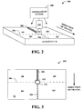
- Fig. 2 illustrates an exemplary, non-limiting embodiment of welding system 200 that detects a temperature at a location on the workpiece to reduce heat input inconsistencies during a welding operation.
- Fig. 3 illustrates a top view of Fig. 2 , yet Fig. 3 does not illustrate temperature sensor 108 so as to not obstruct the top view.
- Welding system 200 illustrates a portion of system 100 for the sake of brevity, yet it is to be appreciated controller 102 , power source 104 , and/or wire feeder 106 are utilized to create arc 112 between an electrode and workpiece W.
- Welding system 200 creates arc 112 to create weld 202 on workpiece W in which a travel direction indicates travel path 204, wherein travel path 204 is where a weld is to be created.
- Travel path 204 can be a reference to identify a first side and a second side of the workpiece in which the first side is area that includes at least location 208 and location 212 and the second side (opposite the first side) is area that includes location 210 and location 214.
- Temperature sensor 108 is configured to detect temperature at a location on workpiece W, wherein controller 102 (shown in at least Fig. 1 ) communicates an indication if such detected temperature exceeds a tolerance.
- controller 102 shown in at least Fig. 1
- temperature sensor 108 is affixed or coupled to torch head 110 .
- temperature sensor 108 can be affixed or coupled to at least one of a workpiece W, a support structure or device coupled to workpiece W or a portion of a welding system, a welding equipment, among others.
- Temperature sensor 108 can detect temperature at a location on workpiece W , and in particular on a surface of workpiece W in a location that is on at least one of the first side, the second side, or a combination thereof. For instance, the temperature can be detected at a distance away or from at least one of arc 112 , torch head 110 , weld 202, travel path 204, or a combination thereof.
- the temperature can be detected by temperature sensor 108 at one or more of a point in location 208, a point in location 212, a point in location 210, a point in location 214, a point along travel point 204, a point along weld 202, a point along reference numeral 206, a point below a surface weld 202 is created, an underside of workpiece W, an edge of workpiece W, among others.
- the temperature can be detected at a location that is aligned with at least one of arc 112 , torch head 110 , or electrode as indicated by reference numeral 206.
- the temperature can be detected at a location that is a distance from at least one of arc 112, torch head 110, or electrode and aligned with at least one of the arc 112, torch head 110, or electrode as indicated by reference numeral 206.
- This allows temperature sensor 108 to detect temperature at a location that is a distance from arc 112 and aligned with reference numeral 206 which is along a path that is parallel to travel path 204 and/or direction of travel for welding system 200.
- the temperature can be detected at location 208 (on the first side) or location 210 (on the second side) that is a distance from at least one of arc 112, torch head 110, or electrode and behind (e.g., lagging) the reference numeral 206.
- the temperature can be detected at location 212 (on the first side) or location 214 (on the second side) that is a distance from at least one of arc 112 , torch head 110 , or electrode and in front (e.g., leading) the reference numeral 206.
- the temperature can be detected at a location that is located on at least one of weld 202 or travel path 204.
- controller 102 can communicate an indication when the temperature exceeds a tolerance for such welding operation and/or type of material of workpiece W.
- system 200 can utilize two or more tolerances corresponding to two or more distances for a welding operation to glean heat input for a welding operation and to adjust the welding operation via controller 102 or a notification or indication to an operator in real time.
- Temperature sensor 108 can be configured to detect a first temperature a first distance from arc 112 in line with or along either weld 202 or travel path and a second temperature a second distance from arc 112 in line with or along reference numeral 206.
- Controller 102 can communicate an indication when 1) the detected first temperature exceeds a first tolerance for the first distance of the welding operation; and 2) the detected second temperature exceeds a second tolerance for the second distance of the welding operation.
- Such indication can be to an operator to adjust a travel speed for welding torch 110 or a wire feed speed.
- controller 102 can adjust the travel speed or the wire feed speed based on the one or more exceeded tolerances for the detected temperatures.
- temperature sensor 108 can be configured to detect temperature a depth below the surface of workpiece W. It is to be appreciated that system 200 can detect temperature on any surface of workpiece W or inside workpiece W. Moreover, a tolerance for each depth or location in or on workpiece W can be used for temperature to determine whether controller 102 communicates an indication.
- Temperature sensor 108 can detect one or more temperatures at one or more locations, wherein each of the one or more locations can have a respective temperature tolerance which defines at least one of a maximum temperature, a minimum temperature, a range of temperatures, among others.
- the respective temperature tolerance can be specific to a distance or a location on or within workpiece W.
- the temperature tolerance can be particular to a type of welding operation and/or a type of material of workpiece W.
- below is a table that illustrates tolerances in accordance with the subject innovation. It is to be appreciated that the below table is not exclusive and is solely an example since tolerances in accordance with the subject innovation can be determined for various parameters as discussed above.
- system 200 can utilize multiple temperature sensors (e.g., more than one temperature sensor 108 ).
- system 200 can include multiple metal deposition sources that deposit material onto a workpiece.
- metal depositions sources can work in series.
- a system can include two (2) metal deposition sources, wherein a first metal deposition source can deposit material first, and upon completion or during the same time, a second metal deposition source can deposit material after.
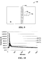
- Fig. 9 illustrates a top view of workpiece W having metal deposited (e.g., a weld) in which workpiece W has first temperature sensor (AI1) 902, second temperature sensor (AI2) 904, and third temperature sensor (AI3) 906 .
- Fig. 10 illustrates a graph of temperature and time for each temperature sensor. Below is Table 1 which illustrates more details for each: TABLE 1 Distance from Weld (mm) 13. 23. 33. Distance from Weld (in) 0.53 0.94 1.3 Thermo Couple AI1 (F) AI2 (F) AI3 (F) Max Temp (F) 1482 594 459 Max Temp (C) 805. 312. 237.
- the metal deposition process for the above can be a 25.4 mm (1 inch) wide bead (e.g., add .5 in total distance from weld.
- the location of the temperature sensors e.g., thermocouples
- the location of the temperature sensors can be approximately 152.4 mm to 228.6 mm (six [6] inches to nine [9] inches) from end plate dimensions 19.05 mm (3/4 inches) thick, 406.4 mm (16 inches) long, and 431.8 mm (17 inches) wide.
- the location can be 190.5 mm (7.5 inches) from the end plate.
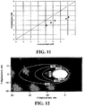
- Fig. 11 illustrates a predicted bead width graph versus measured bead width.
- Fig. 12 illustrates directional displacement in the Y direction versus directional displacement in the X direction, wherein the predicted bead width was from models and taking the liquidus temperature to be around 1400 C.
- a heat input versus bead width graph is illustrated.
- the heat input based on process parameters can be calculated.
- the bead width can be based on heat input from look-up tables. This can be converted into temperature contours such as shown in Fig. 12.
- Fig. 12 illustrates a heat contour that can be a prediction based on modeling and not by measurement.
- Fig. 12 illustrates how the thermal profile can look but often is inaccurately modeled because of the need to be measured in real time (which the subject application provides).
- Fig. 12 can be used to provide metrics such as heat affected zone width.
- the heat affected zone width can be used to generate a tolerance, wherein the tolerance can be based on fitting the actual temperature measured to a distance from the center of the bead of the weld and suggest a different travel speed or wire feed speed in order to achieve the appropriate heat affected zone width.
- heat affected zone width information is illustrated.
- the heat input can be calculated based on process parameters.
- the bead width can be determined based on heat input from a look-up table or pre-defined by a user or stored on a memory. This information can be converted into a temperature contour as shown in Fig. 12 and metrics such as heat affected zone width can be determined.
- the subject innovation can allow a determination of an accurate estimate of heat affected zone (HAZ) width from actual temperature measurements and fitting the actual temperature measurements to a distance from the center of the bead.
- the "tolerance” could be based on this fit to the predicted heat countour and suggest a different travel speed or wire feed speed in order to achieve the appropriate HAZ width.
- each type of welding operation and/or each type of material of workpiece W can include a temperature contour, wherein the temperature contour can include temperatures for distances from arc 112 and/or locations on or within workpiece W. For each location or distance, a tolerance can be defined.
- the definition of each temperature contour can be at least one of pre-defined, dynamically created based on user input or computer monitoring, downloaded or communicated from a cloud computing service, pre-defined and later updated based on welding operations performed, or a combination thereof.
- the temperature contour can further include information such as, but not limited to, temperatures or tolerances based on at least one of a distance from arc 112 and/or locations on or within workpiece W, maximum temperature for a location on or within workpiece W, minimum temperature for a location on or within workpiece W, range of temperatures allowed for a location on or within workpiece W, temperature or tolerance for a location based on a welding operation, temperature or tolerance for a location based on a type of material of workpiece W, temperature or tolerance for a type of electrode, temperature or tolerance for a welding operation, among others.
- Controller 102 can be configured to identify an average temperature of workpiece W based on receiving two or more temperature readings for one or more locations on or within workpiece W. Controller 102 can further communicate an indication when the average temperature of workpiece W exceeds a tolerance for the average temperature of such welding operation, and in particular, such workpiece.
- temperature sensor can detect a first temperature on a first location on the first side and detect a second temperature on a second location on the second side, wherein the first location on the first side is mirrored to the second location on the second side.
- controller can evaluate the average temperature of both the first temperature and the second temperature to a tolerance for the first location and/or the second location.
- temperature sensor can detect a first temperature on a first location on the first side and detect a second temperature on a second location on the second side, wherein the first location on the first side is not mirrored to the second location on the second side.
- controller can evaluate the first temperature and/or the second temperature to a tolerance respective to each first location and/or the second location.
- temperature sensor 108 can capture a baseline temperature of workpiece W to compare such baseline temperature to a temperature captured during the welding operation or after the welding operation. Such comparison can be used in evaluating the weld created and/or workpiece W and whether the weld created and/or workpiece W are suitable for a particular application or industry.
- controller 102 can be configured to evaluate a number of exceeded tolerances during a welding operation and generate a score which can be used to evaluate whether the weld created or workpiece W of the welding operation is suitable.
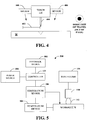
- Fig. 4 illustrates an exemplary, non-limiting embodiment of welding torch 110 that includes temperature sensor 108 to detect temperature at a location that is a distance from an arc created between an electrode and workpiece W. Torch 110 is illustrated in a travel direction coming out of the page of Fig. 4 . Temperature sensor 108 (referred to in Fig. 4 as "sensor 108 ”) can be removeably attached or incorporated into torch 110. In a particular embodiment, sensor 108 can be affixed to a first side of torch 110 corresponding to a side of workpiece W. Sensor 108 can detect temperature at a location that is distance 402 away from at least one of electrode 404 or welding torch 110 (also referred to as "torch 110" ).
- sensor 108 can detect temperature at a location that is distance 402 away from at least one of electrode 404 or welding torch 110 (also referred to as "torch 110" ).
- sensor 108 can be removeably attached or incorporated into torch 110.
- sensor 108 can be affixed to a first side of torch 110 corresponding to a side of workpiece W and additional sensor 406 can be affixed to a second side of torch 110 corresponding to a second side of workpiece W , wherein the first side of torch 110 is opposite the second side of torch 110 and the first side is opposite the second side.
- Sensor 108 and additional sensor 406 can detect temperatures at two or more locations that each have a respective distance away from at least one of electrode 404 or welding torch 110.
- Fig. 5 illustrates an exemplary, non-limiting embodiment of welding system 500 that communicates an indication to feedback device 502 based on a measured temperature of workpiece W at a distance adjacent to a travel path of welding torch 110.
- System 500 includes welding torch 110 having an electrode in which power source 104 creates arc 112 between electrode and workpiece W to complete an electrical circuit to perform the welding operation.
- System 500 can include power source 104 that is configured to create arc 112 between an electrode and workpiece W and further include wire feeder 106 is configured to deliver welding wire to a puddle formed by the electrode.
- Controller 102 can be configured to manage wire feed speed (WFS) of wire feeder 106, power source 104 that creates arc 112 for the welding operation.
- WFS wire feed speed
- Controller 102 is further configured to communicate an indication when a temperature detected by temperature sensor 108 exceeds or does not meet a tolerance.
- the indication can be communicated to an operator performing the welding operation in which the indication provides instruction to adjust wire feed speed and/or travel speed.
- controller 102 adjusts the wire feed speed in addition to an operator being notified to adjust travel speed in response to the temperature exceeding or not meeting a tolerance.
- controller can adjust the travel speed and/or the wire feed speed in response to the detected temperature not meeting or exceeding a tolerance.
- Controller 102 can communicate the indication to feedback device 502.
- Feedback device 502 can deliver the indication, wherein the indication can be, but is not limited to being auditory, visual, adaptive, haptic, among others.
- Feedback device 502 can be, but is not limited to, a speaker, a computer, a display, a cell phone, a tablet, a computing device, a siren, a light, an LED, a helmet, gloves, an electronic device, a wearable electronic device, or an apron.
- the indication can be a green light for within tolerance and a red light for outside tolerance, and such light can be flashed in a peripheral vision of the user via the helmet or welding lens of a helmet.
- the feedback device 502 can be a heads-up-display (HUD) that provides an image and/or a sound to indicate the operator performing the welding operation should adjust at least one of a welding parameter, a wire feed speed, and/or a travel speed.
- HUD heads-up-display
- a vibration can be used as an indication to an operator, wherein the vibration is provided by feedback device 502 being, such as, a welding torch, a glove, a wearable device, a welding helmet, a floor mat, a belt, an apron, among others.
- the indication can be a light or LED, wherein feedback device 502 receives the indication from controller 102 and the light or LED can signal when a tolerance is met or exceeded.
- colors for the light or LED can be designated to a particular indication (e.g., red for exceeding a tolerance, green for being within a tolerance).
- a HUD in a helmet can provide a graphic overlay with a heat map or infrared map of heat on the workpiece to illustrate heat input and/or tolerances being exceeded or not.
- System 500 further includes temperature device 504 that is configured to deliver additional heat or cooling to workpiece W based at least on detected temperature at a location on or within workpiece W.
- the temperature device 504 can be a heating element to increase heat input to a portion of workpiece W or at an area of workpiece W or a cooling element to decrease heat input to a portion of workpiece W or at an area of workpiece W.
- temperature device 504 can be used to adjust heat input to workpiece W instead of adjusting wire feed speed or travel speed.
- temperature device 504 can be used to adjust heat input to workpiece W in combination with adjusting wire feed speed and/or travel speed.
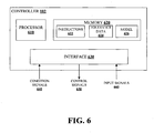
- controller 102 can be a microcontroller that includes a processor 610, a memory 620, and an interface 630.
- Processor 610 is configured to execute computer-executable instructions, such as instructions 622 stored by memory 620, for example.
- Instructions 622 comprise software executable by processor 610 to configure controller 102 to perform aspects described herein.
- Memory 620 can be non-transitory, computer-readable storage media including volatile storage media (e.g.
- Interface 630 can be a communications interface to enable controller 102 to communicate with other components such as welding power source 104, temperature sensor 108, etc.
- interface 630 can include general purpose input/output (I/O) pins, which can be coupled to various signal lines or circuit paths to transmit or receive signals.
- I/O input/output
- the interface 630 can be a connection to a data bus.
- interface 630 can be a wireless interface.
- Controller 102 via interface 630 , can receive condition signals 640 indicative of one or more conditions (e.g. environmental conditions, physical conditions, operational conditions, etc.) associated with the systems 100, 200, 300, 400, and/or 500.
- Tolerance data 624 stored by memory 620, can be generated based on condition signals 640.
- Processor 610 can employ model 626 with tolerance data 624 to determine, for example, communications for a feedback based on a temperature of a workpiece, travel speed for a welding operation for a temperature detected by a temperature sensor, a wire feed speed for a welding operation for a temperature detected by a temperature sensor, among others. Based on these determined quantities or values, controller 102 can generate control signals 650 transmitted by interface 630.
- Control signals 650 can be transmitted to power source 104 to limit a welding output generated thereby, or to a user interface to inform an operator of input limits (e.g. welding output preset limits) and/or to normalize inputs in accordance with the limits.
- limits can be, but are not limited to, a travel speed, a wire feed speed, a welding parameter, among others.
- interface 630 can receive input signals 660 (temperature readings, travel speed readings, wire feed speed, for example), which can be utilized to generate or supplement tolerance data 624, or establish settings (e.g. output presets) by which controller 102 implements via control signal 650.
- Model 626 can be a set of mathematical relationships correlating various conditions to temperature of the workpiece at a location that is a distance from the arc, temperature of a workpiece being a particular type of material, a distance from the arc for a workpiece, etc. as described above. Accordingly, processor 610 can utilize the set of mathematical relationships with tolerance data 624 to calculate deliverable power, travel speed, wire feed speed, or a welding parameter. In another example, model 626 can be based on empirical data. For instance, for the respective conditions and, specifically respective levels or values for the conditions, results can be experimentally measured and collected. The results can be, for example, actual measurements of temperatures under varying conditions for various types of materials that can be a workpiece.
- model 626 utilized to determine or interpolate desired quantities based on tolerance data 624 gathered by controller 102.
- the empirical data is utilized to generate to train model 626 via artificial intelligence or machine learning techniques.
- model 626 can be a neural network or other classification scheme that is trained on the empirical data to develop relationships between temperature of the workpiece and travel speed and/or wire feed speed. The developed relationships can be utilized to determine welding parameters from new condition inputs in situ.
- model 626 can include or involve, for instance, a neural network, a decision tree, an association rule, a support vector machine, a Bayesian network, genetic algorithms, or the like.
- the welding parameter can be, but is not limited to, a type of welding operation, a type of shielding gas, a material composition of workpiece W, a welding pattern, a type of electrode, a composition of electrode, a wire feed speed, a waveform used for the welding operation, a polarity of a welding wire, a type of flux, a number of electrodes used in the welding operation, an arc voltage, a travel speed of a tractor welder that performs the welding operation, a travel speed of a torch that performs the welding operation, an arc current level, a height of torch, a distance between workpiece W and torch or an end of the electrode, an oscillation width of electrode, a temperature of welding wire, a temperature of electrode, a type of material of workpiece W, a frequency of oscillation of electrode, a polarity of the arc current, a polarity of the current for welding wire, a parameter that affects an arc current of the welding operation, a gauge of wire,
- the indication informs an operator to adjust a travel speed of the welding torch along the weld joint to bring the temperature of the workpiece into compliance.
- the system can include a wire feeder configured to deliver a welding wire to the arc, wherein the controller is configured to adjust a wire feed speed of the wire feeder when the temperature of the workpiece exceeds the tolerance.
- the controller is configured to calibrate the tolerance based at least one of the material of the workpiece, a distance from the arc, or a welding process.
- the system can include the temperature sensor is further configured to detect an additional temperature of the workpiece at an additional path and the controller is further configured to communicate the indication to a feedback device when an average temperature of the temperature and the additional temperature exceed the tolerance.
- the path is a location that is aligned with the welding torch and parallel to a travel path of the welding torch. In an embodiment, the path is a location that is in front of the welding torch, a distance from the electrode, and parallel to a travel path of the welding torch. In an embodiment, the path is a location that is behind the welding torch, a distance from the electrode, and parallel to a travel path of the welding torch.
- the system can include the temperature sensor is affixed to the welding torch and detects the temperature of the workpiece along the path adjacent to the weld joint during the welding operation with the path being on a first side of the workpiece and a distance from the arc.
- the system can include an additional temperature sensor affixed to the welding torch configured to detect an additional temperature of the workpiece along an additional path adjacent to the weld joint during the welding operation with the additional path being on a second side of the workpiece and the distance from the arc, the first side is opposite the second side with a travel path of the welding torch therebetween.
- the controller further configured to communicate the indication to the feedback device when an average temperature of the workpiece exceeds the tolerance associated with the material of the workpiece, wherein the average temperature is of the temperature on the path on the first side and the additional temperature on the additional path on the second side.
- the indication is a visual indicator and the feedback device is a helmet. In an embodiment, the indication is a haptic feedback and the feedback device is at least one of a glove or a welding torch.
- the controller increases the wire feed speed of the wire feeder when the temperature of the workpiece is below a minimum temperature used to calculate the tolerance. In an embodiment, the controller decreases the wire feed speed of the wire feeder when the temperature of the workpiece is above a maximum temperature used to calculate the tolerance.
- the system can further include the temperature sensor detects the temperature of the workpiece along the path adjacent to the weld joint during the welding operation with the path being a first distance from the arc; the temperature sensor detects an additional temperature of the workpiece along an additional path adjacent to the weld joint during the welding operation with the additional path being on a second distance from the arc; and the controller further configured to communicate the indication to the feedback device when the temperature or the additional temperature of the workpiece exceeds the tolerance associated with the material of the workpiece for the first distance or the second distance.
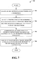
- Fig. 7 is a flow diagram 700 that detects temperature of a workpiece to reduce inconsistency of heat input for a welding operation.
- an arc between an electrode and a workpiece can be created.
- a temperature of the workpiece at a location that is a distance from the arc can be detected, wherein the location is parallel to a travel path of the electrode.
- the temperature is continuously being detected in real time along a path that can be adjacent to the travel path of the electrode.
- the temperature can be detected along a path (or paths for more than one temperature sensor) that is parallel to the travel path of the electrode on either side of the electrode.
- an indication can be communicated to a feedback device when the detected temperature of the workpiece exceeds a tolerance.
- at least one of a travel speed or a wire feed speed for wire delivery to the arc can be adjusted based on the detected temperature.
- at least one of the wire feed speed or the travel speed can be maintained, increased, or decreased based on the detected temperature being within the tolerance, above a maximum temperature used to calculate the tolerance, or below a minimum temperature used to calculate the tolerance.
- Fig. 8 illustrates a flow diagram 800 that communicates feedback based on a monitored temperature of a workpiece at a location that is a distance from the arc created on such workpiece.
- an actual temperature of a location on a workpiece can be monitored, wherein the location is a distance from an arc created between an electrode and the workpiece.
- a temperature for a type of material of the workpiece can be received.
- a feedback can be communicated based on detection of an actual temperature at a location on the workpiece that is outside a tolerance for the temperature.
- a tolerance can be based on a distance from an arc for a particular type of material of a workpiece and such tolerance can be a range of temperatures (e.g., a minimum temperature to a high temperature).
- the tolerance can be a percentage of a target temperature for a particular type of material of a workpiece at a specific distance (e.g., a ⁇ five percent of a target temperature).
- the indication informs an operator to adjust a travel speed of a welding torch to bring the temperature of the workpiece into compliance of the tolerance.
- the method can include detecting an additional temperature of the workpiece at an additional location that is an additional distance from the arc, aligned with the arc, and parallel to the travel path of the electrode and communicating the indication to the feedback device when the detected temperature or additional temperature of the workpiece exceeds the tolerance for the distance or the additional distance.
- the method includes calibrating the tolerance based at least one of the type of material of the workpiece, a distance from the arc, or a welding process.
- a power supply as used herein can be a power supply for a device that performs welding, arc welding, laser welding, brazing, soldering, plasma cutting, waterjet cutting, laser cutting, among others.
- welding power supply e.g., welding power supply, among others
- one of sound engineering and judgment can choose power supplies other than a welding power supply departing from the intended scope of coverage of the embodiments of the subject invention.
Landscapes
- Engineering & Computer Science (AREA)
- Physics & Mathematics (AREA)
- Plasma & Fusion (AREA)
- Mechanical Engineering (AREA)
- Chemical & Material Sciences (AREA)
- Materials Engineering (AREA)
- Theoretical Computer Science (AREA)
- Arc Welding Control (AREA)
- Arc Welding In General (AREA)
Applications Claiming Priority (1)
| Application Number | Priority Date | Filing Date | Title |
|---|---|---|---|
| US15/210,089 US10682721B2 (en) | 2016-07-14 | 2016-07-14 | Method and system for welding with temperature detector |
Publications (3)
| Publication Number | Publication Date |
|---|---|
| EP3272450A2 EP3272450A2 (en) | 2018-01-24 |
| EP3272450A3 EP3272450A3 (en) | 2018-02-28 |
| EP3272450B1 true EP3272450B1 (en) | 2020-09-09 |
Family
ID=59350598
Family Applications (1)
| Application Number | Title | Priority Date | Filing Date |
|---|---|---|---|
| EP17001193.6A Active EP3272450B1 (en) | 2016-07-14 | 2017-07-13 | Method of and system for welding with a torch, a temperature detector and a controller |
Country Status (4)
| Country | Link |
|---|---|
| US (1) | US10682721B2 (enExample) |
| EP (1) | EP3272450B1 (enExample) |
| JP (1) | JP2018008313A (enExample) |
| CN (1) | CN107617807B (enExample) |
Families Citing this family (8)
| Publication number | Priority date | Publication date | Assignee | Title |
|---|---|---|---|---|
| US10839195B2 (en) * | 2017-08-08 | 2020-11-17 | Uchicago Argonne, Llc | Machine learning technique to identify grains in polycrystalline materials samples |
| JP7263651B2 (ja) * | 2018-11-08 | 2023-04-25 | トーヨーカネツ株式会社 | 遠隔制御溶接システム |
| US20200238420A1 (en) * | 2019-01-25 | 2020-07-30 | Northrop Grumman Systems Corporation | Control system using light signal feedback to guide welding operations |
| US11806814B2 (en) | 2019-02-19 | 2023-11-07 | Illinois Tool Works Inc. | Welding location and order monitoring in welding systems |
| JP6818069B2 (ja) * | 2019-03-08 | 2021-01-20 | 櫻護謨株式会社 | 溶接面および溶接方法 |
| WO2021058837A1 (es) * | 2019-09-24 | 2021-04-01 | Lortek S. Coop. | Sistema inteligente de protección local con control de temperatura para procesos de fabricación aditiva mediante arco e hilo |
| JP7498141B2 (ja) * | 2021-04-20 | 2024-06-11 | 株式会社神戸製鋼所 | 溶接システム、溶接方法、溶接ロボット及びプログラム |
| CN117182289A (zh) * | 2022-05-31 | 2023-12-08 | 广东舜元激光科技有限公司 | 一种铝塑膜焊接装置及铝塑膜焊接方法 |
Citations (1)
| Publication number | Priority date | Publication date | Assignee | Title |
|---|---|---|---|---|
| US20140124491A1 (en) * | 2012-11-07 | 2014-05-08 | Lincoln Global, Inc. | Method and system to control heat input in a welding operation |
Family Cites Families (49)
| Publication number | Priority date | Publication date | Assignee | Title |
|---|---|---|---|---|
| US3867769A (en) * | 1973-08-06 | 1975-02-25 | Harvey B Schow | Arc welding simulator trainer |
| JPS5381452A (en) * | 1976-12-28 | 1978-07-18 | Yanagawa Seiki Co Ltd | Device of detecting welded condition |
| DE59402598D1 (de) * | 1993-11-30 | 1997-06-05 | Elpatronic Ag | Gleichzeitige Temperaturmessungen an Laserschweissnähten mit mindestens zwei Pyrometern und Zuordnung zu Prozessparametern und Nahtqualität |
| US5811055A (en) * | 1996-02-06 | 1998-09-22 | Geiger; Michael B. | Torch mounted gas scavaging system for manual and robotic welding and cutting torches |
| GB2349082A (en) | 1999-04-23 | 2000-10-25 | Gb Solo Limited | Helmet |
| SE515707C2 (sv) | 2000-02-11 | 2001-10-01 | Nekp Sweden Ab | Skyddsanordning vid metallsvetsning eller - skärning innefattande presentation av processdata |
| SE515709C2 (sv) | 2000-02-11 | 2001-10-01 | Nekp Sweden Ab | Skyddsanordning vid metallsvetsning eller - skärning |
| FI20001563A0 (fi) | 2000-06-30 | 2000-06-30 | Tom L Kuutti | Tilanneilmaisin pelastuspalvelua varten |
| US20050252898A1 (en) | 2002-07-04 | 2005-11-17 | Kurt Blechinger | Method for operating a welding device, and one such welding device |
| US7298535B2 (en) | 2003-01-03 | 2007-11-20 | Tommi Lennart Kuutti | Digital situation indicator |
| US6995338B2 (en) | 2003-03-31 | 2006-02-07 | Illinois Tool Works Inc. | Method and apparatus for short circuit welding |
| US20060010551A1 (en) | 2004-07-14 | 2006-01-19 | Bishop Timothy D | Welding face covering |
| JP2007237213A (ja) | 2006-03-07 | 2007-09-20 | Toshiba Corp | 溶接トーチおよび溶接トーチを用いた溶接システム |
| US20100088793A1 (en) | 2006-06-06 | 2010-04-15 | Livio Ghisleni | Face and antiglare protection device for persons working in sites involving hazardous, damaging or disturbing radiation, especially welders |
| US20080082179A1 (en) | 2006-09-28 | 2008-04-03 | Yea-Chyi Yang | Eye guard with voice indication |
| DE102007036505A1 (de) | 2007-08-01 | 2009-02-12 | Ewm Hightec Welding Gmbh | Verfahren , Vorrichtung und System zur Ermittlung einer Schweißgeschwindigkeit bei einem manuell ausgeführten Lichtbogenschweißvorgang |
| DE202007011584U1 (de) | 2007-08-17 | 2009-01-02 | Interforge Klee Gmbh | Schweißgerät |
| US8354608B2 (en) | 2009-05-14 | 2013-01-15 | B6 Sigma, Inc. | Methods for control of a fusion welding process by maintaining a controlled weld pool volume |
| US10748447B2 (en) | 2013-05-24 | 2020-08-18 | Lincoln Global, Inc. | Systems and methods providing a computerized eyewear device to aid in welding |
| EP2292363B1 (de) | 2009-09-08 | 2017-01-04 | Ewm Ag | Verfahren und Vorrichtung zum Ermitteln einer Schweiß- oder Lötgeschwindigkeit |
| JP5573464B2 (ja) | 2010-08-03 | 2014-08-20 | セイコーエプソン株式会社 | 投射型表示装置及びその制御方法 |
| JP5490044B2 (ja) | 2011-03-14 | 2014-05-14 | 株式会社東芝 | 携帯可能電子装置、及び携帯可能電子装置の制御方法 |
| US9073138B2 (en) | 2011-05-16 | 2015-07-07 | Lincoln Global, Inc. | Dual-spectrum digital imaging welding helmet |
| JP5916308B2 (ja) | 2011-07-20 | 2016-05-11 | ウィンテックポリマー株式会社 | 樹脂ペレットの製造方法及び自動車内装部品 |
| KR101219182B1 (ko) | 2011-08-22 | 2013-01-21 | (주)티엘씨테크놀로지 | 스마트 안전관리 운용 시스템 |
| CA2867895C (en) | 2012-03-19 | 2018-03-06 | Flir Systems, Inc. | Wearable apparatus with integrated infrared imaging module |
| US8657179B1 (en) | 2012-03-26 | 2014-02-25 | The United States Of America As Represented By The Administrator Of The National Aeronautics And Space Administration | Weld nugget temperature control in thermal stir welding |
| US9266182B2 (en) | 2012-04-06 | 2016-02-23 | Illinois Tools Works Inc. | Welding torch with a temperature measurement device |
| US9415459B2 (en) | 2012-04-06 | 2016-08-16 | Illinois Tool Works Inc. | Welding systems having non-contact temperature measurement systems |
| KR101314553B1 (ko) | 2012-04-13 | 2013-10-07 | 민성정보기술(주) | 영상 전송 기능을 갖는 용접면을 이용한 용접 상태 검출 장치 |
| US9566192B2 (en) | 2012-05-04 | 2017-02-14 | Illinois Tool Works Inc. | Welding helmet for detecting arc data |
| CN102744880A (zh) | 2012-06-28 | 2012-10-24 | 王�琦 | 电熔焊机以及电熔管件的焊接方法 |
| JP2014108456A (ja) | 2012-12-04 | 2014-06-12 | Mitsubishi Heavy Ind Ltd | 溶接品質自動管理装置および溶接品質自動管理方法 |
| CN103115737A (zh) * | 2013-01-20 | 2013-05-22 | 肖栋 | 一种管道焊接口检测器 |
| US20140210987A1 (en) | 2013-01-31 | 2014-07-31 | Chad Adkins | Temperature Display Helmet |
| US10213862B2 (en) * | 2013-05-10 | 2019-02-26 | Illinois Tool Works Inc. | Welding system for determining a quality of a welding operation |
| US11090753B2 (en) | 2013-06-21 | 2021-08-17 | Illinois Tool Works Inc. | System and method for determining weld travel speed |
| CN103364108A (zh) * | 2013-07-02 | 2013-10-23 | 英利集团有限公司 | 焊接温度检测装置、焊接机及焊接温度的校准方法 |
| DE202013103383U1 (de) | 2013-07-26 | 2014-10-27 | Wegener International Gmbh | Handschweißgerät zum Verschweißen von Werkstücken aus thermoplastischem Kunststoff |
| CN104869354A (zh) | 2014-02-26 | 2015-08-26 | 杭州美盛红外光电技术有限公司 | 头盔式热像装置 |
| CN103862136B (zh) * | 2014-03-14 | 2015-08-12 | 吉林大学 | 熔焊过程的监测装置及监测方法 |
| US9808882B2 (en) | 2014-06-25 | 2017-11-07 | Illinois Tool Works Inc. | System and method for controlling wire feed speed |
| CN104353925B (zh) | 2014-10-31 | 2016-10-19 | 浙江久德不锈钢型材有限公司 | 一种焊机送丝机装置 |
| CN104475897B (zh) | 2014-11-27 | 2017-03-15 | 沪东中华造船(集团)有限公司 | 一种铝钢cmt熔钎焊接过程控制方法 |
| US10773329B2 (en) | 2015-01-20 | 2020-09-15 | Illinois Tool Works Inc. | Multiple input welding vision system |
| US10448692B2 (en) | 2015-03-06 | 2019-10-22 | Illinois Tool Works Inc. | Sensor assisted head mounted displays for welding |
| CN107980153B (zh) | 2015-03-09 | 2021-10-22 | 伊利诺斯工具制品有限公司 | 提供与焊接操作相关联的视觉信息的方法和装置 |
| US9977242B2 (en) * | 2015-03-26 | 2018-05-22 | Illinois Tool Works Inc. | Control of mediated reality welding system based on lighting conditions |
| CN104889535A (zh) * | 2015-05-15 | 2015-09-09 | 无锡阳工机械制造有限公司 | 基于氩弧焊的智能焊接工艺 |
-
2016
- 2016-07-14 US US15/210,089 patent/US10682721B2/en active Active
-
2017
- 2017-07-06 CN CN201710546122.4A patent/CN107617807B/zh active Active
- 2017-07-12 JP JP2017136029A patent/JP2018008313A/ja active Pending
- 2017-07-13 EP EP17001193.6A patent/EP3272450B1/en active Active
Patent Citations (1)
| Publication number | Priority date | Publication date | Assignee | Title |
|---|---|---|---|---|
| US20140124491A1 (en) * | 2012-11-07 | 2014-05-08 | Lincoln Global, Inc. | Method and system to control heat input in a welding operation |
Also Published As
| Publication number | Publication date |
|---|---|
| US20180015559A1 (en) | 2018-01-18 |
| CN107617807B (zh) | 2021-07-20 |
| EP3272450A3 (en) | 2018-02-28 |
| EP3272450A2 (en) | 2018-01-24 |
| JP2018008313A (ja) | 2018-01-18 |
| US10682721B2 (en) | 2020-06-16 |
| CN107617807A (zh) | 2018-01-23 |
Similar Documents
| Publication | Publication Date | Title |
|---|---|---|
| EP3395487B1 (en) | Welding helmet with temperature detector, and welding system with such and welding helmet | |
| EP3272450B1 (en) | Method of and system for welding with a torch, a temperature detector and a controller | |
| US20180015560A1 (en) | Method and system for welding with temperature detector | |
| US12090583B2 (en) | Systems and methods for adaptive control of wire preheating | |
| EP3010677B1 (en) | System and method for determining weld travel speed | |
| CN106457468B (zh) | 使用两个机器人的混合激光焊接系统和方法 | |
| US20070181548A1 (en) | Welding process | |
| CN110814470B (zh) | 一种焊接设备及其焊接参数调整方法和装置 | |
| CN110446577B (zh) | 焊接状态判定系统以及焊接状态判定方法 | |
| US9700953B2 (en) | Adaptive welding apparatus, control system, and method of controlling an adaptive welding apparatus | |
| US20230234153A1 (en) | Method for defining welding parameters for a welding process on a workpiece and welding device for carrying out a welding process on a workpiece with defined welding parameters | |
| JP2020108894A (ja) | 溶接作業条件導出装置、溶接電源装置、および溶接技術習得装置 | |
| JP6672551B2 (ja) | アーク溶接の表示装置及び表示方法 | |
| KR102378250B1 (ko) | 루트패스 백비드 용접 시 갭 센싱을 통한 송급속도 조절 장치 및 방법 | |
| CN116829289A (zh) | 造型履历监视装置、造型物的制造系统以及造型履历监视方法 | |
| US20250353099A1 (en) | Welding method and welding device | |
| US20210302934A1 (en) | Methods and systems using data logging power supply for improved welding and heating | |
| CN121535339A (zh) | 用于激光焊接的激光能量与光斑摆动协同控制方法及系统 |
Legal Events
| Date | Code | Title | Description |
|---|---|---|---|
| PUAI | Public reference made under article 153(3) epc to a published international application that has entered the european phase |
Free format text: ORIGINAL CODE: 0009012 |
|
| STAA | Information on the status of an ep patent application or granted ep patent |
Free format text: STATUS: THE APPLICATION HAS BEEN PUBLISHED |
|
| AK | Designated contracting states |
Kind code of ref document: A2 Designated state(s): AL AT BE BG CH CY CZ DE DK EE ES FI FR GB GR HR HU IE IS IT LI LT LU LV MC MK MT NL NO PL PT RO RS SE SI SK SM TR |
|
| AX | Request for extension of the european patent |
Extension state: BA ME |
|
| PUAL | Search report despatched |
Free format text: ORIGINAL CODE: 0009013 |
|
| AK | Designated contracting states |
Kind code of ref document: A3 Designated state(s): AL AT BE BG CH CY CZ DE DK EE ES FI FR GB GR HR HU IE IS IT LI LT LU LV MC MK MT NL NO PL PT RO RS SE SI SK SM TR |
|
| AX | Request for extension of the european patent |
Extension state: BA ME |
|
| RIC1 | Information provided on ipc code assigned before grant |
Ipc: B23K 9/095 20060101AFI20180125BHEP Ipc: B23K 9/23 20060101ALI20180125BHEP Ipc: B23K 9/12 20060101ALI20180125BHEP Ipc: B23K 9/127 20060101ALI20180125BHEP Ipc: B23K 9/173 20060101ALI20180125BHEP |
|
| STAA | Information on the status of an ep patent application or granted ep patent |
Free format text: STATUS: REQUEST FOR EXAMINATION WAS MADE |
|
| 17P | Request for examination filed |
Effective date: 20180828 |
|
| RBV | Designated contracting states (corrected) |
Designated state(s): AL AT BE BG CH CY CZ DE DK EE ES FI FR GB GR HR HU IE IS IT LI LT LU LV MC MK MT NL NO PL PT RO RS SE SI SK SM TR |
|
| STAA | Information on the status of an ep patent application or granted ep patent |
Free format text: STATUS: EXAMINATION IS IN PROGRESS |
|
| 17Q | First examination report despatched |
Effective date: 20190128 |
|
| GRAP | Despatch of communication of intention to grant a patent |
Free format text: ORIGINAL CODE: EPIDOSNIGR1 |
|
| STAA | Information on the status of an ep patent application or granted ep patent |
Free format text: STATUS: GRANT OF PATENT IS INTENDED |
|
| INTG | Intention to grant announced |
Effective date: 20200211 |
|
| GRAS | Grant fee paid |
Free format text: ORIGINAL CODE: EPIDOSNIGR3 |
|
| GRAA | (expected) grant |
Free format text: ORIGINAL CODE: 0009210 |
|
| STAA | Information on the status of an ep patent application or granted ep patent |
Free format text: STATUS: THE PATENT HAS BEEN GRANTED |
|
| AK | Designated contracting states |
Kind code of ref document: B1 Designated state(s): AL AT BE BG CH CY CZ DE DK EE ES FI FR GB GR HR HU IE IS IT LI LT LU LV MC MK MT NL NO PL PT RO RS SE SI SK SM TR |
|
| REG | Reference to a national code |
Ref country code: GB Ref legal event code: FG4D |
|
| REG | Reference to a national code |
Ref country code: AT Ref legal event code: REF Ref document number: 1310957 Country of ref document: AT Kind code of ref document: T Effective date: 20200915 Ref country code: CH Ref legal event code: EP |
|
| REG | Reference to a national code |
Ref country code: IE Ref legal event code: FG4D |
|
| REG | Reference to a national code |
Ref country code: DE Ref legal event code: R096 Ref document number: 602017023077 Country of ref document: DE |
|
| REG | Reference to a national code |
Ref country code: FI Ref legal event code: FGE |
|
| REG | Reference to a national code |
Ref country code: SE Ref legal event code: TRGR |
|
| REG | Reference to a national code |
Ref country code: LT Ref legal event code: MG4D |
|
| PG25 | Lapsed in a contracting state [announced via postgrant information from national office to epo] |
Ref country code: BG Free format text: LAPSE BECAUSE OF FAILURE TO SUBMIT A TRANSLATION OF THE DESCRIPTION OR TO PAY THE FEE WITHIN THE PRESCRIBED TIME-LIMIT Effective date: 20201209 Ref country code: NO Free format text: LAPSE BECAUSE OF FAILURE TO SUBMIT A TRANSLATION OF THE DESCRIPTION OR TO PAY THE FEE WITHIN THE PRESCRIBED TIME-LIMIT Effective date: 20201209 Ref country code: HR Free format text: LAPSE BECAUSE OF FAILURE TO SUBMIT A TRANSLATION OF THE DESCRIPTION OR TO PAY THE FEE WITHIN THE PRESCRIBED TIME-LIMIT Effective date: 20200909 Ref country code: GR Free format text: LAPSE BECAUSE OF FAILURE TO SUBMIT A TRANSLATION OF THE DESCRIPTION OR TO PAY THE FEE WITHIN THE PRESCRIBED TIME-LIMIT Effective date: 20201210 Ref country code: LT Free format text: LAPSE BECAUSE OF FAILURE TO SUBMIT A TRANSLATION OF THE DESCRIPTION OR TO PAY THE FEE WITHIN THE PRESCRIBED TIME-LIMIT Effective date: 20200909 |
|
| REG | Reference to a national code |
Ref country code: NL Ref legal event code: MP Effective date: 20200909 |
|
| PG25 | Lapsed in a contracting state [announced via postgrant information from national office to epo] |
Ref country code: LV Free format text: LAPSE BECAUSE OF FAILURE TO SUBMIT A TRANSLATION OF THE DESCRIPTION OR TO PAY THE FEE WITHIN THE PRESCRIBED TIME-LIMIT Effective date: 20200909 Ref country code: PL Free format text: LAPSE BECAUSE OF FAILURE TO SUBMIT A TRANSLATION OF THE DESCRIPTION OR TO PAY THE FEE WITHIN THE PRESCRIBED TIME-LIMIT Effective date: 20200909 Ref country code: RS Free format text: LAPSE BECAUSE OF FAILURE TO SUBMIT A TRANSLATION OF THE DESCRIPTION OR TO PAY THE FEE WITHIN THE PRESCRIBED TIME-LIMIT Effective date: 20200909 |
|
| PG25 | Lapsed in a contracting state [announced via postgrant information from national office to epo] |
Ref country code: CZ Free format text: LAPSE BECAUSE OF FAILURE TO SUBMIT A TRANSLATION OF THE DESCRIPTION OR TO PAY THE FEE WITHIN THE PRESCRIBED TIME-LIMIT Effective date: 20200909 Ref country code: PT Free format text: LAPSE BECAUSE OF FAILURE TO SUBMIT A TRANSLATION OF THE DESCRIPTION OR TO PAY THE FEE WITHIN THE PRESCRIBED TIME-LIMIT Effective date: 20210111 Ref country code: RO Free format text: LAPSE BECAUSE OF FAILURE TO SUBMIT A TRANSLATION OF THE DESCRIPTION OR TO PAY THE FEE WITHIN THE PRESCRIBED TIME-LIMIT Effective date: 20200909 Ref country code: EE Free format text: LAPSE BECAUSE OF FAILURE TO SUBMIT A TRANSLATION OF THE DESCRIPTION OR TO PAY THE FEE WITHIN THE PRESCRIBED TIME-LIMIT Effective date: 20200909 Ref country code: SM Free format text: LAPSE BECAUSE OF FAILURE TO SUBMIT A TRANSLATION OF THE DESCRIPTION OR TO PAY THE FEE WITHIN THE PRESCRIBED TIME-LIMIT Effective date: 20200909 |
|
| PG25 | Lapsed in a contracting state [announced via postgrant information from national office to epo] |
Ref country code: ES Free format text: LAPSE BECAUSE OF FAILURE TO SUBMIT A TRANSLATION OF THE DESCRIPTION OR TO PAY THE FEE WITHIN THE PRESCRIBED TIME-LIMIT Effective date: 20200909 Ref country code: AL Free format text: LAPSE BECAUSE OF FAILURE TO SUBMIT A TRANSLATION OF THE DESCRIPTION OR TO PAY THE FEE WITHIN THE PRESCRIBED TIME-LIMIT Effective date: 20200909 Ref country code: IS Free format text: LAPSE BECAUSE OF FAILURE TO SUBMIT A TRANSLATION OF THE DESCRIPTION OR TO PAY THE FEE WITHIN THE PRESCRIBED TIME-LIMIT Effective date: 20210109 |
|
| REG | Reference to a national code |
Ref country code: DE Ref legal event code: R097 Ref document number: 602017023077 Country of ref document: DE |
|
| PG25 | Lapsed in a contracting state [announced via postgrant information from national office to epo] |
Ref country code: SK Free format text: LAPSE BECAUSE OF FAILURE TO SUBMIT A TRANSLATION OF THE DESCRIPTION OR TO PAY THE FEE WITHIN THE PRESCRIBED TIME-LIMIT Effective date: 20200909 |
|
| REG | Reference to a national code |
Ref country code: AT Ref legal event code: UEP Ref document number: 1310957 Country of ref document: AT Kind code of ref document: T Effective date: 20200909 |
|
| PLBE | No opposition filed within time limit |
Free format text: ORIGINAL CODE: 0009261 |
|
| STAA | Information on the status of an ep patent application or granted ep patent |
Free format text: STATUS: NO OPPOSITION FILED WITHIN TIME LIMIT |
|
| 26N | No opposition filed |
Effective date: 20210610 |
|
| PG25 | Lapsed in a contracting state [announced via postgrant information from national office to epo] |
Ref country code: SI Free format text: LAPSE BECAUSE OF FAILURE TO SUBMIT A TRANSLATION OF THE DESCRIPTION OR TO PAY THE FEE WITHIN THE PRESCRIBED TIME-LIMIT Effective date: 20200909 Ref country code: DK Free format text: LAPSE BECAUSE OF FAILURE TO SUBMIT A TRANSLATION OF THE DESCRIPTION OR TO PAY THE FEE WITHIN THE PRESCRIBED TIME-LIMIT Effective date: 20200909 |
|
| PG25 | Lapsed in a contracting state [announced via postgrant information from national office to epo] |
Ref country code: IT Free format text: LAPSE BECAUSE OF FAILURE TO SUBMIT A TRANSLATION OF THE DESCRIPTION OR TO PAY THE FEE WITHIN THE PRESCRIBED TIME-LIMIT Effective date: 20200909 |
|
| REG | Reference to a national code |
Ref country code: CH Ref legal event code: PL |
|
| GBPC | Gb: european patent ceased through non-payment of renewal fee |
Effective date: 20210713 |
|
| PG25 | Lapsed in a contracting state [announced via postgrant information from national office to epo] |
Ref country code: MC Free format text: LAPSE BECAUSE OF FAILURE TO SUBMIT A TRANSLATION OF THE DESCRIPTION OR TO PAY THE FEE WITHIN THE PRESCRIBED TIME-LIMIT Effective date: 20200909 |
|
| REG | Reference to a national code |
Ref country code: BE Ref legal event code: MM Effective date: 20210731 |
|
| PG25 | Lapsed in a contracting state [announced via postgrant information from national office to epo] |
Ref country code: LI Free format text: LAPSE BECAUSE OF NON-PAYMENT OF DUE FEES Effective date: 20210731 Ref country code: GB Free format text: LAPSE BECAUSE OF NON-PAYMENT OF DUE FEES Effective date: 20210713 Ref country code: CH Free format text: LAPSE BECAUSE OF NON-PAYMENT OF DUE FEES Effective date: 20210731 |
|
| PG25 | Lapsed in a contracting state [announced via postgrant information from national office to epo] |
Ref country code: LU Free format text: LAPSE BECAUSE OF NON-PAYMENT OF DUE FEES Effective date: 20210713 Ref country code: FR Free format text: LAPSE BECAUSE OF NON-PAYMENT OF DUE FEES Effective date: 20210731 |
|
| PG25 | Lapsed in a contracting state [announced via postgrant information from national office to epo] |
Ref country code: IE Free format text: LAPSE BECAUSE OF NON-PAYMENT OF DUE FEES Effective date: 20210713 Ref country code: BE Free format text: LAPSE BECAUSE OF NON-PAYMENT OF DUE FEES Effective date: 20210731 |
|
| PG25 | Lapsed in a contracting state [announced via postgrant information from national office to epo] |
Ref country code: HU Free format text: LAPSE BECAUSE OF FAILURE TO SUBMIT A TRANSLATION OF THE DESCRIPTION OR TO PAY THE FEE WITHIN THE PRESCRIBED TIME-LIMIT; INVALID AB INITIO Effective date: 20170713 |
|
| PG25 | Lapsed in a contracting state [announced via postgrant information from national office to epo] |
Ref country code: NL Free format text: LAPSE BECAUSE OF NON-PAYMENT OF DUE FEES Effective date: 20200923 Ref country code: CY Free format text: LAPSE BECAUSE OF FAILURE TO SUBMIT A TRANSLATION OF THE DESCRIPTION OR TO PAY THE FEE WITHIN THE PRESCRIBED TIME-LIMIT Effective date: 20200909 |
|
| PG25 | Lapsed in a contracting state [announced via postgrant information from national office to epo] |
Ref country code: MK Free format text: LAPSE BECAUSE OF FAILURE TO SUBMIT A TRANSLATION OF THE DESCRIPTION OR TO PAY THE FEE WITHIN THE PRESCRIBED TIME-LIMIT Effective date: 20200909 |
|
| PG25 | Lapsed in a contracting state [announced via postgrant information from national office to epo] |
Ref country code: MT Free format text: LAPSE BECAUSE OF FAILURE TO SUBMIT A TRANSLATION OF THE DESCRIPTION OR TO PAY THE FEE WITHIN THE PRESCRIBED TIME-LIMIT Effective date: 20200909 |
|
| PGFP | Annual fee paid to national office [announced via postgrant information from national office to epo] |
Ref country code: FI Payment date: 20250722 Year of fee payment: 9 |
|
| PGFP | Annual fee paid to national office [announced via postgrant information from national office to epo] |
Ref country code: DE Payment date: 20250722 Year of fee payment: 9 |
|
| PGFP | Annual fee paid to national office [announced via postgrant information from national office to epo] |
Ref country code: AT Payment date: 20250721 Year of fee payment: 9 |
|
| PGFP | Annual fee paid to national office [announced via postgrant information from national office to epo] |
Ref country code: SE Payment date: 20250723 Year of fee payment: 9 |
|
| PG25 | Lapsed in a contracting state [announced via postgrant information from national office to epo] |
Ref country code: TR Free format text: LAPSE BECAUSE OF FAILURE TO SUBMIT A TRANSLATION OF THE DESCRIPTION OR TO PAY THE FEE WITHIN THE PRESCRIBED TIME-LIMIT Effective date: 20200909 |