EP3272049B1 - Carrier aggregation across different radio access technologies - Google Patents
Carrier aggregation across different radio access technologies Download PDFInfo
- Publication number
- EP3272049B1 EP3272049B1 EP16716083.7A EP16716083A EP3272049B1 EP 3272049 B1 EP3272049 B1 EP 3272049B1 EP 16716083 A EP16716083 A EP 16716083A EP 3272049 B1 EP3272049 B1 EP 3272049B1
- Authority
- EP
- European Patent Office
- Prior art keywords
- rat
- wireless communication
- communication device
- data
- tti
- Prior art date
- Legal status (The legal status is an assumption and is not a legal conclusion. Google has not performed a legal analysis and makes no representation as to the accuracy of the status listed.)
- Active
Links
Images


Classifications
-
- H—ELECTRICITY
- H04—ELECTRIC COMMUNICATION TECHNIQUE
- H04L—TRANSMISSION OF DIGITAL INFORMATION, e.g. TELEGRAPHIC COMMUNICATION
- H04L1/00—Arrangements for detecting or preventing errors in the information received
- H04L1/12—Arrangements for detecting or preventing errors in the information received by using return channel
- H04L1/16—Arrangements for detecting or preventing errors in the information received by using return channel in which the return channel carries supervisory signals, e.g. repetition request signals
- H04L1/18—Automatic repetition systems, e.g. Van Duuren systems
- H04L1/1829—Arrangements specially adapted for the receiver end
-
- H—ELECTRICITY
- H04—ELECTRIC COMMUNICATION TECHNIQUE
- H04L—TRANSMISSION OF DIGITAL INFORMATION, e.g. TELEGRAPHIC COMMUNICATION
- H04L5/00—Arrangements affording multiple use of the transmission path
- H04L5/0001—Arrangements for dividing the transmission path
- H04L5/0003—Two-dimensional division
- H04L5/0005—Time-frequency
- H04L5/0007—Time-frequency the frequencies being orthogonal, e.g. OFDM(A) or DMT
- H04L5/001—Time-frequency the frequencies being orthogonal, e.g. OFDM(A) or DMT the frequencies being arranged in component carriers
-
- H—ELECTRICITY
- H04—ELECTRIC COMMUNICATION TECHNIQUE
- H04L—TRANSMISSION OF DIGITAL INFORMATION, e.g. TELEGRAPHIC COMMUNICATION
- H04L1/00—Arrangements for detecting or preventing errors in the information received
- H04L1/12—Arrangements for detecting or preventing errors in the information received by using return channel
- H04L1/16—Arrangements for detecting or preventing errors in the information received by using return channel in which the return channel carries supervisory signals, e.g. repetition request signals
- H04L1/18—Automatic repetition systems, e.g. Van Duuren systems
- H04L1/1867—Arrangements specially adapted for the transmitter end
-
- H—ELECTRICITY
- H04—ELECTRIC COMMUNICATION TECHNIQUE
- H04L—TRANSMISSION OF DIGITAL INFORMATION, e.g. TELEGRAPHIC COMMUNICATION
- H04L5/00—Arrangements affording multiple use of the transmission path
- H04L5/003—Arrangements for allocating sub-channels of the transmission path
- H04L5/0053—Allocation of signalling, i.e. of overhead other than pilot signals
- H04L5/0055—Physical resource allocation for ACK/NACK
-
- H—ELECTRICITY
- H04—ELECTRIC COMMUNICATION TECHNIQUE
- H04W—WIRELESS COMMUNICATION NETWORKS
- H04W36/00—Hand-off or reselection arrangements
- H04W36/0005—Control or signalling for completing the hand-off
- H04W36/0011—Control or signalling for completing the hand-off for data sessions of end-to-end connection
- H04W36/0022—Control or signalling for completing the hand-off for data sessions of end-to-end connection for transferring data sessions between adjacent core network technologies
- H04W36/00222—Control or signalling for completing the hand-off for data sessions of end-to-end connection for transferring data sessions between adjacent core network technologies between different packet switched [PS] network technologies, e.g. transferring data sessions between LTE and WLAN or LTE and 5G
-
- H—ELECTRICITY
- H04—ELECTRIC COMMUNICATION TECHNIQUE
- H04W—WIRELESS COMMUNICATION NETWORKS
- H04W72/00—Local resource management
- H04W72/12—Wireless traffic scheduling
- H04W72/1215—Wireless traffic scheduling for collaboration of different radio technologies
-
- H—ELECTRICITY
- H04—ELECTRIC COMMUNICATION TECHNIQUE
- H04W—WIRELESS COMMUNICATION NETWORKS
- H04W76/00—Connection management
- H04W76/10—Connection setup
- H04W76/15—Setup of multiple wireless link connections
- H04W76/16—Involving different core network technologies, e.g. a packet-switched [PS] bearer in combination with a circuit-switched [CS] bearer
-
- H—ELECTRICITY
- H04—ELECTRIC COMMUNICATION TECHNIQUE
- H04W—WIRELESS COMMUNICATION NETWORKS
- H04W88/00—Devices specially adapted for wireless communication networks, e.g. terminals, base stations or access point devices
- H04W88/02—Terminal devices
- H04W88/06—Terminal devices adapted for operation in multiple networks or having at least two operational modes, e.g. multi-mode terminals
-
- H—ELECTRICITY
- H04—ELECTRIC COMMUNICATION TECHNIQUE
- H04W—WIRELESS COMMUNICATION NETWORKS
- H04W88/00—Devices specially adapted for wireless communication networks, e.g. terminals, base stations or access point devices
- H04W88/08—Access point devices
- H04W88/10—Access point devices adapted for operation in multiple networks, e.g. multi-mode access points
Definitions
- This application relates to wireless communication systems, and more particularly to carrier aggregation across different radio access technologies.
- LTE Long Term Evolution
- 5G fifth generation
- carrier aggregation can be used to increase downlink and uplink throughput. In carrier aggregation, multiple carriers can be aggregated on the physical layer to provide increased bandwidth (and thus increased throughput).
- dual connectivity Another approach to delivering higher data rates is dual connectivity.
- dual connectivity multiple base stations or eNodeBs are utilized to deliver/receive data to/from a user.
- each base station establishes independent downlink/uplink control and data channels.
- a bearer and/or a packet data convergence protocol (PDCP) may be split across the multiple base stations.
- PDCP packet data convergence protocol
- wireless communication systems can utilize multiple different radio access technologies (RATs) to provide data communication to users.
- RATs radio access technologies
- LTE Long Term Evolution
- LTE-A LTE-Advanced
- LTE-U LTE unlicensed
- UTRA Universal Terrestrial Radio Access
- cdma2000 Global System for Mobile Communications
- GSM Global System for Mobile Communications
- E-UTRA Evolved UTRA
- UMB Ultra Mobile Broadband
- IEEE 802.11 Wi-Fi
- IEEE 802.16 WiMAX
- IEEE 802.20 Flash-OFDMA
- 802.15.1 Bluetooth
- ZiigBee ZigBee
- each different RAT can require independent downlink/uplink control and data channels.
- US 2014/036853 A1 discloses a method for transmitting signals over an unlicensed band phase of a base station in a wireless communication system, which comprises the steps of: transmitting a physical down-link control channel (PDCCH) from a licensed band; and transmitting a physical down-link shared channel (PDSCH) over a time interval of the unlicensed band corresponding to the sub-frame transmitted by the PDCCH, wherein a reservation signal can be transmitted to a pre-set point from the point the unlicensed band is available to the base station, if the base station performs wave transmission sensing for the unlicensed band for transmission of the PDSCH, and the pre-set point is earlier than the point at which the unlicensed becomes available from the transmission sensing results.
- PDCH physical down-link control channel
- PDSCH physical down-link shared channel
- US 2014/341053 A1 relates to methods and apparatuses in which an unlicensed spectrum is used for Long Term Evolution (LTE) communications.
- a first method includes receiving feedback information from a user equipment (UE) via a primary component carrier (PCC) uplink in a licensed spectrum.
- a second method includes transmitting feedback information from a UE to an evolved Node B (eNB) via a PCC uplink in a licensed spectrum.
- UE user equipment
- PCC primary component carrier
- eNB evolved Node B
- US 2012/230268 A1 discloses a method and apparatus for sending uplink control information (UCI) by a multi-mode wireless transmit/receive unit (WTRU) capable of operating on multiple component carriers of a plurality of radio access technologies (RATs) for multi-RAT operation.
- UCI uplink control information
- WTRU wireless transmit/receive unit
- a method of wireless communication includes transmitting, using a first wireless communication device, according to claim 1.
- a method of wireless communication includes receiving, at a first wireless communication device, according to claim 3.
- a wireless communication device includes a multiple radio access technology (multi-RAT) module according to claim 6.
- multi-RAT multiple radio access technology
- a wireless communication device that includes a receiver according to claim 8.
- a CDMA network may implement a radio technology such as Universal Terrestrial Radio Access (UTRA), cdma2000, etc.
- UTRA includes Wideband CDMA (WCDMA) and other variants of CDMA.
- cdma2000 covers IS-2000, IS-95 and IS-856 standards.
- a TDMA network may implement a radio technology such as Global System for Mobile Communications (GSM).
- GSM Global System for Mobile Communications
- An OFDMA network may implement a radio technology such as Evolved UTRA (E-UTRA), Ultra Mobile Broadband (UMB), IEEE 802.11 (Wi-Fi), IEEE 802.16 (WiMAX), IEEE 802.20, Flash-OFDMA, etc.
- E-UTRA and E-UTRA are part of Universal Mobile Telecommunication System (UMTS).
- 3GPP Long Term Evolution (LTE) and LTE-Advanced (LTE-A) are new releases of UMTS that use E-UTRA.
- UTRA, E-UTRA, UMTS, LTE, LTE-A and GSM are described in documents from an organization named "3rd Generation Partnership Project" (3GPP).
- CDMA2000 and UMB are described in documents from an organization named "3rd Generation Partnership Project 2" (3GPP2).
- the techniques described herein may be used for the wireless networks and radio technologies mentioned above as well as other wireless networks and radio technologies, such as a next generation (e.g., 5 th Generation (5G)) network.
- downlink, multi-RAT carrier aggregation and/or uplink, multi-RAT carrier aggregation can be performed on a subframe and/or slot level.
- the LTE downlink and/or uplink control channels can be utilized to schedule and/or acknowledge (or not) traffic (e.g., using physical downlink control channel (PDCCH), enhanced physical downlink control channel (ePDCCH), ACK/NACK, etc.) for both the LTE RAT and non-LTE RAT.
- PDCCH physical downlink control channel
- ePDCCH enhanced physical downlink control channel
- ACK/NACK ACK/NACK
- the downlink transmission time interval (TTI) of the non-LTE RAT can be defined relative to the LTE downlink TTI.
- the downlink TTI of the non-LTE RAT can be defined to be the same as the LTE downlink TTI (e.g., 1 ms) or as a fraction or portion of the LTE downlink TTI (e.g., using a 500 ⁇ s slot of the 1 ms LTE downlink TTI).
- the uplink transmission time interval (TTI) of the non-LTE RAT can be defined relative to the LTE uplink TTI.
- the uplink TTI of the non-LTE RAT can be defined to be the same as the LTE uplink TTI (e.g., 1 ms) or as a fraction or portion of the LTE uplink TTI (e.g., using a 500 ⁇ s slot of the 1 ms LTE uplink TTI).
- the processing time (e.g., HARQ latency) associated with the multiple RATs can be coordinated to allow the single RAT to perform the control signaling, scheduling, ACK/NACK, etc. for the multiple RATs.
- the processing time for a particular RAT may be lengthened/shortened from its typical and/or available time(s) to facilitate integration into a multi-RAT carrier aggregation approach.
- processing time of the LTE RAT may be decreased, the processing time of the non-LTE RAT may be increased, and/or a combination thereof to allow one of the RATs (i.e., either the LTE RAT or the non-LTE RAT) to be utilized to perform the control signaling, scheduling, ACK/NACK, etc. for both RATs (i.e., the LTE RAT and the non-LTE RAT).
- the RATs i.e., either the LTE RAT or the non-LTE RAT
- the techniques of the present disclosure facilitate carrier aggregation across multiple RATs such that as new and/or existing RATs are incorporated into wireless communication systems, increased data throughput can be achieved without relying on dual connectivity approaches that require independent downlink and uplink control and data channels for each RAT. Instead, a single RAT can be utilized for the control signaling, scheduling, ACK/NACK, etc. of multiple RATs by implementing the techniques of the present disclosure.
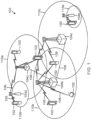
- FIG. 1 illustrates a wireless communication network 100 in accordance with various aspects of the present disclosure.
- the wireless communication network 100 may include a number of UEs 102, as well as a number of base stations 104.
- the base stations 104 may include an evolved Node B (eNodeB).
- eNodeB evolved Node B
- a base station may also be referred to as a base transceiver station, a node B, or an access point.
- a base station 104 may be a station that communicates with the UEs 102 and may also be referred to as a base station, a node B, an access point, and the like.
- the base stations 104 communicate with the UEs 102 as indicated by communication signals 106.
- a UE 102 may communicate with the base station 104 via an uplink and a downlink.
- the downlink (or forward link) refers to the communication link from the base station 104 to the UE 102.
- the uplink (or reverse link) refers to the communication link from the UE 102 to the base station 104.
- the base stations 104 may also communicate with one another, directly or indirectly, over wired and/or wireless connections, as indicated by communication signals 108.
- UEs 102 may be dispersed throughout the wireless network 100, as shown, and each UE 102 may be stationary or mobile.
- the UE 102 may also be referred to as a terminal, a mobile station, a subscriber unit, etc.
- the UE 102 may be a cellular phone, a smartphone, a personal digital assistant, a wireless modem, a laptop computer, a tablet computer, etc.
- the wireless communication network 100 is one example of a network to which various aspects of the disclosure apply.
- Each base station 104 may provide communication coverage for a particular geographic area.
- the term "cell" can refer to this particular geographic coverage area of a base station and/or a base station subsystem serving the coverage area, depending on the context in which the term is used.
- a base station 104 may provide communication coverage for a macro cell, a pico cell, a femto cell, and/or other types of cell.
- a macro cell generally covers a relatively large geographic area (e.g., several kilometers in radius) and may allow unrestricted access by UEs with service subscriptions with the network provider.
- a pico cell would generally cover a relatively smaller geographic area and may allow unrestricted access by UEs with service subscriptions with the network provider.
- a femto cell would also generally cover a relatively small geographic area (e.g., a home) and, in addition to unrestricted access, may also provide restricted access by UEs having an association with the femto cell (e.g., UEs in a closed subscriber group (CSG), UEs for users in the home, and the like).
- a base station for a macro cell may be referred to as a macro base station.
- a base station for a pico cell may be referred to as a pico base station.
- a base station for a femto cell may be referred to as a femto base station or a home base station.
- the base stations 104a, 104b and 104c are examples of macro base station for the coverage areas 1 10a, 110b and 1 10c, respectively.
- the base stations 104d and 104e are examples of pico and/or femto base stations for the coverage areas 110d and 110e, respectively.
- An base station 104 may support one or multiple (e.g., two, three, four, and the like) cells.
- the wireless network 100 may also include relay stations.
- a relay station is a station that receives a transmission of data and/or other information from an upstream station (e.g., a base station, a UE, or the like) and sends a transmission of the data and/or other information to a downstream station (e.g., another UE, another base station, or the like).
- a relay station may also be a UE that relays transmissions for other UEs.
- a relay station may also be referred to as a relay base station, a relay UE, a relay, and the like.
- the wireless network 100 may support synchronous or asynchronous operation.
- the base stations 104 may have similar frame timing, and transmissions from different base stations 104 may be approximately aligned in time.
- the base stations 104 may have different frame timing, and transmissions from different base stations 104 may not be aligned in time.
- the wireless network 100 utilizes orthogonal frequency division multiplexing (OFDM) on the downlink and single-carrier frequency division multiplexing (SC-FDM) on the uplink.
- OFDM and SC-FDM partition the system bandwidth into multiple (K) orthogonal subcarriers, which are also commonly referred to as tones, bins, or the like.
- K orthogonal subcarriers
- Each subcarrier may be modulated with data.
- modulation symbols are sent in the frequency domain with OFDM and in the time domain with SC-FDM.
- the spacing between adjacent subcarriers may be fixed, and the total number of subcarriers (K) may be dependent on the system bandwidth.
- K may be equal to 72, 180, 300, 600, 900, and 1200 for a corresponding system bandwidth of 1.4, 3, 5, 10, 15, or 20 megahertz (MHz), respectively.
- the system bandwidth may also be partitioned into subbands.
- a sub-band may cover 1.08 MHz, and there may be 1, 2, 4, 8 or 16 subbands for a corresponding system bandwidth of 1.4, 3, 5, 10, 15, or 20MHz, respectively.
- FIG. 2 is a block diagram of an exemplary wireless communication device 200 according to embodiments of the present disclosure.
- the wireless communication device 200 may be a base station 104, controller, and/or other network device having any one of many configurations.
- the wireless communication device 200 may include a processor 202, a memory 204 with instructions 206 stored thereon, a multi-RAT carrier aggregation module 208, a first RAT sub-system that includes a transceiver 210a (including a modem 212a and an RF unit 214a) and an antenna 216a, and a second RAT sub-system that includes a transceiver 210b (including a modem 212b and an RF unit 214b) and an antenna 216b.
- These elements may be in direct or indirect communication with each other, for example via one or more buses.
- the processor 202 may include a central processing unit (CPU), a digital signal processor (DSP), an application-specific integrated circuit (ASIC), a controller, a field programmable gate array (FPGA) device, another hardware device, a firmware device, or any combination thereof configured to perform the operations described herein with reference to wireless communication devices 200 introduced above with respect to FIG. 1 and discussed in more detail below.
- the processor 202 may be utilized in combination with the other components of the wireless communication device 200, including the multi-RAT carrier aggregation module 208, to perform the various functions associated with the multi-RAT carrier aggregation, including coordinating control for multiple RATs utilizing a single RAT, as described in greater detail below.
- the processor 202 may also be implemented as a combination of computing devices, e.g., a combination of a DSP and a microprocessor, a plurality of microprocessors, one or more microprocessors in conjunction with a DSP core, or any other such configuration.
- the memory 204 may include a cache memory (e.g., a cache memory of the processor 202), random access memory (RAM), magnetoresistive RAM (MRAM), read-only memory (ROM), programmable read-only memory (PROM), erasable programmable read only memory (EPROM), electrically erasable programmable read only memory (EEPROM), flash memory, solid state memory device, hard disk drives, other forms of volatile and non-volatile memory, or a combination of different types of memory.
- the memory 204 includes a non-transitory computer-readable medium.
- the memory 204 may store instructions 206.
- the instructions 206 may include instructions that, when executed by the processor 202, cause the processor 202 to perform the operations described herein with reference to the wireless communication devices 200 coordinating control for multiple RATs utilizing a single RAT in connection with embodiments of the present disclosure. Instructions 206 may also be referred to as code.
- the terms "instructions” and “code” should be interpreted broadly to include any type of computer-readable statement(s). For example, the terms “instructions” and “code” may refer to one or more programs, routines, sub-routines, functions, procedures, etc. "Instructions" and “code” may include a single computer-readable statement or many computer-readable statements.
- the multi-RAT carrier aggregation module 208 may be used for various aspects of the present disclosure.
- the multi-RAT carrier aggregation module 208 may coordinate the control signaling, scheduling, ACK/NACK, etc. for multiple RATs using communications of a single RAT.
- the multi-RAT carrier aggregation module 208 can utilize communications over one of the first and second RAT sub-systems of the wireless communication device 200 to schedule and/or acknowledge (or not) traffic (e.g., using physical downlink control channel (PDCCH), enhanced physical downlink control channel (ePDCCH), ACK/NACK, etc.) between a UE 102 and the wireless communication device 200 over both the first and second RAT sub-systems.
- PDCCH physical downlink control channel
- ePDCCH enhanced physical downlink control channel
- ACK/NACK etc.
- the multi-RAT carrier aggregation module 308 can use a multi-RAT compatible transmission time interval (TTI) to coordinate the multi-RAT carrier aggregation in some instances.
- TTI transmission time interval
- the transmission time intervals (TTIs), downlink and/or uplink, of the first and second RAT sub-systems can be scaled to one another to allow communications over one of the RAT sub-systems to coordinate communications over both RAT sub-systems.
- the downlink and/or uplink TTIs of the first RAT subsystem can be defined to be the same as, a fraction, and/or a multiple of the corresponding downlink and/or uplink TTIs of the second RAT sub-system.
- the downlink and/or uplink communications over both the first and second RAT sub-systems can be coordinated using only one of the RAT sub-systems.
- the multi-RAT carrier aggregation module 208 can be configured to coordinate communications (downlink and/or uplink) over multiple RATs utilizing a single RAT as described in additional detail with respect to FIGS. 4-9 below.
- wireless communication device 200 is associated with first and second RAT sub-systems.
- the first and second RAT sub-systems may be separate components at a common location (e.g., at the same base station) or at different locations (e.g., at two different base stations, at a base station and a gateway, etc.).
- the wireless communication device 200 may be part of a controller or control system that is in communication with each of the RAT sub-systems, either directly or indirectly, including via wired and/or wireless connections.
- the wireless communication device 200 includes (or is in communication with) additional RAT sub-systems such that the wireless communication device 200 includes (or is in communication with) three or more RAT sub-systems.
- each of the RAT sub-systems includes the transceiver 210a, 210b that may include a modem subsystem 212a, 212a and a radio frequency (RF) unit 214a, 214b.
- the transceiver 210a, 210b can be configured to communicate bi-directionally with other devices, such as UEs 102, base stations 104, and/or other wireless communication devices.
- the modem subsystem 212a, 212b may be configured to modulate and/or encode the data from the multi-RAT carrier aggregation module 208 according to a modulation and coding scheme (MCS), e.g., a low-density parity check (LDPC) coding scheme, a turbo coding scheme, a convolutional coding scheme, etc.
- MCS modulation and coding scheme
- the RF unit 214a, 214b may be configured to process (e.g., perform analog to digital conversion or digital to analog conversion, etc.) modulated/encoded data from the modem subsystem 212a, 212b (on outbound transmissions) or of transmissions originating from another source such as a UE 102, a base station 104, and/or other wireless communication device.
- the modem subsystem 212a, 212b and the RF unit 214a, 214b may be separate devices that are coupled together at the wireless communication device 200 to enable the wireless communication device 200 to communicate with other devices via the respective RAT.
- the RF unit 214a, 214b may provide the modulated and/or processed data, e.g. data packets (or, more generally, data messages that may contain one or more data packets and other information), to the antenna 216a, 216b for transmission to one or more other devices.
- This may include, for example, transmission of control and scheduling signals for multiple RATs utilizing a single RAT according to embodiments of the present disclosure.
- control and scheduling signals for both RAT sub-systems (RAT 1 and RAT 2) of wireless communication device 200 may be coordinated through the first RAT sub-system (RAT 1).
- the antenna 216a, 216b may further receive data messages transmitted from other devices and provide the received data messages for processing and/or demodulation at the transceiver 210a, 210b.
- FIG. 2 illustrates each antenna 216a, 216b as a single antenna, the antenna 216a, 216b may include multiple antennas of similar or different designs in order to sustain multiple transmission links.
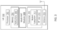
- FIG. 3 is a block diagram of an exemplary UE 102 according to embodiments of the present disclosure.
- the UE 102 is representative of a wide variety of device types, including any one of many configurations described above.
- the UE 102 may include a processor 302, a memory 304 with instructions 306 stored thereon, a multi-RAT module 308, a transceiver 310 (including a modem 312 and an RF unit 314), and an antenna 316. These elements may be in direct or indirect communication with each other, for example via one or more buses.
- the processor 302 may include a central processing unit (CPU), a digital signal processor (DSP), an application-specific integrated circuit (ASIC), a controller, a field programmable gate array (FPGA) device, another hardware device, a firmware device, or any combination thereof configured to perform the operations described herein with reference to UE 102 introduced above with respect to FIG. 1 and discussed in more detail below.
- the processor 302 may be utilized in combination with the other components of the UE 102, including multi-RAT module 308, to perform the various functions associated with the multi-RAT carrier aggregation as described in greater detail below.
- the processor 302 may also be implemented as a combination of computing devices, e.g., a combination of a DSP and a microprocessor, a plurality of microprocessors, one or more microprocessors in conjunction with a DSP core, or any other such configuration.
- the memory 304 may include a cache memory (e.g., a cache memory of the processor 302), random access memory (RAM), magnetoresistive RAM (MRAM), read-only memory (ROM), programmable read-only memory (PROM), erasable programmable read only memory (EPROM), electrically erasable programmable read only memory (EEPROM), flash memory, solid state memory device, hard disk drives, other forms of volatile and non-volatile memory, or a combination of different types of memory.
- the memory 304 includes a non-transitory computer-readable medium.
- the memory 304 may store instructions 306.
- the instructions 306 may include instructions that, when executed by the processor 302, cause the processor 302 to perform the operations described herein with reference to the UE 102 sending (uplink) and/or receiving (downlink) signals utilizing multiple RATs in connection with embodiments of the present disclosure. Instructions 306 may also be referred to as code.
- the terms "instructions” and “code” should be interpreted broadly to include any type of computer-readable statement(s). For example, the terms “instructions” and “code” may refer to one or more programs, routines, sub-routines, functions, procedures, etc. "Instructions" and “code” may include a single computer-readable statement or many computer-readable statements.
- the multi-RAT module 308 may be used for various aspects of the present disclosure.
- the multi-RAT module 308 may coordinate the control signaling, scheduling, ACK/NACK, etc. for multiple RATs using a single RAT.
- the multi-RAT module 308 can utilize communications over one RAT sub-system (e.g., RAT 1 of the wireless communication device 200 of FIG. 2 ) to schedule and/or acknowledge (or not) traffic (e.g., using physical downlink control channel (PDCCH), enhanced physical downlink control channel (ePDCCH), ACK/NACK, etc.) between the UE 102 and other wireless communication device(s) over multiple RAT sub-systems (e.g., RAT 1 and RAT 2 of the wireless communication device 200 of FIG. 2 ).
- RAT sub-system e.g., RAT 1 of the wireless communication device 200 of FIG. 2
- the multi-RAT module 308 can use a multi-RAT compatible transmission time interval (TTI) to coordinate the multi-RAT carrier aggregation in some instances.
- TTI transmission time interval
- the transmission time intervals (TTIs), downlink and/or uplink, of the multiple RATs can be scaled to one another to allow communications over one of the RATs to be utilized to coordinate communications over the other RATs.
- the downlink and/or uplink TTIs of the first RAT can be defined to be the same as, a fraction, and/or a multiple of the corresponding downlink and/or uplink TTIs of another RAT.
- the downlink and/or uplink communications over both RATs can be coordinated using only one of the RAT sub-systems.
- the multi-RAT module 308 can be configured to coordinate communications (downlink and/or uplink) over multiple RATs utilizing control, scheduling, and/or ACK/NACK communications using a single RAT as described in additional detail with respect to FIGS. 4-9 below.
- the transceiver 310 may include the modem subsystem 312 and the radio frequency (RF) unit 314.
- the transceiver 310 can be configured to communicate bi-directionally with other devices, such as base stations 104 and/or other UEs 102.
- the modem subsystem 312 may be configured to modulate and/or encode the data from the multi-RAT module 308 according to a modulation and coding scheme (MCS), e.g., a low-density parity check (LDPC) coding scheme, a turbo coding scheme, a convolutional coding scheme, etc.
- MCS modulation and coding scheme
- LDPC low-density parity check
- the RF unit 314 may be configured to process (e.g., perform analog to digital conversion or digital to analog conversion, etc.) modulated/encoded data from the modem subsystem 312 (on outbound transmissions) or of transmissions originating from another source such as a base station 104 or another UE 102. Although shown as integrated together in transceiver 310, the modem subsystem 312 and the RF unit 314 may be separate devices that are coupled together at the UE 102 to enable the UE 102 to communicate with other devices.
- process e.g., perform analog to digital conversion or digital to analog conversion, etc.
- the RF unit 314 may provide the modulated and/or processed data, e.g. data packets (or, more generally, data messages that may contain one or more data packets and other information), to the antenna 316 for transmission to one or more other devices. This may include, for example, transmission of control signals, data signals, ACK/NACK signals, etc. to other devices according to embodiments of the present disclosure.
- the antenna 316 may further receive data, including control signals, data signals, ACK/NACK signals, etc., transmitted from other devices and provide the received data for processing and/or demodulation at the transceiver 310.
- FIG. 3 illustrates antenna 316 as a single antenna, antenna 316 may include multiple antennas of similar or different designs in order to sustain multiple transmission links.
- the UE 102 includes multiple antennas such that each RAT has a dedicated antenna. Further, in some implementations, a single antenna can be utilized for multiple RATs.
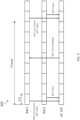
- Figs. 4-6 shown therein are various frame format and corresponding communication transmissions between a first radio access technology component, a second radio access technology component, and a user equipment in accordance with various aspects of the present disclosure.
- Figs. 4-6 illustrate various approaches to coordinating transmission time intervals (TTIs) across multiple RATs to facilitate multi-RAT carrier aggregation for downlink transmissions in accordance with the present disclosure.
- TTIs transmission time intervals
- control information for communications over both RAT 1 and RAT 2 are sent to the UE 120 utilizing RAT 1 only.
- the control information can include information regarding a channel condition (e.g. channel quality information (CQI)), a downlink band(s), coding scheme(s), scheduling/timing of a data load to be transmitted to the UE 120, a size of a data load to be transmitted to the UE 120, etc.
- CQI channel quality information
- the UE 120 utilizes the received control information to configure itself for the receipt of data over RAT 2 and/or RAT 1.
- data may be transmitted over one or both of RAT 1 and RAT 2.
- data may only be transmitted over one of RAT 1 or RAT 2.
- data may be transmitted over both RAT 1 and RAT 2.
- the data sent over each RAT may be different data or the same data (e.g., where the data is transmitted over both RATs in an effort to ensure receipt by the UE 120).
- both RAT 1 data and RAT 2 are transmitted to the UE 120.
- the RAT 1 data transmitted to the UE 120 can be transmitted using a different channel of RAT 1 (e.g., a data channel) than the channel (e.g., a control channel) used to transmit the control information for RAT 1 and RAT 2.
- the UE 120 transmits an acknowledgement (ACK) or negative acknowledgement (NACK) using RAT 1 in a subsequent TTI.
- the ACK/NACK transmitted by the UE 120 can be transmitted using the channel (e.g., a control channel) used to transmit the control information for RAT 1 and RAT 2 to the UE 120, which may be different than the channel of RAT 1 (e.g., a data channel) that the RAT 1 data was transmitted over.
- the ACK/NACK provides an indication as to whether the UE 120 successfully received the data transmitted over RAT 1 and/or RAT 2. In some instances, a separate ACK/NACK is sent with respect to each of the RAT 1 data and the RAT 2 data, but each ACK/NACK is sent using RAT 1.
- a single ACK/NACK is sent that indicates that the RAT 1 data and/or RAT 2 data was received by the UE 120, or not.
- the UE 120 does not make a separate ACK/NACK transmission using RAT 2. Rather, the ACK/NACK transmitted by the UE 120 using RAT 1 includes an indication as to whether the RAT 2 data was received or not.
- a base station, controller, control system, and/or other component(s) linking RAT 1 and RAT 2 may communicate the ACK/NACK received via RAT 1 to RAT 2 and/or otherwise instruct RAT 2 based on the received ACK/NACK.
- the RAT 2 data can be retransmitted to the UE 120 (e.g., using a HARQ or similar approach) via RAT 2.
- RAT 2 does not need to receive the ACK/NACK from the UE 120
- the RAT 2 can continue operating in the same operation mode without switching.
- RAT 2 may continue operating in a downlink mode (e.g., by sending data to other UEs) during the TTI in which the UE 120 sends the ACK/NACK.
- the spacing between the TTI in which the control information and data are transmitted to the UE 120, the TTI in which the UE 120 sends the ACK/NACK, and the next TTI in which the control information and data are retransmitted can vary depending on the particular RATs being utilized, whether the structure needs to be backward compatible (or not), desired/available processing times and/or power, hardware (e.g., base station, UE, etc.) features, and/or other network parameters.
- the TTI structure of RAT 2 is scaled to the TTI structure (or slot structure) of RAT 1 to facilitate the multi-RAT carrier aggregation of the present disclosure.
- RAT 1 may be considered a legacy or existing RAT of a wireless network, where RAT 2 is a newly added or introduced RAT to the wireless network.
- RAT 1 may be an LTE RAT and RAT 2 may be a RAT having increased bandwidth and/or throughput relative to the LTE RAT, a RAT having an unlicensed band, and/or a RAT having other features different than the LTE RAT.
- the TTI of RAT 2 is scaled to the 1 ms TTI structures and/or 500 ⁇ s slot structures associated with current LTE frame structures to facilitate the multi-RAT carrier aggregation of the present disclosure.
- the processing time(s) of RAT 2 e.g., HARQ latency
- each of Figs. 4-6 shows a different frame structure spacing according to aspects of the present disclosure.
- the examples show the timing of the frame structures of the second RATs being aligned to the timing of the frame structures of the first RATs.
- the frame structure 400 of Fig. 4 illustrates an approach where the ACK/NACK is sent at TTI n +4 following receipt of the control information and/or data at TTI n and the retransmission occurs at TTI n +8 in the event that a NACK is sent by the UE 120.
- the frame structure 500 of Fig. 5 illustrates an approach where the ACK/NACK is sent at TTI n +2 following receipt of the control information and/or data at TTI n and the retransmission occurs at TTI n +4 in the event that a NACK is sent by the UE 120.
- the frame structure 500 of Fig. 5 has a reduced processing time or HARQ latency as compared to Fig. 4 . This reduced processing time can be advantageous for increasing throughput of the network.
- such an approach may require changing standards and/or default rules associated with an existing RAT deployment (e.g., RAT 1, an LTE RAT, etc.).
- the frame structure 600 of Fig. 6 has a further reduced processing time or HARQ latency as compared to Figs. 4 and 5 .
- the coordinated timing of the different RATs can be scheduled using slots of the TTIs.
- each TTI may be divided up into any number of slots, including 2, 3, 4, or more slots. In the illustrated embodiment of Fig. 6 , each TTI has been divided into two slots.
- Fig. 7 shown therein is a protocol diagram 700 illustrating transmissions between a base station 110 having first and second radio access technology components and a user equipment 120 in accordance with various aspects of the present disclosure.
- Fig. 7 illustrates transmissions consistent with those described above in the context of Figs. 4-6 for downlink, multi-RAT carrier aggregation.
- the base station 110 transmits control information for communications over both RAT 1 and RAT 2 to the UE 120 utilizing RAT 1 only.
- the control information can include information regarding a channel condition (e.g.
- the UE 120 utilizes the received control information to configure itself for the receipt of data over RAT 2 and/or RAT 1.
- data may be transmitted by the base station 110 over one or both of RAT 1 and RAT 2.
- RAT 1 RAT 1
- RAT 2 RAT 2
- the base station 110 may select a particular RAT (RAT 1 or RAT 2) to transmit data over.
- the base station 110 may transmit data over both RAT 1 and RAT 2.
- the base station 110 can transmit the RAT 1 data to the UE 120 using a different channel of RAT 1 (e.g., a data channel) than the channel (e.g., a control channel) used to transmit the control information for RAT 1 and RAT 2.
- a different channel of RAT 1 e.g., a data channel
- the channel e.g., a control channel
- the UE 120 subsequently transmits an acknowledgement (ACK) or negative acknowledgement (NACK) using RAT 1.
- the UE 120 can transmit the ACK/NACK using the channel (e.g., a control channel) used by the base station 110 to transmit the control information for RAT 1 and RAT 2 to the UE 120, which may be different than the channel of RAT 1 (e.g., a data channel) that the RAT 1 data was received over.
- the ACK/NACK provides an indication as to whether the UE 120 successfully received the data transmitted over RAT 1 and/or RAT 2.
- the UE 120 sends a separate ACK/NACK for each of the RAT 1 data and the RAT 2 data, but each ACK/NACK is sent using RAT 1.
- the UE 120 sends a single ACK/NACK that indicates whether the RAT 1 data and/or RAT 2 data was received by the UE 120, or not.
- the UE 120 does not make a separate ACK/NACK transmission using RAT 2.
- the ACK/NACK transmitted by the UE 120 using RAT 1 includes an indication as to whether the RAT 2 data was received or not.
- a base station 110 (or a controller, control system, and/or other component(s) linking RAT 1 and RAT 2 of the base station 110) may communicate the ACK/NACK received via RAT 1 to RAT 2 and/or otherwise instruct RAT 2 based on the received ACK/NACK from UE 120. As shown, this process repeats to facilitate continued communication between the base station 110 and the UE 120 using a multi-RAT carrier aggregation scheme.
- Fig. 8 shown therein is an exemplary frame format 800 and corresponding communication transmissions between a first radio access technology component, a second radio access technology component, and a user equipment in accordance with various aspects of the present disclosure.
- Figs. 8 illustrates an approach to coordinating transmission time intervals (TTIs) across multiple RATs to facilitate multi-RAT carrier aggregation for uplink transmissions in accordance with the present disclosure.
- TTIs transmission time intervals
- control information for uplink communications over both RAT 1 and RAT 2 are sent to the UE 120 utilizing RAT 1 only.
- the control information can include information regarding a channel condition (e.g. channel quality information (CQI)), a downlink band(s), coding scheme(s), scheduling/timing of a data uplink, etc.
- CQI channel quality information
- the UE 120 utilizes the received control information to configure itself for the transmission of data over RAT 2 and/or RAT 1 in a subsequent TTI in the illustrated embodiment.
- the UE 120 may transmit data over one or both of RAT 1 and RAT 2. For example, particularly types of data may be more suitable for transmission using a particular RAT.
- the UE 120 may only transmit data over one of RAT 1 or RAT 2. In other instances, data may be transmitted over both RAT 1 and RAT 2. When data is transmitted over both RAT 1 and RAT 2, the data sent over each RAT may be different data or the same data (e.g., where the data is transmitted over both RATs by the UE 120 in an effort to ensure receipt). In the illustrated embodiment, both RAT 1 data and RAT 2 are transmitted by the UE 120.
- the RAT 1 data transmitted by the UE 120 can be transmitted using a different channel of RAT 1 (e.g., a data channel) than the channel (e.g., a control channel) used to transmit the control information for RAT 1 and RAT 2 to the UE 120.
- a different channel of RAT 1 e.g., a data channel
- the channel e.g., a control channel
- RAT 1 transmits an acknowledgement (ACK) or negative acknowledgement (NACK) using RAT 1 in a subsequent TTI.
- the ACK/NACK transmitted by RAT 1 can be transmitted using the channel (e.g., a control channel) used to transmit the initial uplink control information for RAT 1 and RAT 2 to the UE 120, which may be different than the channel of RAT 1 (e.g., a data channel) that the RAT 1 data was transmitted over by the UE 120.
- the ACK/NACK provides an indication as to whether the RAT 1 (or associated wireless communication device) successfully received the data transmitted over RAT 1 and/or RAT 2.
- a separate ACK/NACK is sent with respect to each of the RAT 1 data and the RAT 2 data, but each ACK/NACK is sent using RAT 1.
- a single ACK/NACK is sent that indicates that the RAT 1 data and/or RAT 2 data was received, or not.
- a separate ACK/NACK transmission is not made using RAT 2. Rather, the ACK/NACK transmitted using RAT 1 includes an indication as to whether the RAT 2 data was received or not.
- the RAT 1 can also transmit control information for uplink communications over both RAT 1 and RAT 2, which may be the same or updated as the initially transmitted control information.
- the ACK/NACK and updated control information are sent in the same slot of a common TTI. Accordingly, if a NACK is received by the UE 120, then the UE 120 can attempt to retransmit the data based on the updated control information received along with the NACK.
- hardware e.g., base station, UE, etc.
- Fig. 8 illustrates a slot-based approach similar to Fig. 6 , but it is understood that various other approaches may be utilized, including approaches similar to those described above with respect to Figs. 4 and 5 , for uplink multi-RAT carrier aggregation techniques in accordance with the present disclosure.
- Fig. 9 shown therein is a protocol diagram 900 illustrating transmissions between a base station 110 having first and second radio access technology components and a user equipment 120 in accordance with various aspects of the present disclosure.
- Fig. 9 illustrates transmissions consistent with those described above in the context of Fig. 8 for uplink, multi-RAT carrier aggregation.
- the base station 110 transmits control information for communications over both RAT 1 and RAT 2 to the UE 120 utilizing RAT 1 only.
- the control information can include information regarding a channel condition (e.g. channel quality information (CQI)), a downlink band(s), coding scheme(s), scheduling/timing of uplink data, etc.
- CQI channel quality information
- the UE 120 utilizes the received control information to configure itself for the transmission of data over RAT 2 and/or RAT 1.
- uplink data may be transmitted by the UE 120 over one or both of RAT 1 and RAT 2.
- particularly types of data may be more suitable for transmission using a particular RAT.
- the UE 120 may select a particular RAT (RAT 1 or RAT 2) to transmit data over.
- the UE 120 may transmit data over both RAT 1 and RAT 2.
- the UE 120 can transmit the RAT 1 data to the base station 110 using a different channel of RAT 1 (e.g., a data channel) than the channel (e.g., a control channel) used to transmit the control information for RAT 1 and RAT 2 to the UE 120.
- a different channel of RAT 1 e.g., a data channel
- the channel e.g., a control channel
- the base station 120 subsequently transmits, using RAT 1, an acknowledgement (ACK) or negative acknowledgement (NACK) and updated control information.
- the base station 110 can transmit the ACK/NACK using the channel (e.g., a control channel) used to transmit the initial control information for RAT 1 and RAT 2 to the UE 120, which may be different than the channel of RAT 1 (e.g., a data channel) that the RAT 1 data was transmitted over by UE 120.
- the ACK/NACK provides an indication as to whether the base station 110 successfully received the data transmitted over RAT 1 and/or RAT 2.
- the base station 110 sends a separate ACK/NACK for each of the RAT 1 data and the RAT 2 data, but each ACK/NACK is sent using RAT 1. In other instances, the base station 110 sends a single ACK/NACK that indicates whether the RAT 1 data and/or RAT 2 data was received by the base station 110, or not. The base station 110 does not make a separate ACK/NACK transmission using RAT 2. Rather, the ACK/NACK transmitted by the base station 110 using RAT 1 includes an indication as to whether the RAT 2 data was received or not. As shown, this process repeats to facilitate continued communication between the base station 110 and the UE 120 using a multi-RAT carrier aggregation scheme.
- the base station 110 and the UE 120 may periodically, randomly, or based on demand alternate between the uplink multi-RAT carrier aggregation approach illustrated in Fig. 9 , the downlink multi-RAT carrier aggregation approach illustrated in Fig. 7 , and/or standard uplink and downlink communication approaches.
- Information and signals may be represented using any of a variety of different technologies and techniques.
- data, instructions, commands, information, signals, bits, symbols, and chips that may be referenced throughout the above description may be represented by voltages, currents, electromagnetic waves, magnetic fields or particles, optical fields or particles, or any combination thereof.
- a general-purpose processor may be a microprocessor, but in the alternative, the processor may be any conventional processor, controller, microcontroller, or state machine.
- a processor may also be implemented as a combination of computing devices (e.g., a combination of a DSP and a microprocessor, multiple microprocessors, one or more microprocessors in conjunction with a DSP core, or any other such configuration).
- the functions described herein may be implemented in hardware, software executed by a processor, firmware, or any combination thereof. If implemented in software executed by a processor, the functions may be stored on or transmitted over as one or more instructions or code on a computer-readable medium. Other examples and implementations are within the scope of the disclosure and appended claims. For example, due to the nature of software, functions described above can be implemented using software executed by a processor, hardware, firmware, hardwiring, or combinations of any of these. Features implementing functions may also be physically located at various positions, including being distributed such that portions of functions are implemented at different physical locations.
- Embodiments of the present disclosure include a computer-readable medium having program code recorded thereon, the program code comprising code for causing a computer, at a first wireless communication device, to transmit control information to a second wireless communication device via a first radio access technology (RAT), the control information including control information for a second RAT.
- the program code further comprises code for causing the computer to receive an acknowledgement (ACK) or negative acknowledgement (NACK) from the second wireless communication device via the first RAT, the ACK or NACK being related to communications of the second wireless communication device conducted via the second RAT.
- ACK acknowledgement
- NACK negative acknowledgement
- the computer-readable medium further includes wherein the control information further includes control information for the first RAT.
- the computer-readable medium further includes code for causing the computer to transmit first data to the second wireless communication device via the first RAT.
- the computer-readable medium further includes code for causing the computer to transmit second data to the second wireless communication device via the second RAT.
- the computer-readable medium further includes code for causing the computer to retransmit the second data to the second wireless communication device via the second RAT if the NACK is received from the second wireless communication device via the first RAT.
- the computer-readable medium further includes wherein the first RAT includes a long term evolution (LTE) RAT.
- LTE long term evolution
- the computer-readable medium further includes wherein the code for causing the computer to transmit the control information causes the control information to be transmitted to the second wireless communication device via the LTE RAT during a first transmission time interval (TTI), the code for causing the computer to transmit the second data causes the second data to be transmitted to the second wireless communication device via the second RAT during the first TTI, and the code for causing the computer to receive the ACK or the NACK causes the ACK or the NACK to be received from the second wireless communication device during a second TTI.
- the computer-readable medium further includes wherein the first wireless communication device is a base station and the second wireless communication device is a user equipment.
- the computer-readable medium further includes wherein the first wireless communication device includes an antenna associated with the second RAT.
- the computer-readable medium further includes wherein the first wireless communication device is in communication with an antenna associated with the second RAT positioned remote from the first wireless communication device.
- Embodiments of the present disclosure further include a computer-readable medium having program code recorded thereon, the program code comprising code for causing a computer, at a first wireless communication device, to receive control information from a second wireless communication device via a first radio access technology (RAT), the control information including control information for a second RAT.
- the computer-readable medium further includes code for causing the computer to transmit first data to the second wireless communication device via the second RAT.
- the computer-readable medium further includes code for causing the computer to receive an acknowledgement (ACK) or negative acknowledgement (NACK) from the second wireless communication device via the first RAT, the ACK or NACK indicating whether the first data was received by the second wireless communication device via the second RAT.
- the computer-readable medium further includes code for causing the computer to retransmit the first data to the second wireless communication device via the second RAT if the NACK is received from the second wireless communication device via the first RAT.
- the computer-readable medium further includes wherein the control information further includes control information for the first RAT.
- the computer-readable medium further includes code for causing the computer to transmit second data to the second wireless communication device via the first RAT.
- the computer-readable medium further includes wherein the first RAT includes a long term evolution (LTE) RAT.
- the computer-readable medium further includes wherein the code for causing the computer to receive the control information causes the control information to be received at the first wireless communication device via the LTE RAT during a first transmission time interval (TTI), and the code for causing the computer to transmit the first data causes the first data to be transmitted to the second wireless communication device via the second RAT during a second TTI.
- TTI transmission time interval
- the computer-readable medium further includes wherein the first wireless communication device is a user equipment and the second wireless communication device is a base station.
- the computer-readable medium further includes wherein the code for causing the computer to transmit the first data to the second wireless communication device via the second RAT causes the first data to be transmitted to an antenna of the second wireless communication device associated with the second RAT.
- the computer-readable medium further includes wherein the code for causing the computer to transmit the first data to the second wireless communication device via the second RAT causes the first data to be transmitted to an antenna associated with the second RAT positioned remote from the second wireless communication device.
- Embodiments of the present disclosure further include a wireless communications device comprising means for transmitting control information to a second wireless communication device via a first radio access technology (RAT), the control information including control information for a second RAT.
- the wireless communications device further comprises means for receiving an acknowledgement (ACK) or negative acknowledgement (NACK) from the second wireless communication device via the first RAT, the ACK or NACK being related to communications of the second wireless communication device conducted via the second RAT.
- ACK acknowledgement
- NACK negative acknowledgement
- the wireless communications device further includes wherein the control information further includes control information for the first RAT.
- the wireless communications device further includes means for transmitting first data to the second wireless communication device via the first RAT.
- the wireless communications device further includes means for transmitting second data to the second wireless communication device via the second RAT.
- the wireless communications device further includes means for retransmitting the second data to the second wireless communication device via the second RAT if the NACK is received from the second wireless communication device via the first RAT.
- the wireless communications device further includes wherein the first RAT includes a long term evolution (LTE) RAT.
- LTE long term evolution
- the wireless communications device further includes wherein the means for transmitting the control information is configured to transmit the control information to the second wireless communication device via the LTE RAT during a first transmission time interval (TTI), the means for transmitting the second data is configured to transmit the second data to the second wireless communication device via the second RAT during the first TTI, and the means for receiving the ACK or the NACK is configured to receive the ACK or the NACK from the second wireless communication device during a second TTI.
- the wireless communications device further includes wherein the wireless communication device is a base station and the second wireless communication device is a user equipment.
- the wireless communications device further includes an antenna associated with the second RAT.
- the wireless communications device further includes wherein the wireless communication device is in communication with an antenna associated with the second RAT positioned remote from the wireless communication device.
- Embodiments of the present disclosure further include a wireless communications device comprising means for receiving control information from a second wireless communication device via a first radio access technology (RAT), the control information including control information for a second RAT.
- the wireless communications device further comprises means for transmitting first data to the second wireless communication device via the second RAT.
- RAT radio access technology
- the wireless communications device further includes means for receiving an acknowledgement (ACK) or negative acknowledgement (NACK) from the second wireless communication device via the first RAT, the ACK or NACK indicating whether the first data was received by the second wireless communication device via the second RAT.
- the wireless communications device further includes means for retransmitting the first data to the second wireless communication device via the second RAT if the NACK is received from the second wireless communication device via the first RAT.
- the wireless communications device further includes wherein the control information further includes control information for the first RAT.
- the wireless communications device further includes means for transmitting second data to the second wireless communication device via the first RAT.
- the wireless communications device further includes wherein the first RAT includes a long term evolution (LTE) RAT.
- LTE long term evolution
- the wireless communications device further includes wherein the means for receiving the control information is configured to receive the control information via the LTE RAT during a first transmission time interval (TTI), and the means for transmitting the first data is configured to transmit the first data via the second RAT during a second TTI.
- the wireless communications device further includes wherein the wireless communication device is a user equipment and the second wireless communication device is a base station.
- the wireless communications device further includes wherein the means for transmitting the first data to the second wireless communication device via the second RAT is configured to transmit the first data to an antenna of the second wireless communication device associated with the second RAT.
- the wireless communications device further includes wherein the means for transmitting the first data to the second wireless communication device via the second RAT is configured to an antenna associated with the second RAT positioned remote from the second wireless communication device.
Landscapes
- Engineering & Computer Science (AREA)
- Signal Processing (AREA)
- Computer Networks & Wireless Communication (AREA)
- Mobile Radio Communication Systems (AREA)
- Catching Or Destruction (AREA)
Applications Claiming Priority (3)
| Application Number | Priority Date | Filing Date | Title |
|---|---|---|---|
| US201562133367P | 2015-03-14 | 2015-03-14 | |
| US15/068,374 US10028176B2 (en) | 2015-03-14 | 2016-03-11 | Carrier aggregation across different radio access technologies |
| PCT/US2016/022346 WO2016149202A1 (en) | 2015-03-14 | 2016-03-14 | Carrier aggregation across different radio access technologies |
Publications (3)
| Publication Number | Publication Date |
|---|---|
| EP3272049A1 EP3272049A1 (en) | 2018-01-24 |
| EP3272049C0 EP3272049C0 (en) | 2024-04-10 |
| EP3272049B1 true EP3272049B1 (en) | 2024-04-10 |
Family
ID=56888740
Family Applications (1)
| Application Number | Title | Priority Date | Filing Date |
|---|---|---|---|
| EP16716083.7A Active EP3272049B1 (en) | 2015-03-14 | 2016-03-14 | Carrier aggregation across different radio access technologies |
Country Status (6)
| Country | Link |
|---|---|
| US (2) | US10028176B2 (https=) |
| EP (1) | EP3272049B1 (https=) |
| JP (2) | JP6482675B2 (https=) |
| KR (2) | KR101943252B1 (https=) |
| CN (2) | CN107409022B (https=) |
| WO (1) | WO2016149202A1 (https=) |
Families Citing this family (41)
| Publication number | Priority date | Publication date | Assignee | Title |
|---|---|---|---|---|
| EP2966797B1 (en) * | 2011-03-15 | 2018-06-13 | Telefonaktiebolaget LM Ericsson (publ) | Methods and devices for determining timing of feedback information |
| CN102833802B (zh) * | 2012-08-15 | 2015-09-23 | 电信科学技术研究院 | 一种数据转发方法及设备 |
| US10028176B2 (en) | 2015-03-14 | 2018-07-17 | Qualcomm Incorporated | Carrier aggregation across different radio access technologies |
| US10517021B2 (en) | 2016-06-30 | 2019-12-24 | Evolve Cellular Inc. | Long term evolution-primary WiFi (LTE-PW) |
| US10727991B2 (en) | 2016-09-22 | 2020-07-28 | Qualcomm Incorporated | Integrating LTE and new radio |
| JP6915335B2 (ja) * | 2017-03-23 | 2021-08-04 | ソニーグループ株式会社 | 通信装置、通信方法、及びプログラム |
| CN109412760B (zh) * | 2017-08-18 | 2021-11-26 | 中国电信股份有限公司 | 上行反馈方法、装置和计算机可读存储介质 |
| US10506621B2 (en) * | 2017-11-30 | 2019-12-10 | Qualcomm Incorporated | Uplink sharing in a multiple radio access technology environment |
| US10455429B2 (en) | 2018-03-09 | 2019-10-22 | Google Llc | Inter-radio access technology spectrum sharing |
| JP7307320B2 (ja) * | 2019-04-25 | 2023-07-12 | 株式会社三洋物産 | 遊技機 |
| JP7272095B2 (ja) * | 2019-04-25 | 2023-05-12 | 株式会社三洋物産 | 遊技機 |
| JP7272092B2 (ja) * | 2019-04-25 | 2023-05-12 | 株式会社三洋物産 | 遊技機 |
| JP7272093B2 (ja) * | 2019-04-25 | 2023-05-12 | 株式会社三洋物産 | 遊技機 |
| JP7275908B2 (ja) * | 2019-06-27 | 2023-05-18 | 株式会社三洋物産 | 遊技機 |
| JP7275916B2 (ja) * | 2019-06-27 | 2023-05-18 | 株式会社三洋物産 | 遊技機 |
| JP7275914B2 (ja) * | 2019-06-27 | 2023-05-18 | 株式会社三洋物産 | 遊技機 |
| JP7275913B2 (ja) * | 2019-06-27 | 2023-05-18 | 株式会社三洋物産 | 遊技機 |
| JP7275909B2 (ja) * | 2019-06-27 | 2023-05-18 | 株式会社三洋物産 | 遊技機 |
| JP7275911B2 (ja) * | 2019-06-27 | 2023-05-18 | 株式会社三洋物産 | 遊技機 |
| JP7275910B2 (ja) * | 2019-06-27 | 2023-05-18 | 株式会社三洋物産 | 遊技機 |
| JP7275912B2 (ja) * | 2019-06-27 | 2023-05-18 | 株式会社三洋物産 | 遊技機 |
| JP7275915B2 (ja) * | 2019-06-27 | 2023-05-18 | 株式会社三洋物産 | 遊技機 |
| JP7302377B2 (ja) * | 2019-08-22 | 2023-07-04 | 株式会社三洋物産 | 遊技機 |
| JP7307330B2 (ja) * | 2019-08-22 | 2023-07-12 | 株式会社三洋物産 | 遊技機 |
| JP7302374B2 (ja) * | 2019-08-22 | 2023-07-04 | 株式会社三洋物産 | 遊技機 |
| JP7302378B2 (ja) * | 2019-08-22 | 2023-07-04 | 株式会社三洋物産 | 遊技機 |
| JP7302375B2 (ja) * | 2019-08-22 | 2023-07-04 | 株式会社三洋物産 | 遊技機 |
| JP7302372B2 (ja) * | 2019-08-22 | 2023-07-04 | 株式会社三洋物産 | 遊技機 |
| JP7302376B2 (ja) * | 2019-08-22 | 2023-07-04 | 株式会社三洋物産 | 遊技機 |
| JP7302373B2 (ja) * | 2019-08-22 | 2023-07-04 | 株式会社三洋物産 | 遊技機 |
| JP7302379B2 (ja) * | 2019-08-23 | 2023-07-04 | 株式会社三洋物産 | 遊技機 |
| JP7307331B2 (ja) * | 2019-08-23 | 2023-07-12 | 株式会社三洋物産 | 遊技機 |
| JP7342587B2 (ja) * | 2019-10-03 | 2023-09-12 | 株式会社三洋物産 | 遊技機 |
| JP7342589B2 (ja) * | 2019-10-03 | 2023-09-12 | 株式会社三洋物産 | 遊技機 |
| JP7342588B2 (ja) * | 2019-10-03 | 2023-09-12 | 株式会社三洋物産 | 遊技機 |
| JP7342585B2 (ja) * | 2019-10-03 | 2023-09-12 | 株式会社三洋物産 | 遊技機 |
| JP7342586B2 (ja) * | 2019-10-03 | 2023-09-12 | 株式会社三洋物産 | 遊技機 |
| JP7342584B2 (ja) * | 2019-10-03 | 2023-09-12 | 株式会社三洋物産 | 遊技機 |
| CN115276925A (zh) * | 2021-04-30 | 2022-11-01 | 华为技术有限公司 | 一种通信方法及装置 |
| US11985093B2 (en) * | 2021-11-19 | 2024-05-14 | Qualcomm Incorporated | Feedback design for network coded transmissions in wireless communication network |
| EP4466919A4 (en) * | 2022-01-21 | 2025-09-10 | Qualcomm Inc | INTER-COMMUNICATION TECHNOLOGY AGGREGATION OF ASYNCHRONOUS RADIO FREQUENCY AND VISIBLE LIGHT COMMUNICATION LINKS |
Family Cites Families (43)
| Publication number | Priority date | Publication date | Assignee | Title |
|---|---|---|---|---|
| JP2006115156A (ja) * | 2004-10-14 | 2006-04-27 | Matsushita Electric Ind Co Ltd | アクセスポイント、アクセスポイント制御装置および無線lanシステム |
| KR101648584B1 (ko) * | 2008-10-15 | 2016-09-02 | 엘지전자 주식회사 | 다중 반송파 시스템에서 harq 수행 방법 |
| US20100234071A1 (en) * | 2009-03-12 | 2010-09-16 | Comsys Communication & Signal Processing Ltd. | Vehicle integrated communications system |
| US9112575B2 (en) * | 2009-03-12 | 2015-08-18 | Futurewei Technologies, Inc. | System and method for smart relay operation in a wireless communications system |
| US9432991B2 (en) * | 2009-04-21 | 2016-08-30 | Qualcomm Incorporated | Enabling support for transparent relays in wireless communication |
| US8340676B2 (en) * | 2009-06-25 | 2012-12-25 | Motorola Mobility Llc | Control and data signaling in heterogeneous wireless communication networks |
| US20110134831A1 (en) * | 2009-12-03 | 2011-06-09 | Nokia Corporation | Architecture Providing Multi-System Carrier Aggregation |
| US8483156B2 (en) * | 2010-05-03 | 2013-07-09 | Nokia Siemens Networks Oy | Feedback for inter-radio access technology carrier aggregation |
| US20110269453A1 (en) * | 2010-05-03 | 2011-11-03 | Nokia Siemens Networks Oy | Apparatus and method for inter-radio access technology carrier aggregation mobility enhancement |
| US8498666B2 (en) * | 2010-05-05 | 2013-07-30 | Nokia Siemens Networks Oy | Carrier aggregation for two radio systems |
| US8804616B2 (en) * | 2010-06-15 | 2014-08-12 | Telefonaktiebolaget Lm Ericsson (Publ) | Signaling mechanism for inter-RAT carrier aggregation |
| WO2012038117A1 (en) * | 2010-09-20 | 2012-03-29 | Nokia Siemens Networks Oy | Discontinuous reception across transmissions on different radio access technologies |
| US8837358B2 (en) * | 2010-10-18 | 2014-09-16 | Nokia Siemens Networks Oy | UL ACK/NACK for inter-radio access technology carrier aggregation |
| CN102457924B (zh) * | 2010-10-21 | 2014-12-03 | 华为技术有限公司 | 一种多载波的切换方法和装置 |
| US8989025B2 (en) * | 2010-11-12 | 2015-03-24 | Telefonaktiebolaget L M Ericsson (Publ) | UE timing adjustment in a multi-RAT, carrier aggregation community system |
| FI3319395T3 (fi) * | 2010-12-03 | 2023-08-01 | Interdigital Patent Holdings Inc | Menetelmä ja laite moniradioliityntätekniikan kantoaaltojen yhdistämisen suorittamiseksi |
| EP3226459B1 (en) * | 2010-12-13 | 2020-11-25 | Telefonaktiebolaget LM Ericsson (publ) | Exchange of parameters relating to measurement periods |
| TWI615043B (zh) * | 2011-02-07 | 2018-02-11 | 內數位專利控股公司 | 在免頻譜執照中操作補充胞元方法及裝置 |
| WO2012112112A1 (en) * | 2011-02-15 | 2012-08-23 | Telefonaktiebolaget Lm Ericsson (Publ) | A first network node and a second network node and methods therein |
| WO2012122170A1 (en) * | 2011-03-07 | 2012-09-13 | Interdigital Patent Holdings, Inc. | Method and apparatus for sending uplink control information for multi-radio access technology operation |
| EP2966797B1 (en) * | 2011-03-15 | 2018-06-13 | Telefonaktiebolaget LM Ericsson (publ) | Methods and devices for determining timing of feedback information |
| KR101600487B1 (ko) | 2011-04-18 | 2016-03-21 | 엘지전자 주식회사 | 무선통신시스템에서 신호 전송 방법 및 장치 |
| EP2719218B1 (en) * | 2011-06-08 | 2015-07-08 | Telefonaktiebolaget LM Ericsson (PUBL) | Methods and devices for reporting a downlink channel quality |
| US8711740B2 (en) * | 2011-06-23 | 2014-04-29 | Qualcomm Incorporated | Multi-radio coexistence |
| CN103636251B (zh) * | 2011-06-29 | 2017-12-08 | 诺基亚技术有限公司 | 用于多无线电接入技术环境中终端测量配置的方法和装置 |
| US9537633B2 (en) | 2011-07-29 | 2017-01-03 | Qualcomm Incorporated | Method and apparatus for aggregating carriers of multiple radio access technologies |
| RU2607241C2 (ru) * | 2011-08-12 | 2017-01-10 | Телефонактиеболагет Л М Эрикссон (Пабл) | Пользовательское оборудование, сетевой узел, второй сетевой узел и способы, осуществленные в них |
| US9356765B2 (en) * | 2011-08-24 | 2016-05-31 | Industrial Technology Research Institute | Communication method for aggregation of heterogeneous component carriers and communication device and wireless communication station using the same |
| JP5944004B2 (ja) * | 2011-10-03 | 2016-07-05 | インテル・コーポレーション | デバイスツーデバイス通信(d2d通信)メカニズム |
| EP2810508B1 (en) * | 2012-01-30 | 2015-08-12 | Telefonaktiebolaget LM Ericsson (Publ) | Time multiplexed channel state information reporting in a multi antenna wireless communication system |
| CN104170489B (zh) * | 2012-03-19 | 2019-10-15 | 富士通互联科技有限公司 | 无线通信系统、无线基站、无线终端以及无线通信方法 |
| CN104205968B (zh) * | 2012-03-21 | 2018-06-29 | 富士通株式会社 | 无线通信系统 |
| US9161281B2 (en) * | 2012-06-08 | 2015-10-13 | Blackberry Limited | Method and apparatus for multi-rat transmission |
| US10560882B2 (en) * | 2012-06-08 | 2020-02-11 | Blackberry Limited | Method and apparatus for multi-rat transmission |
| EP2883076A1 (en) * | 2012-08-13 | 2015-06-17 | Telefonaktiebolaget LM Ericsson (PUBL) | Enhancing positioning with transmit-timing adjustment information |
| WO2014137129A2 (ko) * | 2013-03-04 | 2014-09-12 | 엘지전자 주식회사 | 무선 통신 시스템에서 상향링크 전력 제어 방법 및 이를 위한 장치 |
| CN105122677B (zh) * | 2013-04-03 | 2019-01-01 | Lg 电子株式会社 | 将资源分配给使用相同频带的多个站点的方法和装置 |
| US10314077B2 (en) * | 2013-05-20 | 2019-06-04 | Qualcomm Incorporated | Gating scheme for wireless communication over unlicensed spectrum |
| US9232562B2 (en) | 2013-06-17 | 2016-01-05 | Qualcomm Incorporated | Method and apparatus for concurrent communication with multiple wireless communication systems of different radio access technologies |
| US9801115B2 (en) * | 2013-09-04 | 2017-10-24 | Qualcomm Incorporated | Robust inter-radio access technology operations in unlicensed spectrum |
| US20170280447A1 (en) | 2015-02-20 | 2017-09-28 | Ntt Docomo, Inc. | User apparatus and buffer control method |
| HUE043320T2 (hu) * | 2015-02-26 | 2019-08-28 | Intel Ip Corp | Rendszerek, eljárások és eszközök rádiós elérési technológia koordinációjához |
| US10028176B2 (en) | 2015-03-14 | 2018-07-17 | Qualcomm Incorporated | Carrier aggregation across different radio access technologies |
-
2016
- 2016-03-11 US US15/068,374 patent/US10028176B2/en active Active
- 2016-03-14 WO PCT/US2016/022346 patent/WO2016149202A1/en not_active Ceased
- 2016-03-14 KR KR1020177025714A patent/KR101943252B1/ko active Active
- 2016-03-14 CN CN201680015299.5A patent/CN107409022B/zh active Active
- 2016-03-14 JP JP2017546975A patent/JP6482675B2/ja active Active
- 2016-03-14 CN CN202010556517.4A patent/CN111740810B/zh active Active
- 2016-03-14 KR KR1020197001993A patent/KR102268489B1/ko not_active Expired - Fee Related
- 2016-03-14 EP EP16716083.7A patent/EP3272049B1/en active Active
-
2018
- 2018-07-13 US US16/035,495 patent/US10595237B2/en active Active
-
2019
- 2019-02-07 JP JP2019020564A patent/JP6795635B2/ja active Active
Also Published As
| Publication number | Publication date |
|---|---|
| KR20190009438A (ko) | 2019-01-28 |
| JP6482675B2 (ja) | 2019-03-13 |
| WO2016149202A1 (en) | 2016-09-22 |
| JP2018511988A (ja) | 2018-04-26 |
| US20180324649A1 (en) | 2018-11-08 |
| BR112017019634A2 (en) | 2018-05-15 |
| US20160269943A1 (en) | 2016-09-15 |
| CN107409022B (zh) | 2020-06-30 |
| KR101943252B1 (ko) | 2019-01-28 |
| KR20170128302A (ko) | 2017-11-22 |
| US10595237B2 (en) | 2020-03-17 |
| US10028176B2 (en) | 2018-07-17 |
| KR102268489B1 (ko) | 2021-06-22 |
| EP3272049C0 (en) | 2024-04-10 |
| CN107409022A (zh) | 2017-11-28 |
| CN111740810B (zh) | 2023-03-31 |
| JP6795635B2 (ja) | 2020-12-02 |
| EP3272049A1 (en) | 2018-01-24 |
| JP2019083574A (ja) | 2019-05-30 |
| CN111740810A (zh) | 2020-10-02 |
Similar Documents
| Publication | Publication Date | Title |
|---|---|---|
| EP3272049B1 (en) | Carrier aggregation across different radio access technologies | |
| US11032812B2 (en) | Starting offset for new radio-unlicensed (NR-U) uplink transmission | |
| US12483929B2 (en) | Radio link control (RLC) status reporting | |
| CN114586448A (zh) | 由接收方用户装备发起的反向侧链路通信 | |
| CN109792366B (zh) | 可变物理上行链路控制信道(pucch)信令和传输 | |
| US11528742B2 (en) | Systems and methods for autonomous transmission of deprioritized protocol data units | |
| US20210051631A1 (en) | Quick bandwidth part (bwp) switching mechanism after data burst | |
| CN112740734A (zh) | 用于超可靠低时延通信(urllc)的多无线接入技术(多rat)分集 | |
| US11863331B2 (en) | Determining priorities for a plurality of transport blocks for transmission | |
| US12457510B2 (en) | Relations between beam group beam failure recovery and cell level beam failure recovery | |
| US20230114310A1 (en) | Enhanced cg-ul transmission over pusch | |
| US20200229239A1 (en) | Transmission of communication signals associated with different listen-before-talk time periods | |
| US11937122B2 (en) | Self-reportable radio link control status protocol data units | |
| CN121713591A (zh) | 用于侧链路波形的功率控制的系统和方法 | |
| BR112017019634B1 (pt) | Agregação de portadora através de tecnologias de acesso de rádio diferentes |
Legal Events
| Date | Code | Title | Description |
|---|---|---|---|
| STAA | Information on the status of an ep patent application or granted ep patent |
Free format text: STATUS: THE INTERNATIONAL PUBLICATION HAS BEEN MADE |
|
| PUAI | Public reference made under article 153(3) epc to a published international application that has entered the european phase |
Free format text: ORIGINAL CODE: 0009012 |
|
| STAA | Information on the status of an ep patent application or granted ep patent |
Free format text: STATUS: REQUEST FOR EXAMINATION WAS MADE |
|
| 17P | Request for examination filed |
Effective date: 20170904 |
|
| AK | Designated contracting states |
Kind code of ref document: A1 Designated state(s): AL AT BE BG CH CY CZ DE DK EE ES FI FR GB GR HR HU IE IS IT LI LT LU LV MC MK MT NL NO PL PT RO RS SE SI SK SM TR |
|
| AX | Request for extension of the european patent |
Extension state: BA ME |
|
| DAV | Request for validation of the european patent (deleted) | ||
| DAX | Request for extension of the european patent (deleted) | ||
| RIC1 | Information provided on ipc code assigned before grant |
Ipc: H04W 72/12 20090101ALI20160927BHEP Ipc: H04L 5/00 20060101ALI20160927BHEP Ipc: H04W 88/06 20090101ALI20160927BHEP Ipc: H04L 1/18 20060101AFI20160927BHEP Ipc: H04W 88/10 20090101ALI20160927BHEP Ipc: H04W 76/02 20181130ALI20160927BHEP |
|
| RIC1 | Information provided on ipc code assigned before grant |
Ipc: H04W 88/10 20090101ALI20160927BHEP Ipc: H04W 76/02 20090101ALI20160927BHEP Ipc: H04L 1/18 20060101AFI20160927BHEP Ipc: H04W 72/12 20090101ALI20160927BHEP Ipc: H04W 88/06 20090101ALI20160927BHEP Ipc: H04L 5/00 20060101ALI20160927BHEP |
|
| STAA | Information on the status of an ep patent application or granted ep patent |
Free format text: STATUS: EXAMINATION IS IN PROGRESS |
|
| 17Q | First examination report despatched |
Effective date: 20200205 |
|
| GRAP | Despatch of communication of intention to grant a patent |
Free format text: ORIGINAL CODE: EPIDOSNIGR1 |
|
| RIC1 | Information provided on ipc code assigned before grant |
Ipc: H04W 76/16 20180101ALI20231009BHEP Ipc: H04L 1/1867 20230101ALI20231009BHEP Ipc: H04L 1/1829 20230101ALI20231009BHEP Ipc: H04L 5/00 20060101ALI20231009BHEP Ipc: H04W 72/12 20090101ALI20231009BHEP Ipc: H04W 88/10 20090101ALI20231009BHEP Ipc: H04W 88/06 20090101ALI20231009BHEP Ipc: H04L 1/18 20060101AFI20231009BHEP |
|
| STAA | Information on the status of an ep patent application or granted ep patent |
Free format text: STATUS: GRANT OF PATENT IS INTENDED |
|
| INTG | Intention to grant announced |
Effective date: 20231116 |
|
| RAP3 | Party data changed (applicant data changed or rights of an application transferred) |
Owner name: QUALCOMM INCORPORATED |
|
| GRAS | Grant fee paid |
Free format text: ORIGINAL CODE: EPIDOSNIGR3 |
|
| GRAA | (expected) grant |
Free format text: ORIGINAL CODE: 0009210 |
|
| STAA | Information on the status of an ep patent application or granted ep patent |
Free format text: STATUS: THE PATENT HAS BEEN GRANTED |
|
| AK | Designated contracting states |
Kind code of ref document: B1 Designated state(s): AL AT BE BG CH CY CZ DE DK EE ES FI FR GB GR HR HU IE IS IT LI LT LU LV MC MK MT NL NO PL PT RO RS SE SI SK SM TR |
|
| REG | Reference to a national code |
Ref country code: GB Ref legal event code: FG4D |
|
| REG | Reference to a national code |
Ref country code: CH Ref legal event code: EP |
|
| REG | Reference to a national code |
Ref country code: DE Ref legal event code: R096 Ref document number: 602016086810 Country of ref document: DE |
|
| REG | Reference to a national code |
Ref country code: IE Ref legal event code: FG4D |
|
| U01 | Request for unitary effect filed |
Effective date: 20240426 |
|
| U07 | Unitary effect registered |
Designated state(s): AT BE BG DE DK EE FI FR IT LT LU LV MT NL PT SE SI Effective date: 20240506 |
|
| PG25 | Lapsed in a contracting state [announced via postgrant information from national office to epo] |
Ref country code: IS Free format text: LAPSE BECAUSE OF FAILURE TO SUBMIT A TRANSLATION OF THE DESCRIPTION OR TO PAY THE FEE WITHIN THE PRESCRIBED TIME-LIMIT Effective date: 20240810 |
|
| PG25 | Lapsed in a contracting state [announced via postgrant information from national office to epo] |
Ref country code: HR Free format text: LAPSE BECAUSE OF FAILURE TO SUBMIT A TRANSLATION OF THE DESCRIPTION OR TO PAY THE FEE WITHIN THE PRESCRIBED TIME-LIMIT Effective date: 20240410 |
|
| PG25 | Lapsed in a contracting state [announced via postgrant information from national office to epo] |
Ref country code: GR Free format text: LAPSE BECAUSE OF FAILURE TO SUBMIT A TRANSLATION OF THE DESCRIPTION OR TO PAY THE FEE WITHIN THE PRESCRIBED TIME-LIMIT Effective date: 20240711 |
|
| PG25 | Lapsed in a contracting state [announced via postgrant information from national office to epo] |
Ref country code: ES Free format text: LAPSE BECAUSE OF FAILURE TO SUBMIT A TRANSLATION OF THE DESCRIPTION OR TO PAY THE FEE WITHIN THE PRESCRIBED TIME-LIMIT Effective date: 20240410 |
|
| PG25 | Lapsed in a contracting state [announced via postgrant information from national office to epo] |
Ref country code: PL Free format text: LAPSE BECAUSE OF FAILURE TO SUBMIT A TRANSLATION OF THE DESCRIPTION OR TO PAY THE FEE WITHIN THE PRESCRIBED TIME-LIMIT Effective date: 20240410 |
|
| PG25 | Lapsed in a contracting state [announced via postgrant information from national office to epo] |
Ref country code: PL Free format text: LAPSE BECAUSE OF FAILURE TO SUBMIT A TRANSLATION OF THE DESCRIPTION OR TO PAY THE FEE WITHIN THE PRESCRIBED TIME-LIMIT Effective date: 20240410 Ref country code: NO Free format text: LAPSE BECAUSE OF FAILURE TO SUBMIT A TRANSLATION OF THE DESCRIPTION OR TO PAY THE FEE WITHIN THE PRESCRIBED TIME-LIMIT Effective date: 20240710 Ref country code: IS Free format text: LAPSE BECAUSE OF FAILURE TO SUBMIT A TRANSLATION OF THE DESCRIPTION OR TO PAY THE FEE WITHIN THE PRESCRIBED TIME-LIMIT Effective date: 20240810 Ref country code: HR Free format text: LAPSE BECAUSE OF FAILURE TO SUBMIT A TRANSLATION OF THE DESCRIPTION OR TO PAY THE FEE WITHIN THE PRESCRIBED TIME-LIMIT Effective date: 20240410 Ref country code: GR Free format text: LAPSE BECAUSE OF FAILURE TO SUBMIT A TRANSLATION OF THE DESCRIPTION OR TO PAY THE FEE WITHIN THE PRESCRIBED TIME-LIMIT Effective date: 20240711 Ref country code: ES Free format text: LAPSE BECAUSE OF FAILURE TO SUBMIT A TRANSLATION OF THE DESCRIPTION OR TO PAY THE FEE WITHIN THE PRESCRIBED TIME-LIMIT Effective date: 20240410 Ref country code: RS Free format text: LAPSE BECAUSE OF FAILURE TO SUBMIT A TRANSLATION OF THE DESCRIPTION OR TO PAY THE FEE WITHIN THE PRESCRIBED TIME-LIMIT Effective date: 20240710 |
|
| REG | Reference to a national code |
Ref country code: DE Ref legal event code: R097 Ref document number: 602016086810 Country of ref document: DE |
|
| PG25 | Lapsed in a contracting state [announced via postgrant information from national office to epo] |
Ref country code: CZ Free format text: LAPSE BECAUSE OF FAILURE TO SUBMIT A TRANSLATION OF THE DESCRIPTION OR TO PAY THE FEE WITHIN THE PRESCRIBED TIME-LIMIT Effective date: 20240410 |
|
| PG25 | Lapsed in a contracting state [announced via postgrant information from national office to epo] |
Ref country code: RO Free format text: LAPSE BECAUSE OF FAILURE TO SUBMIT A TRANSLATION OF THE DESCRIPTION OR TO PAY THE FEE WITHIN THE PRESCRIBED TIME-LIMIT Effective date: 20240410 Ref country code: SK Free format text: LAPSE BECAUSE OF FAILURE TO SUBMIT A TRANSLATION OF THE DESCRIPTION OR TO PAY THE FEE WITHIN THE PRESCRIBED TIME-LIMIT Effective date: 20240410 |
|
| PG25 | Lapsed in a contracting state [announced via postgrant information from national office to epo] |
Ref country code: SM Free format text: LAPSE BECAUSE OF FAILURE TO SUBMIT A TRANSLATION OF THE DESCRIPTION OR TO PAY THE FEE WITHIN THE PRESCRIBED TIME-LIMIT Effective date: 20240410 |
|
| PG25 | Lapsed in a contracting state [announced via postgrant information from national office to epo] |
Ref country code: SM Free format text: LAPSE BECAUSE OF FAILURE TO SUBMIT A TRANSLATION OF THE DESCRIPTION OR TO PAY THE FEE WITHIN THE PRESCRIBED TIME-LIMIT Effective date: 20240410 Ref country code: SK Free format text: LAPSE BECAUSE OF FAILURE TO SUBMIT A TRANSLATION OF THE DESCRIPTION OR TO PAY THE FEE WITHIN THE PRESCRIBED TIME-LIMIT Effective date: 20240410 Ref country code: RO Free format text: LAPSE BECAUSE OF FAILURE TO SUBMIT A TRANSLATION OF THE DESCRIPTION OR TO PAY THE FEE WITHIN THE PRESCRIBED TIME-LIMIT Effective date: 20240410 Ref country code: CZ Free format text: LAPSE BECAUSE OF FAILURE TO SUBMIT A TRANSLATION OF THE DESCRIPTION OR TO PAY THE FEE WITHIN THE PRESCRIBED TIME-LIMIT Effective date: 20240410 |
|
| PLBE | No opposition filed within time limit |
Free format text: ORIGINAL CODE: 0009261 |
|
| STAA | Information on the status of an ep patent application or granted ep patent |
Free format text: STATUS: NO OPPOSITION FILED WITHIN TIME LIMIT |
|
| 26N | No opposition filed |
Effective date: 20250113 |
|
| U20 | Renewal fee for the european patent with unitary effect paid |
Year of fee payment: 10 Effective date: 20250211 |
|
| PG25 | Lapsed in a contracting state [announced via postgrant information from national office to epo] |
Ref country code: MC Free format text: LAPSE BECAUSE OF FAILURE TO SUBMIT A TRANSLATION OF THE DESCRIPTION OR TO PAY THE FEE WITHIN THE PRESCRIBED TIME-LIMIT Effective date: 20240410 |
|
| REG | Reference to a national code |
Ref country code: CH Ref legal event code: H13 Free format text: ST27 STATUS EVENT CODE: U-0-0-H10-H13 (AS PROVIDED BY THE NATIONAL OFFICE) Effective date: 20251023 |
|
| PG25 | Lapsed in a contracting state [announced via postgrant information from national office to epo] |
Ref country code: CH Free format text: LAPSE BECAUSE OF NON-PAYMENT OF DUE FEES Effective date: 20250331 |
|
| U20 | Renewal fee for the european patent with unitary effect paid |
Year of fee payment: 11 Effective date: 20260211 |
|
| PGFP | Annual fee paid to national office [announced via postgrant information from national office to epo] |
Ref country code: GB Payment date: 20260211 Year of fee payment: 11 |
|
| PGFP | Annual fee paid to national office [announced via postgrant information from national office to epo] |
Ref country code: IE Payment date: 20260209 Year of fee payment: 11 |