EP3268935B1 - Apparatus and method of texture mapping for dental 3d scanner - Google Patents
Apparatus and method of texture mapping for dental 3d scanner Download PDFInfo
- Publication number
- EP3268935B1 EP3268935B1 EP15771352.0A EP15771352A EP3268935B1 EP 3268935 B1 EP3268935 B1 EP 3268935B1 EP 15771352 A EP15771352 A EP 15771352A EP 3268935 B1 EP3268935 B1 EP 3268935B1
- Authority
- EP
- European Patent Office
- Prior art keywords
- color
- texture
- image
- teeth
- mesh
- Prior art date
- Legal status (The legal status is an assumption and is not a legal conclusion. Google has not performed a legal analysis and makes no representation as to the accuracy of the status listed.)
- Active
Links
Images


Classifications
-
- G—PHYSICS
- G06—COMPUTING OR CALCULATING; COUNTING
- G06T—IMAGE DATA PROCESSING OR GENERATION, IN GENERAL
- G06T15/00—3D [Three Dimensional] image rendering
- G06T15/04—Texture mapping
-
- A—HUMAN NECESSITIES
- A61—MEDICAL OR VETERINARY SCIENCE; HYGIENE
- A61B—DIAGNOSIS; SURGERY; IDENTIFICATION
- A61B5/00—Measuring for diagnostic purposes; Identification of persons
- A61B5/0059—Measuring for diagnostic purposes; Identification of persons using light, e.g. diagnosis by transillumination, diascopy, fluorescence
- A61B5/0082—Measuring for diagnostic purposes; Identification of persons using light, e.g. diagnosis by transillumination, diascopy, fluorescence adapted for particular medical purposes
- A61B5/0088—Measuring for diagnostic purposes; Identification of persons using light, e.g. diagnosis by transillumination, diascopy, fluorescence adapted for particular medical purposes for oral or dental tissue
-
- A—HUMAN NECESSITIES
- A61—MEDICAL OR VETERINARY SCIENCE; HYGIENE
- A61B—DIAGNOSIS; SURGERY; IDENTIFICATION
- A61B5/00—Measuring for diagnostic purposes; Identification of persons
- A61B5/103—Measuring devices for testing the shape, pattern, colour, size or movement of the body or parts thereof, for diagnostic purposes
- A61B5/107—Measuring physical dimensions, e.g. size of the entire body or parts thereof
- A61B5/1077—Measuring of profiles
-
- G—PHYSICS
- G01—MEASURING; TESTING
- G01J—MEASUREMENT OF INTENSITY, VELOCITY, SPECTRAL CONTENT, POLARISATION, PHASE OR PULSE CHARACTERISTICS OF INFRARED, VISIBLE OR ULTRAVIOLET LIGHT; COLORIMETRY; RADIATION PYROMETRY
- G01J3/00—Spectrometry; Spectrophotometry; Monochromators; Measuring colours
- G01J3/46—Measurement of colour; Colour measuring devices, e.g. colorimeters
- G01J3/50—Measurement of colour; Colour measuring devices, e.g. colorimeters using electric radiation detectors
- G01J3/501—Colorimeters using spectrally-selective light sources, e.g. LEDs
-
- G—PHYSICS
- G01—MEASURING; TESTING
- G01J—MEASUREMENT OF INTENSITY, VELOCITY, SPECTRAL CONTENT, POLARISATION, PHASE OR PULSE CHARACTERISTICS OF INFRARED, VISIBLE OR ULTRAVIOLET LIGHT; COLORIMETRY; RADIATION PYROMETRY
- G01J3/00—Spectrometry; Spectrophotometry; Monochromators; Measuring colours
- G01J3/46—Measurement of colour; Colour measuring devices, e.g. colorimeters
- G01J3/50—Measurement of colour; Colour measuring devices, e.g. colorimeters using electric radiation detectors
- G01J3/508—Measurement of colour; Colour measuring devices, e.g. colorimeters using electric radiation detectors measuring the colour of teeth
-
- G—PHYSICS
- G06—COMPUTING OR CALCULATING; COUNTING
- G06T—IMAGE DATA PROCESSING OR GENERATION, IN GENERAL
- G06T15/00—3D [Three Dimensional] image rendering
- G06T15/50—Lighting effects
- G06T15/80—Shading
-
- G—PHYSICS
- G06—COMPUTING OR CALCULATING; COUNTING
- G06T—IMAGE DATA PROCESSING OR GENERATION, IN GENERAL
- G06T17/00—Three dimensional [3D] modelling, e.g. data description of 3D objects
- G06T17/20—Finite element generation, e.g. wire-frame surface description, tesselation
-
- G—PHYSICS
- G06—COMPUTING OR CALCULATING; COUNTING
- G06T—IMAGE DATA PROCESSING OR GENERATION, IN GENERAL
- G06T2207/00—Indexing scheme for image analysis or image enhancement
- G06T2207/30—Subject of image; Context of image processing
- G06T2207/30004—Biomedical image processing
- G06T2207/30036—Dental; Teeth
-
- G—PHYSICS
- G06—COMPUTING OR CALCULATING; COUNTING
- G06T—IMAGE DATA PROCESSING OR GENERATION, IN GENERAL
- G06T2210/00—Indexing scheme for image generation or computer graphics
- G06T2210/41—Medical
-
- G—PHYSICS
- G06—COMPUTING OR CALCULATING; COUNTING
- G06T—IMAGE DATA PROCESSING OR GENERATION, IN GENERAL
- G06T2215/00—Indexing scheme for image rendering
- G06T2215/08—Gnomonic or central projection
Definitions
- the invention relates generally to the field of surface shape imaging and more particularly relates to surface imaging and display of 3-D color images in intraoral applications.
- Surface contour information can be particularly useful for assessment of tooth condition and is helpful for various types of dental procedures, such as for restorative dentistry.
- a number of techniques have been developed for obtaining surface contour information from various types of objects in medical, industrial, and other applications.
- Optical 3-dimensional (3-D) measurement methods provide shape and depth information using light directed onto a surface in various ways.
- types of imaging methods used for contour imaging are those that generate a series of light patterns and use focus or triangulation to detect changes in surface shape over the illuminated area.
- Fringe projection imaging uses patterned or structured light and triangulation to obtain surface contour information for structures of various types.
- fringe projection imaging a pattern of lines is projected toward the surface of an object from a given angle.
- the projected pattern from the surface is then viewed from another angle as a contour image, taking advantage of triangulation in order to analyze surface information based on the appearance of contour lines.
- Phase shifting in which the projected pattern is incrementally shifted spatially for obtaining additional measurements at the new locations, is typically applied as part of fringe projection imaging, used in order to complete the contour mapping of the surface and to increase overall resolution in the contour image.
- Color sensor arrays are more costly and complex than monochrome sensor arrays.
- sensor arrays that generate RGB data directly are inherently less efficient and less sensitive to low light level conditions, such as those common in intra-oral imaging.
- texture of a surface relates to detailed surface structure and, in an imaging context, provides a more accurate representation of how light is reflected from the surface.
- Color texture also includes the spatial arrangement and intensity of color in the image. Attributes of color texture can be based on the directional distribution of reflected or transmitted light, typically described by attributes like glossy, shiny versus dull, matte, clear, turbid, distinct, or related to microsurface structure, such as roughness or smoothness, shading, and other attributes.
- Color texture representation is related to improved definition of edges, for example, and allows features within the mouth, and of the anatomy more generally, to be more clearly visualized.
- EP 2 786 722 A1 disclosing a method for capturing a color 3-D image with a monochrome image sensor.
- the method for forming a color surface contour image of one or more teeth projects each of a plurality of structured patterns onto the one or more teeth and records image data from the structured pattern onto a monochrome sensor array.
- Surface contour image data is generated according to the recorded image data from the structured pattern projection.
- Light of three spectral bands is projected onto the one or more teeth and respective three color component image data is recorded at the monochrome sensor array.
- the data is combined with color calibration data to generate a set of color values for each image pixel which is assigned to the corresponding pixel in the generated surface contour image data to generate the color surface contour image.
- a method for color texture mapping and a method for rendering a 3-D surface contour color image as set forth in claim 1 is provided. Further embodiments of the invention are inter alia disclosed in the dependent claims. It is an object of this application to advance the art of surface contour detection of teeth and related intraoral structures.
- Method and/or apparatus embodiments of this application can address the need for improved representation of color texture that relates to the volume image acquired from a patient.
- Another aspect of this application is to address, in whole or in part, at least the foregoing and other deficiencies in the related art.
- spectral band or “wavelength band” indicate a defined, continuous range of wavelengths for illumination and imaging and are used interchangeably with the term “color”.
- red spectral band is used to indicate visible light that is generally within the red wavelength range that extends continuously from about 620 nm to about 700 nm.
- light of two spectral bands are considered to be substantially non-overlapping when there is no visually perceptible crosstalk between bands.
- color component image equivalent to data in a single color plane, refers to the image data that is acquired using an image captured with light of a single spectral band.
- a conventional full-color RGB image is formed from red, green, and blue components, wherein each individual image is termed a color component image.
- set refers to a non-empty set, as the concept of a collection of elements or members of a set is widely understood in elementary mathematics.
- subset unless otherwise explicitly stated, is used herein to refer to a non-empty proper subset, that is, to a subset of the larger set, having one or more members.
- a subset may comprise the complete set S.
- a "proper subset" of set S is strictly contained in set S and excludes at least one member of set S.
- An "ordered set” has its conventional meaning as used in set theory, relating to a set whose elements have a non-ambiguous ordering, such as the set of natural numbers that are ordered in an ascending sequence, for example.
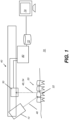
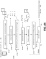
- FIG. 1 shows an imaging apparatus 70 for combined volume and color imaging of the teeth.
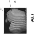
- a camera 40 projects structured imaging patterns 46 onto surface 20 of teeth 22 to obtain a contour image 48 according to an exemplary embodiment of the application.
- a control logic processor 80 or other type of computer controls the operation of an illumination array 10 and acquires digital image data obtained from a monochrome imaging sensor array 30.
- illumination array 10 projects patterned light onto an area 54 of the tooth, typically including structured patterns with multiple lines of light (e.g., having a predetermined spacing between lines).
- Image data from surface 20 is obtained from the patterned light detected by imaging sensor array 30.
- Control logic processor 80 processes the received image data and stores the mapping in memory 72.
- the reconstructed 3-D surface image from memory 72 is then optionally displayed on a display 74.
- Memory 72 may also include a display buffer.
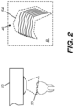
- FIG. 2 shows, in an inset labeled B, a portion of a typical fringe pattern 46 that is directed onto area 54 of surface 20 from illumination array 10.
- the structured pattern that is projected can be at the same power level at each shifted position. Alternately, different power levels can be used for projecting the structured pattern.
- camera 40 is used in still mode, held in the same fixed position for obtaining color component images as that used for structured light pattern projection and imaging.
- camera 40 can move while obtaining color component images and/or can move when used for structured light pattern projection and imaging.
- Illumination array 10 projects light of different color component wavelengths, typically Red (R), Green (G), and Blue (B), one at a time, and captures a separate image on monochrome sensor array 30 at each wavelength band. However, other color component combinations can be used.
- the captured images are also processed and stored by control logic processor 80 ( Fig. 1 ).
- FIG. 3 shows internal components of camera 40 for obtaining 3-D surface contour and color data according to an exemplary embodiment of the application.
- a fringe pattern generator 12 is energizable to form the structured light from illumination array 10 as a type of structured illumination or fringe pattern illumination, and to project the structured light thus formed as incident light toward tooth 22 through an optional polarizer 14 and through a projection lens 16.
- Light reflected and scattered from tooth 22 can be provided to sensor array 30 through imaging optics (e.g., an imaging lens 17 and an optional analyzer 28).
- Sensor array 30 is disposed along a detection path 88, at the image plane of imaging lens 17.
- a processor 34 in camera 40 accepts image content and other feedback information from sensor array 30 and, in response to this and other data, is actuable to effect the operation of pattern generator 12, as described in more detail subsequently.
- processor 34 for fringe projection imaging is to incrementally shift the position of the fringe and trigger the sensor array 30 to take images that are then used to calculate three-dimensional information of the tooth surface.
- processor 34 can be a computer, microprocessor, or other dedicated logic processing apparatus that executes programmed instructions and is in communication with control logic processor 80 that provides imaging system functions as described previously with respect to Fig. 1 .
- Intra-oral camera 40 of Fig. 3 optionally uses polarized light for surface contour imaging of tooth 22.
- Polarizer 14 provides the fringe pattern illumination from fringe pattern generator 12 as linearly polarized light.
- the transmission axis of analyzer 28 is parallel to the transmission axis of polarizer 14. With this arrangement, only light with the same polarization as the fringe pattern is provided to the sensor array 30.
- analyzer 28, in the path of reflected light to sensor array 30, can be rotated by an actuator 18 into either an orientation that matches the polarization transmission axis of polarizer 14 and obtains specular light from surface portions of the tooth or an orientation orthogonal to the polarization transmission axis of polarizer 14 for reduced specular content, obtaining more of the scattered light from inner portions of the tooth.
- actuator 18 in the path of reflected light to sensor array 30, can be rotated by an actuator 18 into either an orientation that matches the polarization transmission axis of polarizer 14 and obtains specular light from surface portions of the tooth or an orientation orthogonal to the polarization transmission axis of polarizer 14 for reduced specular content, obtaining more of the scattered light from inner portions of the tooth.
- combinations of polarized and non-polarized light can be used.
- a red light source 32r for providing color light for capturing three grayscale images, also called monochromatic shading images needed for construction of a full color image.
- Each of these light sources can include a single light emitting element, such as a light-emitting diode (LED) or of multiple light emitting elements.
- LED light-emitting diode
- the illumination path for structured pattern light from the fringe generator and the RGB light is the same; the detection path of light toward sensor array 30 is also the same for both structured pattern and RGB image content.
- Camera 40 has a focal point or focal plane F.
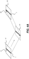
- the schematic diagram of Fig. 4A shows, with the example of a single line of light L, how patterned light from pattern generator 12 is used for obtaining surface contour information.
- a mapping is obtained as illumination array 10 directs a pattern of light onto surface 20 and a corresponding image of a line L' is formed on an imaging sensor array 30.
- Each pixel 38 of the projected pattern on imaging sensor array 30 maps to a corresponding pixel 13 on illumination array 10 according to modulation by surface 20. Shifts in pixel position, as represented in Fig. 4A , yield useful information about the contour of surface 20.
- the basic pattern shown in Fig. 4A can be implemented in a number of ways, using a variety of illumination sources and sequences and using one or more different types of sensor arrays 30.
- the plan view of Fig. 4B shows one structured light pattern 56 having multiple lines of light 84 spaced apart from each other.
- pattern 56 is directed to the tooth surface in a sequence or series of projected images in which lines 84 are incrementally shifted to the right or, alternately, to the left, in successive images of the projected series.
- Illumination array 10 can utilize any of a number of types of arrays used for light modulation and light patterning, such as a liquid crystal array or digital micromirror array, such as that provided using the Digital Light Processor or DLP device from Texas Instruments, Dallas, TX. This type of spatial light modulator is used in the illumination path to change the light pattern as needed for the mapping sequence.
- a liquid crystal array or digital micromirror array such as that provided using the Digital Light Processor or DLP device from Texas Instruments, Dallas, TX. This type of spatial light modulator is used in the illumination path to change the light pattern as needed for the mapping sequence.
- FIG. 5 shows a typical contour image 48 with projected pattern 46 on a tooth surface 20.
- contour lines can be indistinct on various parts of the surface.
- fringe pattern generator 12 Fig. 3
- fringe pattern generator 12 typically provides a sequence of patterned images, with the light and dark lines shifted to different positions as described with reference to Fig. 4B and, alternately, having different line thicknesses or distances between lines of light.
- Various sequences and patterns can be used. It should be noted that a number of variations are possible for providing an ordered set of structured light patterns within the scope of the present disclosure. According to exemplary embodiments, the number of structured patterned images in the ordered set that is projected exceeds 20 images, however, sequences that use more than 20 images or fewer than 20 images could also be used.
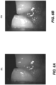
- Figs. 6A, 6B , and 6C show component grayscale or monochrome images 90r, 90g, and 90b of teeth obtained on monochrome sensor array 30 using red, green, and blue light from light sources 32r, 32g, and 32b ( Fig. 3 ) respectively.
- a grayscale representation of a color image can be formed by combining calibrated image data content for the red, green, and blue illumination.
- Color calibration data such as using a linear calibration matrix or other calibration mechanism, can be of particular value where a monochrome sensor is used to obtain color data and helps to compensate for inherent response characteristics of the sensor array for different wavelengths.
- Apparatus and/or method embodiments herein can capture shading images and/or perform texture mapping for 3-D modeling of teeth.
- Exemplary apparatus embodiments can use only monochrome sensors and one or more illumination sources to compose the color shading images, combined from monochrome shading images.
- a feature-point matching can register selected/all shading images and employ a texture mapping method to make displayed 3-D teeth model vivid to the observer and/or useful for assisting the diagnosis and treatment process.
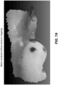
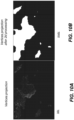
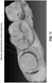
- Fig. 7A An example of the results of existing 3-D dental scanners is shown in Fig. 7A .
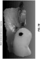
- Fig. 7B an example of texture mapping results on teeth according to exemplary method and/or apparatus embodiments of the application is shown in Fig. 7B .
- exemplary texture mapping methods and/or apparatus of the application provide a more accurate and/or more realistic representation of the surface appearance for tooth structures than do vertex mapping techniques.
- a number of views of teeth and surrounding structures can be captured. These can include a group of structured-light patterns for each view, projected onto tooth surfaces in sequence, with a corresponding set of fringe images acquired. Based on correspondence between projected patterns and captured fringe images, triangulation is performed to generate a 3-D point cloud of the teeth, using techniques familiar to those skilled in the art of contour imaging. For each view, LED or other light sources having specified wavelength or color spectrum bands are used to illuminate the teeth through an optical path in an ordered sequence. In addition, a set of monochromatic component shading images are captured by a monochrome sensor in sequence. 2-D feature points are extracted from the monochrome images.
- Transformations between the shading images are calculated, by which the monochromatic component shading images are registered to each other, such as using the extracted feature points.
- the color value for each pixel is recovered from the combined, registered pixel values taken from the shading images.
- a color shading image is also generated.
- 3-D point clouds generated in all views can be combined to generate the final 3-D mesh surfaces for the subject teeth.
- This final 3-D mesh defines a number of faces, each face defined by its nearest 3-D vertices, so that each face is planar and has a triangular construction, although more generally, each face is planar and has a polygonal shape formed from three or more sides.
- a point cloud of a surface can be used to define a triangular mesh and, optionally, a mesh having other polygonal shapes.
- the triangular mesh is the most geometrically primitive mesh and generally allows the most straightforward computation of polygonal shapes.
- the multiple combined faces extend across the surface of teeth and related structures and thus, plane section by plane section, define the surface contour.
- the visibility of each face in the mesh is determined and matched to the particular view that provides best observation on the faces in all views.
- the full set of views matched by all faces in the mesh serves as the key view frame.
- key relates to the use of a particular image view as a type of "color key", a resource used for color mapping, as the term is used by those skilled in the color imaging arts.
- a key view is a stored image taken at a particular aspect and used for texture mapping, as described in more detail subsequently.
- faces from the 3-D mesh are separated into groups called "texture fragments", wherein the faces in a particular texture fragment all geometrically connect to other faces in the same fragment and are assigned to the same key view.
- post-processing methods can be used to enhance the smoothness of boundaries between each texture fragment. This processing can be performed fragment by fragment, one at a time. In processing each fragment, the vertices that define the fragment are projected onto its view (e.g., its key view) using a standard projection routine, employing techniques well known for mapping 3-D points to a 2-D plane. This projection can also use the camera's intrinsic parameters extracted as part of camera calibration.
- the projected image coordinates of vertices are used as their texture coordinates.
- all boundaries between texture fragments are also projected onto views in the key view.
- a color blending method can be performed on the projected boundary in order to reduce color discrepancies and/or to correct for any color discrepancy between views due to the mapping.
- regions in color shading images corresponding to the projected texture fragments for each of the views can be extracted and packed into a single texture image, termed a "global texture map".
- a packing strategy can be used to make the packed texture image more compact and/or more efficient.
- the texture coordinates of all vertices can also be adjusted so that they align to the origin of the global texture map.
- all vertices with 3-D coordinates and 2-D texture coordinates and the global texture map can be output to a 3-D rendering engine for display, using techniques familiar to those skilled in volume image representation. Results can also be stored in memory or transmitted between processors.
- This first part of this procedure acquires the component monochrome images (e.g., using camera 40 ( Fig. 1 )) and can combine them to generate the composite color shading images for a particular view of the teeth.
- the component monochrome images e.g., using camera 40 ( Fig. 1 )
- Fig. 8A is a logic flow diagram that shows exemplary processing for forming composite color shading images ⁇ Is1 , Is2 , ... Isk ⁇ . This processing can be executed for each of the K views of the tooth obtained from reflectance imaging that obtains both contour images and color image content.
- One exemplary method then executes a sequence that generates a set of K corresponding component color shading images: Is 1 , Is 2 , ... Isk .
- Sub-steps of Part 1, executed for each view can be as follows:
- a decision step S170 can determine whether or not each view has been processed using the composite color shading image set generation step S100 procedures. Processing repeats for each view.
- Combining a set of the at least three monochromatic shading images can generate a composite 2-D color shading image, wherein each 2-D color shading image has color texture information or image structure information including color and additional appearance attributes, and an associated view pose.
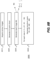
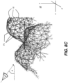
- Fig. 8B is a logic flow diagram that shows exemplary processing for generating and using mesh information in a mesh generation step S200.
- Fig. 8C shows a mesh M with individual planar faces Fc. Each face Fc is triangular in the example shown. Fig. 8C also shows the pose relative to mesh M.
- Each triangular (planar) face Fc in the mesh is defined using three vertices Vt.
- each of faces Fc and vertices Vt can be transformed into the coordinate system of each view V.
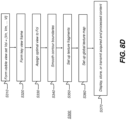
- Fig. 8D is a logic flow diagram that shows subsequent processing in an exemplary global texture map generation step S300, with exemplary procedures for forming a key view frame (Part 3), view assignment of faces (Part 4), generating a global texture map, contour smoothing (Part 5), and texture fragments setup (Part 6).
- the key view frame can be identified, using the following exemplary sequence, shown as form visible view step S310 and key frame setup step S320 in the logic flow diagram of Fig. 8D :
- Part 4 describes portions of exemplary view assignment step S330 of the Fig. 8D procedure.
- Fig. 9 shows an example of desired/selected view assignment of faces obtained from this Part.
- results of view assignment appear as shown in the example of Fig 9 .
- meshes in the same color or shade, grayscale, texture, marking or pattern, etc. represent the faces assigned to same view.
- This next sequence of steps performs contour and boundary smoothing in an exemplary contour smoothing step S340 ( Fig. 8D ) for the view assignment of faces.
- the next part of this procedure sets up texture fragments that group a set of faces to the same key view as part of an exemplary texture fragments setup step S350 in Fig. 8D .
- processing extracts the boundary faces of all texture fragments using the following exemplary strategy:
- Part 9 Exemplary extraction and packing of texture fragment regions in blended color shading images of key views.
- the procedure given here can complete an exemplary global texture map setup step S360 in the Fig. 8D process.
- a dual-lists strategy can be used to pack all texture fragments:
- the global texture map can be used to help speed image generation and provide texture content for a given view of a tooth and related structures.
- a global texture map is specified according to the desired view for display of the tooth image in step S370 ( Fig. 8D ). Then, to populate each visible face in the view with texture content, the global texture map provides a quick reference to the appropriate key view for the appearance of that face.
- the global texture map can be considered a scaled or reduced size representation that shows portions of the 2-D texture shading images as correlated to the texture fragments.
- the texture map is used for rendering the color texture 3-D surface contour image of the teeth.
- the global texture map can effectively provide a type of two-dimensional look--up table for visible faces in a given view. Providing a quick reference to image content in this way allows re-creation of a particular view to proceed quickly, without the need for considerable re-computation when changing the view angle or perspective, as with other related art texture-mapping schemes. Thus, in certain exemplary embodiments, rotation or movement of the image can appear to be performed in real time, without requiring extensive computing resources.
- a computer executes a program with stored instructions that perform on image data accessed from an electronic memory.
- a computer program of an exemplary embodiment of the application can be utilized by a suitable, general-purpose computer system, such as a personal computer or workstation, as well as by a microprocessor or other dedicated processor or programmable logic device.
- a suitable, general-purpose computer system such as a personal computer or workstation
- a microprocessor or other dedicated processor or programmable logic device such as a microprocessor or other dedicated processor or programmable logic device.
- many other types of computer systems can be used to execute the computer program of the application, including networked processors.
- the computer program for performing the method of the application may be stored in a computer readable storage medium.
- This medium may comprise, for example; magnetic storage media such as a magnetic disk (such as a hard drive) or magnetic tape or other portable type of magnetic disk; optical storage media such as an optical disc, optical tape, or machine readable bar code; solid state electronic storage devices such as random access memory (RAM), or read only memory (ROM); or any other physical device or medium employed to store a computer program.
- the computer program for performing exemplary method embodiments of the application may also be stored on computer readable storage medium that is connected to the image processor by way of the internet or other communication medium.
- Those skilled in the art will readily recognize that the equivalent of such a computer program product may also be constructed in hardware.
- the computer program product of the application may make use of various image manipulation algorithms and processes that are well known. It will be further understood that exemplary computer program product embodiments of the application may embody algorithms and processes not specifically shown or described herein that are useful for implementation. Such algorithms and processes may include conventional utilities that are within the ordinary skill of the image processing arts. Additional aspects of such algorithms and systems, and hardware and/or software for producing and otherwise processing the images or co-operating with computer program products of the application, are not specifically shown or described herein and may be selected from such algorithms, systems, hardware, components and elements known in the art.
- the act of "recording" images means storing image data in some type of memory circuit in order to use this image data for subsequent processing.
- the recorded image data itself may be stored more permanently or discarded once it is no longer needed for further processing.
- memory can refer to any type of temporary or more enduring data storage workspace used for storing and operating upon image data and accessible to a computer system.
- the memory could be non-volatile, using, for example, a long-term storage medium such as magnetic or optical storage. Alternately, the memory could be of a more volatile nature, using an electronic circuit, such as random-access memory (RAM) that is used as a temporary buffer or workspace by a microprocessor or other control logic processor device.
- Display data for example, is typically stored in a temporary storage buffer that is directly associated with a display device and is periodically refreshed as needed in order to provide displayed data.
- This temporary storage buffer can also be considered to be a memory, as the term is used in the present disclosure.
- Memory is also used as the data workspace for executing and storing intermediate and final results of calculations and other processing.
- Computer-accessible memory can be volatile, non-volatile, or a hybrid combination of volatile and non-volatile types. Computer-accessible memory of various types is provided on different components throughout the system for storing, processing, transferring, and displaying data, and for other functions.
- Method and/or apparatus embodiments according to the application can provide full color texture mapping in an intra-oral 3-D scanner with a monochrome sensor.
- the 3-D mesh can be generated from any conventional 3-D scanning methods (e.g., confocal imaging methods or multi-view or stereoscopic imaging methods).
- Exemplary embodiments according to the application can include various features described herein (individually or in combination).
- a method for forming a color texture mapping to a 3-D contour image of one or more teeth from image data recorded using an intra-oral camera with a monochrome sensor array can include obtaining a 3-D mesh representing a 3-D surface contour image of the one or more teeth according to recorded image data; generating a plurality of sets of at least three monochromatic shading images by projecting light of at least three different spectral bands onto the one or more teeth and recording at least three conesponding color component image data on the monochrome sensor array; combining selected sets of the at least three monochromatic shading images to generate a plurality of corresponding 2-D color texture shading images, where each of the plurality of color texture shading images has a view to the one or more teeth; assigning each 3-D mesh polygonal surface in the 3-D mesh representing the 3-D surface contour image of the one or more teeth to one of a subset of the 2-D color texture shading images; grouping 3-D mesh polygonal surfaces assigned to the same 2-D color texture shading image into a 3-D mesh fragment surface
- assigning each 3-D mesh polygonal surface forming the 3-D surface contour image of the one or more teeth to said one 2-D color texture shading images can include identifying 3-D mesh polygonal (e.g. triangular) surfaces forming the 3-D surface contour image of the one or more teeth; matching a first subset of 2-D color texture shading images by orientation alignment to a single one of the 3-D mesh polygonal surfaces; and determining 3-D mesh fragment surfaces by grouping remaining ones of the 3-D mesh polygonal surfaces to a single one of the matched 3-D mesh polygonal surfaces.
- determining representative coordinates for each of the 3-D mesh fragment surfaces can include projection of the 3-D mesh fragment surface coordinates into the assigned 2-D color texture shading image.
Landscapes
- Physics & Mathematics (AREA)
- Engineering & Computer Science (AREA)
- Health & Medical Sciences (AREA)
- Life Sciences & Earth Sciences (AREA)
- General Physics & Mathematics (AREA)
- Spectroscopy & Molecular Physics (AREA)
- Theoretical Computer Science (AREA)
- Computer Graphics (AREA)
- Animal Behavior & Ethology (AREA)
- Heart & Thoracic Surgery (AREA)
- Medical Informatics (AREA)
- Molecular Biology (AREA)
- Surgery (AREA)
- General Health & Medical Sciences (AREA)
- Public Health (AREA)
- Veterinary Medicine (AREA)
- Biophysics (AREA)
- Pathology (AREA)
- Biomedical Technology (AREA)
- Dentistry (AREA)
- Oral & Maxillofacial Surgery (AREA)
- Audiology, Speech & Language Pathology (AREA)
- Geometry (AREA)
- Software Systems (AREA)
- Dental Tools And Instruments Or Auxiliary Dental Instruments (AREA)
- Image Analysis (AREA)
- Endoscopes (AREA)
- Image Processing (AREA)
- Studio Devices (AREA)
- Image Generation (AREA)
- Color Television Image Signal Generators (AREA)
Applications Claiming Priority (2)
| Application Number | Priority Date | Filing Date | Title |
|---|---|---|---|
| US201562130110P | 2015-03-09 | 2015-03-09 | |
| PCT/US2015/049627 WO2016144382A1 (en) | 2015-03-09 | 2015-09-11 | Apparatus and method of texture mapping for dental 3d scanner |
Publications (3)
| Publication Number | Publication Date |
|---|---|
| EP3268935A1 EP3268935A1 (en) | 2018-01-17 |
| EP3268935B1 true EP3268935B1 (en) | 2024-11-06 |
| EP3268935C0 EP3268935C0 (en) | 2024-11-06 |
Family
ID=54207756
Family Applications (1)
| Application Number | Title | Priority Date | Filing Date |
|---|---|---|---|
| EP15771352.0A Active EP3268935B1 (en) | 2015-03-09 | 2015-09-11 | Apparatus and method of texture mapping for dental 3d scanner |
Country Status (8)
| Country | Link |
|---|---|
| US (1) | US10347031B2 (enExample) |
| EP (1) | EP3268935B1 (enExample) |
| JP (1) | JP2018514237A (enExample) |
| KR (1) | KR102508717B1 (enExample) |
| CN (1) | CN107257992B (enExample) |
| ES (1) | ES2996508T3 (enExample) |
| PL (1) | PL3268935T3 (enExample) |
| WO (1) | WO2016144382A1 (enExample) |
Families Citing this family (45)
| Publication number | Priority date | Publication date | Assignee | Title |
|---|---|---|---|---|
| US10192347B2 (en) * | 2016-05-17 | 2019-01-29 | Vangogh Imaging, Inc. | 3D photogrammetry |
| US10380762B2 (en) | 2016-10-07 | 2019-08-13 | Vangogh Imaging, Inc. | Real-time remote collaboration and virtual presence using simultaneous localization and mapping to construct a 3D model and update a scene based on sparse data |
| US10828130B2 (en) * | 2017-03-20 | 2020-11-10 | Align Technology, Inc. | Automated 2D/3D integration and lip spline autoplacement |
| EP3378379A1 (en) * | 2017-03-21 | 2018-09-26 | a.tron3d GmbH | Method for capturing the three-dimensional surface geometry of an object |
| WO2019032923A2 (en) * | 2017-08-10 | 2019-02-14 | D4D Technologies, Llc | INTRAORAL SCANNING DEVICE |
| US20200197136A1 (en) * | 2017-08-17 | 2020-06-25 | Trophy | Stencil for intraoral surface scanning |
| US10728445B2 (en) * | 2017-10-05 | 2020-07-28 | Hand Held Products Inc. | Methods for constructing a color composite image |
| CN108261171B (zh) * | 2017-10-30 | 2019-09-20 | 先临三维科技股份有限公司 | 口内三维扫描装置和方法 |
| US10839585B2 (en) | 2018-01-05 | 2020-11-17 | Vangogh Imaging, Inc. | 4D hologram: real-time remote avatar creation and animation control |
| WO2019155401A1 (en) * | 2018-02-12 | 2019-08-15 | 3M Innovative Properties Company | Projected texture pattern for intra-oral 3d imaging |
| CN108478188B (zh) * | 2018-02-12 | 2021-08-20 | 苏州佳世达电通有限公司 | 以结构光进行扫描的立体物件扫描装置 |
| US10803675B2 (en) * | 2018-02-20 | 2020-10-13 | Ivoclar Vivadent Ag | Dental model attributes transfer |
| US11083552B2 (en) * | 2018-02-20 | 2021-08-10 | Ivoclar Vivadent Ag | Rendering of dental models |
| EP3629337A1 (en) * | 2018-09-28 | 2020-04-01 | Ivoclar Vivadent AG | Rendering of dental models |
| US11080540B2 (en) | 2018-03-20 | 2021-08-03 | Vangogh Imaging, Inc. | 3D vision processing using an IP block |
| US10810783B2 (en) | 2018-04-03 | 2020-10-20 | Vangogh Imaging, Inc. | Dynamic real-time texture alignment for 3D models |
| CN108629826A (zh) * | 2018-05-15 | 2018-10-09 | 天津流形科技有限责任公司 | 一种纹理映射方法、装置、计算机设备及介质 |
| JP7312770B2 (ja) * | 2018-05-18 | 2023-07-21 | ケアストリーム デンタル エルエルシー | 角度ベースシェードマッチングを有する歯の3dスキャナ |
| US11170224B2 (en) | 2018-05-25 | 2021-11-09 | Vangogh Imaging, Inc. | Keyframe-based object scanning and tracking |
| US10753734B2 (en) | 2018-06-08 | 2020-08-25 | Dentsply Sirona Inc. | Device, method and system for generating dynamic projection patterns in a confocal camera |
| US11553988B2 (en) | 2018-06-29 | 2023-01-17 | Align Technology, Inc. | Photo of a patient with new simulated smile in an orthodontic treatment review software |
| WO2020037582A1 (en) * | 2018-08-23 | 2020-02-27 | Carestream Dental Technology Shanghai Co., Ltd. | Graph-based key frame selection for 3-d scanning |
| KR20200084698A (ko) * | 2019-01-03 | 2020-07-13 | 삼성전자주식회사 | 3차원 데이터를 압축하는 방법 및 장치 및 3차원 데이터를 재구성하는 방법 및 장치 |
| JP7473558B2 (ja) * | 2019-02-05 | 2024-04-23 | アルテック・ヨーロッパ・ソシエテ・ア・レスポンサビリテ・リミテ | 可動スキャナを使用したテクスチャモデルの生成 |
| EP3954297A4 (en) | 2019-04-11 | 2023-04-12 | DIO Corporation | METHOD AND DEVICE FOR DETECTING DENTAL OBJECTS AND METHOD AND DEVICE FOR IMAGE COMPLIANCE WITH A DENTAL OBJECT |
| KR102284623B1 (ko) * | 2019-04-11 | 2021-08-02 | 주식회사 디오 | 오랄 스캔 영상에서의 치아 오브젝트 검출 방법 및 장치 |
| US11232633B2 (en) | 2019-05-06 | 2022-01-25 | Vangogh Imaging, Inc. | 3D object capture and object reconstruction using edge cloud computing resources |
| US11170552B2 (en) | 2019-05-06 | 2021-11-09 | Vangogh Imaging, Inc. | Remote visualization of three-dimensional (3D) animation with synchronized voice in real-time |
| US11563929B2 (en) * | 2019-06-24 | 2023-01-24 | Align Technology, Inc. | Intraoral 3D scanner employing multiple miniature cameras and multiple miniature pattern projectors |
| US11335063B2 (en) | 2020-01-03 | 2022-05-17 | Vangogh Imaging, Inc. | Multiple maps for 3D object scanning and reconstruction |
| CN111189417B (zh) * | 2020-01-15 | 2020-11-27 | 浙江大学 | 基于高频图案干涉的二进制光栅图像投影反光抑制方法 |
| US12496721B2 (en) | 2020-05-08 | 2025-12-16 | Samsung Electronics Co., Ltd. | Virtual presence for telerobotics in a dynamic scene |
| JP7743440B2 (ja) * | 2020-05-26 | 2025-09-24 | デンツプライ・シロナ・インコーポレイテッド | マルチモーダル軟組織診断法のための方法及び装置 |
| KR102352985B1 (ko) * | 2020-07-07 | 2022-01-20 | 한국과학기술원 | 터치 스크린 기반의 가상 위젯을 통한 볼륨 데이터 시각화 인터페이스 방법 및 장치 |
| DE112021004183T5 (de) | 2020-08-05 | 2023-06-29 | Gyrus Acmi, Inc. D/B/A Olympus Surgical Technologies America | Tiefen- und konturerfassung für anatomische ziele |
| US11741748B2 (en) * | 2020-10-14 | 2023-08-29 | Shenzhen GOODIX Technology Co., Ltd. | Passive image depth sensing for object verification based on chromatic differentiation |
| CN113223176B (zh) * | 2021-05-12 | 2022-09-20 | 武汉中仪物联技术股份有限公司 | 多维度管道特征参数的获取方法和装置 |
| US11191620B1 (en) * | 2021-06-03 | 2021-12-07 | Oxilio Ltd | Systems and methods for generating an augmented 3D digital model of an anatomical structure of a subject |
| BR112023027068A2 (pt) * | 2021-06-22 | 2024-03-12 | Straumann Inst Ag | Construção de modelos 3d texturados de estruturas dentárias |
| JP7783728B2 (ja) * | 2021-12-02 | 2025-12-10 | 株式会社モリタ製作所 | データ処理装置、データ処理方法、データ処理プログラム、およびデータ処理システム |
| EP4202823A1 (en) * | 2021-12-21 | 2023-06-28 | Koninklijke Philips N.V. | System and method for digital reconstruction structures of an object |
| KR102461343B1 (ko) * | 2022-02-24 | 2022-10-31 | 서울대학교산학협력단 | 금속 인공 음영이 포함된 의료영상에서 치아 랜드마크 자동 검출 방법 및 시스템 |
| US12293461B2 (en) * | 2023-02-01 | 2025-05-06 | Streem, Llc | Edge enhancement with texture optimization |
| KR20250032682A (ko) * | 2023-08-31 | 2025-03-07 | 아크리얼 주식회사 | 구강 스캐너를 위한 시각적 가이드 제공 방법 및 시스템 |
| CN120014171B (zh) * | 2025-01-24 | 2025-08-19 | 中科博特智能科技(安徽)有限公司 | 基于云台扫描识别的模型构造方法及装置 |
Family Cites Families (11)
| Publication number | Priority date | Publication date | Assignee | Title |
|---|---|---|---|---|
| DE19524855A1 (de) | 1995-07-07 | 1997-01-09 | Siemens Ag | Verfahren und Vorrichtung zur rechnergestützten Restauration von Zähnen |
| US7698068B2 (en) * | 2004-06-17 | 2010-04-13 | Cadent Ltd. | Method for providing data associated with the intraoral cavity |
| JP4464773B2 (ja) * | 2004-09-03 | 2010-05-19 | 日本放送協会 | 3次元モデル表示装置及び3次元モデル表示プログラム |
| JP4282587B2 (ja) * | 2004-11-16 | 2009-06-24 | 株式会社東芝 | テクスチャ・マッピング装置 |
| JP2007102734A (ja) * | 2005-10-07 | 2007-04-19 | Konami Digital Entertainment:Kk | 画像処理装置、画像処理方法及びプログラム |
| KR101844549B1 (ko) * | 2010-07-12 | 2018-04-02 | 쓰리세이프 에이/에스 | 질감 특징을 이용한 객체의 3d 모형제작 |
| US8208704B2 (en) * | 2010-07-13 | 2012-06-26 | Carestream Health, Inc. | Dental shade mapping |
| US9349182B2 (en) * | 2011-11-10 | 2016-05-24 | Carestream Health, Inc. | 3D intraoral measurements using optical multiline method |
| US20140253686A1 (en) | 2013-03-08 | 2014-09-11 | Victor C. Wong | Color 3-d image capture with monochrome image sensor |
| US9675428B2 (en) * | 2013-07-12 | 2017-06-13 | Carestream Health, Inc. | Video-based auto-capture for dental surface imaging apparatus |
| US9224238B2 (en) * | 2013-12-06 | 2015-12-29 | Google Inc. | Seamless texturing of 3D meshes of objects from multiple views |
-
2015
- 2015-09-11 WO PCT/US2015/049627 patent/WO2016144382A1/en not_active Ceased
- 2015-09-11 US US15/546,396 patent/US10347031B2/en active Active
- 2015-09-11 PL PL15771352.0T patent/PL3268935T3/pl unknown
- 2015-09-11 CN CN201580074592.4A patent/CN107257992B/zh active Active
- 2015-09-11 JP JP2017539009A patent/JP2018514237A/ja not_active Ceased
- 2015-09-11 KR KR1020177020071A patent/KR102508717B1/ko active Active
- 2015-09-11 ES ES15771352T patent/ES2996508T3/es active Active
- 2015-09-11 EP EP15771352.0A patent/EP3268935B1/en active Active
Also Published As
| Publication number | Publication date |
|---|---|
| KR102508717B1 (ko) | 2023-03-09 |
| EP3268935A1 (en) | 2018-01-17 |
| WO2016144382A1 (en) | 2016-09-15 |
| KR20170126860A (ko) | 2017-11-20 |
| US20180025529A1 (en) | 2018-01-25 |
| CN107257992B (zh) | 2021-02-02 |
| PL3268935T3 (pl) | 2025-02-10 |
| CN107257992A (zh) | 2017-10-17 |
| JP2018514237A (ja) | 2018-06-07 |
| US10347031B2 (en) | 2019-07-09 |
| ES2996508T3 (en) | 2025-02-12 |
| EP3268935C0 (en) | 2024-11-06 |
Similar Documents
| Publication | Publication Date | Title |
|---|---|---|
| EP3268935B1 (en) | Apparatus and method of texture mapping for dental 3d scanner | |
| EP3022525B1 (en) | Method of capturing three-dimensional (3d) information on a structure | |
| US20140253686A1 (en) | Color 3-d image capture with monochrome image sensor | |
| US9314150B2 (en) | System and method for detecting tooth cracks via surface contour imaging | |
| EP3401876B2 (en) | Detection of a movable object when 3d scanning a rigid object | |
| US8144954B2 (en) | Lighting compensated dynamic texture mapping of 3-D models | |
| JP5633058B1 (ja) | 3次元計測装置及び3次元計測方法 | |
| EP3382645B1 (en) | Method for generation of a 3d model based on structure from motion and photometric stereo of 2d sparse images | |
| US20110292179A1 (en) | Imaging system and method | |
| JP2003203220A (ja) | 三次元画像処理方法、三次元画像処理装置、三次元画像処理システムおよび三次元画像処理プログラム | |
| US20170103569A1 (en) | Operator interface for 3d surface display using 2d index image | |
| JP6580761B1 (ja) | 偏光ステレオカメラによる深度取得装置及びその方法 | |
| Brostow et al. | Video normals from colored lights | |
| EP3195253B1 (en) | 3- d intraoral measurements using optical multiline method | |
| Smithwick et al. | Depth enhancement using a scanning fiber optical endoscope | |
| US11302073B2 (en) | Method for texturing a 3D model | |
| WO2020037582A1 (en) | Graph-based key frame selection for 3-d scanning | |
| Lacher | 3D breast surface reconstructions from consumer-grade RGB-D cameras | |
| Visentini-Scarzanella et al. | Tissue shape acquisition with a hybrid structured light and photometric stereo endoscopic system | |
| US20250241733A1 (en) | Timelapse visualization on colored 3d models | |
| Killpack | Visualization of three-dimensional models from multiple texel images created from fused ladar/digital imagery |
Legal Events
| Date | Code | Title | Description |
|---|---|---|---|
| STAA | Information on the status of an ep patent application or granted ep patent |
Free format text: STATUS: THE INTERNATIONAL PUBLICATION HAS BEEN MADE |
|
| PUAI | Public reference made under article 153(3) epc to a published international application that has entered the european phase |
Free format text: ORIGINAL CODE: 0009012 |
|
| STAA | Information on the status of an ep patent application or granted ep patent |
Free format text: STATUS: REQUEST FOR EXAMINATION WAS MADE |
|
| 17P | Request for examination filed |
Effective date: 20170717 |
|
| AK | Designated contracting states |
Kind code of ref document: A1 Designated state(s): AL AT BE BG CH CY CZ DE DK EE ES FI FR GB GR HR HU IE IS IT LI LT LU LV MC MK MT NL NO PL PT RO RS SE SI SK SM TR |
|
| AX | Request for extension of the european patent |
Extension state: BA ME |
|
| DAV | Request for validation of the european patent (deleted) | ||
| DAX | Request for extension of the european patent (deleted) | ||
| STAA | Information on the status of an ep patent application or granted ep patent |
Free format text: STATUS: EXAMINATION IS IN PROGRESS |
|
| 17Q | First examination report despatched |
Effective date: 20200224 |
|
| RAP1 | Party data changed (applicant data changed or rights of an application transferred) |
Owner name: CARESTREAM DENTAL LLC |
|
| RAP1 | Party data changed (applicant data changed or rights of an application transferred) |
Owner name: DENTAL IMAGING TECHNOLOGIES CORPORATION |
|
| REG | Reference to a national code |
Ref country code: DE Ref legal event code: R079 Free format text: PREVIOUS MAIN CLASS: G06T0015040000 Ipc: A61B0005000000 Ref country code: DE Ref legal event code: R079 Ref document number: 602015090327 Country of ref document: DE Free format text: PREVIOUS MAIN CLASS: G06T0015040000 Ipc: A61B0005000000 |
|
| GRAP | Despatch of communication of intention to grant a patent |
Free format text: ORIGINAL CODE: EPIDOSNIGR1 |
|
| STAA | Information on the status of an ep patent application or granted ep patent |
Free format text: STATUS: GRANT OF PATENT IS INTENDED |
|
| RIC1 | Information provided on ipc code assigned before grant |
Ipc: G06T 15/04 20110101ALI20240524BHEP Ipc: G01J 3/50 20060101ALI20240524BHEP Ipc: A61B 5/107 20060101ALI20240524BHEP Ipc: A61B 5/00 20060101AFI20240524BHEP |
|
| INTG | Intention to grant announced |
Effective date: 20240617 |
|
| GRAS | Grant fee paid |
Free format text: ORIGINAL CODE: EPIDOSNIGR3 |
|
| GRAA | (expected) grant |
Free format text: ORIGINAL CODE: 0009210 |
|
| STAA | Information on the status of an ep patent application or granted ep patent |
Free format text: STATUS: THE PATENT HAS BEEN GRANTED |
|
| AK | Designated contracting states |
Kind code of ref document: B1 Designated state(s): AL AT BE BG CH CY CZ DE DK EE ES FI FR GB GR HR HU IE IS IT LI LT LU LV MC MK MT NL NO PL PT RO RS SE SI SK SM TR |
|
| REG | Reference to a national code |
Ref country code: GB Ref legal event code: FG4D |
|
| REG | Reference to a national code |
Ref country code: CH Ref legal event code: EP |
|
| REG | Reference to a national code |
Ref country code: DE Ref legal event code: R096 Ref document number: 602015090327 Country of ref document: DE |
|
| REG | Reference to a national code |
Ref country code: IE Ref legal event code: FG4D |
|
| U01 | Request for unitary effect filed |
Effective date: 20241205 |
|
| U07 | Unitary effect registered |
Designated state(s): AT BE BG DE DK EE FI FR IT LT LU LV MT NL PT RO SE SI Effective date: 20241213 |
|
| REG | Reference to a national code |
Ref country code: ES Ref legal event code: FG2A Ref document number: 2996508 Country of ref document: ES Kind code of ref document: T3 Effective date: 20250212 |
|
| PG25 | Lapsed in a contracting state [announced via postgrant information from national office to epo] |
Ref country code: HR Free format text: LAPSE BECAUSE OF FAILURE TO SUBMIT A TRANSLATION OF THE DESCRIPTION OR TO PAY THE FEE WITHIN THE PRESCRIBED TIME-LIMIT Effective date: 20241106 Ref country code: IS Free format text: LAPSE BECAUSE OF FAILURE TO SUBMIT A TRANSLATION OF THE DESCRIPTION OR TO PAY THE FEE WITHIN THE PRESCRIBED TIME-LIMIT Effective date: 20250306 |
|
| PG25 | Lapsed in a contracting state [announced via postgrant information from national office to epo] |
Ref country code: NO Free format text: LAPSE BECAUSE OF FAILURE TO SUBMIT A TRANSLATION OF THE DESCRIPTION OR TO PAY THE FEE WITHIN THE PRESCRIBED TIME-LIMIT Effective date: 20250206 |
|
| PG25 | Lapsed in a contracting state [announced via postgrant information from national office to epo] |
Ref country code: GR Free format text: LAPSE BECAUSE OF FAILURE TO SUBMIT A TRANSLATION OF THE DESCRIPTION OR TO PAY THE FEE WITHIN THE PRESCRIBED TIME-LIMIT Effective date: 20250207 |
|
| PG25 | Lapsed in a contracting state [announced via postgrant information from national office to epo] |
Ref country code: RS Free format text: LAPSE BECAUSE OF FAILURE TO SUBMIT A TRANSLATION OF THE DESCRIPTION OR TO PAY THE FEE WITHIN THE PRESCRIBED TIME-LIMIT Effective date: 20250206 |
|
| PG25 | Lapsed in a contracting state [announced via postgrant information from national office to epo] |
Ref country code: SM Free format text: LAPSE BECAUSE OF FAILURE TO SUBMIT A TRANSLATION OF THE DESCRIPTION OR TO PAY THE FEE WITHIN THE PRESCRIBED TIME-LIMIT Effective date: 20241106 |
|
| PG25 | Lapsed in a contracting state [announced via postgrant information from national office to epo] |
Ref country code: SK Free format text: LAPSE BECAUSE OF FAILURE TO SUBMIT A TRANSLATION OF THE DESCRIPTION OR TO PAY THE FEE WITHIN THE PRESCRIBED TIME-LIMIT Effective date: 20241106 |
|
| PG25 | Lapsed in a contracting state [announced via postgrant information from national office to epo] |
Ref country code: CZ Free format text: LAPSE BECAUSE OF FAILURE TO SUBMIT A TRANSLATION OF THE DESCRIPTION OR TO PAY THE FEE WITHIN THE PRESCRIBED TIME-LIMIT Effective date: 20241106 |
|
| U20 | Renewal fee for the european patent with unitary effect paid |
Year of fee payment: 11 Effective date: 20250807 |
|
| PLBE | No opposition filed within time limit |
Free format text: ORIGINAL CODE: 0009261 |
|
| STAA | Information on the status of an ep patent application or granted ep patent |
Free format text: STATUS: NO OPPOSITION FILED WITHIN TIME LIMIT |
|
| REG | Reference to a national code |
Ref country code: CH Ref legal event code: U11 Free format text: ST27 STATUS EVENT CODE: U-0-0-U10-U11 (AS PROVIDED BY THE NATIONAL OFFICE) Effective date: 20251001 |
|
| 26N | No opposition filed |
Effective date: 20250807 |
|
| PGFP | Annual fee paid to national office [announced via postgrant information from national office to epo] |
Ref country code: TR Payment date: 20250905 Year of fee payment: 11 Ref country code: PL Payment date: 20250707 Year of fee payment: 11 |
|
| PGFP | Annual fee paid to national office [announced via postgrant information from national office to epo] |
Ref country code: GB Payment date: 20250703 Year of fee payment: 11 |
|
| PGFP | Annual fee paid to national office [announced via postgrant information from national office to epo] |
Ref country code: IE Payment date: 20250702 Year of fee payment: 11 |