EP3268109B1 - Separating device for separating particles - Google Patents
Separating device for separating particles Download PDFInfo
- Publication number
- EP3268109B1 EP3268109B1 EP16703133.5A EP16703133A EP3268109B1 EP 3268109 B1 EP3268109 B1 EP 3268109B1 EP 16703133 A EP16703133 A EP 16703133A EP 3268109 B1 EP3268109 B1 EP 3268109B1
- Authority
- EP
- European Patent Office
- Prior art keywords
- separating
- separation
- particles
- separator
- gas stream
- Prior art date
- Legal status (The legal status is an assumption and is not a legal conclusion. Google has not performed a legal analysis and makes no representation as to the accuracy of the status listed.)
- Active
Links
Images


Classifications
-
- B—PERFORMING OPERATIONS; TRANSPORTING
- B01—PHYSICAL OR CHEMICAL PROCESSES OR APPARATUS IN GENERAL
- B01D—SEPARATION
- B01D50/00—Combinations of methods or devices for separating particles from gases or vapours
- B01D50/20—Combinations of devices covered by groups B01D45/00 and B01D46/00
-
- B—PERFORMING OPERATIONS; TRANSPORTING
- B01—PHYSICAL OR CHEMICAL PROCESSES OR APPARATUS IN GENERAL
- B01D—SEPARATION
- B01D45/00—Separating dispersed particles from gases or vapours by gravity, inertia, or centrifugal forces
- B01D45/04—Separating dispersed particles from gases or vapours by gravity, inertia, or centrifugal forces by utilising inertia
- B01D45/08—Separating dispersed particles from gases or vapours by gravity, inertia, or centrifugal forces by utilising inertia by impingement against baffle separators
-
- B—PERFORMING OPERATIONS; TRANSPORTING
- B01—PHYSICAL OR CHEMICAL PROCESSES OR APPARATUS IN GENERAL
- B01D—SEPARATION
- B01D46/00—Filters or filtering processes specially modified for separating dispersed particles from gases or vapours
- B01D46/02—Particle separators, e.g. dust precipitators, having hollow filters made of flexible material
- B01D46/06—Particle separators, e.g. dust precipitators, having hollow filters made of flexible material with means keeping the working surfaces flat
- B01D46/08—Particle separators, e.g. dust precipitators, having hollow filters made of flexible material with means keeping the working surfaces flat the working surfaces forming a star shape
-
- B—PERFORMING OPERATIONS; TRANSPORTING
- B05—SPRAYING OR ATOMISING IN GENERAL; APPLYING FLUENT MATERIALS TO SURFACES, IN GENERAL
- B05B—SPRAYING APPARATUS; ATOMISING APPARATUS; NOZZLES
- B05B14/00—Arrangements for collecting, re-using or eliminating excess spraying material
- B05B14/40—Arrangements for collecting, re-using or eliminating excess spraying material for use in spray booths
- B05B14/43—Arrangements for collecting, re-using or eliminating excess spraying material for use in spray booths by filtering the air charged with excess material
-
- B—PERFORMING OPERATIONS; TRANSPORTING
- B05—SPRAYING OR ATOMISING IN GENERAL; APPLYING FLUENT MATERIALS TO SURFACES, IN GENERAL
- B05B—SPRAYING APPARATUS; ATOMISING APPARATUS; NOZZLES
- B05B16/00—Spray booths
- B05B16/60—Ventilation arrangements specially adapted therefor
-
- Y—GENERAL TAGGING OF NEW TECHNOLOGICAL DEVELOPMENTS; GENERAL TAGGING OF CROSS-SECTIONAL TECHNOLOGIES SPANNING OVER SEVERAL SECTIONS OF THE IPC; TECHNICAL SUBJECTS COVERED BY FORMER USPC CROSS-REFERENCE ART COLLECTIONS [XRACs] AND DIGESTS
- Y02—TECHNOLOGIES OR APPLICATIONS FOR MITIGATION OR ADAPTATION AGAINST CLIMATE CHANGE
- Y02P—CLIMATE CHANGE MITIGATION TECHNOLOGIES IN THE PRODUCTION OR PROCESSING OF GOODS
- Y02P70/00—Climate change mitigation technologies in the production process for final industrial or consumer products
- Y02P70/10—Greenhouse gas [GHG] capture, material saving, heat recovery or other energy efficient measures, e.g. motor control, characterised by manufacturing processes, e.g. for rolling metal or metal working
Definitions
- the present invention relates to a separation device for separating particles from a raw gas flow, a proportion of solid, liquid and / or pasty particles being carried along in the raw gas flow.
- the raw gas flow passes through the separation device in a main flow direction and has a main separator which separates at least some of the particles from the raw gas flow, the raw gas flow flowing through the main separator in the main flow direction and exiting the main separator as a clean gas flow.
- a separation device for separating particles is for example from the DE102007040901A1 known and has as the main separator a filter device for separating wet paint overspray from a raw gas stream containing overspray particles.
- the filter device comprises a filter element for separating the overspray from the raw gas flow. The raw gas flow flows through the filter element in a main flow direction and emerges from the filter device as a clean gas flow.
- a separation device for separating particles is also from the EP0875275A1 and from the WO2015 / 090942A1 known and has a multi-stage separation device with a pre-separator and a main separator, wherein the pre-separator comprises a plurality of rotatable separating elements with bristles, and wherein the bristles of adjacent separating elements are in contact.
- the present invention is based on the object of providing a separating device whose main separator has a long service life. Such a separation device should also be able to be operated inexpensively by regeneration during operation.
- a generic separation device for separating particles from a raw gas stream which one Pre-separator for separating at least a part of the particles from the raw gas flow, which is arranged upstream of the main separator in such a way that the raw gas flow in the main flow direction first flows through the pre-separator and then through the main separator.
- the pre-separator comprises a separator element which is provided for deflecting the raw gas flow, the separator element comprising a shaft and a radial surface element which is arranged on the shaft protruding radially from the shaft and which has a separation surface arranged on the radial surface element from which particles the raw gas stream can be deposited.
- the outer contour of a separating element is preferably the surface of a fictitious approximately cylindrical and / or prism-shaped body.
- a separating element is designed to be rotatable continuously or at intervals about an axis of rotation in order to adjust the separating element between several working positions.
- the separation element has at least two separation surfaces for separating particles, with one separation surface of the separation element being in a separation position in a first working position of the separation element, while at the same time another separation surface of the same separation element is in a regeneration position.
- a separation surface of the separation element acts as a flow guide element that protrudes into the flow path of the raw gas flow, with at least one separation surface each acting as a flow guide element of two adjacently arranged separation elements jointly causing a deflection of the raw gas flow from the main flow direction, whereby the particles contained in the raw gas flow due to inertia the separation surfaces are deposited, the separation surfaces of second adjacently arranged separation elements being arranged one behind the other in the main flow direction in such a way that they are swept over by the raw gas flow one after the other.
- the raw gas flow is a gas flow, in particular an air flow, which at least at times carries certain particles with it.
- the gas flow is loaded with such particles, for example in a work area, and flows off as a raw gas flow Working area to and through the separation device.
- the raw gas stream is discharged, cleaned and / or recycled in the separation device. Particles are removed from the raw gas flow.
- the raw gas stream After the raw gas stream has been discharged, cleaned and / or recycled, it first flows as a clean gas stream from the separation device into an optionally available conditioning device and then as a gas stream into the work area in order to pick up particles there again. Have a clean gas flow and / or a gas flow in particular a smaller number of particles than the raw gas stream. Optionally, after flowing through the separation device, the clean gas flow and / or the gas flow no longer contain any particles that have entered the raw gas flow in the working area.
- the particles contained in the raw gas stream comprise solid, gaseous, liquid and / or pasty material and / or a mixture of substances.
- Solid, liquid and / or pasty particles form an aerosol together with the gas flow.
- Particles are in particular paint overspray particles, preferably droplets, which get into the gas flow and / or the raw gas flow when a liquid is applied to a workpiece arranged in the work area.
- the particles are preferably carried along by the gas flow and / or the raw gas flow and are spatially displaced in the direction of flow. At least some of the particles are removed from the gas flow and / or the raw gas flow by means of the separation device.
- the separator has a pre-separator and a main separator and removes particles from the raw gas flow, in particular those particles which have been taken up in a working area by a gas flow, a clean gas flow and / or the raw gas flow.
- the separating device in addition to a pre-separator and a main separator, the separating device has a post-separator which can separate particles that have passed through the pre-separator and the main separator.
- a work area comprises, for example, a painting booth in which a workpiece is painted, and a gas flow flows through it.
- the raw gas stream After flowing through the separation device, the raw gas stream preferably contains a smaller number of particles than before entering the separation device.
- the raw gas stream no longer contains any particles, preferably no longer any particles that have entered the raw gas stream in the working area.
- a raw gas stream purified in this way is referred to as a clean gas stream and can in particular at least partially fed back to a work area, in particular the same or one or more other work areas, in order to pick up particles there.
- the main separator is preferably designed as a disposable system, a reusable system and / or a permanent filter.
- the main separator comprises, for example, a ceramic, a metallic and / or a polymer material with a lattice structure and / or with a porous consistency.
- the main separator separates particles contained in the raw gas flow at least partially, preferably completely, from the raw gas flow.
- a gas flow enters the main separator as a raw gas flow, passes it and exits the main separator as a raw gas flow and / or as a clean gas flow.
- a stream of clean gas is then fed back into the work area.
- the pre-separator is arranged upstream of the main separator and separates at least some of the particles contained in the raw gas flow from the raw gas flow.
- the proportion of particles in the raw gas flow when the raw gas flow enters the main separator is preferably lower than when using a separating device without a pre-separator. This reduces the load on the main separator.
- a direction in which the raw gas flow essentially passes through the separation device is defined as the main flow direction.
- the pre-separator and the main separator are preferably arranged in such a way that the raw gas stream first passes the pre-separator and then the main separator in the main flow direction.
- the pre-separator and the main separator are preferably arranged on an axis which is oriented essentially parallel to the main flow direction.
- a separation device can have one or more main flow directions which the raw gas stream follows at least temporarily.
- a Main flow direction of a pre-separator can be different from a main flow direction of a main separator.
- one or more secondary flow directions can be assigned to the separation device in addition to one or more main flow directions, which the raw gas flow follows at least in time and / or in sections when passing through the separation device.
- a mean direction of flow of the raw gas flow when passing the separation device essentially corresponds to the main direction of flow.
- the separation element is arranged in the flow path of the raw gas flow in such a way that the raw gas flow passing through the pre-separator is at least partially diverted from a main flow direction and, for example, at least temporarily follows a secondary flow direction that deviates from the main flow direction.
- the separation element comprises a shaft and a radial surface element and / or a surface element.
- a radial surface element is arranged on the shaft protruding radially from the shaft.
- a radial surface element is formed from a material which has a modulus of elasticity E that is between 0.5 kN / mm 2 and 1,000 kN / mm 2 , preferably between 5 and 250 kN / mm 2 .
- a radial surface element made of such a material can advantageously have a sufficiently high flexural strength so that it is not or only slightly bent by the raw gas flow impinging on the radial surface element.
- the separation surface is arranged on the separation element, in particular on a radial surface element and / or surface element of the separation element. Particles contained in the raw gas stream can interact with the separation surface at least temporarily. The interaction of the particles with the separation surface is optionally reversible or irreversible. It is possible to bind particles chemically and / or physically to the separation surface.
- Particles contained in the raw gas flow are removed from the raw gas flow when the raw gas flow is at least partially diverted from the main flow direction when passing through the pre-separator and at least temporarily follows a secondary flow direction. Due to inertia, the particles contained in the raw gas flow continue to follow the main flow direction, at least in part, hit the separation surface and are separated there.
- the pre-separator is preferably designed as an impact separator which has a separation surface on which certain particles impinge and which separates particles contained in the raw gas flow by means of inertia.
- the outer contour of a separating element is preferably the surface of a fictitious approximately cylindrical and / or prism-shaped body. It is considered whether the points of the separation element which are the furthest away from a central longitudinal axis of the separation element, therefore the outermost points of the separation element, lie on the surface of a circular cylinder or a polygonal prism.
- a separator element the outermost points of which are approximately on the surface of a circular cylinder, has approximately a (circular) cylindrical outer contour.
- a separation element the outermost points of which lie approximately on the surface of a polygonal prism, has approximately a prism-shaped outer contour.
- the distance between two separation surfaces of adjacent separation elements is preferably so great that a raw gas stream can flow through between the two separation surfaces.
- the distance between two separation surfaces of adjacent separation elements is preferably in an interval between 0.1 cm and 50 cm.
- the distance between two separation surfaces of adjacent separation elements is particularly preferably in an interval between 1 cm and 20 cm.
- the pre-separator comprises a separating element which has a passage opening for the passage of part of the raw gas flow.
- the raw gas flow can pass this passage opening, with at least some of the particles contained in the raw gas flow preferably being deposited on the separation element.
- a passage opening can, for example, comprise a bore in a separation element and is preferably arranged in a radial surface element and / or in a separation surface.
- a separation element can have a multiplicity of passage openings, in particular a multiplicity of bores, for the passage of part of the raw gas flow.
- a diameter of a passage opening is preferably selected such that it is smaller than a diameter of a particle, preferably smaller than an average diameter of several particles.
- a separation element optionally has a drive unit by means of which the separation element can be rotated about an axis of rotation.
- a drive unit can be in a force-locking connection with one or more separating elements.
- a separating element can have a braking device, by means of which a rotation of the separating element about an axis of rotation can optionally and / or at least temporarily be prevented. The raw gas flow passing through the separating element and impinging on it sets the separating element in a rotary motion by transferring kinetic energy contained in the raw gas flow to the separating element and converting it into a rotary motion around the axis of rotation.
- An axis of rotation of a separation element is preferably located within an outer contour of the separation element.
- an axis of rotation lies on a longitudinal axis, for example on a central longitudinal axis, of the shaft of the separation element.
- a longitudinal axis extends along a longitudinal direction of the shaft.
- the longitudinal direction of the shaft extends, for example, largely in the vertical direction.
- the longitudinal direction of the shaft extends largely in the horizontal direction.
- the outer edges of the separating element and / or an outer contour of the separating element sweep over a cylinder-shaped body of rotation.
- An axis of rotation of the separation element preferably lies on an axis of symmetry of the separation element.
- An axis of rotation particularly preferably intersects the center point of each of the two end faces of the rotary body and / or lies on a central longitudinal axis of the separation element.
- an axis of rotation intersects the central longitudinal axis of the separation element at a point within the outer contour of the separation element.
- a separating element can have a pivot axis about which the separating element can be pivoted.
- At least two radial surface elements and / or surface elements, each with at least one separation surface, on which particles can be separated from the raw gas flow, are provided on the separation element.
- a separation surface of a radial surface element and / or a surface element is preferably in a separation position, while a separation surface of another radial surface element and / or surface element is at the same time in a regeneration position.
- Each separation surface can optionally assume one of the positions.
- a first separation surface is preferably in a first auxiliary plane and a second separation surface is preferably in a second auxiliary plane.
- an axis of intersection of the two intersecting auxiliary planes lies on the axis of rotation of the separation element.
- cutting axes of such auxiliary planes can also lie next to an axis of rotation of a separation element.
- a separation surface is arranged in relation to the raw gas flow in such a way that a dynamic gas pressure at the separation surface is temporarily unequal to zero.
- Turbulent flow conditions are preferably present in the raw gas flow, at least one directional component of the raw gas flow being oriented towards the separation surface. The raw gas flow and / or the particles in the raw gas flow collide with the separation surface and the particles are separated on the separation surface when the separation surface is in the separation position.
- a separation surface arranged in the separation position is preferably located in a separation zone of the pre-separator.
- a separation surface is arranged in relation to the raw gas flow in such a way that the dynamic gas pressure on the separation surface is generally at least approximately equal to zero.
- a stationary gas layer is preferably formed on the separation surface. The raw gas flow and / or the particles in the raw gas flow optionally and / or temporarily do not collide with the separation surface and at least temporarily no particles are separated on the separation surface when the separation surface is in the regeneration position.
- a separation surface arranged in the regeneration position is preferably located in a regeneration zone of the pre-separator.
- Rotating the separating element about the axis of rotation effects an adjustment of the separating element between the working positions.
- a first separation surface of this separation element assumes a separation position and is arranged in a separation zone, while at the same time a second separation surface of the same separation element assumes a regeneration position and is arranged in a regeneration zone.
- the first separation surface of the separation element assumes a regeneration position, while at the same time the second separation surface of the same separation element assumes a separation position.
- Particles are preferably deposited on the one separation surface, while at the same time no particles are deposited on the other separation surface. With further preference, particles are deposited on the one separation surface, while the other separation surface is freed from separated particles.
- a separation surface can at least temporarily assume a transition position and / or a rest position in addition to a separation position and a regeneration position
- a third working position is optionally provided for the separation element.
- a separation surface can at least temporarily partially or completely from the flow path of the raw gas flow and / or from the Pre-separator must be removed.
- the separation surface is located outside the area through which the raw gas flow flows, with particles contained in the raw gas flow being separated on another separation surface or, alternatively, being able to pass through the pre-separator.
- a separation surface arranged in a transition and / or rest position is preferably located in a transition and / or rest zone.
- a specific separation surface assumes a different position in each working position of a separation element than in a different working position of the separation element.
- the separation surface is assigned at least in sections a coating made of an auxiliary material which interacts chemically and / or physically with certain particles.
- the auxiliary material has solid, liquid and / or pasty particles which are arranged as a coating on the separation surface and cover the separation surface at least in sections. Particles of the auxiliary material and / or auxiliary material particles preferably interact chemically and / or physically with the separation surface and / or with particles of the raw gas flow. The particles of the auxiliary material act as a separating layer between the separation surface and the particles of the raw gas flow. Contact between particles of the raw gas flow and the separation surface and / or direct contact of particles of the raw gas flow with the separation surface can thus be restricted or even prevented.
- a metallic, ceramic, inorganic and / or organic layer can also be provided as the coating.
- a metallic, ceramic, inorganic and / or organic layer can, for example, have been applied to the deposition surface via a physical and / or chemical deposition from a gas phase (physical vapor deposition or chemical vapor deposition).
- a layer can limit or even prevent contact between particles of the raw gas flow and the separation surface and / or direct contact of particles of the raw gas flow with the separation surface.
- the pre-separator optionally includes a regeneration device with an auxiliary material system.
- the auxiliary material system is used to apply auxiliary material to a separation surface.
- a coating of the separation surface is formed from an auxiliary material that comprises a ferromagnetic material, and the pre-separator has a magnetic coil and / or a permanent magnet for continuous or intermittent application of a magnetic field to the separation surface.
- a ferromagnetic material as a component of the auxiliary material includes, for example, a ferromagnetic powder such as iron powder, magnetite powder, cobalt powder and / or ferrite powder.
- such a ferromagnetic material comprises a ferrofluid.
- a ferrofluid can be a colloidal suspension of iron, magnetite, cobalt and / or ferrite in oil, water and / or wax.
- Ferromagnetic components of a ferromagnetic material can be influenced by a magnetic field. Ferromagnetic components can in particular be moved, displaced, displaced, aligned, fixed and / or positioned by a magnetic field.
- the magnetic coil and / or the permanent magnet form a magnetic field that can act on magnetizable substances, particles and / or particles.
- An electrical voltage is applied to a magnetic coil in order to provide the required electrical currents.
- the magnetic forces occurring during the formation of the magnetic field can promote the adhesion of the auxiliary material to the separation surface.
- the pre-separator has a regeneration device with a cleaning system that removes at least some of the particles separated on a separation surface of a separation element a part of an auxiliary material deposited on a separation surface of a separation element and / or at least a part of a system of particles and auxiliary material deposited on a separation surface of a separation element is removed from the separation surface of the separation element.
- the cleaning system serves to remove particles, auxiliary material and / or systems made up of particles and auxiliary material.
- Mechanical, pneumatic, hydraulic, electrical, magnetic, chemical and / or physical process steps are preferably used, for example stripping, rinsing and / or blowing off.
- auxiliary material for example not yet exhausted, absorbent, processed, fresh and / or unused auxiliary material, can be applied to the separation surface.
- a system of particles and auxiliary material preferably comprises chemically and / or physically bonded particles and auxiliary material.
- a chemical bond between the two components can take place, for example, through a chemical reaction.
- a physical bond can take place, for example, through van der Waals forces.
- the binding of the particles to the auxiliary material can reduce and / or prevent surfaces, in particular the separation surfaces, from sticking in the pre-separator.
- Exhausted and / or used auxiliary material can be processed in a processing plant in order to then be fed again to the regeneration device as fresh and / or processed auxiliary material.
- Mechanical and / or thermal process steps can be used in a processing plant.
- Mechanical processing can take place, for example, in a mill in which a system of particles and auxiliary material is ground. A mean particle size can be reduced here.
- Thermal processing can take place, for example, in a fluidized bed furnace, a fluidized bed dryer and / or a rotary kiln. There are certain Components of the system consisting of particles and auxiliary material are dried and / or thermally decomposed.
- a flow guiding element is designed as a surface which directs a raw gas flow impinging on the surface in a specific direction.
- the flow guiding element is preferably arranged at a point which the raw gas flow passes when it maintains a main flow direction.
- the flow guide element is preferably arranged at an angle of 0 ° to 180 ° to the main direction of flow.
- the flow guide element influences the flow direction of the raw gas flow and acts, especially when arranged at an angle of 45 ° to 135 ° to the main flow direction, particularly preferred when arranged at an angle of approximately 90 ° to the main flow direction, optionally as a chicane and / or baffle plate.
- the separation surfaces of two adjacent separation elements arranged one behind the other in the main flow direction are swept over by the raw gas flow one after the other and cause the raw gas flow to be deflected several times from the main flow direction.
- a deflection of a raw gas flow containing particles from an original flow direction causes particles to be separated out from this raw gas flow via inertia.
- a multiple deflection of the raw gas flow increases the efficiency of the separator and / or the pre-separator, in particular the degree of separation of the separator and / or the pre-separator.
- the separator has a main separator which separates at least some of the particles that have passed the pre-separator from the raw gas flow, the main separator being designed as a folded cardboard filter and comprising a folded cardboard element.
- the main separator is arranged downstream of the pre-separator in the main flow direction. As it passes through the separation device, the raw gas flow first flows through the pre-separator and then the main separator.
- the folded cardboard filter comprises a foldable and / or folded cardboard element which is formed from a cardboard material and which has, for example, an outer element and an inner element.
- the outer element forms a shell that can enclose the inner element, in particular accommodate it.
- the outer element preferably has an inlet opening and an outlet opening, through which the raw gas flow can enter the folded cardboard filter and exit it again.
- the inner element comprises a wall section which is partially provided with passage and / or deflection openings. Particles that are contained in the raw gas flow are separated from a raw gas flow passing through the folded cardboard filter at a closed partial area of a wall section that acts as a separation surface.
- the inner element can optionally have several separation surfaces.
- the plurality of separation surfaces can be designed identically or differently from one another and positioned in the folded cardboard filter at the same or at different angles to the main flow direction. In this way, a direction in which a flow of raw gas is deflected and / or a speed at which the flow of raw gas passes the folding carton filter can be influenced.
- the influence of the direction and speed of the raw gas flow affects the degree of separation of the folded cardboard filter.
- a higher degree of deflection and / or a higher number of deflections can increase the degree of separation of the folded cardboard filter.
- a cardboard element can also be designed in one piece, in three parts and / or in several parts.
- the cardboard element can comprise a tub element which can receive an outer element of the cardboard element.
- the tub element can in particular increase the stability of the cardboard element and / or absorb liquids emerging from the interior of the cardboard element.
- a cardboard element can be formed from a plurality of differently configured and / or differently configurable inner elements.
- a plastic material, a wood material and / or a fibrous material can be used in a main separator.
- a wood material is preferably used to stabilize and / or strengthen the main separator.
- separation elements have a different depth position with respect to the main flow direction, the axes of rotation of separation elements having a different depth position being in two or more different auxiliary planes that are spaced apart from one another and intersect the separation device.
- the path of the raw gas flow preferably crosses and / or intersects when passing the separation device first of all a primary auxiliary plane and then at least one secondary auxiliary plane spaced from the primary auxiliary plane.
- separation elements that are arranged in the same auxiliary plane can be configured to be adjustable together and / or at the same time.
- An adjustment can cause a displacement in the longitudinal direction and / or in the transverse direction to the main flow direction. A distance between the separation elements can thus be changed, in particular increased or decreased.
- separation elements which are arranged in different auxiliary planes can also be designed to be adjustable together and / or at the same time.
- the auxiliary planes arranged in the separation device preferably have a vertical orientation and are preferably positioned parallel to one another.
- the pre-separator comprises at least two separating elements, with each separating element being assigned at least two separating surfaces, on which solid, liquid and / or pasty particles can be separated from the raw gas flow.
- the separation surfaces are coated temporarily and / or in sections with an auxiliary material that interacts chemically and / or physically with certain particles from the raw gas flow.
- a separating element is designed to be rotatable about a rotation axis by means of a drive unit in order to adjust the separating element between several working positions, whereby in a first working position of the separating element one separating surface of this separating element is in a separating position, while at the same time another separating surface of the same separating element is in a regeneration position .
- a separation surface of a separation element that is in a separation position acts as a flow guide element which protrudes into the flow path of the raw gas flow.
- the pre-separator has a regeneration device with a cleaning system that removes at least part of the particles deposited on a separation surface of a separation element, at least part of the auxiliary material deposited on a separation surface of a separation element and / or at least part of the system of particles deposited on a separation surface of a separation element and removing auxiliary material from the separation surface of the separation element.
- a pre-separator which has a separation element with at least two separation surfaces each, enables a separation operation and a regeneration operation of a separation device at the same time.
- a workpiece can be coated in a work area, and the particles taken up by the raw gas flow can be separated from the raw gas flow on a separation surface of a separation element, while at the same time particles, auxiliary material and / or systems of particles and auxiliary material are removed from another separation surface of the separation element .
- the auxiliary material covers a separation surface, separates the separation surface from the impacting particles, protects the separation surface and thereby increases the service life of the pre-separator.
- the present invention also relates to a system for treating, in particular for coating or processing workpieces, which has a separation device for separating particles from a raw gas stream, a proportion of solid, liquid and / or pasty particles being carried along in the raw gas stream.
- a system for processing workpieces can include, for example, a welding system, a machining system and / or a foundry system.
- the raw gas flow passes through the separation device in a main flow direction and has a main separator which separates at least some of the particles from the raw gas flow, the raw gas flow flowing through the main separator in the main flow direction and exiting the main separator as a clean gas flow.
- the present invention is also based on the object of providing a system for surface treatment which comprises a separation device, the main separator of which has a long service life.
- a system for surface treatment should also be inexpensive to operate.
- a generic system for treatment, in particular for coating or processing workpieces, with a separator for separating particles is proposed, which has a pre-separator for separating at least some of the particles from the raw gas flow, which is arranged upstream of the main separator is that the raw gas flow in the main flow direction first flows through the pre-separator and then the main separator.
- a system for surface treatment is preferably designed as a coating system for coating workpieces.
- a gas flow is passed through a work area.
- the gas flow picks up particles of the coating material and emerges from the work area as a raw gas flow containing particles.
- the number of particles is reduced that are deposited at points on the workpiece and / or the work area that should be at least largely free of particles.
- the gas flow is conditioned by means of a conditioning device, for example with regard to temperature and water content.
- a conditioning process promotes a consistent coating result when coating workpieces.
- Conditioning a gas flow is an energy-intensive process.
- the conditions of a gas stream supplied from outside the plant differ more or less strongly from the conditions which a gas stream should have in order to achieve a constant coating result.
- a conditioning process therefore generally requires less energy for a gas stream that has already been conditioned than for a gas stream that is supplied to the system from outside. For this reason, it is advantageous if a gas flow which has passed the work area and which has already been conditioned for this purpose can be fed back into the work area.
- a separation device for separating particles is suitable for this, which has a main separator and a pre-separator arranged upstream of the main separator.
- the present invention also relates to a method for separating particles from a raw gas stream, preferably in a system for treating workpieces.
- the present invention is also based on the object of providing a method for separating particles from a raw gas stream that can be carried out efficiently.
- This object is achieved according to the invention by a method for separating particles from a raw gas stream with the aid of a separating device, in which the raw gas stream flows in a first method step through a pre-separator and in a second method step through a main separator arranged downstream of the pre-separator.
- the flow direction of the raw gas flow is at least temporarily diverted from a main flow direction.
- mass inertia effects at least some of the particles from the raw gas stream flowing through the pre-separator are separated on a separation surface of a separation element.
- the separating element comprises a shaft and a radial surface element which is arranged on the shaft so as to project radially from the shaft, the separating surface being arranged on the radial surface element.
- the raw gas flow flows through an area in the pre-separator in which the outer contours of two adjacent separating elements intersect and which is formed by a distance between separating surfaces of two adjacent separating elements.
- the outer contour of a separating element is preferably the surface of a fictitious approximately cylindrical and / or prism-shaped body.
- a separation element is rotated around an axis of rotation, so that a separation surface of the separation element which, before the rotation around the axis of rotation, faced the main flow direction and was approached by the raw gas flow, faces away from the main flow direction after the rotation around the rotation axis.
- the raw gas flow picks up particles in a work area, for example in a painting booth, and carries them away from the workpiece and away from the work area.
- the particles can be paint overspray particles that miss the workpiece to be painted during the painting process.
- the raw gas flow emerges from the work area from and flows through the separation device, which has a pre-separator and a main separator.
- the raw gas flow hits the separation surface of a separation element and is deflected from its original flow direction, preferably the main flow direction.
- the particles contained in the raw gas flow collide with the separation surface and at least partially adhere to it and / or stick.
- At least some of the particles that pass the pre-separator are separated in the following main separator.
- the raw gas stream can flow through a post-separator, which removes at least some of the particles from the raw gas flow that have passed the pre-separator and / or the main separator.
- At least part of the raw gas flow passes through a passage opening of a separation element, with at least some of the particles being separated on the separation element.
- At least some of the particles are preferably deposited on a radial surface element and / or on a separation surface.
- At least some of the particles are deposited on or in a passage opening.
- a raw gas stream After flowing through a passage opening, a raw gas stream preferably contains fewer particles than before.
- the separation element can assume several working positions. In a first working position of the separation element, certain particles collide with the separation surface. In a second working position, the separation surface is arranged in such a way that a collision of the raw gas flow and / or particles with the separation surface largely does not occur.
- the separation surface When adjusting the separation element from the first working position to the second working position, the separation surface is spatially displaced in such a way that after the adjustment there is largely no collision between the raw gas flow and / or the particles with this separation surface.
- particles are separated from the raw gas stream on a separation surface of a separation element, while at the same time another separation surface of the same separation element is subjected to a regeneration process and is regenerated in the process.
- the regeneration process preferably comprises several individual steps. In a first work step, at least some of the particles, the auxiliary material and / or the system of particles and auxiliary material is removed from a separation surface of a separation element. In an optional second work step, the same separation surface of the same separation element is coated with fresh and / or processed auxiliary material.
- the purpose of the regeneration process is to put a separation surface after one or more separation processes and / or separation cycles into a state in which particles can be separated again on this separation surface.
- the separation surface is cleaned in a first individual step, for example mechanically by the particles deposited thereon, the auxiliary material deposited thereon and / or the system of particles and auxiliary material deposited thereon Doctor blade and / or a cleaning stamp and / or physically removed from the separation surface with a fluid.
- particles, auxiliary material and / or the system of particles and auxiliary material can be removed from the separation surface with the aid of a blasting device.
- a particle and / or gas jet is directed onto the separation surface by means of a nozzle.
- the kinetic energy of the components of the particle and / or gas jet is transferred to particles, auxiliary material and / or the system of particles and auxiliary material by means of pulse transmission.
- particles, auxiliary material and / or the system of particles and auxiliary material can be removed from the separation surface by switching off and / or changing a magnetic field that was previously applied to the separation surface in order to at least temporarily promote adhesion of an auxiliary material.
- an optional second individual step for example, processed and / or fresh auxiliary material which is still capable of absorbing, is applied to the separation surface via the same or a different nozzle.
- the separation device has a long service life and the system can optionally be operated continuously.
- the present invention is also based on the object of providing a separation device whose main separator has a long service life. Such a separation device should also be inexpensive to operate.
- a generic separating device for separating particles from a raw gas flow which has a pre-separator for separating at least a part of the particles from the raw gas flow, which is arranged upstream of the main separator in such a way that the Raw gas flow in the main flow direction first flows through the pre-separator and then through the main separator.
- the separating device has a main separator which separates at least some of the particles that have passed the pre-separator from the raw gas flow, the main separator being designed as a folded cardboard filter and comprising a folded cardboard element.
- the raw gas stream After flowing through the separation device, the raw gas stream preferably contains a smaller number of particles than before entering the separation device.
- a raw gas stream purified in this way is referred to as a clean gas stream and can in particular be at least partially fed back to a work area in order to pick up particles there.
- the raw gas flow is a gas flow, in particular an air flow, which at least at times carries certain particles with it.
- the gas stream is loaded with such particles in a work area, for example, and flows as a raw gas stream from the work area to the separation device and through it.
- the raw gas stream is discharged, cleaned and / or recycled in the separation device. Particles are removed from the raw gas flow.
- the raw gas stream After the raw gas stream has been discharged, cleaned and / or recycled, it first flows as a clean gas stream from the separation device into an optionally available conditioning device and then as a gas stream into the work area in order to pick up particles there again.
- a pure gas flow and / or a gas flow in particular have a lower number of particles than the raw gas flow.
- the clean gas flow and / or the gas flow no longer contain any particles that have entered the raw gas flow in the working area.
- the particles contained in the raw gas stream comprise solid, gaseous, liquid and / or pasty material and / or a mixture of substances.
- Solid, liquid and / or pasty particles form an aerosol together with the gas flow.
- Particles are in particular paint overspray particles, preferably droplets, which get into the gas flow and / or the raw gas flow when a liquid is applied to a workpiece arranged in the work area.
- the particles are preferably carried along by the gas flow and / or the raw gas flow and are spatially displaced in the direction of flow. At least some of the particles are removed from the gas flow and / or the raw gas flow by means of the separation device.
- the separator has a pre-separator and a main separator and removes particles from the raw gas flow, in particular those particles which have been taken up in a working area by a gas flow, a clean gas flow and / or the raw gas flow.
- the separating device in addition to a pre-separator and a main separator, the separating device has a post-separator which can separate particles that have passed through the pre-separator and the main separator.
- a work area comprises, for example, a painting booth in which a workpiece is painted, and a gas flow flows through it.
- the raw gas stream After flowing through the separation device, the raw gas stream preferably contains a smaller number of particles than before entering the separation device.
- the raw gas stream no longer contains any particles, preferably no longer any particles that have entered the raw gas stream in the working area.
- a raw gas stream purified in this way is referred to as a clean gas stream and can in particular at least partially be fed again to a work area, in particular the same or one or more other work areas, in order to pick up particles there.
- the main separator is preferably designed as a disposable system, a reusable system and / or a permanent filter.
- the main separator comprises, for example, a ceramic, a metallic and / or a polymer material with a lattice structure and / or with a porous consistency.
- the main separator separates particles contained in the raw gas flow at least partially, preferably completely, from the raw gas flow.
- a gas flow enters the main separator as a raw gas flow, passes it and emerges as a raw gas flow and / or as a stream of clean gas from the main separator.
- a stream of clean gas is then fed back into the work area.
- the pre-separator is arranged upstream of the main separator and separates at least some of the particles contained in the raw gas flow from the raw gas flow.
- the proportion of particles in the raw gas flow when the raw gas flow enters the main separator is preferably lower than when using a separating device without a pre-separator. This reduces the load on the main separator.
- a direction in which the raw gas flow essentially passes through the separation device is defined as the main flow direction.
- the pre-separator and the main separator are preferably arranged in such a way that the raw gas stream first passes the pre-separator and then the main separator in the main flow direction.
- the pre-separator and the main separator are preferably arranged on an axis which is oriented essentially parallel to the main flow direction.
- a separation device can have one or more main flow directions which the raw gas stream follows at least temporarily.
- a main flow direction of a pre-separator can be different from a main flow direction of a main separator.
- one or more secondary flow directions can be assigned to the separation device in addition to one or more main flow directions, which the raw gas flow follows at least in time and / or in sections when passing through the separation device.
- a mean direction of flow of the raw gas flow when passing the separation device essentially corresponds to the main direction of flow.
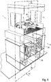
- the invention relates in particular to a system for coating workpieces 1 in the form of bodies 6, as shown in a first exemplary embodiment.
- This system comprises an air duct system 2 and a work area (paint booth 3).
- a separating device 4 according to the invention is provided adjacent to the painting booth 3, in particular below it.
- the air duct system 2 guides a gas flow 5 through the painting booth 3 and the separation device 4.
- the air duct system 2 comprises a fan 7 and a conditioning device 8.
- the fan 7 conveys the gas flow 5 through the painting booth 3 and the separating device 4. At least part of the gas flow 5 is also passed through the conditioning device 8, with a view to temperature and / or Moisture conditioned.
- the painting booth 3 comprises a conveying device 9 for conveying a body 6 and an application device 10 for applying paint to a body 6.
- an application device 10 for applying paint to a body 6.
- solid, liquid and / or pasty particles in the form of paint overspray particles 11 get in the gas flow 5.
- a gas flow 5 enriched with paint overspray particles 11 is preferably a raw gas flow 12.
- the separator 4 has a pre-separator, a main separator and a post-separator.
- the raw gas stream 12 first passes the pre-separator and then one after the other the main separator and the post-separator.
- the raw gas stream 12 has a higher number of paint overspray particles 11 when it enters the separation device 4 than it does when it exits the separation device 4.
- a gas stream 5 exiting from the separation device 4 is preferably a clean gas stream 36.
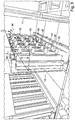
- the pre-separator is designed as an impact separator 13 and comprises eight structurally identical separator elements 14, 15, 16, 17, 18, 19, 20, 21 and one Regeneration device 22. Outer contours of adjacent separation elements 14, 15, 16, 17, 18, 19, 20, 21 intersect.
- the regeneration device 22 temporarily acts on a separation element and paint overspray particles 11 deposited thereon.
- the impact separator 13 also has at least two different zones arranged on a separation element, firstly a separation zone 23 and secondly a regeneration zone 24.
- a first separating element 15 of the impact separator 13 comprises a shaft 25 and eight structurally identical radial surface elements 15a, 15b, 15c, 15d, 15e, 15f, 15g, 15h, which are arranged protruding radially from the shaft 25.
- a (first) radial surface element 15a has two separation surfaces 15a 'and 15a ".
- a second radial surface element 15b has two separation surfaces 15b' and 15b" and a third radial surface element 15c has two separation surfaces 15c 'and 15c ".
- the other radial surface elements of the Separation element also has two separation surfaces.
- the remaining separation elements 14, 16, 17, 18, 19, 20, 21 are constructed in the same way as the first separation element 15.
- the separation surfaces of separation elements 14, 16 adjacent to the first separation element 15 are at a distance from the separation surfaces 15a ', 15a ", 15b', 15b", 15c ', 15c "of the first separation element 15.
- a (first) drive unit 27 is in a non-positive connection with the shaft 25.
- the first separating element 15 can change its position and assume at least two different working positions.
- the regeneration device 22 arranged downstream of a separation element comprises a cleaning system 29.
- the cleaning system 29 serves to remove paint overspray particles 11 from a separation surface.
- the cleaning system 29 has eight cleaning stamps 30a, 30b, 30c, 30d, 30e, 30f, 30g, 30h, which are arranged on a carrier device 31.
- the cleaning system 29 comprises a second drive unit 32, which is operatively connected to at least one cleaning ram, and a collecting container 33.
- the collecting container 33 is arranged below a separation element.
- At least one cleaning stamp is assigned to each of the separation elements.
- a first cleaning stamp 30b for example, is assigned to the first separation element 15.
- the main separator is designed as a filter fleece 34 and is arranged downstream of the pre-separator.
- the filter fleece 34 comprises a multiplicity of fiber elements and, due to its porous structure, the gas flow 5 and / or the raw gas flow 12 can flow through it.
- the post-separator is designed as a pocket filter 35 and is arranged downstream of the main separator.
- the gas stream after passing through the main separator, is fed to a conditioning device and then again to the painting booth.
- a post-separator is optionally available.
- the separation device 4 functions as follows.
- the raw gas stream 12 flows through the impact separator 13 in the main flow direction 28, at least some of the paint overspray particles 11 contained in the raw gas stream 12 being separated off.
- At least a partial flow of the raw gas flow 12 passes the first separation element 15 and at the same time the area between the first separation element 15 and a separation element 16 arranged adjacent to it, in which the outer contours of the two separation elements 15, 16 intersect.
- a first separation surface 15c ′′ assigned to the third radial surface element 15c is arranged in the separation zone 23 and a second separation surface 15a ′′ assigned to the first radial surface element 15a is arranged in the regeneration zone 24.
- the first separation surface 15c "a separation position and the second separation surface 15a" a regeneration position.
- the first separation surface 15c ′′ positioned in the separation zone 23 acts as a flow guide element when the raw gas flow 12 flows through the impact separator 13.
- a flow guide element deflects the raw gas flow 12 at certain points from the main flow direction 28 into a secondary flow direction 37
- Paint overspray particles 11 continue to follow the main flow direction 28 due to inertia effects and collide with the first separation surface 15c ′′. Paint overspray particles 11 are first deposited on the first separation surface 15c ′′ and are then physically bound to the first separation surface 15c ′′ by means of adhesion and cohesion forces. This at least temporary interaction between at least some of these paint overspray particles 11 and the first separation surface 15c ′′ removes these paint overspray particles 11 from the raw gas flow 12.
- paint overspray particles 11 are deposited on the first separation surface 15c ′′ of the first separation element positioned in the separation zone 23, paint overspray particles 11 are simultaneously removed from a second separation surface 15a ′′ of the same first separation element 15 positioned in the regeneration zone 24.
- the cleaning stamp 30b strips off paint overspray particles 11 that were previously deposited on the second separation surface 15a ′′. Stripped paint overspray particles 11 fall into the collecting container 33.
- the cleaning stamp 30b is returned to a Brought to the starting position.
- a second (not shown) working position in which the first separation element 15 is arranged rotated by 90 ° about the axis of rotation 26, the first separation surface 15c ′′ is arranged in the regeneration zone 24 and the second separation surface 15a ′′ in the Separation zone 23.
- the first separation surface 15c "assumes a regeneration position and the second separation surface 15a" assumes a separation position.
- the first separation element 15 is adjusted between a first and a second working position by rotating it about the axis of rotation 26. When the first separation element 15 is rotated completely through 360 °, a separation surface of the first separation element 15 passes through the separation zone 23 at least once and the regeneration zone 24 at least once .
- a collecting container has an insert made of cardboard, which reduces contamination of the collecting container.
- Such an insert preferably fits positively into the collecting container and can be removed for cleaning purposes.
- a pre-separator has a single separating element with a plurality of separating surfaces.
- the raw gas stream 12 flows through the filter fleece 34. At least some of the paint overspray particles 11 that have passed through the impact separator 13 are separated out.
- the raw gas stream 12 flows through the pocket filter 35.
- the paint overspray particles 11 that have passed through the impact separator 13 and the filter fleece 34 are separated.
- a gas stream 5 that has passed the separation device 4 is preferably a pure gas stream 36.
- a portion of the clean gas flow 36 is removed from the clean gas flow 36 as exhaust air flow 38 and a fresh air flow 39 is fed to the clean gas flow 36.
- the clean gas stream 36 then flows through the Conditioning device 8.
- the pure gas stream 36 is then fed again to the painting booth 3 as gas stream 5.
- a pre-separator serves to protect a downstream main and / or post-separator.
- the pre-separator removes some of the paint overspray particles 11 from the raw gas flow 12, so that the main separator and / or the post-separator have to separate out fewer paint overspray particles 11. Thereby the main and / or the post-separator can be relieved, and the service life of the main separator and / or the post-separator can be extended.
- a separation element of a pre-separator comprises a plurality of radial surface elements with a plurality of separation surfaces which are provided with a plurality of passage openings.
- the passage openings are arranged on the separation surfaces in such a way that a raw gas flow which passes the pre-separator and hits the separation surface in the process passes through these passage openings. Particles contained in the raw gas flow, in particular paint overspray particles, are deposited on the separation surface.
- the passage openings are therefore located in the flow path of the raw gas flow.
- a separation surface with a passage opening filters particles contained in the raw gas flow out of the raw gas flow, in that the passage opening for gaseous components of the raw gas flow can be passed, while solid and / or liquid components such as particles and / or paint overspray particles are at least partially separated on the separation surface.
- a separation surface is preferably formed from a polymer, a ceramic and / or a metallic material.
- the passage openings can be through bores in a solid material, through intermediate spaces and / or material-free spaces in a sintered material and / or be formed by intermediate spaces and / or material-free spaces in a fibrous tissue material.
- a perforated plate, a foam, a fiber mat, an expanded metal, a sintered metal, a sintered ceramic and / or a sintered plastic can be provided here.
- FIG. 7 and 8th The illustrated second embodiment of a separation device 4 differs from that in FIG Figures 1 to 6 illustrated first embodiment essentially by a differently designed cleaning system.
- a cleaning system essentially comprises a blasting device 40, with the aid of which a blasting agent can be brought into interaction with a separation surface.
- the blasting device 40 has a carrier system 43, several blasting nozzles 41 attached to the carrier system 43 and a unit for supplying blasting media 42.
- the blasting agent supply unit 42 comprises a storage container and conveys the blasting agent from this storage container to a blasting nozzle 41.
- a blasting nozzle 41 is aligned with a separation element in such a way that a jet emerging from the blasting nozzle 41 strikes the separation element.
- Solid carbon dioxide (so-called dry ice) is used as the blasting agent.
- the blasting agent is put under pressure in the blasting device 40 and leaves the blasting device 40 via a blasting nozzle 41.
- the separating device in a system for coating workpieces 1 according to embodiment 2 functions as follows.
- a separation surface 15a ′′ is arranged in a separation position in a separation zone 23 and picks up paint overspray particles 11 which are separated from a raw gas stream 12.
- the separation element 15 rotates about the axis of rotation 26 into a different, second working position (not shown).
- the separation surface 15a ′′ is arranged in a regeneration position in a regeneration zone 24.
- the abrasive is the blasting device 40 is released into space via a blasting nozzle 41. Due to the kinetic energy stored in the blasting media and the alignment of the blasting nozzle 41, the blasting media moves in the direction of the separation surface 15a ".
- this kinetic energy is transferred at least in part by the blasting media to those paint overspray particles 11 which are on the separation surface 15a" have been deposited, and removes these paint overspray particles 11 from the separation surface 15a ".
- the separation element 15 can be brought into a third working position by a further rotation (in the same or opposite direction) around the axis of rotation 26, in which the separation surface 15a" is again arranged in a separation zone 23 and can be subjected to a separation process.
- compressed air is used as a blasting agent as an alternative or in addition to dry ice.
- the components of the compressed air essentially nitrogen and oxygen molecules, are released via a jet nozzle and then hit a separation surface on which paint overspray particles have previously been separated.
- a cleaning system has a jet nozzle that is movably arranged and can be positioned by adjustment in such a way that this jet nozzle can first remove paint overspray particles from a first area of a separation surface and then paint overspray particles from another area of the same separation surface.
- a cleaning system has an additional drive unit for moving one or more jet nozzles.
- a cleaning system has a jet nozzle which is movably arranged and can be positioned by adjusting in such a way that this jet nozzle can first remove paint overspray particles from a separation surface of a separation element and then paint overspray particles from a separation surface of another separation element.
- FIG. 9 and Figure 10 The illustrated third exemplary embodiment of a separation device 4 differs essentially from the first exemplary embodiment in that a regeneration device has an auxiliary material system 44 in addition to a cleaning system.
- An auxiliary material system 44 serves to apply an auxiliary material to a deposition surface of a deposition element.
- the auxiliary material system 44 comprises a unit for supplying auxiliary material 45 and a plurality of auxiliary material nozzles 46 attached to a holding device.
- the unit for supplying auxiliary material 45 comprises a storage container and conveys auxiliary material from this storage container to an auxiliary material nozzle 46.
- Limestone powder is used as an auxiliary material. Limestone powder particles physically interact with paint overspray particles on contact.
- the separation device according to embodiment 3 functions as follows.
- a first separation surface is arranged in a regeneration zone and a second separation surface is arranged in a separation zone.
- Limestone powder particles are applied to the first separation surface by means of an auxiliary material nozzle 46.
- Limestone powder particles preferably form a separating layer between a separation surface and paint overspray particles.
- paint overspray particles are deposited on the second separation surface, which are part of a raw gas flow that passes through the separation device.
- the separation element After a certain time, the separation element is moved into a second working position so that the first separation surface is arranged in a separation zone and paint overspray particles can be separated on it.
- the cleaning system limestone dust particles and paint overspray particles are removed from the second separation surface, which is arranged in a regeneration zone.
- powdered limestone particles are then again applied to the second separation surface as a separating layer.
- a spray film is used as an auxiliary material instead of limestone powder particles.
- a spray film contains one or more liquid ones Components that are applied to a deposition surface and form a layer there by running.
- a physical and / or chemical reaction of a component optionally with another component and / or a reaction gas, e.g. air, a solid, film-like substance is formed, which acts as a separating layer between a separation surface and a paint overspray particle and in a regeneration step can be deducted.
- a fat is used as an auxiliary material.
- the fat preferably comprises one or more hydrocarbon compounds which are solid and / or viscous at room temperature.
- the fat can, for example, be atomized by means of pressure and applied to a radial surface element of a separation element with the aid of an auxiliary material nozzle.
- the applied grease acts as a separating layer between the radial surface element and the paint overspray particles and facilitates cleaning of the radial surface element.
- a cleaning system is used which acts, for example, physically and / or chemically on the separated paint overspray particles and / or the grease.
- Such a cleaning system preferably comprises a cleaning stamp and / or a jet device for applying a cleaning fluid such as water, alcohol and / or compressed air.
- the separation surfaces include a plurality of passage openings, the separation surfaces being at least temporarily provided with an auxiliary material when the separation device is in operation and can be cleaned with the aid of a cleaning system.
- FIG. 11 The fourth embodiment of a separation device 4 shown differs from that in FIG Figures 1 to 9 illustrated embodiments essentially in that several separation elements are arranged in different depth positions.
- a vertically oriented primary auxiliary plane 47 is laid through the separating device 4.
- a first group of separation elements 49 is arranged in the primary auxiliary plane 47, the axes of rotation of the separation elements of this first group of separation elements 49 lie in the primary auxiliary plane 47.
- the first group of separation elements 49 comprises three separation elements.
- a vertically oriented secondary auxiliary plane 48 is also laid through the separating device 4.
- a second group of separation elements 50 is arranged in the secondary auxiliary plane 48, the axes of rotation of the separation elements of this second group of separation elements 50 lying in the secondary auxiliary plane 48.
- the second group of separation elements 50 comprises two separation elements.
- the primary auxiliary plane 47 and the secondary auxiliary plane 48 are arranged one after the other in the main flow direction 28 as well as parallel and at a certain distance from one another.
- a raw gas stream 12 which flows through the separation device 4 in the main flow direction 28, first crosses the primary auxiliary plane 47 and then the secondary auxiliary plane 48. If separating elements are arranged in a separating device in different depth positions, more separating elements can be arranged in the separating device with the same width of the separating device or, if the separating device is smaller, the same number of separating elements can be arranged in the separating device than if separating elements are arranged in a deep position.
- a second group of separation elements arranged in the second auxiliary plane is designed to be displaceable on an axis arranged parallel to the main flow direction.
- the distance between a first group of separation elements arranged in the primary auxiliary plane on the one hand and a second group of separation elements arranged in the secondary auxiliary plane on the other hand changes. If a group of separation elements is designed to be displaceable in this way, a distance between several groups of separation elements can be increased, for example, at least temporarily. This increases the distance between a separation surface of a separation element of the one group of separation elements and a separation surface of a separation element of the other group of separation elements.
- FIG. 12 An in Figure 12
- the illustrated fifth embodiment of a separation device 4 differs from that in FIG Figures 1 to 11 illustrated embodiments essentially in that four separation elements are provided. Furthermore, the separating device 4 differs in that the separating elements are designed alternatively.
- Such a first alternative embodiment of a separation element 51 has, in particular, a plurality of surface elements 54 ', 54 ", 54"' with separation surfaces arranged differently.
- a first differently arranged separation surface 52 'and a second differently arranged separation surface 52 "arranged in the main flow direction 28 after the first differently arranged separation surface 52' have a largely parallel alignment to one another.
- a third differently arranged separation surface 52 '" has a largely vertical orientation the two aforementioned separation surfaces.
- the first alternative embodiment of a separation element 51 is changed from the first to a second working position by rotating about an axis of rotation 26 adjusted. After this rotation, the first differently arranged separation surface 52 'and the second differently arranged separation surface 52 "are positioned in the regeneration zone 24, and the third differently arranged separation surface 52"' in the separation zone 23. While of the first differently arranged separation surface 52 'and the second differently arranged separation surface 52 "paint overspray particles 11 are removed, are deposited on the third differently arranged separation surface 52" paint overspray particles 11.
- FIG. 13 An in Figure 13 The illustrated sixth embodiment of a separation device 4 is arranged in a system for coating workpieces 1, which, in contrast to the previous embodiments, is used to paint parts and / or add-on parts of car bodies, such as hoods, doors, side parts, front flaps, tailgates, bumpers and / or exterior mirror housings.
- the separation device 4 differs from that in FIG Figures 1 to 12 illustrated embodiments essentially by a second alternative configuration of a separation element 53. In the separation device 4 according to embodiment 6, three separation elements of a second alternative configuration are provided.
- Such a second alternative embodiment of a separation element 53 has in particular a shaft 25, several differently configured radial surface elements 55 and several differently configured separation surfaces 56.
- a differently configured radial surface element 55 is arranged so as to project radially on the shaft 25.
- a retaining element 57 is provided at an end of the differently configured radial surface element 55 opposite to the shaft 25, .
- the retaining element 57 protrudes at an angle of 45 ° to 90 °, preferably perpendicular, from the radial surface element 55 configured differently.
- a retaining element 57 acts as a barrier for a raw gas flow 12 passing through the separating device 4 and for paint overspray particles 11 deposited on a differently configured separation surface 56 of the differently configured radial surface element 55.
- the retaining element 57 at least partially prevents paint overspray particles 11 from being separated from the raw gas flow 12 flowing past get carried away.
- FIG. 14 The illustrated seventh embodiment of a separation device 4 differs from that in FIG Figures 1 to 13 illustrated embodiments essentially by a third alternative embodiment of a separation element 58.
- a first alternatively arranged axis of rotation 59 is aligned parallel to a central longitudinal axis 60 of the separation element and is arranged at a certain distance from this central longitudinal axis 60.
- separating elements are arranged in a row and are rotated about their respective axis of rotation, the axes of rotation arranged offset with respect to a central longitudinal axis cause a varying distance between the separating elements.
- a flow velocity and / or a pressure loss of the raw gas flow 12 and / or a degree of separation of the impact separator 13 can thus be influenced.
- a further alternative embodiment of a separation element has an axis of rotation which intersects a central longitudinal axis of the separation element at a point within an outer contour of the separation element.
- an axis of rotation of a separating element is designed to be adjustable with respect to the position and / or the alignment.
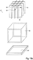
- FIG. 15a and 15b The eighth embodiment of a separation device 4 shown differs from that in FIG Figures 1 to 14 illustrated embodiments essentially in that a folded cardboard filter 61 is provided as the main separator.
- a plurality of folded cardboard filters 61 are arranged next to and above one another in a grid; in the exemplary embodiment described here, there are nine folded cardboard filters 61 overall, arranged in a grid with three folding cardboard filters 61 next to one another and three folding cardboard filters 61 one above the other.
- a folded cardboard filter 61 comprises an inner element 62 and an outer element 63 and optionally a tub element 64, an inner element 62 being temporarily arranged within an outer element 63 and an outer element 63 being arranged temporarily in a tub element 64.
- An inner element 62 has a wall section 65 with a plurality of passage and / or deflection openings 66.
- the raw gas stream 12 flows through the passage and / or deflection openings 66, while paint overspray particles 11 are deposited on closed partial areas of a wall section 65.
- the raw gas stream 12 enters the folded cardboard filter 61 in a main flow direction 28, passes through it and is deflected several times. During the deflection, paint overspray particles 11 are deposited on a closed partial area of a wall section 65 of the folded cardboard filter 61 with the aid of inertia effects.
- a folded cardboard filter 61 If the separation effect of a folded cardboard filter 61 is reduced and / or exhausted, it is removed from the separation device 4 and replaced by a new folded cardboard filter 61 or by a cleaned and / or processed folded cardboard filter 61.
- several folded cardboard filters are arranged one after the other in the main flow direction, so that a raw gas stream flows through the folded cardboard filters one after the other.
- a folded cardboard filter is conical.
- a vertical cross-sectional area of the folded cardboard filter decreases in the main flow direction.
- a main separator preferably has a receptacle device that is negative in relation to the folded cardboard filter.
- a folded cardboard filter designed in this way can be due to a centering effect caused by the conical shape particularly easy to install in the main separator and to be removed from it again.
- a system with rigid-body filter elements can be used as the main separator, with rigid-body filter elements preferably being made of a polymer material.
- Rigid filter elements act as regenerable surface filters, the surface of which can be protected from paint overspray particles with a barrier layer formed from an auxiliary material.
- an electrostatic wet separation system can be used as the main separator. Paint overspray particles are first electrically charged using a corona electrode and then deposited on a grounded separation electrode.
- an electrostatic wet separation system has a liquid system that contains a substance and / or a mixture of substances with liquid, waxy and / or includes pasty components.
- the substance and / or the mixture of substances wet the separation electrode and absorb paint overspray particles that strike it.
- the substance is preferably a release agent.
- a main separator designed as a hybrid filter is used.
- a hybrid filter has several differently acting partial separation systems and, in addition to a cardboard material, comprises a fibrous plastic material and a wood material.
- Partial separation systems with different effects are formed from the cardboard material and from the fibrous plastic material, which, for example, can separate paint overspray particles of different particle sizes to different degrees.
- a first partial separation system comprises a surface filter, on the surface of which paint overspray particles can be separated.
- a second partial separation system comprises a depth filter that can absorb paint overspray particles into its interior.
- the wood material fulfills a support and stabilization function and preferably reinforces the hybrid filter.
- a separation device is arranged only on one side of an auxiliary plane configured as a vertical longitudinal center plane of a coating installation.
- auxiliary plane configured as a vertical longitudinal center plane of a coating installation.
- a separation surface is formed from a ferromagnetic material in the form of a steel alloy and has a magnetic coil.
- An auxiliary material for protecting the separation surface then comprises in particular a ferromagnetic material in the form of iron powder.
- the separation device comprises a jet device with which a jet of compressed air can be directed onto the separation surface.
- a separation surface is designed from a hard magnetic material in the form of an iron alloy.
- An auxiliary material for protecting the separation surface then comprises in particular a ferrofluid in the form of a colloidal suspension of iron in water.
- the separation device comprises a cleaning stamp in order to remove separated paint overspray particles and auxiliary material from the separation surface.
- the cleaning ram is moved along the separation surface.
- a separation surface is covered with a film material.
- a film material acts as a separating layer between a separation surface and paint overspray particles. At certain time intervals, a film material together with the paint overspray particles deposited on it can be removed from the separation surface and replaced by new, fresh and / or cleaned film material.
- a cardboard material can be used as an alternative or in addition to a film material.
- a separating element is arranged lying horizontally in a preseparator. A main flow direction of a raw gas flow through the pre-separator is then oriented essentially vertically.
- a perforated plate is arranged downstream of a main separator, which has holes at certain points and which, with its external dimensions, fills the free cross section of the separating device.
- the perforated plate causes a more even flow through the separation device.
Description
Die vorliegende Erfindung betrifft eine Abscheidevorrichtung zum Abscheiden von Partikeln aus einem Rohgasstrom, wobei im Rohgasstrom ein Anteil fester, flüssiger und/oder pastöser Partikel mitgeführt wird. Der Rohgasstrom passiert die Abscheidevorrichtung in einer Hauptdurchströmungsrichtung, und weist einen Hauptabscheider auf, der wenigstens einen Teil der Partikel aus dem Rohgasstrom abscheidet, wobei der Rohgasstrom den Hauptabscheider in der Hauptdurchströmungsrichtung durchströmt und als Reingasstrom aus dem Hauptabscheider austritt.The present invention relates to a separation device for separating particles from a raw gas flow, a proportion of solid, liquid and / or pasty particles being carried along in the raw gas flow. The raw gas flow passes through the separation device in a main flow direction and has a main separator which separates at least some of the particles from the raw gas flow, the raw gas flow flowing through the main separator in the main flow direction and exiting the main separator as a clean gas flow.
Eine Abscheidevorrichtung zum Abscheiden von Partikeln ist beispielsweise aus der
Eine Abscheidevorrichtung zum Abscheiden von Partikeln ist außerdem aus der
Der vorliegenden Erfindung liegt die Aufgabe zugrunde, eine Abscheidevorrichtung bereitzustellen, deren Hauptabscheider eine hohe Standzeit aufweist. Eine solche Abscheidevorrichtung soll außerdem günstig betreibbar sein durch Regenerierung im Betrieb.The present invention is based on the object of providing a separating device whose main separator has a long service life. Such a separation device should also be able to be operated inexpensively by regeneration during operation.
Zur Lösung der Aufgabe wird erfindungsgemäß eine gattungsgemäße Abscheidevorrichtung zum Abscheiden von Partikeln aus einem Rohgasstrom vorgeschlagen, die einen Vorabscheider zum Abscheiden wenigstens eines Teils der Partikel aus dem Rohgasstrom aufweist, der derart stromaufwärts zum Hauptabscheider angeordnet ist, dass der Rohgasstrom in der Hauptdurchströmungsrichtung zuerst den Vorabscheider und nachfolgend den Hauptabscheider durchströmt. Der Vorabscheider umfasst ein Abscheideelement, welches zur Umlenkung des Rohgasstroms vorgesehen ist, wobei das Abscheideelement eine Welle sowie ein Radialflächenelement umfasst, das radial von der Welle abstehend an der Welle angeordnet ist, und welches eine an dem Radialflächenelement angeordnete Abscheidefläche aufweist, an der Partikel aus dem Rohgasstrom abgeschieden werden können. Außenkonturen zweier zueinander benachbart angeordneter Abscheideelemente schneiden sich, und die Abscheideflächen zweier zueinander benachbart angeordneter Abscheideelemente weisen einen Abstand zueinander auf. Die Außenkontur eines Abscheideelements ist bevorzugt die Oberfläche eines fiktiven näherungsweise zylinderförmig und/oder prismenförmig ausgebildeten Körpers. Ein Abscheideelement ist kontinuierlich oder intervallweise um eine Rotationsachse drehbar ausgestaltet, um das Abscheideelement zwischen mehreren Arbeitspositionen zu verstellen. Dabei weist das Abscheideelement mindestens zwei Abscheideflächen zum Abscheiden von Partikeln auf, wobei in einer ersten Arbeitsposition des Abscheideelements eine Abscheidefläche des Abscheideelements sich in einer Abscheidestellung befindet, während gleichzeitig eine andere Abscheidefläche desselben Abscheideelements sich in einer Regenerierungsstellung befindet. Eine Abscheidefläche des Abscheideelements wirkt in Abscheidestellung als Strömungsleitelement, das in den Strömungsweg des Rohgasstroms hineinragt, wobei mindestens je eine als Strömungsleitelement wirkende Abscheidefläche zweier benachbart angeordneter Abscheideelemente gemeinsam eine Ablenkung des Rohgasstroms von der Hauptdurchströmungsrichtung bewirken, wodurch die im Rohgasstrom enthaltenen Partikel durch Massenträgheit bedingt an den Abscheideflächen abgeschieden werden, wobei die Abscheideflächen zweiter benachbart angeordneter Abscheideelemente in der Hauptdurchströmungsrichtung derart hintereinander angeordnet sind, dass sie nacheinander vom Rohgasstrom überstrichen werden.To achieve the object, a generic separation device for separating particles from a raw gas stream is proposed according to the invention, which one Pre-separator for separating at least a part of the particles from the raw gas flow, which is arranged upstream of the main separator in such a way that the raw gas flow in the main flow direction first flows through the pre-separator and then through the main separator. The pre-separator comprises a separator element which is provided for deflecting the raw gas flow, the separator element comprising a shaft and a radial surface element which is arranged on the shaft protruding radially from the shaft and which has a separation surface arranged on the radial surface element from which particles the raw gas stream can be deposited. Outer contours of two separation elements arranged adjacent to one another intersect, and the separation surfaces of two separation elements arranged adjacent to one another are spaced apart from one another. The outer contour of a separating element is preferably the surface of a fictitious approximately cylindrical and / or prism-shaped body. A separating element is designed to be rotatable continuously or at intervals about an axis of rotation in order to adjust the separating element between several working positions. The separation element has at least two separation surfaces for separating particles, with one separation surface of the separation element being in a separation position in a first working position of the separation element, while at the same time another separation surface of the same separation element is in a regeneration position. In the separation position, a separation surface of the separation element acts as a flow guide element that protrudes into the flow path of the raw gas flow, with at least one separation surface each acting as a flow guide element of two adjacently arranged separation elements jointly causing a deflection of the raw gas flow from the main flow direction, whereby the particles contained in the raw gas flow due to inertia the separation surfaces are deposited, the separation surfaces of second adjacently arranged separation elements being arranged one behind the other in the main flow direction in such a way that they are swept over by the raw gas flow one after the other.
Beim Rohgasstrom handelt es sich um einen Gasstrom, insbesondere um einen Luftstrom, der zumindest zeitweise gewisse Partikel mit sich führt. Der Gasstrom wird beispielsweise in einem Arbeitsbereich mit solchen Partikeln beladen und strömt als Rohgasstrom vom Arbeitsbereich zur Abscheidevorrichtung und durch diese hindurch. In der Abscheidevorrichtung wird der Rohgasstrom entladen, gereinigt und/oder recycliert. Dabei werden Partikel aus dem Rohgasstrom entfernt.The raw gas flow is a gas flow, in particular an air flow, which at least at times carries certain particles with it. The gas flow is loaded with such particles, for example in a work area, and flows off as a raw gas flow Working area to and through the separation device. The raw gas stream is discharged, cleaned and / or recycled in the separation device. Particles are removed from the raw gas flow.
Nachdem der Rohgasstrom entladen, gereinigt und/oder recycliert worden ist, strömt er zunächst als Reingasstrom von der Abscheidevorrichtung in eine optional vorhandene Konditioniervorrichtung und anschließend als Gasstrom in den Arbeitsbereich, um dort erneut Partikel aufzunehmen. Ein Reingasstrom und/oder ein Gasstrom weisen insbesondere eine geringere Anzahl an Partikeln auf als der Rohgasstrom. Optional enthalten der Reingasstrom und/oder der Gasstrom nach Durchströmen der Abscheidevorrichtung keine solchen Partikel mehr, die im Arbeitsbereich in den Rohgasstrom gelangt sind.After the raw gas stream has been discharged, cleaned and / or recycled, it first flows as a clean gas stream from the separation device into an optionally available conditioning device and then as a gas stream into the work area in order to pick up particles there again. Have a clean gas flow and / or a gas flow in particular a smaller number of particles than the raw gas stream. Optionally, after flowing through the separation device, the clean gas flow and / or the gas flow no longer contain any particles that have entered the raw gas flow in the working area.
Die im Rohgasstrom enthaltenen Partikel umfassen festes, gasförmiges, flüssiges und/oder pastöses Material und/oder ein Stoffgemisch. Feste, flüssige und/oder pastöse Partikel bilden zusammen mit dem Gasstrom ein Aerosol. Bei Partikeln handelt es sich insbesondere um Lackoverspray-Teilchen, bevorzugt um Tröpfchen, die beim Applizieren einer Flüssigkeit auf ein im Arbeitsbereich angeordnetes Werkstück in den Gasstrom und/oder den Rohgasstrom gelangen.The particles contained in the raw gas stream comprise solid, gaseous, liquid and / or pasty material and / or a mixture of substances. Solid, liquid and / or pasty particles form an aerosol together with the gas flow. Particles are in particular paint overspray particles, preferably droplets, which get into the gas flow and / or the raw gas flow when a liquid is applied to a workpiece arranged in the work area.
Die Partikel werden vom Gasstrom und/oder vom Rohgasstrom vorzugsweise mitgenommen und in Strömungsrichtung räumlich verlagert. Mittels der Abscheidevorrichtung wird wenigstens ein Teil der Partikel aus dem Gasstrom und/oder dem Rohgasstrom entfernt.The particles are preferably carried along by the gas flow and / or the raw gas flow and are spatially displaced in the direction of flow. At least some of the particles are removed from the gas flow and / or the raw gas flow by means of the separation device.
Die Abscheidevorrichtung weist einen Vorabscheider sowie einen Hauptabscheider auf und entfernt Partikel aus dem Rohgasstrom, insbesondere solche Partikel, die in einem Arbeitsbereich von einem Gasstrom, einem Reingasstrom und/oder vom Rohgasstrom aufgenommen worden sind.The separator has a pre-separator and a main separator and removes particles from the raw gas flow, in particular those particles which have been taken up in a working area by a gas flow, a clean gas flow and / or the raw gas flow.
Optional weist die Abscheidevorrichtung zusätzlich zu einem Vorabscheider und einem Hauptabscheider einen Nachabscheider auf, der Partikel abscheiden kann, die den Vorabscheider und den Hauptabscheider passiert haben.Optionally, in addition to a pre-separator and a main separator, the separating device has a post-separator which can separate particles that have passed through the pre-separator and the main separator.
Ein Arbeitsbereich umfasst beispielsweise eine Lackierkabine, in der ein Werkstück lackiert wird, und wird von einem Gasstrom durchströmt.A work area comprises, for example, a painting booth in which a workpiece is painted, and a gas flow flows through it.
Der Rohgasstrom enthält nach Durchströmen der Abscheidevorrichtung bevorzugt eine geringere Anzahl an Partikeln als vor dem Eintritt in die Abscheidevorrichtung. Optional enthält der Rohgasstrom nach Durchströmen der Abscheidevorrichtung keine Partikel mehr, vorzugsweise keine solchen Partikel mehr, die im Arbeitsbereich in den Rohgasstrom gelangt sind. Ein derart gereinigter Rohgasstrom wird als Reingasstrom bezeichnet und kann insbesondere zumindest teilweise erneut einem Arbeitsbereich, insbesondere demselben oder einem oder mehreren anderen Arbeitsbereichen, zugeführt werden, um dort Partikel aufzunehmen.After flowing through the separation device, the raw gas stream preferably contains a smaller number of particles than before entering the separation device. Optionally, after flowing through the separation device, the raw gas stream no longer contains any particles, preferably no longer any particles that have entered the raw gas stream in the working area. A raw gas stream purified in this way is referred to as a clean gas stream and can in particular at least partially fed back to a work area, in particular the same or one or more other work areas, in order to pick up particles there.
Der Hauptabscheider ist vorzugsweise als Einweg-System, als Mehrweg-System und/oder als Dauerfilter ausgebildet. Der Hauptabscheider umfasst zum Beispiel ein keramisches, ein metallisches und/oder ein polymeres Material mit einer Gitterstruktur und/oder mit poröser Konsistenz. Der Hauptabscheider scheidet im Rohgasstrom enthaltene Partikel wenigstens teilweise, vorzugsweise vollständig, aus dem Rohgasstrom ab. Ein Gasstrom tritt dabei als Rohgasstrom in den Hauptabscheider ein, passiert diesen und tritt als Rohgasstrom und/oder als Reingasstrom aus dem Hauptabscheider aus. Optional wird ein Reingasstrom dem Arbeitsbereich anschließend erneut zugeführt.The main separator is preferably designed as a disposable system, a reusable system and / or a permanent filter. The main separator comprises, for example, a ceramic, a metallic and / or a polymer material with a lattice structure and / or with a porous consistency. The main separator separates particles contained in the raw gas flow at least partially, preferably completely, from the raw gas flow. A gas flow enters the main separator as a raw gas flow, passes it and exits the main separator as a raw gas flow and / or as a clean gas flow. Optionally, a stream of clean gas is then fed back into the work area.
Der Vorabscheider ist stromaufwärts zum Hauptabscheider angeordnet und scheidet wenigstens einen Teil der im Rohgasstrom enthaltenen Partikel aus dem Rohgasstrom ab. Bei Verwendung einer Abscheidevorrichtung, die einen Vorabscheider und einen Hauptabscheider aufweist, ist der Anteil an Partikeln im Rohgasstrom bei Eintritt des Rohgasstroms in den Hauptabscheider vorzugsweise geringer als bei Verwendung einer Abscheidevorrichtung ohne Vorabscheider. Damit wird eine Belastung des Hauptabscheiders reduziert.The pre-separator is arranged upstream of the main separator and separates at least some of the particles contained in the raw gas flow from the raw gas flow. When using a separator which has a pre-separator and a main separator, the proportion of particles in the raw gas flow when the raw gas flow enters the main separator is preferably lower than when using a separating device without a pre-separator. This reduces the load on the main separator.
Als Hauptdurchströmungsrichtung ist eine Richtung definiert, in der der Rohgasstrom die Abscheidevorrichtung im Wesentlichen passiert. Vorzugsweise sind der Vorabscheider und der Hauptabscheider derart angeordnet, dass der Rohgasstrom in Hauptdurchströmungsrichtung zunächst den Vorabscheider und nachfolgend den Hauptabscheider passiert.A direction in which the raw gas flow essentially passes through the separation device is defined as the main flow direction. The pre-separator and the main separator are preferably arranged in such a way that the raw gas stream first passes the pre-separator and then the main separator in the main flow direction.
Bevorzugt sind der Vorabscheider und der Hauptabscheider auf einer Achse angeordnet, die im Wesentlichen parallel zur Hauptdurchströmungsrichtung ausgerichtet ist.The pre-separator and the main separator are preferably arranged on an axis which is oriented essentially parallel to the main flow direction.
Eine Abscheidevorrichtung kann eine oder mehrere Hauptdurchströmungsrichtungen aufweisen, denen der Rohgasstrom wenigstens zeitweise folgt. Beispielsweise kann eine Hauptdurchströmungsrichtung eines Vorabscheiders von einer Hauptdurchströmungsrichtung eines Hauptabscheiders verschieden sein.A separation device can have one or more main flow directions which the raw gas stream follows at least temporarily. For example, a Main flow direction of a pre-separator can be different from a main flow direction of a main separator.
Alternativ oder zusätzlich können der Abscheidevorrichtung neben einer oder mehreren Hauptdurchströmungsrichtungen eine oder mehrere Nebenströmungsrichtungen zugeordnet sein, denen der Rohgasstrom beim Passieren der Abscheidevorrichtung wenigstens zeit- und/oder abschnittsweise folgt.As an alternative or in addition, one or more secondary flow directions can be assigned to the separation device in addition to one or more main flow directions, which the raw gas flow follows at least in time and / or in sections when passing through the separation device.
Eine mittlere Strömungsrichtung des Rohgasstroms beim Passieren der Abscheidevorrichtung entspricht im Wesentlichen der Hauptdurchströmungsrichtung.A mean direction of flow of the raw gas flow when passing the separation device essentially corresponds to the main direction of flow.
Das Abscheideelement ist derart im Strömungsweg des Rohgasstroms angeordnet, dass der den Vorabscheider passierende Rohgasstrom zumindest zum Teil von einer Hauptdurchströmungsrichtung abgelenkt wird, und beispielsweise wenigstens zeitweise einer Nebenströmungsrichtung folgt, die von der Hauptdurchströmungsrichtung abweicht.The separation element is arranged in the flow path of the raw gas flow in such a way that the raw gas flow passing through the pre-separator is at least partially diverted from a main flow direction and, for example, at least temporarily follows a secondary flow direction that deviates from the main flow direction.
Das Abscheideelement umfasst eine Welle sowie ein Radialflächenelement und/oder ein Flächenelement. Ein Radialflächenelement ist radial von der Welle abstehend an der Welle angeordnet.The separation element comprises a shaft and a radial surface element and / or a surface element. A radial surface element is arranged on the shaft protruding radially from the shaft.
Optional ist ein Radialflächenelement aus einem Material gebildet, das einen Elastizitätsmodul E aufweist, der zwischen 0,5 kN/mm2 und 1.000 kN/mm2, bevorzugt zwischen 5 und 250 kN/mm2, liegt. Ein Radialflächenelement aus einem derartigen Material kann vorteilhafterweise eine ausreichend hohe Biegesteifigkeit aufweisen, um nicht oder nur wenig vom auf das Radialflächenelement auftreffenden Rohgasstrom verbogen zu werden.Optionally, a radial surface element is formed from a material which has a modulus of elasticity E that is between 0.5 kN / mm 2 and 1,000 kN / mm 2 , preferably between 5 and 250 kN / mm 2 . A radial surface element made of such a material can advantageously have a sufficiently high flexural strength so that it is not or only slightly bent by the raw gas flow impinging on the radial surface element.
Die Abscheidefläche ist an dem Abscheideelement, insbesondere an einem Radialflächenelement und/oder Flächenelement des Abscheideelements angeordnet. Im Rohgasstrom enthaltene Partikel können wenigstens zeitweise mit der Abscheidefläche interagieren. Die Interaktion der Partikel mit der Abscheidefläche erfolgt wahlweise reversibel oder irreversibel. Dabei ist es möglich, Partikel chemisch und/oder physikalisch an die Abscheidefläche zu binden.The separation surface is arranged on the separation element, in particular on a radial surface element and / or surface element of the separation element. Particles contained in the raw gas stream can interact with the separation surface at least temporarily. The interaction of the particles with the separation surface is optionally reversible or irreversible. It is possible to bind particles chemically and / or physically to the separation surface.
Im Rohgasstrom enthaltene Partikel werden aus dem Rohgasstrom entfernt, wenn der Rohgasstrom beim Passieren des Vorabscheiders wenigstens zum Teil von der Hauptdurchströmungsrichtung abgelenkt wird und wenigstens zeitweise einer Nebenströmungsrichtung folgt. Die im Rohgasstrom enthaltenen Partikel folgen dabei aufgrund von Massenträgheit wenigstens zum Teil weiter der Hauptdurchströmungsrichtung, treffen auf der Abscheidefläche auf und werden dort abgeschieden.Particles contained in the raw gas flow are removed from the raw gas flow when the raw gas flow is at least partially diverted from the main flow direction when passing through the pre-separator and at least temporarily follows a secondary flow direction. Due to inertia, the particles contained in the raw gas flow continue to follow the main flow direction, at least in part, hit the separation surface and are separated there.
Vorzugsweise ist der Vorabscheider als ein Prallabscheider ausgestaltet, der eine Abscheidefläche aufweist, auf die gewisse Partikel aufprallen, und im Rohgasstrom enthaltene Partikel mittels Massenträgheit abscheidet.The pre-separator is preferably designed as an impact separator which has a separation surface on which certain particles impinge and which separates particles contained in the raw gas flow by means of inertia.
Die Außenkontur eines Abscheideelements ist bevorzugt die Oberfläche eines fiktiven näherungsweise zylinderförmig und/oder prismenförmig ausgebildeten Körpers. Dabei wird betrachtet, ob die Punkte des Abscheideelements, die am weitesten von einer zentralen Längsmittelachse des Abscheideelements entfernt liegen, mithin die äußersten Punkte des Abscheideelements, auf der Oberfläche eines Kreiszylinders oder eines polygonalen Prismas liegen.The outer contour of a separating element is preferably the surface of a fictitious approximately cylindrical and / or prism-shaped body. It is considered whether the points of the separation element which are the furthest away from a central longitudinal axis of the separation element, therefore the outermost points of the separation element, lie on the surface of a circular cylinder or a polygonal prism.
Ein Abscheideelement, dessen äußerste Punkte näherungsweise auf der Oberfläche eines Kreiszylinders liegen, weist näherungsweise eine (kreis-)zylinderförmige Außenkontur auf.A separator element, the outermost points of which are approximately on the surface of a circular cylinder, has approximately a (circular) cylindrical outer contour.
Ein Abscheideelement, dessen äußerste Punkte näherungsweise auf der Oberfläche eines polygonalen Prismas liegen, weist näherungsweise eine prismenförmige Außenkontur auf.A separation element, the outermost points of which lie approximately on the surface of a polygonal prism, has approximately a prism-shaped outer contour.
Wenn die Entfernung der Mittelpunkte zweier benachbarter Abscheideelemente, die beide näherungsweise eine zylinderförmige Außenkontur aufweisen, kleiner ist als die Summe der Radien dieser beiden Abscheideelemente, dann schneiden sich deren Außenkonturen bevorzugt in einem bestimmten Bereich des Vorabscheiders.If the distance between the centers of two adjacent separation elements, both of which have approximately a cylindrical outer contour, is smaller than the sum of the radii of these two separation elements, then their outer contours preferably intersect in a certain area of the pre-separator.
Der Abstand zwischen zwei Abscheideflächen benachbarter Abscheideelemente ist bevorzugt so groß, dass ein Rohgasstrom zwischen den zwei Abscheideflächen hindurchströmen kann.The distance between two separation surfaces of adjacent separation elements is preferably so great that a raw gas stream can flow through between the two separation surfaces.
Bevorzugt liegt der Abstand zwischen zwei Abscheideflächen benachbarter Abscheideelemente in einem Intervall zwischen 0,1 cm und 50 cm.The distance between two separation surfaces of adjacent separation elements is preferably in an interval between 0.1 cm and 50 cm.
Besonders bevorzugt liegt der Abstand zwischen zwei Abscheideflächen benachbarter Abscheideelemente in einem Intervall zwischen 1 cm und 20 cm.The distance between two separation surfaces of adjacent separation elements is particularly preferably in an interval between 1 cm and 20 cm.
In weiterer Ausgestaltung der Erfindung umfasst der Vorabscheider ein Abscheideelement, welches eine Durchlassöffnung zum Durchlassen eines Teils des Rohgasstroms aufweist. Der Rohgasstrom kann diese Durchlassöffnung passieren, wobei zumindest ein Teil von im Rohgasstrom enthaltenen Partikeln bevorzugt am Abscheideelement abgeschieden wird.In a further embodiment of the invention, the pre-separator comprises a separating element which has a passage opening for the passage of part of the raw gas flow. The raw gas flow can pass this passage opening, with at least some of the particles contained in the raw gas flow preferably being deposited on the separation element.
Eine Durchlassöffnung kann beispielsweise eine Bohrung in einem Abscheideelement umfassen und ist vorzugsweise in einem Radialflächenelement und/oder in einer Abscheidefläche angeordnet.A passage opening can, for example, comprise a bore in a separation element and is preferably arranged in a radial surface element and / or in a separation surface.
Alternativ oder zusätzlich kann ein Abscheideelement eine Vielzahl von Durchlassöffnungen, insbesondere eine Vielzahl von Bohrungen, zum Durchlassen eines Teils des Rohgasstroms aufweisen.Alternatively or additionally, a separation element can have a multiplicity of passage openings, in particular a multiplicity of bores, for the passage of part of the raw gas flow.
Ein Durchmesser einer Durchlassöffnung ist bevorzugt so gewählt, dass er kleiner ist als ein Durchmesser eines Partikels, bevorzugt kleiner als ein durchschnittlicher Durchmesser mehrerer Partikel.A diameter of a passage opening is preferably selected such that it is smaller than a diameter of a particle, preferably smaller than an average diameter of several particles.
Ein Abscheideelement weist optional eine Antriebseinheit auf, mittels der das Abscheideelement um eine Rotationsachse gedreht werden kann. Dabei kann eine Antriebseinheit mit einem oder mit mehreren Abscheideelementen in einer kraftschlüssigen Verbindung stehen. Alternativ oder zusätzlich zu einem Antrieb kann ein Abscheideelement eine Bremsvorrichtung aufweisen, mittels der eine Drehung des Abscheideelements um eine Rotationsachse optional und/oder wenigstens zeitweise unterbunden werden kann. Der das Abscheideelement passierende und auf dieses auftreffende Rohgasstrom versetzt das Abscheideelement in eine Drehbewegung, indem im Rohgasstrom enthaltene kinetische Energie auf das Abscheideelement übertragen und in eine Rotationsbewegung um die Rotationsachse umgesetzt wird.A separation element optionally has a drive unit by means of which the separation element can be rotated about an axis of rotation. A drive unit can be in a force-locking connection with one or more separating elements. As an alternative or in addition to a drive, a separating element can have a braking device, by means of which a rotation of the separating element about an axis of rotation can optionally and / or at least temporarily be prevented. The raw gas flow passing through the separating element and impinging on it sets the separating element in a rotary motion by transferring kinetic energy contained in the raw gas flow to the separating element and converting it into a rotary motion around the axis of rotation.
Eine Rotationsachse eines Abscheideelements liegt vorzugsweise innerhalb einer Außenkontur des Abscheideelements.An axis of rotation of a separation element is preferably located within an outer contour of the separation element.
Besonders bevorzugt liegt eine Rotationsachse auf einer Längsachse, beispielsweise auf einer zentralen Längsachse, der Welle des Abscheideelements. Eine Längsachse erstreckt sich entlang einer Längsrichtung der Welle.Particularly preferably, an axis of rotation lies on a longitudinal axis, for example on a central longitudinal axis, of the shaft of the separation element. A longitudinal axis extends along a longitudinal direction of the shaft.
Die Längsrichtung der Welle erstreckt sich beispielsweise weitgehend in vertikaler Richtung.The longitudinal direction of the shaft extends, for example, largely in the vertical direction.
Alternativ oder zusätzlich erstreckt sich die Längsrichtung der Welle weitgehend in horizontaler Richtung.Alternatively or additionally, the longitudinal direction of the shaft extends largely in the horizontal direction.
Wird das Abscheideelement um eine Rotationsachse gedreht, überstreichen die Außenkanten des Abscheideelements und/oder eine Außenkontur des Abscheideelements einen Rotationskörper in Zylinderform.If the separating element is rotated about an axis of rotation, the outer edges of the separating element and / or an outer contour of the separating element sweep over a cylinder-shaped body of rotation.
Eine Rotationsachse des Abscheideelements liegt bevorzugt auf einer Symmetrieachse des Abscheideelements.An axis of rotation of the separation element preferably lies on an axis of symmetry of the separation element.
Besonders bevorzugt schneidet eine Rotationsachse den Mittelpunkt von jeder der beiden Stirnflächen des Rotationskörpers und/oder liegt auf einer zentralen Längsachse des Abscheideelements.An axis of rotation particularly preferably intersects the center point of each of the two end faces of the rotary body and / or lies on a central longitudinal axis of the separation element.
Alternativ oder zusätzlich schneidet eine Rotationsachse die zentrale Längsachse des Abscheideelements an einem Punkt innerhalb der Außenkontur des Abscheideelements.Alternatively or additionally, an axis of rotation intersects the central longitudinal axis of the separation element at a point within the outer contour of the separation element.
Alternativ oder zusätzlich zu einer Rotationsachse kann ein Abscheideelement eine Schwenkachse aufweisen, um die das Abscheideelement verschwenkt werden kann.As an alternative or in addition to an axis of rotation, a separating element can have a pivot axis about which the separating element can be pivoted.
An dem Abscheideelement sind mindestens zwei Radialflächenelemente und/oder Flächenelemente mit jeweils mindestens einer Abscheidefläche vorgesehen, an der Partikel aus dem Rohgasstrom abgeschieden werden können. Vorzugsweise befindet sich eine Abscheidefläche eines Radialflächenelements und/oder eines Flächenelements in einer Abscheidestellung, während sich eine Abscheidefläche eines anderen Radialflächenelements und/oder Flächenelements zur gleichen Zeit in einer Regenerierungsstellung befindet. Jede Abscheidefläche kann wahlweise eine der Stellungen einnehmen.At least two radial surface elements and / or surface elements, each with at least one separation surface, on which particles can be separated from the raw gas flow, are provided on the separation element. A separation surface of a radial surface element and / or a surface element is preferably in a separation position, while a separation surface of another radial surface element and / or surface element is at the same time in a regeneration position. Each separation surface can optionally assume one of the positions.
Eine erste Abscheidefläche liegt vorzugsweise in einer ersten Hilfsebene und eine zweite Abscheidefläche liegt vorzugsweise in einer zweiten Hilfsebene. Besonders bevorzugt liegt eine Schnittachse der zwei sich schneidenden Hilfsebenen auf der Rotationsachse des Abscheideelements. Alternativ hierzu können Schnittachsen von derartigen Hilfsebenen auch neben einer Rotationsachse eines Abscheideelements liegen.A first separation surface is preferably in a first auxiliary plane and a second separation surface is preferably in a second auxiliary plane. Particularly preferably, an axis of intersection of the two intersecting auxiliary planes lies on the axis of rotation of the separation element. As an alternative to this, cutting axes of such auxiliary planes can also lie next to an axis of rotation of a separation element.
In der Abscheidestellung ist eine Abscheidefläche in Bezug auf den Rohgasstrom derart angeordnet, dass ein dynamischer Gasdruck an der Abscheidefläche zeitweise ungleich Null ist. Bevorzugt liegen turbulente Strömungsbedingungen im Rohgasstrom vor, wobei wenigstens eine Richtungskomponente des Rohgasstroms auf die Abscheidefläche ausgerichtet ist. Der Rohgasstrom und/oder die Partikel im Rohgasstrom kollidieren mit der Abscheidefläche und die Partikel werden an der Abscheidefläche abgeschieden, wenn sich die Abscheidefläche in der Abscheidestellung befindet.In the separation position, a separation surface is arranged in relation to the raw gas flow in such a way that a dynamic gas pressure at the separation surface is temporarily unequal to zero. Turbulent flow conditions are preferably present in the raw gas flow, at least one directional component of the raw gas flow being oriented towards the separation surface. The raw gas flow and / or the particles in the raw gas flow collide with the separation surface and the particles are separated on the separation surface when the separation surface is in the separation position.
Eine in der Abscheidestellung angeordnete Abscheidefläche befindet sich vorzugsweise in einer Abscheidezone des Vorabscheiders.A separation surface arranged in the separation position is preferably located in a separation zone of the pre-separator.
In der Regenerierungsstellung ist eine Abscheidefläche in Bezug auf den Rohgasstrom derart angeordnet, dass der dynamische Gasdruck an der Abscheidefläche im Regelfall wenigstens näherungsweise gleich Null ist. Bevorzugt ist an der Abscheidefläche eine ruhende Gasschicht ausgebildet. Der Rohgasstrom und/oder die Partikel im Rohgasstrom kollidieren optional und/oder vorübergehend nicht mit der Abscheidefläche und wenigstens zeitweise werden keine Partikel an der Abscheidefläche abgeschieden, wenn sich die Abscheidefläche in der Regenerierungsstellung befindet.In the regeneration position, a separation surface is arranged in relation to the raw gas flow in such a way that the dynamic gas pressure on the separation surface is generally at least approximately equal to zero. A stationary gas layer is preferably formed on the separation surface. The raw gas flow and / or the particles in the raw gas flow optionally and / or temporarily do not collide with the separation surface and at least temporarily no particles are separated on the separation surface when the separation surface is in the regeneration position.
Eine in der Regenerierungsstellung angeordnete Abscheidefläche befindet sich vorzugsweise in einer Regenerierungszone des Vorabscheiders.A separation surface arranged in the regeneration position is preferably located in a regeneration zone of the pre-separator.
Ein Drehen des Abscheideelements um die Rotationsachse bewirkt ein Verstellen des Abscheideelements zwischen den Arbeitspositionen. In einer ersten Arbeitsposition des Abscheideelements nimmt eine erste Abscheidefläche dieses Abscheideelements eine Abscheidestellung ein und ist in einer Abscheidezone angeordnet, während gleichzeitig eine zweite Abscheidefläche desselben Abscheideelements eine Regenerierungsstellung einnimmt und in einer Regenerierungszone angeordnet ist. In einer zweiten Arbeitsposition des Abscheideelements nimmt die erste Abscheidefläche des Abscheideelements eine Regenerierungsstellung ein, während gleichzeitig die zweite Abscheidefläche desselben Abscheideelements eine Abscheidestellung einnimmt. Vorzugsweise werden an der einen Abscheidefläche Partikel abgeschieden, während zum gleichen Zeitpunkt an der anderen Abscheidefläche keine Partikel abgeschieden werden. Weiter vorzugsweise werden an der einen Abscheidefläche Partikel abgeschieden, während die andere Abscheidefläche von abgeschiedenen Partikeln befreit wird.Rotating the separating element about the axis of rotation effects an adjustment of the separating element between the working positions. In a first working position of the separation element, a first separation surface of this separation element assumes a separation position and is arranged in a separation zone, while at the same time a second separation surface of the same separation element assumes a regeneration position and is arranged in a regeneration zone. In a second working position of the separation element, the first separation surface of the separation element assumes a regeneration position, while at the same time the second separation surface of the same separation element assumes a separation position. Particles are preferably deposited on the one separation surface, while at the same time no particles are deposited on the other separation surface. With further preference, particles are deposited on the one separation surface, while the other separation surface is freed from separated particles.
Neben einer ersten Arbeitsposition und einer zweiten Arbeitsposition können optional weitere Arbeitspositionen für ein Abscheideelement vorgesehen sein. Damit beispielsweise eine Abscheidefläche neben einer Abscheidestellung und einer Regenerierungsstellung wenigstens vorübergehend eine Übergangsstellung und/oder eine Ruhestellung einnehmen kann, ist optional eine dritte Arbeitsposition für das Abscheideelement vorgesehen. In einer solchen dritten Arbeitsposition kann eine Abscheidefläche wenigstens vorübergehend teilweise oder vollständig aus dem Strömungsweg des Rohgasstroms und/oder aus dem Vorabscheider entfernt werden. Dadurch befindet sich die Abscheidefläche außerhalb des vom Rohgasstrom durchströmten Bereichs, wobei im Rohgasstrom enthaltene Partikel an einer anderen Abscheidefläche abgeschieden werden, oder alternativ den Vorabscheider passieren können. Eine in einer Übergangs- und/oder Ruhestellung angeordnete Abscheidefläche befindet sich bevorzugt in einer Übergangs- und/oder Ruhezone.In addition to a first working position and a second working position, further working positions can optionally be provided for a separation element. For example, so that a separation surface can at least temporarily assume a transition position and / or a rest position in addition to a separation position and a regeneration position, a third working position is optionally provided for the separation element. In such a third working position, a separation surface can at least temporarily partially or completely from the flow path of the raw gas flow and / or from the Pre-separator must be removed. As a result, the separation surface is located outside the area through which the raw gas flow flows, with particles contained in the raw gas flow being separated on another separation surface or, alternatively, being able to pass through the pre-separator. A separation surface arranged in a transition and / or rest position is preferably located in a transition and / or rest zone.
Optional nimmt eine bestimmte Abscheidefläche in jeder Arbeitsposition eines Abscheideelements eine andere Stellung ein als in einer anderen Arbeitsposition des Abscheideelements.Optionally, a specific separation surface assumes a different position in each working position of a separation element than in a different working position of the separation element.
In weiterer Ausgestaltung der Erfindung ist der Abscheidefläche wenigstens abschnittsweise eine Beschichtung aus einem Hilfsmaterial zugeordnet, das chemisch und/oder physikalisch mit gewissen Partikeln interagiert.In a further embodiment of the invention, the separation surface is assigned at least in sections a coating made of an auxiliary material which interacts chemically and / or physically with certain particles.
Das Hilfsmaterial weist feste, flüssige und/oder pastöse Teilchen auf, die als Beschichtung auf der Abscheidefläche angeordnet sind und die Abscheidefläche wenigstens abschnittsweise bedecken. Bevorzugt interagieren Teilchen des Hilfsmaterials und/oder Hilfsmaterial-Teilchen chemisch und/oder physikalisch mit der Abscheidefläche und/oder mit Partikeln des Rohgasstroms. Die Teilchen des Hilfsmaterials fungieren dabei als Trennschicht zwischen der Abscheidefläche und den Partikeln des Rohgasstroms. Damit kann eine Berührung zwischen Partikeln des Rohgasstroms und der Abscheidefläche und/oder ein direkter Kontakt von Partikeln des Rohgasstroms mit der Abscheidefläche eingeschränkt oder sogar unterbunden werden.The auxiliary material has solid, liquid and / or pasty particles which are arranged as a coating on the separation surface and cover the separation surface at least in sections. Particles of the auxiliary material and / or auxiliary material particles preferably interact chemically and / or physically with the separation surface and / or with particles of the raw gas flow. The particles of the auxiliary material act as a separating layer between the separation surface and the particles of the raw gas flow. Contact between particles of the raw gas flow and the separation surface and / or direct contact of particles of the raw gas flow with the separation surface can thus be restricted or even prevented.
Alternativ oder zusätzlich kann als Beschichtung auch eine metallische, keramische, anorganische und/oder organische Schicht vorgesehen sein. Eine solche Schicht kann beispielsweise über eine physikalische und/oder chemische Abscheidung aus einer Gasphase (Physical Vapour Deposition bzw. Chemical Vapour Deposition) auf die Abscheidefläche aufgebracht worden sein. Eine solche Schicht kann eine Berührung zwischen Partikeln des Rohgasstroms und der Abscheidefläche und/oder einen direkten Kontakt von Partikeln des Rohgasstroms mit der Abscheidefläche einschränken oder sogar unterbinden.Alternatively or additionally, a metallic, ceramic, inorganic and / or organic layer can also be provided as the coating. Such a layer can, for example, have been applied to the deposition surface via a physical and / or chemical deposition from a gas phase (physical vapor deposition or chemical vapor deposition). Such a layer can limit or even prevent contact between particles of the raw gas flow and the separation surface and / or direct contact of particles of the raw gas flow with the separation surface.
Der Vorabscheider umfasst optional eine Regenerierungsvorrichtung mit einem Hilfsmaterialsystem. Das Hilfsmaterialsystem dient dem Aufbringen von Hilfsmaterial auf eine Abscheidefläche.The pre-separator optionally includes a regeneration device with an auxiliary material system. The auxiliary material system is used to apply auxiliary material to a separation surface.
In weiterer Ausgestaltung der Erfindung ist eine Beschichtung der Abscheidefläche aus einem Hilfsmaterial gebildet, das ein ferromagnetisches Material umfasst, und der Vorabscheider weist eine Magnetspule und/oder einen Permanentmagneten auf für ein kontinuierliches oder intervallweises Anlegen eines magnetischen Felds an der Abscheidefläche.In a further embodiment of the invention, a coating of the separation surface is formed from an auxiliary material that comprises a ferromagnetic material, and the pre-separator has a magnetic coil and / or a permanent magnet for continuous or intermittent application of a magnetic field to the separation surface.
Ein ferromagnetisches Material als Bestandteil des Hilfsmaterials umfasst beispielsweise ein ferromagnetisches Pulver wie Eisenpulver, Magnetitpulver, Kobaltpulver und/oder Ferritpulver.A ferromagnetic material as a component of the auxiliary material includes, for example, a ferromagnetic powder such as iron powder, magnetite powder, cobalt powder and / or ferrite powder.
Alternativ oder zusätzlich umfasst ein solches ferromagnetisches Material ein Ferrofluid. Bei einem Ferrofluid kann es sich um eine kolloidale Suspension aus Eisen, Magnetit, Kobalt und/oder Ferrit in Öl, Wasser und/oder Wachs handeln.Alternatively or additionally, such a ferromagnetic material comprises a ferrofluid. A ferrofluid can be a colloidal suspension of iron, magnetite, cobalt and / or ferrite in oil, water and / or wax.
Ferromagnetische Bestandteile eines ferromagnetischen Materials können durch ein Magnetfeld beeinflusst werden. Ferromagnetische Bestandteile können durch ein Magnetfeld insbesondere bewegt, verschoben, verlagert, ausgerichtet, fixiert und/oder positioniert werden.Ferromagnetic components of a ferromagnetic material can be influenced by a magnetic field. Ferromagnetic components can in particular be moved, displaced, displaced, aligned, fixed and / or positioned by a magnetic field.
Die Magnetspule und/oder der Permanentmagnet bilden ein Magnetfeld aus, das auf magnetisierbare Stoffe, Teilchen und/oder Partikel einwirken kann. An einer Magnetspule wird eine elektrische Spannung angelegt, um die erforderlichen elektrischen Ströme bereitzustellen. Die bei der Ausbildung des Magnetfelds auftretenden magnetischen Kräfte können die Haftung des Hilfsmaterials an der Abscheidefläche begünstigen.The magnetic coil and / or the permanent magnet form a magnetic field that can act on magnetizable substances, particles and / or particles. An electrical voltage is applied to a magnetic coil in order to provide the required electrical currents. The magnetic forces occurring during the formation of the magnetic field can promote the adhesion of the auxiliary material to the separation surface.
In weiterer Ausgestaltung der Erfindung weist der Vorabscheider eine Regenerierungsvorrichtung mit einem Abreinigungssystem auf, das zumindest einen Teil der an einer Abscheidefläche eines Abscheideelements abgeschiedenen Partikel, zumindest einen Teil eines an einer Abscheidefläche eines Abscheideelements abgeschiedenen Hilfsmaterials und/oder zumindest einen Teil eines an einer Abscheidefläche eines Abscheideelements abgeschiedenen Systems aus Partikeln und Hilfsmaterial von der Abscheidefläche des Abscheideelements entfernt.In a further embodiment of the invention, the pre-separator has a regeneration device with a cleaning system that removes at least some of the particles separated on a separation surface of a separation element a part of an auxiliary material deposited on a separation surface of a separation element and / or at least a part of a system of particles and auxiliary material deposited on a separation surface of a separation element is removed from the separation surface of the separation element.
Das Abreinigungssystem dient erfindungsgemäß zur Entfernung von Partikeln, Hilfsmaterial und/oder Systemen aus Partikeln und Hilfsmaterial. Dabei kommen bevorzugt mechanische, pneumatische, hydraulische, elektrische, magnetische, chemische und/oder physikalische Verfahrensschritte zur Anwendung, zum Beispiel Abstreifen, Abspülen und/oder Abblasen. Nach der Entfernung der Partikel, des Hilfsmaterials und/oder der Systeme aus Partikeln und Hilfsmaterial von der Abscheidefläche kann erneut Hilfsmaterial, beispielsweise noch nicht erschöpftes, aufnahmefähiges, aufbereitetes, frisches und/oder unverbrauchtes Hilfsmaterial, auf die Abscheidefläche aufgebracht werden.According to the invention, the cleaning system serves to remove particles, auxiliary material and / or systems made up of particles and auxiliary material. Mechanical, pneumatic, hydraulic, electrical, magnetic, chemical and / or physical process steps are preferably used, for example stripping, rinsing and / or blowing off. After the removal of the particles, the auxiliary material and / or the systems of particles and auxiliary material from the separation surface, auxiliary material, for example not yet exhausted, absorbent, processed, fresh and / or unused auxiliary material, can be applied to the separation surface.
Ein System aus Partikeln und Hilfsmaterial umfasst bevorzugt chemisch und/oder physikalisch aneinander gebundene Partikel und Hilfsmaterial. Eine chemische Bindung zwischen den beiden Komponenten kann zum Beispiel durch eine chemische Reaktion erfolgen. Eine physikalische Bindung kann beispielsweise durch Van-der-Waals-Kräfte erfolgen. Die Bindung der Partikel an das Hilfsmaterial kann ein Verkleben von Oberflächen, insbesondere der Abscheideflächen, im Vorabscheider reduzieren und/oder verhindern.A system of particles and auxiliary material preferably comprises chemically and / or physically bonded particles and auxiliary material. A chemical bond between the two components can take place, for example, through a chemical reaction. A physical bond can take place, for example, through van der Waals forces. The binding of the particles to the auxiliary material can reduce and / or prevent surfaces, in particular the separation surfaces, from sticking in the pre-separator.
Erschöpftes und/oder verbrauchtes Hilfsmaterial kann in einer Aufbereitungsanlage aufbereitet werden, um anschließend als frisches und/oder aufbereitetes Hilfsmaterial erneut der Regenerierungsvorrichtung zugeführt zu werden. In einer Aufbereitungsanlage können mechanische und/oder thermische Verfahrensschritte zur Verwendung kommen.Exhausted and / or used auxiliary material can be processed in a processing plant in order to then be fed again to the regeneration device as fresh and / or processed auxiliary material. Mechanical and / or thermal process steps can be used in a processing plant.
Eine mechanische Aufbereitung kann beispielsweise in einer Mühle erfolgen, in der ein System aus Partikeln und Hilfsmaterial gemahlen wird. Dabei kann eine mittlere Teilchengröße reduziert werden.Mechanical processing can take place, for example, in a mill in which a system of particles and auxiliary material is ground. A mean particle size can be reduced here.
Eine thermische Aufbereitung kann beispielsweise in einem Wirbelschichtofen, einem Wirbelschichttrockner und/oder einem Drehrohrofen erfolgen. Dabei werden bestimmte Bestandteile des Systems aus Partikeln und Hilfsmaterial getrocknet und/oder thermisch zersetzt.Thermal processing can take place, for example, in a fluidized bed furnace, a fluidized bed dryer and / or a rotary kiln. There are certain Components of the system consisting of particles and auxiliary material are dried and / or thermally decomposed.
Ein Strömungsleitelement ist als Fläche ausgebildet, die einen auf die Fläche auftreffenden Rohgasstrom in eine bestimmte Richtung lenkt.A flow guiding element is designed as a surface which directs a raw gas flow impinging on the surface in a specific direction.
Das Strömungsleitelement ist vorzugsweise an einer Stelle angeordnet, die der Rohgasstrom passiert, wenn er eine Hauptdurchströmungsrichtung beibehält.The flow guiding element is preferably arranged at a point which the raw gas flow passes when it maintains a main flow direction.
Das Strömungsleitelement ist bevorzugt in einem Winkel von 0° bis 180° zur Hauptdurchströmungsrichtung angeordnet.The flow guide element is preferably arranged at an angle of 0 ° to 180 ° to the main direction of flow.
Das Strömungsleitelement beeinflusst die Strömungsrichtung des Rohgasstroms und wirkt, insbesondere bei Anordnung in einem Winkel von 45° bis 135° zur Hauptdurchströmungsrichtung, besonders bevorzugt bei Anordnung in einem Winkel von ungefähr 90° zur Hauptdurchströmungsrichtung, optional als Schikane und/oder Prallblech.The flow guide element influences the flow direction of the raw gas flow and acts, especially when arranged at an angle of 45 ° to 135 ° to the main flow direction, particularly preferred when arranged at an angle of approximately 90 ° to the main flow direction, optionally as a chicane and / or baffle plate.
Die in Hauptdurchströmungsrichtung hintereinander angeordneten Abscheideflächen von zwei benachbarten Abscheideelementen werden vom Rohgasstrom nacheinander überstrichen und bewirken eine mehrfache Ablenkung des Rohgasstroms von der Hauptdurchströmungsrichtung. Eine Ablenkung eines Partikel enthaltenden Rohgasstroms von einer ursprünglichen Strömungsrichtung bewirkt über Massenträgheit ein Abscheiden von Partikeln aus diesem Rohgasstrom. Eine mehrfache Umlenkung des Rohgasstroms erhöht den Wirkungsgrad der Abscheidevorrichtung und/oder des Vorabscheiders, insbesondere den Abscheidegrad der Abscheidevorrichtung und/oder des Vorabscheiders.The separation surfaces of two adjacent separation elements arranged one behind the other in the main flow direction are swept over by the raw gas flow one after the other and cause the raw gas flow to be deflected several times from the main flow direction. A deflection of a raw gas flow containing particles from an original flow direction causes particles to be separated out from this raw gas flow via inertia. A multiple deflection of the raw gas flow increases the efficiency of the separator and / or the pre-separator, in particular the degree of separation of the separator and / or the pre-separator.
In weiterer Ausgestaltung der Erfindung weist die Abscheidevorrichtung einen Hauptabscheider auf, der zumindest einen Teil der Partikel, die den Vorabscheider passiert haben, aus dem Rohgasstrom abscheidet, wobei der Hauptabscheider als Faltkartonfilter ausgestaltet ist und ein gefaltetes Kartonelement umfasst.In a further embodiment of the invention, the separator has a main separator which separates at least some of the particles that have passed the pre-separator from the raw gas flow, the main separator being designed as a folded cardboard filter and comprising a folded cardboard element.
Der Hauptabscheider ist in der Hauptdurchströmungsrichtung stromabwärts vom Vorabscheider angeordnet. Der Rohgasstrom durchströmt beim Passieren der Abscheidevorrichtung zunächst den Vorabscheider und danach den Hauptabscheider.The main separator is arranged downstream of the pre-separator in the main flow direction. As it passes through the separation device, the raw gas flow first flows through the pre-separator and then the main separator.
Der Faltkartonfilter umfasst ein faltbares und/oder gefaltetes Kartonelement, das aus einem Kartonmaterial gebildet ist und das beispielsweise ein Außenelement und ein Innenelement aufweist.The folded cardboard filter comprises a foldable and / or folded cardboard element which is formed from a cardboard material and which has, for example, an outer element and an inner element.
Das Außenelement bildet eine Hülle, die das Innenelement umhüllen, insbesondere in sich aufnehmen, kann. Das Außenelement weist vorzugsweise eine Einlass- und eine Auslassöffnung auf, durch die der Rohgasstrom in den Faltkartonfilter eintreten und aus diesem wieder austreten kann.The outer element forms a shell that can enclose the inner element, in particular accommodate it. The outer element preferably has an inlet opening and an outlet opening, through which the raw gas flow can enter the folded cardboard filter and exit it again.
Das Innenelement umfasst einen Wandabschnitt, der partiell mit Durchtritts- und/oder Umlenköffnungen versehen ist. Partikel, die im Rohgasstrom enthalten sind, werden aus einem den Faltkartonfilter passierenden Rohgasstrom an einem als Abscheidefläche wirkenden geschlossenen Teilbereich eines Wandabschnitts abgeschieden.The inner element comprises a wall section which is partially provided with passage and / or deflection openings. Particles that are contained in the raw gas flow are separated from a raw gas flow passing through the folded cardboard filter at a closed partial area of a wall section that acts as a separation surface.
Das Innenelement kann optional mehrere Abscheideflächen aufweisen. Die mehreren Abscheideflächen können gleich oder voneinander verschieden ausgebildet sein sowie im gleichen oder in verschiedenen Winkeln zur Hauptdurchströmungsrichtung in dem Faltkartonfilter positioniert sein. Damit können eine Richtung, in die ein Rohgasstrom abgelenkt wird, und/oder eine Geschwindigkeit, mit der der Rohgasstrom den Faltkartonfilter passiert, beeinflusst werden.The inner element can optionally have several separation surfaces. The plurality of separation surfaces can be designed identically or differently from one another and positioned in the folded cardboard filter at the same or at different angles to the main flow direction. In this way, a direction in which a flow of raw gas is deflected and / or a speed at which the flow of raw gas passes the folding carton filter can be influenced.
Die Beeinflussung von Richtung und Geschwindigkeit des Rohgasstroms wirkt sich auf den Abscheidegrad des Faltkartonfilters aus. Insbesondere können ein höherer Grad an Umlenkung und/oder eine höhere Anzahl an Umlenkungen den Abscheidegrad des Faltkartonfilters erhöhen.The influence of the direction and speed of the raw gas flow affects the degree of separation of the folded cardboard filter. In particular, a higher degree of deflection and / or a higher number of deflections can increase the degree of separation of the folded cardboard filter.
Alternativ zu einem Kartonelement, das ein Außenelement und ein Innenelement aufweist, kann ein Kartonelement auch einteilig, dreiteilig und/oder mehrteilig ausgebildet sein. Beispielsweise kann das Kartonelement ein Wannenelement umfassen, das ein Außenelement des Kartonelements aufnehmen kann. Das Wannenelement kann dabei insbesondere die Stabilität des Kartonelements erhöhen und/oder aus dem Inneren des Kartonelements austretende Flüssigkeiten aufnehmen.As an alternative to a cardboard element which has an outer element and an inner element, a cardboard element can also be designed in one piece, in three parts and / or in several parts. For example, the cardboard element can comprise a tub element which can receive an outer element of the cardboard element. The tub element can in particular increase the stability of the cardboard element and / or absorb liquids emerging from the interior of the cardboard element.
Alternativ oder zusätzlich kann ein Kartonelement aus mehreren, unterschiedlich konfigurierten und/oder unterschiedlich konfigurierbaren Innenelementen gebildet sein.Alternatively or additionally, a cardboard element can be formed from a plurality of differently configured and / or differently configurable inner elements.
Alternativ oder zusätzlich zu einem Kartonmaterial können in einem Hauptabscheider ein Kunststoffmaterial, ein Holzmaterial und/oder ein faserförmig ausgestaltetes Material zum Einsatz kommen. Ein Holzmaterial dient vorzugsweise dazu, den Hauptabscheider zu stabilisieren und/oder zu verstärken.As an alternative or in addition to a cardboard material, a plastic material, a wood material and / or a fibrous material can be used in a main separator. A wood material is preferably used to stabilize and / or strengthen the main separator.
In weiterer Ausgestaltung der Erfindung weisen mehrere Abscheideelemente eine bezüglich der Hauptdurchströmungsrichtung unterschiedliche Tiefenposition auf, wobei Rotationsachsen von Abscheideelementen, die eine unterschiedliche Tiefenposition aufweisen, in zwei oder mehr unterschiedlichen, zueinander beabstandet angeordneten und die Abscheidevorrichtung schneidenden Hilfsebenen liegen.In a further embodiment of the invention, several separation elements have a different depth position with respect to the main flow direction, the axes of rotation of separation elements having a different depth position being in two or more different auxiliary planes that are spaced apart from one another and intersect the separation device.
Bevorzugt kreuzt und/oder schneidet die Bahn des Rohgasstroms beim Passieren der Abscheidevorrichtung zunächst eine primäre Hilfsebene und anschließend wenigstens eine sekundäre, von der primären Hilfsebene beabstandete Hilfsebene.The path of the raw gas flow preferably crosses and / or intersects when passing the separation device first of all a primary auxiliary plane and then at least one secondary auxiliary plane spaced from the primary auxiliary plane.
Insbesondere können Abscheideelemente, die in derselben Hilfsebene angeordnet sind, gemeinsam und/oder gleichzeitig verstellbar ausgestaltet sein. Ein Verstellen kann eine Verlagerung in Längsrichtung und/oder in Querrichtung zur Hauptdurchströmungsrichtung bewirken. Damit kann ein Abstand zwischen den Abscheideelementen verändert, insbesondere vergrößert oder verringert, werden.In particular, separation elements that are arranged in the same auxiliary plane can be configured to be adjustable together and / or at the same time. An adjustment can cause a displacement in the longitudinal direction and / or in the transverse direction to the main flow direction. A distance between the separation elements can thus be changed, in particular increased or decreased.
Alternativ oder zusätzlich können auch Abscheideelemente, die in unterschiedlichen Hilfsebenen angeordnet sind, gemeinsam und/oder gleichzeitig verstellbar ausgestaltet sein. Die in der Abscheidevorrichtung angeordneten Hilfsebenen weisen bevorzugt eine vertikale Ausrichtung auf und sind vorzugsweise parallel zueinander positioniert.As an alternative or in addition, separation elements which are arranged in different auxiliary planes can also be designed to be adjustable together and / or at the same time. The auxiliary planes arranged in the separation device preferably have a vertical orientation and are preferably positioned parallel to one another.
In weiterer Ausgestaltung der Erfindung umfasst der Vorabscheider mindestens zwei Abscheideelemente, wobei jedem Abscheideelement mindestens zwei Abscheideflächen zugeordnet sind, an denen feste, flüssige und/oder pastöse Partikel aus dem Rohgasstrom abgeschieden werden können. Die Abscheideflächen sind dabei zeit- und/oder abschnittsweise mit einem Hilfsmaterial beschichtet, das chemisch und/oder physikalisch mit gewissen Partikeln aus dem Rohgasstrom interagiert. Ein Abscheideelement ist mittels einer Antriebseinheit um eine Rotationsachse drehbar ausgestaltet, um das Abscheideelement zwischen mehreren Arbeitspositionen zu verstellen, wobei in einer ersten Arbeitsposition des Abscheideelements eine Abscheidefläche dieses Abscheideelements sich in einer Abscheidestellung befindet, während gleichzeitig eine andere Abscheidefläche desselben Abscheideelements sich in einer Regenerierungsstellung befindet. Eine sich in einer Abscheidestellung befindende Abscheidefläche eines Abscheideelements wirkt dabei als Strömungsleitelement, das in den Strömungsweg des Rohgasstroms hineinragt. Der Vorabscheider weist eine Regenerierungsvorrichtung mit einem Abreinigungssystem auf, das zumindest einen Teil der an einer Abscheidefläche eines Abscheideelements abgeschiedenen Partikel, zumindest einen Teil des an einer Abscheidefläche eines Abscheideelements abgeschiedenen Hilfsmaterials und/oder zumindest einen Teil des an einer Abscheidefläche eines Abscheideelements abgeschiedenen Systems aus Partikeln und Hilfsmaterial von der Abscheidefläche des Abscheideelements entfernt.In a further embodiment of the invention, the pre-separator comprises at least two separating elements, with each separating element being assigned at least two separating surfaces, on which solid, liquid and / or pasty particles can be separated from the raw gas flow. The separation surfaces are coated temporarily and / or in sections with an auxiliary material that interacts chemically and / or physically with certain particles from the raw gas flow. A separating element is designed to be rotatable about a rotation axis by means of a drive unit in order to adjust the separating element between several working positions, whereby in a first working position of the separating element one separating surface of this separating element is in a separating position, while at the same time another separating surface of the same separating element is in a regeneration position . A separation surface of a separation element that is in a separation position acts as a flow guide element which protrudes into the flow path of the raw gas flow. The pre-separator has a regeneration device with a cleaning system that removes at least part of the particles deposited on a separation surface of a separation element, at least part of the auxiliary material deposited on a separation surface of a separation element and / or at least part of the system of particles deposited on a separation surface of a separation element and removing auxiliary material from the separation surface of the separation element.
Ein Vorabscheider, der ein Abscheideelement mit je mindestens zwei Abscheideflächen aufweist, ermöglicht gleichzeitig einen Abscheidebetrieb sowie einen Regenerierungsbetrieb einer Abscheidevorrichtung. Dadurch kann in einem Arbeitsbereich ein Werkstück beschichtet werden, und die dabei vom Rohgasstrom aufgenommenen Partikel können an einer Abscheidefläche eines Abscheideelements aus dem Rohgasstrom abgeschieden werden, während gleichzeitig Partikel, Hilfsmaterial und/oder Systeme aus Partikeln und Hilfsmaterial von einer anderen Abscheidefläche des Abscheideelements entfernt werden. Das Hilfsmaterial bedeckt eine Abscheidefläche, trennt die Abscheidefläche von den auftreffenden Partikeln, schützt dabei die Abscheidefläche und erhöht dadurch die Standzeit des Vorabscheiders.A pre-separator, which has a separation element with at least two separation surfaces each, enables a separation operation and a regeneration operation of a separation device at the same time. As a result, a workpiece can be coated in a work area, and the particles taken up by the raw gas flow can be separated from the raw gas flow on a separation surface of a separation element, while at the same time particles, auxiliary material and / or systems of particles and auxiliary material are removed from another separation surface of the separation element . The auxiliary material covers a separation surface, separates the separation surface from the impacting particles, protects the separation surface and thereby increases the service life of the pre-separator.
Die vorliegende Erfindung betrifft des Weiteren eine Anlage zur Behandlung, insbesondere zum Beschichten oder Verarbeiten von Werkstücken, die eine Abscheidevorrichtung zum Abscheiden von Partikeln aus einem Rohgasstrom aufweist, wobei im Rohgasstrom ein Anteil fester, flüssiger und/oder pastöser Partikel mitführbar ist. Eine Anlage zum Verarbeiten von Werkstücken kann beispielsweise eine Schweißanlage, eine Zerspanungsanlage und/oder eine Gießereianlage umfassen. Der Rohgasstrom passiert die Abscheidevorrichtung in einer Hauptdurchströmungsrichtung, und weist einen Hauptabscheider auf, der wenigstens einen Teil der Partikel aus dem Rohgasstrom abscheidet, wobei der Rohgasstrom den Hauptabscheider in der Hauptdurchströmungsrichtung durchströmt und als Reingasstrom aus dem Hauptabscheider austritt.The present invention also relates to a system for treating, in particular for coating or processing workpieces, which has a separation device for separating particles from a raw gas stream, a proportion of solid, liquid and / or pasty particles being carried along in the raw gas stream. A system for processing workpieces can include, for example, a welding system, a machining system and / or a foundry system. The raw gas flow passes through the separation device in a main flow direction and has a main separator which separates at least some of the particles from the raw gas flow, the raw gas flow flowing through the main separator in the main flow direction and exiting the main separator as a clean gas flow.
Der vorliegenden Erfindung liegt des Weiteren die Aufgabe zugrunde, eine Anlage zur Oberflächenbehandlung bereit zu stellen, die eine Abscheidevorrichtung umfasst, deren Hauptabscheider eine hohe Standzeit aufweist. Eine solche Anlage zur Oberflächenbehandlung soll außerdem günstig betreibbar sein.The present invention is also based on the object of providing a system for surface treatment which comprises a separation device, the main separator of which has a long service life. Such a system for surface treatment should also be inexpensive to operate.
Zur Lösung der Aufgabe wird erfindungsgemäß eine gattungsgemäße Anlage zur Behandlung, insbesondere zum Beschichten oder Verarbeiten von Werkstücken, mit einer Abscheidevorrichtung zum Abscheiden von Partikeln vorgeschlagen, die einen Vorabscheider zum Abscheiden wenigstens eines Teils der Partikel aus dem Rohgasstrom aufweist, der derart stromaufwärts zum Hauptabscheider angeordnet ist, dass der Rohgasstrom in der Hauptdurchströmungsrichtung zuerst den Vorabscheider und nachfolgend den Hauptabscheider durchströmt.To achieve the object, a generic system for treatment, in particular for coating or processing workpieces, with a separator for separating particles is proposed, which has a pre-separator for separating at least some of the particles from the raw gas flow, which is arranged upstream of the main separator is that the raw gas flow in the main flow direction first flows through the pre-separator and then the main separator.
Eine Anlage zur Oberflächenbehandlung ist bevorzugt als Beschichtungsanlage zum Beschichten von Werkstücken ausgebildet.A system for surface treatment is preferably designed as a coating system for coating workpieces.
In einer solchen Anlage zum Beschichten von Werkstücken mit einem Beschichtungsmaterial wird ein Gasstrom durch einen Arbeitsbereich geführt. Der Gasstrom nimmt Partikel des Beschichtungsmaterials auf und tritt als Partikel enthaltender Rohgasstrom aus dem Arbeitsbereich aus. Durch das Entfernen von Partikeln aus dem Arbeitsbereich wird die Anzahl an Partikeln reduziert, die an Stellen des Werkstücks und/oder des Arbeitsbereichs abgeschieden werden, die zumindest weitgehend frei von Partikeln sein sollen.In such a system for coating workpieces with a coating material, a gas flow is passed through a work area. The gas flow picks up particles of the coating material and emerges from the work area as a raw gas flow containing particles. By removing particles from the work area, the number of particles is reduced that are deposited at points on the workpiece and / or the work area that should be at least largely free of particles.
Der Gasstrom wird vor dem Eintritt in den Arbeitsbereich mittels einer Konditioniervorrichtung beispielsweise hinsichtlich Temperatur und Wassergehalt konditioniert. Ein solcher Konditioniervorgang begünstigt ein gleichbleibendes Beschichtungsergebnis beim Beschichten von Werkstücken.Before entering the working area, the gas flow is conditioned by means of a conditioning device, for example with regard to temperature and water content. Such a conditioning process promotes a consistent coating result when coating workpieces.
Das Konditionieren eines Gasstroms ist ein energieintensiver Vorgang. Die Konditionen eines von außerhalb der Anlage zugeführten Gasstroms weichen mehr oder weniger stark von den Konditionen ab, die ein Gasstrom für das Erzielen eines gleichbleibenden Beschichtungsergebnisses aufweisen sollte. Ein Konditioniervorgang erfordert daher für einen Gasstrom, der zuvor bereits konditioniert worden war, im Allgemeinen einen geringeren Energieaufwand als für einen Gasstrom, der der Anlage von außen zugeführt wird. Aus diesem Grund ist es von Vorteil, wenn ein Gasstrom, der den Arbeitsbereich passiert hat und der für diesen Zweck zuvor bereits konditioniert worden war, erneut dem Arbeitsbereich zugeführt werden kann.Conditioning a gas flow is an energy-intensive process. The conditions of a gas stream supplied from outside the plant differ more or less strongly from the conditions which a gas stream should have in order to achieve a constant coating result. A conditioning process therefore generally requires less energy for a gas stream that has already been conditioned than for a gas stream that is supplied to the system from outside. For this reason, it is advantageous if a gas flow which has passed the work area and which has already been conditioned for this purpose can be fed back into the work area.
Bevor ein Gasstrom, der in einem Arbeitsbereich Partikel aufgenommen hat und als Rohgasstrom aus dem Arbeitsbereit ausgetreten ist, erneut einem Arbeitsbereich zugeführt werden kann, ist es erforderlich, wenigstens einen Teil der Partikel aus dem Gasstrom zu entfernen. Damit wird vorzugsweise die Zahl an Partikeln reduziert, die nach dem erneuten Zuführen zum Arbeitsbereich an Stellen des Werkstücks und/oder des Arbeitsbereiches abgeschieden werden, die frei von Partikeln bleiben sollen. Hierfür ist eine Abscheidevorrichtung zum Abscheiden von Partikeln geeignet, die einen Hauptabscheider und einen stromaufwärts zum Hauptabscheider angeordneten Vorabscheider aufweist.Before a gas flow that has picked up particles in a work area and has emerged from the ready-to-work area as a raw gas flow can again be fed to a work area, it is necessary to remove at least some of the particles from the gas flow. This preferably reduces the number of particles which, after being fed back to the work area, are deposited at points on the workpiece and / or in the work area that are intended to remain free of particles. A separation device for separating particles is suitable for this, which has a main separator and a pre-separator arranged upstream of the main separator.
Die vorliegende Erfindung betrifft des Weiteren ein Verfahren zum Abscheiden von Partikeln aus einem Rohgasstrom, vorzugsweise in einer Anlage zur Behandlung von Werkstücken.The present invention also relates to a method for separating particles from a raw gas stream, preferably in a system for treating workpieces.
Der vorliegenden Erfindung liegt des Weiteren die Aufgabe zugrunde, ein Verfahren zum Abscheiden von Partikeln aus einem Rohgasstrom bereit zu stellen, das effizient durchführbar ist.The present invention is also based on the object of providing a method for separating particles from a raw gas stream that can be carried out efficiently.
Diese Aufgabe wird erfindungsgemäß gelöst durch ein Verfahren zum Abscheiden von Partikeln aus einem Rohgasstrom mit Hilfe einer Abscheidevorrichtung, bei dem der Rohgasstrom in einem ersten Verfahrensschritt durch einen Vorabscheider und in einem zweiten Verfahrensschritt durch einen stromabwärts zum Vorabscheider angeordneten Hauptabscheider strömt. Beim Durchströmen des Vorabscheiders wird die Strömungsrichtung des Rohgasstroms wenigstens zeitweise von einer Hauptdurchströmungsrichtung abgelenkt. Infolge von Massenträgheitseffekten wird dabei wenigstens ein Teil der Partikel aus dem den Vorabscheider durchströmenden Rohgasstrom an einer Abscheidefläche eines Abscheideelements abgeschieden. Das Abscheideelement umfasst eine Welle sowie ein Radialflächenelement, das radial von der Welle abstehend an der Welle angeordnet ist, wobei die Abscheidefläche an dem Radialflächenelement angeordnet ist. Der Rohgasstrom durchströmt einen Bereich im Vorabscheider, in dem sich die Außenkonturen zweier zueinander benachbart angeordneter Abscheideelemente schneiden und der durch einen Abstand zwischen Abscheideflächen zweier zueinander benachbart angeordneter Abscheideelemente gebildet ist. Die Außenkontur eines Abscheideelements ist bevorzugt die Oberfläche eines fiktiven näherungsweise zylinderförmig und/oder prismenförmig ausgebildeten Körpers. Ein Abscheideelement wird um eine Rotationsachse gedreht, sodass eine Abscheidefläche des Abscheideelements, die vor der Drehung um die Rotationsachse der Hauptdurchströmungsrichtung zugewandt war und vom Rohgasstrom angeströmt wurde, nach der Drehung um die Rotationsachse von der Hauptdurchströmungsrichtung abgewandt ist.This object is achieved according to the invention by a method for separating particles from a raw gas stream with the aid of a separating device, in which the raw gas stream flows in a first method step through a pre-separator and in a second method step through a main separator arranged downstream of the pre-separator. When flowing through the pre-separator, the flow direction of the raw gas flow is at least temporarily diverted from a main flow direction. As a result of mass inertia effects, at least some of the particles from the raw gas stream flowing through the pre-separator are separated on a separation surface of a separation element. The separating element comprises a shaft and a radial surface element which is arranged on the shaft so as to project radially from the shaft, the separating surface being arranged on the radial surface element. The raw gas flow flows through an area in the pre-separator in which the outer contours of two adjacent separating elements intersect and which is formed by a distance between separating surfaces of two adjacent separating elements. The outer contour of a separating element is preferably the surface of a fictitious approximately cylindrical and / or prism-shaped body. A separation element is rotated around an axis of rotation, so that a separation surface of the separation element which, before the rotation around the axis of rotation, faced the main flow direction and was approached by the raw gas flow, faces away from the main flow direction after the rotation around the rotation axis.
Der Rohgasstrom nimmt in einem Arbeitsbereich, beispielsweise in einer Lackierkabine, Partikel auf und trägt diese vom Werkstück weg und aus dem Arbeitsbereich fort.The raw gas flow picks up particles in a work area, for example in a painting booth, and carries them away from the workpiece and away from the work area.
Bei den Partikeln kann es sich um Lackoverspray-Teilchen handeln, die das zu lackierende Werkstück beim Lackiervorgang verfehlen. Der Rohgasstrom tritt aus dem Arbeitsbereich aus und durchströmt die Abscheidevorrichtung, die einen Vorabscheider und einen Hauptabscheider aufweist.The particles can be paint overspray particles that miss the workpiece to be painted during the painting process. The raw gas flow emerges from the work area from and flows through the separation device, which has a pre-separator and a main separator.
Beim Durchströmen des Vorabscheiders wird wenigstens ein Teil der Partikel aus dem Rohgasstrom im Vorabscheider abgeschieden.When flowing through the pre-separator, at least some of the particles are separated from the raw gas flow in the pre-separator.
Der Rohgasstrom trifft auf die Abscheidefläche eines Abscheideelements und wird von seiner ursprünglichen Strömungsrichtung, vorzugsweise der Hauptdurchströmungsrichtung, abgelenkt. Die im Rohgasstrom enthaltenen Partikel kollidieren dabei mit der Abscheidefläche und bleiben wenigstens zum Teil an dieser haften und/oder hängen.The raw gas flow hits the separation surface of a separation element and is deflected from its original flow direction, preferably the main flow direction. The particles contained in the raw gas flow collide with the separation surface and at least partially adhere to it and / or stick.
Wenigstens ein Teil der Partikel, die den Vorabscheider passieren, wird im nachfolgenden Hauptabscheider abgeschieden.At least some of the particles that pass the pre-separator are separated in the following main separator.
Optional kann der Rohgasstrom in einem dritten Verfahrensschritt einen Nachabscheider durchströmen, der wenigstens einen Teil der Partikel aus dem Rohgasstrom entfernt, die den Vorabscheider und/oder den Hauptabscheider passiert haben.Optionally, in a third method step, the raw gas stream can flow through a post-separator, which removes at least some of the particles from the raw gas flow that have passed the pre-separator and / or the main separator.
In weiterer Ausgestaltung der Erfindung passiert wenigstens ein Teil des Rohgasstroms eine Durchlassöffnung eines Abscheideelements, wobei wenigstens ein Teil der Partikel an dem Abscheideelement abgeschieden wird.In a further embodiment of the invention, at least part of the raw gas flow passes through a passage opening of a separation element, with at least some of the particles being separated on the separation element.
Dabei wird bevorzugt wenigstens ein Teil der Partikel an einem Radialflächenelement und/oder an einer Abscheidefläche abgeschieden.At least some of the particles are preferably deposited on a radial surface element and / or on a separation surface.
Alternativ oder zusätzlich erfolgt eine Abscheidung von wenigstens einem Teil der Partikel an oder in einer Durchlassöffnung.Alternatively or additionally, at least some of the particles are deposited on or in a passage opening.
Ein Rohgasstrom enthält nach dem Durchströmen einer Durchlassöffnung bevorzugt weniger Partikel als vorher.After flowing through a passage opening, a raw gas stream preferably contains fewer particles than before.
Das Abscheideelement kann mehrere Arbeitspositionen einnehmen. In einer ersten Arbeitsposition des Abscheideelements kollidieren gewisse Partikel mit der Abscheidefläche. In einer zweiten Arbeitsposition ist die Abscheidefläche derart angeordnet, dass eine Kollision des Rohgasstroms und/oder von Partikeln mit der Abscheidefläche weitgehend ausbleiben.The separation element can assume several working positions. In a first working position of the separation element, certain particles collide with the separation surface. In a second working position, the separation surface is arranged in such a way that a collision of the raw gas flow and / or particles with the separation surface largely does not occur.
Das Drehen um die Rotationsachse bewirkt ein Verstellen des Abscheideelements zwischen den Arbeitspositionen.Turning around the axis of rotation causes an adjustment of the separating element between the working positions.
Beim Verstellen des Abscheideelements von der ersten Arbeitsposition in die zweite Arbeitsposition wird die Abscheidefläche räumlich derart verlagert, dass nach dem Verstellen eine Kollision des Rohgasstroms und/oder der Partikel mit dieser Abscheidefläche weitgehend ausbleibt.When adjusting the separation element from the first working position to the second working position, the separation surface is spatially displaced in such a way that after the adjustment there is largely no collision between the raw gas flow and / or the particles with this separation surface.
In weiterer Ausgestaltung der Erfindung werden an einer Abscheidefläche eines Abscheideelements Partikel aus dem Rohgasstrom abgeschieden, während gleichzeitig eine andere Abscheidefläche desselben Abscheideelements einem Regenerierungsvorgang unterzogen und dabei regeneriert wird. Der Regenerierungsvorgang umfasst vorzugsweise mehrere Einzelschritte. In einem ersten Arbeitsschritt wird wenigstens ein Teil der Partikel, des Hilfsmaterials und/oder des Systems aus Partikeln und Hilfsmaterial von einer Abscheidefläche eines Abscheideelements entfernt. In einem optionalen zweiten Arbeitsschritt wird dieselbe Abscheidefläche desselben Abscheideelements mit frischem und/oder aufbereitetem Hilfsmaterial beschichtet.In a further embodiment of the invention, particles are separated from the raw gas stream on a separation surface of a separation element, while at the same time another separation surface of the same separation element is subjected to a regeneration process and is regenerated in the process. The regeneration process preferably comprises several individual steps. In a first work step, at least some of the particles, the auxiliary material and / or the system of particles and auxiliary material is removed from a separation surface of a separation element. In an optional second work step, the same separation surface of the same separation element is coated with fresh and / or processed auxiliary material.
Der Regenerierungsvorgang dient dazu, eine Abscheidefläche nach einem oder mehreren Abscheidevorgängen und/oder Abscheidezyklen in einen Zustand zu versetzen, in dem erneut ein Abscheiden von Partikeln an dieser Abscheidefläche erfolgen kann.The purpose of the regeneration process is to put a separation surface after one or more separation processes and / or separation cycles into a state in which particles can be separated again on this separation surface.
Dazu wird in einem ersten Einzelschritt die Abscheidefläche gereinigt, indem die darauf abgeschiedenen Partikel, das darauf abgeschiedene Hilfsmaterial und/oder das darauf abgeschiedene System aus Partikeln und Hilfsmaterial beispielsweise mechanisch mit einer Rakel und/oder einem Abreinigungsstempel und/oder physikalisch mit einem Fluid von der Abscheidefläche entfernt werden.For this purpose, the separation surface is cleaned in a first individual step, for example mechanically by the particles deposited thereon, the auxiliary material deposited thereon and / or the system of particles and auxiliary material deposited thereon Doctor blade and / or a cleaning stamp and / or physically removed from the separation surface with a fluid.
Alternativ oder zusätzlich können Partikel, Hilfsmaterial und/oder das System aus Partikeln und Hilfsmaterial mit Hilfe einer Strahlvorrichtung von der Abscheidefläche entfernt werden. Dabei wird mittels einer Düse ein Teilchen- und/oder Gasstrahl auf die Abscheidefläche gerichtet. Mittels Impulsübertragung wird die kinetische Energie der Bestandteile des Teilchen- und/oder Gasstrahls auf Partikel, Hilfsmaterial und/oder das System aus Partikeln und Hilfsmaterial übertragen.Alternatively or additionally, particles, auxiliary material and / or the system of particles and auxiliary material can be removed from the separation surface with the aid of a blasting device. A particle and / or gas jet is directed onto the separation surface by means of a nozzle. The kinetic energy of the components of the particle and / or gas jet is transferred to particles, auxiliary material and / or the system of particles and auxiliary material by means of pulse transmission.
Alternativ oder zusätzlich können Partikel, Hilfsmaterial und/oder das System aus Partikeln und Hilfsmaterial von der Abscheidefläche entfernt werden, indem ein Magnetfeld abgeschaltet und/oder verändert wird, das zuvor an die Abscheidefläche angelegt wurde, um ein Haften eines Hilfsmaterials zumindest vorübergehend zu begünstigen.Alternatively or additionally, particles, auxiliary material and / or the system of particles and auxiliary material can be removed from the separation surface by switching off and / or changing a magnetic field that was previously applied to the separation surface in order to at least temporarily promote adhesion of an auxiliary material.
In einem optionalen zweiten Einzelschritt wird beispielsweise über dieselbe oder eine andere Düse noch aufnahmefähiges, aufbereitetes und/oder frisches Hilfsmaterial auf die Abscheidefläche aufgebracht.In an optional second individual step, for example, processed and / or fresh auxiliary material which is still capable of absorbing, is applied to the separation surface via the same or a different nozzle.
Dadurch, dass das Abscheiden von Partikeln auf einer Abscheidefläche und das Regenerieren einer anderen Abscheidefläche eines Abscheideelements gleichzeitig möglich sind, weist die Abscheidevorrichtung eine hohe Standzeit auf und die Anlage kann wahlweise kontinuierlich betrieben werden.Because the separation of particles on one separation surface and the regeneration of another separation surface of a separation element are possible at the same time, the separation device has a long service life and the system can optionally be operated continuously.
Der vorliegenden Erfindung liegt des Weiteren die Aufgabe zugrunde, eine Abscheidevorrichtung bereitzustellen, deren Hauptabscheider eine hohe Standzeit aufweist. Eine solche Abscheidevorrichtung soll außerdem günstig betreibbar sein.The present invention is also based on the object of providing a separation device whose main separator has a long service life. Such a separation device should also be inexpensive to operate.
Zur Lösung der Aufgabe wird erfindungsgemäß eine gattungsgemäße Abscheidevorrichtung zum Abscheiden von Partikeln aus einem Rohgasstrom vorgeschlagen, die einen Vorabscheider zum Abscheiden wenigstens eines Teils der Partikel aus dem Rohgasstrom aufweist, der derart stromaufwärts zum Hauptabscheider angeordnet ist, dass der Rohgasstrom in der Hauptdurchströmungsrichtung zuerst den Vorabscheider und nachfolgend den Hauptabscheider durchströmt. Die Abscheidevorrichtung weist einen Hauptabscheider auf, der zumindest einen Teil der Partikel, die den Vorabscheider passiert haben, aus dem Rohgasstrom abscheidet, wobei der Hauptabscheider als Faltkartonfilter ausgestaltet ist und ein gefaltetes Kartonelement umfasst. Der Rohgasstrom enthält nach Durchströmen der Abscheidevorrichtung bevorzugt eine geringere Anzahl an Partikeln als vor dem Eintritt in die Abscheidevorrichtung. Ein derart gereinigter Rohgasstrom wird als Reingasstrom bezeichnet und kann insbesondere zumindest teilweise erneut einem Arbeitsbereich zugeführt werden, um dort Partikel aufzunehmen.To achieve the object, a generic separating device for separating particles from a raw gas flow is proposed according to the invention, which has a pre-separator for separating at least a part of the particles from the raw gas flow, which is arranged upstream of the main separator in such a way that the Raw gas flow in the main flow direction first flows through the pre-separator and then through the main separator. The separating device has a main separator which separates at least some of the particles that have passed the pre-separator from the raw gas flow, the main separator being designed as a folded cardboard filter and comprising a folded cardboard element. After flowing through the separation device, the raw gas stream preferably contains a smaller number of particles than before entering the separation device. A raw gas stream purified in this way is referred to as a clean gas stream and can in particular be at least partially fed back to a work area in order to pick up particles there.
Beim Rohgasstrom handelt es sich um einen Gasstrom, insbesondere um einen Luftstrom, der zumindest zeitweise gewisse Partikel mit sich führt. Der Gasstrom wird beispielsweise in einem Arbeitsbereich mit solchen Partikeln beladen und strömt als Rohgasstrom vom Arbeitsbereich zur Abscheidevorrichtung und durch diese hindurch. In der Abscheidevorrichtung wird der Rohgasstrom entladen, gereinigt und/oder recycliert. Dabei werden Partikel aus dem Rohgasstrom entfernt.The raw gas flow is a gas flow, in particular an air flow, which at least at times carries certain particles with it. The gas stream is loaded with such particles in a work area, for example, and flows as a raw gas stream from the work area to the separation device and through it. The raw gas stream is discharged, cleaned and / or recycled in the separation device. Particles are removed from the raw gas flow.
Nachdem der Rohgasstrom entladen, gereinigt und/oder recycliert worden ist, strömt er zunächst als Reingasstrom von der Abscheidevorrichtung in eine optional vorhandene Konditioniervorrichtung und anschließend als Gasstrom in den Arbeitsbereich, um dort erneut Partikel aufzunehmen. Ein Reingasstrom und/oder ein Gasstrom weisen insbesondere eine geringere Anzahl an Partikeln auf als der Rohgasstrom. Optional enthalten der Reingasstrom und/oder der Gasstrom nach Durchströmen der Abscheidevorrichtung keine solchen Partikel mehr, die im Arbeitsbereich in den Rohgasstrom gelangt sind.After the raw gas stream has been discharged, cleaned and / or recycled, it first flows as a clean gas stream from the separation device into an optionally available conditioning device and then as a gas stream into the work area in order to pick up particles there again. A pure gas flow and / or a gas flow in particular have a lower number of particles than the raw gas flow. Optionally, after flowing through the separation device, the clean gas flow and / or the gas flow no longer contain any particles that have entered the raw gas flow in the working area.
Die im Rohgasstrom enthaltenen Partikel umfassen festes, gasförmiges, flüssiges und/oder pastöses Material und/oder ein Stoffgemisch. Feste, flüssige und/oder pastöse Partikel bilden zusammen mit dem Gasstrom ein Aerosol. Bei Partikeln handelt es sich insbesondere um Lackoverspray-Teilchen, bevorzugt um Tröpfchen, die beim Applizieren einer Flüssigkeit auf ein im Arbeitsbereich angeordnetes Werkstück in den Gasstrom und/oder den Rohgasstrom gelangen.The particles contained in the raw gas stream comprise solid, gaseous, liquid and / or pasty material and / or a mixture of substances. Solid, liquid and / or pasty particles form an aerosol together with the gas flow. Particles are in particular paint overspray particles, preferably droplets, which get into the gas flow and / or the raw gas flow when a liquid is applied to a workpiece arranged in the work area.
Die Partikel werden vom Gasstrom und/oder vom Rohgasstrom vorzugsweise mitgenommen und in Strömungsrichtung räumlich verlagert. Mittels der Abscheidevorrichtung wird wenigstens ein Teil der Partikel aus dem Gasstrom und/oder dem Rohgasstrom entfernt.The particles are preferably carried along by the gas flow and / or the raw gas flow and are spatially displaced in the direction of flow. At least some of the particles are removed from the gas flow and / or the raw gas flow by means of the separation device.
Die Abscheidevorrichtung weist einen Vorabscheider sowie einen Hauptabscheider auf und entfernt Partikel aus dem Rohgasstrom, insbesondere solche Partikel, die in einem Arbeitsbereich von einem Gasstrom, einem Reingasstrom und/oder vom Rohgasstrom aufgenommen worden sind.The separator has a pre-separator and a main separator and removes particles from the raw gas flow, in particular those particles which have been taken up in a working area by a gas flow, a clean gas flow and / or the raw gas flow.
Optional weist die Abscheidevorrichtung zusätzlich zu einem Vorabscheider und einem Hauptabscheider einen Nachabscheider auf, der Partikel abscheiden kann, die den Vorabscheider und den Hauptabscheider passiert haben.Optionally, in addition to a pre-separator and a main separator, the separating device has a post-separator which can separate particles that have passed through the pre-separator and the main separator.
Ein Arbeitsbereich umfasst beispielsweise eine Lackierkabine, in der ein Werkstück lackiert wird, und wird von einem Gasstrom durchströmt.A work area comprises, for example, a painting booth in which a workpiece is painted, and a gas flow flows through it.
Der Rohgasstrom enthält nach Durchströmen der Abscheidevorrichtung bevorzugt eine geringere Anzahl an Partikeln als vor dem Eintritt in die Abscheidevorrichtung. Optional enthält der Rohgasstrom nach Durchströmen der Abscheidevorrichtung keine Partikel mehr, vorzugsweise keine solchen Partikel mehr, die im Arbeitsbereich in den Rohgasstrom gelangt sind. Ein derart gereinigter Rohgasstrom wird als Reingasstrom bezeichnet und kann insbesondere zumindest teilweise erneut einem Arbeitsbereich, insbesondere demselben oder einem oder mehreren anderen Arbeitsbereichen, zugeführt werden, um dort Partikel aufzunehmen.After flowing through the separation device, the raw gas stream preferably contains a smaller number of particles than before entering the separation device. Optionally, after flowing through the separation device, the raw gas stream no longer contains any particles, preferably no longer any particles that have entered the raw gas stream in the working area. A raw gas stream purified in this way is referred to as a clean gas stream and can in particular at least partially be fed again to a work area, in particular the same or one or more other work areas, in order to pick up particles there.
Der Hauptabscheider ist vorzugsweise als Einweg-System, als Mehrweg-System und/oder als Dauerfilter ausgebildet. Der Hauptabscheider umfasst zum Beispiel ein keramisches, ein metallisches und/oder ein polymeres Material mit einer Gitterstruktur und/oder mit poröser Konsistenz. Der Hauptabscheider scheidet im Rohgasstrom enthaltene Partikel wenigstens teilweise, vorzugsweise vollständig, aus dem Rohgasstrom ab. Ein Gasstrom tritt dabei als Rohgasstrom in den Hauptabscheider ein, passiert diesen und tritt als Rohgasstrom und/oder als Reingasstrom aus dem Hauptabscheider aus. Optional wird ein Reingasstrom dem Arbeitsbereich anschließend erneut zugeführt.The main separator is preferably designed as a disposable system, a reusable system and / or a permanent filter. The main separator comprises, for example, a ceramic, a metallic and / or a polymer material with a lattice structure and / or with a porous consistency. The main separator separates particles contained in the raw gas flow at least partially, preferably completely, from the raw gas flow. A gas flow enters the main separator as a raw gas flow, passes it and emerges as a raw gas flow and / or as a stream of clean gas from the main separator. Optionally, a stream of clean gas is then fed back into the work area.
Der Vorabscheider ist stromaufwärts zum Hauptabscheider angeordnet und scheidet wenigstens einen Teil der im Rohgasstrom enthaltenen Partikel aus dem Rohgasstrom ab. Bei Verwendung einer Abscheidevorrichtung, die einen Vorabscheider und einen Hauptabscheider aufweist, ist der Anteil an Partikeln im Rohgasstrom bei Eintritt des Rohgasstroms in den Hauptabscheider vorzugsweise geringer als bei Verwendung einer Abscheidevorrichtung ohne Vorabscheider. Damit wird eine Belastung des Hauptabscheiders reduziert.The pre-separator is arranged upstream of the main separator and separates at least some of the particles contained in the raw gas flow from the raw gas flow. When using a separator which has a pre-separator and a main separator, the proportion of particles in the raw gas flow when the raw gas flow enters the main separator is preferably lower than when using a separating device without a pre-separator. This reduces the load on the main separator.
Als Hauptdurchströmungsrichtung ist eine Richtung definiert, in der der Rohgasstrom die Abscheidevorrichtung im Wesentlichen passiert. Vorzugsweise sind der Vorabscheider und der Hauptabscheider derart angeordnet, dass der Rohgasstrom in Hauptdurchströmungsrichtung zunächst den Vorabscheider und nachfolgend den Hauptabscheider passiert.A direction in which the raw gas flow essentially passes through the separation device is defined as the main flow direction. The pre-separator and the main separator are preferably arranged in such a way that the raw gas stream first passes the pre-separator and then the main separator in the main flow direction.
Bevorzugt sind der Vorabscheider und der Hauptabscheider auf einer Achse angeordnet, die im Wesentlichen parallel zur Hauptdurchströmungsrichtung ausgerichtet ist.The pre-separator and the main separator are preferably arranged on an axis which is oriented essentially parallel to the main flow direction.
Eine Abscheidevorrichtung kann eine oder mehrere Hauptdurchströmungsrichtungen aufweisen, denen der Rohgasstrom wenigstens zeitweise folgt. Beispielsweise kann eine Hauptdurchströmungsrichtung eines Vorabscheiders von einer Hauptdurchströmungsrichtung eines Hauptabscheiders verschieden sein.A separation device can have one or more main flow directions which the raw gas stream follows at least temporarily. For example, a main flow direction of a pre-separator can be different from a main flow direction of a main separator.
Alternativ oder zusätzlich können der Abscheidevorrichtung neben einer oder mehreren Hauptdurchströmungsrichtungen eine oder mehrere Nebenströmungsrichtungen zugeordnet sein, denen der Rohgasstrom beim Passieren der Abscheidevorrichtung wenigstens zeit- und/oder abschnittsweise folgt.As an alternative or in addition, one or more secondary flow directions can be assigned to the separation device in addition to one or more main flow directions, which the raw gas flow follows at least in time and / or in sections when passing through the separation device.
Eine mittlere Strömungsrichtung des Rohgasstroms beim Passieren der Abscheidevorrichtung entspricht im Wesentlichen der Hauptdurchströmungsrichtung.A mean direction of flow of the raw gas flow when passing the separation device essentially corresponds to the main direction of flow.
In den Zeichnungen zeigen
- Fig. 1
- eine perspektivische Darstellung eines Abschnitts einer Anlage zum Beschichten von Karossen mit einem ersten Ausführungsbeispiel einer Abscheidevorrichtung;
- Fig. 2
- in einer schematischen Darstellung einen Querschnitt durch ein erstes Ausführungsbeispiel einer Abscheidevorrichtung an der Stelle II von
Fig. 1 ; - Fig. 3
- eine perspektivische Darstellung eines Vorabscheiders;
- Fig. 4
- in einer schematischen Darstellung einen Schnitt durch einen Vorabscheider an der Stelle IV von
Fig. 2 ; - Fig. 5
- in einer schematischen Darstellung eine ausschnittsweise Ansicht von
Fig. 4 ; - Fig. 6
- ein Verfahrensfließbild zu einer Beschichtungsanlage mit einer Abscheidevorrichtung gemäß erstem Ausführungsbeispiel;
- Fig. 7
- eine perspektivische Darstellung eines zweiten Ausführungsbeispiels einer Abscheidevorrichtung;
- Fig. 8
- in einer schematischen Darstellung einen Schnitt durch einen Prallabscheider an der Stelle VIII von
Fig. 7 ; - Fig. 9
- eine perspektivische Darstellung eines dritten Ausführungsbeispiels einer Abscheidevorrichtung;
- Fig. 10
- in einer schematischen Darstellung einen Schnitt durch einen Prallabscheider an der Stelle X von
Fig. 9 ; - Fig. 11
- in einer schematischen Darstellung eine Schnittansicht eines vierten Ausführungsbeispiels einer Abscheidevorrichtung;
- Fig. 12
- in einer schematischen Darstellung eine Schnittansicht eines fünften Ausführungsbeispiels einer Abscheidevorrichtung;
- Fig. 13
- in einer schematischen Darstellung eine Schnittansicht eines sechsten Ausführungsbeispiels einer Abscheidevorrichtung;
- Fig. 14
- eine perspektivische Darstellung eines siebten Ausführungsbeispiels einer Abscheidevorrichtung;
- Fig. 15a
- in einer schematischen Darstellung eine Schnittansicht eines achten Ausführungsbeispiels einer Abscheidevorrichtung;
- Fig. 15b
- eine perspektivische Darstellung von Elementen eines Faltkartonfilters.
- Fig. 1
- a perspective illustration of a section of a system for coating car bodies with a first exemplary embodiment of a separation device;
- Fig. 2
- in a schematic representation a cross section through a first embodiment of a separation device at point II of FIG
Fig. 1 ; - Fig. 3
- a perspective view of a pre-separator;
- Fig. 4
- in a schematic representation a section through a pre-separator at point IV of
Fig. 2 ; - Fig. 5
- in a schematic representation a partial view of
Fig. 4 ; - Fig. 6
- a process flow diagram for a coating system with a separation device according to the first embodiment;
- Fig. 7
- a perspective view of a second embodiment of a separation device;
- Fig. 8
- in a schematic representation a section through an impact separator at point VIII of
Fig. 7 ; - Fig. 9
- a perspective view of a third embodiment of a separation device;
- Fig. 10
- in a schematic representation a section through an impact separator at point X of
Fig. 9 ; - Fig. 11
- in a schematic representation a sectional view of a fourth embodiment of a separation device;
- Fig. 12
- in a schematic illustration a sectional view of a fifth embodiment of a separation device;
- Fig. 13
- in a schematic illustration a sectional view of a sixth embodiment of a separation device;
- Fig. 14
- a perspective view of a seventh embodiment of a separation device;
- Figure 15a
- in a schematic representation a sectional view of an eighth embodiment of a separation device;
- Figure 15b
- a perspective view of elements of a folded cardboard filter.
Gleiche oder funktional äquivalente Elemente sind in sämtlichen Figuren mit denselben Bezugszeichen versehen.Identical or functionally equivalent elements are provided with the same reference symbols in all figures.
Die Erfindung betrifft insbesondere eine wie in einem ersten Ausführungsbeispiel dargestellte Anlage zum Beschichten von Werkstücken 1 in Form von Karossen 6. Diese umfasst ein Luftführungssystem 2 sowie einen Arbeitsbereich (Lackierkabine 3). Benachbart zur Lackierkabine 3, insbesondere unterhalb, ist eine erfindungsgemäße Abscheidevorrichtung 4 vorgesehen. Das Luftführungssystem 2 führt einen Gasstrom 5 durch die Lackierkabine 3 und die Abscheidevorrichtung 4.The invention relates in particular to a system for coating workpieces 1 in the form of
Das Luftführungssystem 2 umfasst einen Ventilator 7 sowie eine Konditioniervorrichtung 8. Der Ventilator 7 fördert den Gasstrom 5 durch die Lackierkabine 3 und die Abscheidevorrichtung 4. Wenigstens ein Teil des Gasstroms 5 wird außerdem durch die Konditioniervorrichtung 8 geführt und dabei im Hinblick auf Temperatur und/oder Feuchte konditioniert.The
Die Lackierkabine 3 umfasst eine Fördervorrichtung 9 zum Fördern einer Karosse 6 sowie eine Applikationsvorrichtung 10 zum Applizieren von Lack auf eine Karosse 6. Beim Applizieren von Lack auf eine Karosse 6 gelangen feste, flüssige und/oder pastöse Partikel in Form von Lackoverspray-Teilchen 11 in den Gasstrom 5. Bei einem mit Lackoverspray-Teilchen 11 angereicherten Gasstrom 5 handelt es sich bevorzugt um einen Rohgasstrom 12.The
Die Abscheidevorrichtung 4 weist einen Vorabscheider, einen Hauptabscheider und einen Nachabscheider auf. Der Rohgasstrom 12 passiert zunächst den Vorabscheider und danach nacheinander den Hauptabscheider sowie den Nachabscheider. Der Rohgasstrom 12 weist bei einem Eintritt in die Abscheidevorrichtung 4 eine höhere Zahl an Lackoverspray-Teilchen 11 auf als bei einem Austritt aus der Abscheidevorrichtung 4. Bei einem aus der Abscheidevorrichtung 4 austretenden Gasstrom 5 handelt es sich bevorzugt um einen Reingasstrom 36.The
Der Vorabscheider ist als Prallabscheider 13 ausgestaltet und umfasst acht strukturell gleichartige Abscheideelemente 14, 15, 16, 17, 18, 19, 20, 21 sowie eine Regenerierungsvorrichtung 22. Außenkonturen benachbarter Abscheideelemente 14, 15, 16, 17, 18, 19, 20, 21 schneiden sich. Die Regenerierungsvorrichtung 22 wirkt zeitweise auf ein Abscheideelement und darauf abgeschiedene Lackoverspray-Teilchen 11 ein. Der Prallabscheider 13 weist außerdem mindestens zwei verschiedene, an einem Abscheideelement angeordnete Zonen auf, erstens eine Abscheidezone 23 sowie zweitens eine Regenerierungszone 24.The pre-separator is designed as an
Ein erstes Abscheideelement 15 des Prallabscheiders 13 umfasst eine Welle 25 sowie acht strukturell gleichartige Radialflächenelemente 15a, 15b, 15c, 15d, 15e, 15f, 15g, 15h, die radial von der Welle 25 abstehend angeordnet sind. Ein (erstes) Radialflächenelement 15a weist zwei Abscheideflächen 15a' und 15a" auf. Ein zweites Radialflächenelement 15b weist entsprechend zwei Abscheideflächen 15b' und 15b" und ein drittes Radialflächenelement 15c zwei Abscheideflächen 15c' und 15c" auf. Analog dazu weisen die übrigen Radialflächenelemente des Abscheideelements ebenfalls jeweils zwei Abscheideflächen auf.A
Die übrigen Abscheideelemente 14, 16, 17, 18, 19, 20, 21 sind gleich aufgebaut wie das erste Abscheideelement 15.The remaining
Die Abscheideflächen von zum ersten Abscheideelement 15 benachbarten Abscheideelementen 14,16 weisen einen Abstand zu den Abscheideflächen 15a', 15a",15b', 15b", 15c', 15c" des ersten Abscheideelements 15 auf.The separation surfaces of
Auf einer zentralen Längsachse der Welle 25 liegt eine Rotationsachse 26, um die das erste Abscheideelement 15 gedreht werden kann. Eine (erste) Antriebseinheit 27 steht in einer kraftschlüssigen Verbindung mit der Welle 25. Dadurch kann das erste Abscheideelement 15 seine Lage ändern und wenigstens zwei unterschiedliche Arbeitspositionen einnehmen.On a central longitudinal axis of the
Die stromabwärts eines Abscheideelements angeordnete Regenerierungsvorrichtung 22 umfasst ein Abreinigungssystem 29. Das Abreinigungssystem 29 dient dazu, Lackoverspray-Teilchen 11 von einer Abscheidefläche zu entfernen.The
Das Abreinigungssystem 29 weist acht Abreinigungsstempel 30a, 30b, 30c, 30d, 30e, 30f, 30g, 30h auf, die an einer Trägervorrichtung 31 angeordnet sind. Außerdem umfasst das Abreinigungssystem 29 eine mit mindestens einem Abreinigungsstempel in einer Wirkverbindung stehende zweite Antriebseinheit 32 und einen Sammelbehälter 33. Der Sammelbehälter 33 ist unterhalb eines Abscheideelements angeordnet. Jedem der Abscheideelemente ist jeweils mindestens ein Abreinigungsstempel zugeordnet. Dem ersten Abscheideelement 15 ist beispielsweise ein erster Abreinigungsstempel 30b zugeordnet. Mittels der zweiten Antriebseinheit 32 kann ein Abreinigungsstempel von einer Ausgangsposition an eine Abscheidefläche heran geführt werden, sodass der Abreinigungsstempel partiell an dieser Abscheidefläche anliegt. Anschließend kann der Abreinigungsstempel mit Hilfe der zweiten Antriebseinheit 32 weitgehend parallel zu einer Rotationsachse entlang einer Abscheidefläche von oben nach unten bewegt werden.The
Der Hauptabscheider ist als Filter-Vlies 34 ausgestaltet und stromabwärts zum Vorabscheider angeordnet. Das Filter-Vlies 34 umfasst eine Vielzahl von Faserelementen und ist aufgrund seiner porösen Struktur vom Gasstrom 5 und/oder vom Rohgasstrom 12 durchströmbar.
Der Nachabscheider ist als Taschenfilter 35 ausgestaltet und stromabwärts zum Hauptabscheider angeordnet.
In einem modifizierten Ausführungsbeispiel wird der Gasstrom nach dem Passieren des Hauptabscheiders einer Konditioniervorrichtung und anschließend erneut der Lackierkabine zugeführt. Ein Nachabscheider ist optional vorhanden.The main separator is designed as a
The post-separator is designed as a
In a modified exemplary embodiment, the gas stream, after passing through the main separator, is fed to a conditioning device and then again to the painting booth. A post-separator is optionally available.
Die Abscheidevorrichtung 4 nach Ausführungsbeispiel 1 funktioniert wie folgt.
Der Rohgasstrom 12 durchströmt in Hauptdurchströmungsrichtung 28 den Prallabscheider 13, wobei wenigstens ein Teil der im Rohgasstrom 12 enthaltenen Lackoverspray-Teilchen 11 abgeschieden wird. Zumindest ein Teilstrom des Rohgasstroms 12 passiert dabei das erste Abscheideelement 15 und dabei gleichzeitig den Bereich zwischen dem ersten Abscheideelement 15 und einem dazu benachbart angeordneten Abscheideelement 16, in dem sich die Außenkonturen der beiden Abscheideelemente 15, 16 schneiden.The
The
In einer ersten Arbeitsposition des ersten Abscheideelements 15 ist eine erste, dem dritten Radialflächenelement 15c zugeordnete Abscheidefläche 15c" in der Abscheidezone 23 angeordnet und eine zweite, dem ersten Radialflächenelement 15a zugeordnete Abscheidefläche 15a" in der Regenerierungszone 24. In diesem Fall nimmt die erste Abscheidefläche 15c" eine Abscheidestellung ein und die zweite Abscheidefläche 15a" eine Regenerierungsstellung.In a first working position of the
Die in der Abscheidezone 23 positionierte erste Abscheidefläche 15c" wirkt beim Hindurchströmen des Rohgasstroms 12 durch den Prallabscheider 13 als ein Strömungsleitelement. Ein Strömungsleitelement lenkt den Rohgasstrom 12 an bestimmten Stellen von der Hauptdurchströmungsrichtung 28 in eine Nebenströmungsrichtung 37 ab. Wenigstens einige der im Rohgasstrom 12 enthaltenen Lackoverspray-Teilchen 11 folgen dabei aufgrund von Massenträgheitseffekten weiterhin der Hauptdurchströmungsrichtung 28 und kollidieren mit der ersten Abscheidefläche 15c". Lackoverspray-Teilchen 11 schlagen sich zunächst auf der ersten Abscheidefläche 15c" nieder und werden anschließend mittels Adhäsions- und Kohäsionskräften physikalisch an der ersten Abscheidefläche 15c" gebunden. Durch diese wenigstens zeitweise Interaktion zwischen wenigstens einigen dieser Lackoverspray-Teilchen 11 und der ersten Abscheidefläche 15c" werden diese Lackoverspray-Teilchen 11 aus dem Rohgasstrom 12 entfernt.The
Während an der in der Abscheidezone 23 positionierten ersten Abscheidefläche 15c" des ersten Abscheideelements 15 Lackoverspray-Teilchen 11 abgeschieden werden, werden gleichzeitig von einer in der Regenerierungszone 24 positionierten zweiten Abscheidefläche 15a" desselben ersten Abscheideelements 15 Lackoverspray-Teilchen 11 entfernt. Dabei streift der Abreinigungsstempel 30b Lackoverspray-Teilchen 11 ab, die zuvor auf der zweiten Abscheidefläche 15a" abgeschieden wurden. Abgestreifte Lackoverspray-Teilchen 11 fallen in den Sammelbehälter 33. In einem weiteren Schritt wird der Abreinigungsstempel 30b mit Hilfe der zweiten Antriebseinheit 32 wieder in eine Ausgangsposition gebracht.While
In einer zweiten (nicht dargestellten) Arbeitsposition, in der das erste Abscheideelement 15 um 90° um die Rotationsachse 26 gedreht angeordnet ist, ist die erste Abscheidefläche 15c" in der Regenerierungszone 24 angeordnet und die zweite Abscheidefläche 15a" in der Abscheidezone 23. In dieser zweiten Arbeitsposition nimmt die erste Abscheidefläche 15c" eine Regenerierungsstellung ein und die zweite Abscheidefläche 15a" eine Abscheidestellung.In a second (not shown) working position, in which the
Ein Verstellen des ersten Abscheideelements 15 zwischen einer ersten und einer zweiten Arbeitsposition erfolgt durch Drehung um die Rotationsachse 26. Bei einer vollständigen Drehung des ersten Abscheideelements 15 um 360° durchwandert eine Abscheidefläche des ersten Abscheideelements 15 mindestens einmal die Abscheidezone 23 und mindestens einmal die Regenerierungszone 24.The
In einem weiteren modifizierten Ausführungsbeispiel weist ein Sammelbehälter eine Einlage aus Karton auf, die eine Verschmutzung des Sammelbehälters reduziert. Eine solche Einlage passt bevorzugt formschlüssig in den Sammelbehälter und kann zu Reinigungszwecken entnommen werden.In a further modified embodiment, a collecting container has an insert made of cardboard, which reduces contamination of the collecting container. Such an insert preferably fits positively into the collecting container and can be removed for cleaning purposes.
In einem weiteren modifizierten Ausführungsbeispiel weist ein Vorabscheider ein einziges Abscheideelement mit mehreren Abscheideflächen auf.In a further modified exemplary embodiment, a pre-separator has a single separating element with a plurality of separating surfaces.
Nach dem Prallabscheider 13 durchströmt der Rohgasstrom 12 das Filter-Vlies 34. Dabei wird wenigstens ein Teil der Lackoverspray-Teilchen 11 abgeschieden, die den Prallabscheider 13 passiert haben.After the
Nach dem Filter-Vlies 34 durchströmt der Rohgasstrom 12 den Taschenfilter 35. Dabei wird wenigstens ein Teil der Lackoverspray-Teilchen 11 abgeschieden, die den Prallabscheider 13 und das Filter-Vlies 34 passiert haben.After the
Bei einem Gasstrom 5, der die Abscheidevorrichtung 4 passiert hat, handelt es sich vorzugsweise um einen Reingasstrom 36.A
Nach dem Passieren des Taschenfilters 35 wird ein Anteil des Reingasstroms 36 als Abluftstrom 38 aus dem Reingasstrom 36 entfernt und ein Frischluftstrom 39 wird dem Reingasstrom 36 zugeführt. Anschließend durchströmt der Reingasstrom 36 die Konditioniervorrichtung 8. Daraufhin wird der Reingasstrom 36 als Gasstrom 5 erneut der Lackierkabine 3 zugeführt.After passing through the
Ein Vorabscheider dient dem Schutz eines nachfolgend angeordneten Haupt- und/oder Nachabscheiders. Der Vorabscheider entfernt aus dem Rohgasstrom 12 einen Teil der Lackoverspray-Teilchen 11, sodass der Hauptabscheider und/oder der Nachabscheider weniger Lackoverspray-Teilchen 11 abscheiden müssen. Dadurch können der Haupt- und/oder der Nachabscheider entlastet werden, und die Standzeit des Hauptabscheiders und/oder des Nachabscheiders kann verlängert werden.A pre-separator serves to protect a downstream main and / or post-separator. The pre-separator removes some of the
Bei Verwendung eines wie im Ausführungsbeispiel 1 beschriebenen Vorabscheiders, der sich selbst reinigen kann und dessen Standzeit damit nahezu unbegrenzt ist, verlängert sich darüber hinaus die Standzeit der gesamten Abscheidevorrichtung.When using a pre-separator as described in exemplary embodiment 1, which can clean itself and whose service life is therefore almost unlimited, the service life of the entire separating device is also extended.
Eine Anlage zum Beschichten von Karossen, die eine derartige Abscheidevorrichtung umfasst, ist aus diesem Grund besonders kostengünstig und effizient betreibbar.For this reason, a system for coating car bodies which comprises such a separation device can be operated particularly cost-effectively and efficiently.
In einem weiteren modifizierten Ausführungsbeispiel umfasst ein Abscheideelement eines Vorabscheiders mehrere Radialflächenelemente mit mehreren Abscheideflächen, die mit einer Vielzahl an Durchlassöffnungen versehen sind. Die Durchlassöffnungen sind derart an den Abscheideflächen angeordnet, dass ein Rohgasstrom, der den Vorabscheider passiert und dabei auf die Abscheidefläche trifft, diese Durchlassöffnungen passiert. Im Rohgasstrom enthaltene Partikel, insbesondere Lackoverspray-Teilchen, werden dabei an der Abscheidefläche abgeschieden. Die Durchlassöffnungen befinden sich also im Strömungsweg des Rohgasstroms. Eine Abscheidefläche mit einer Durchlassöffnung filtert im Rohgasstrom enthaltene Partikel aus dem Rohgasstrom heraus, indem die Durchlassöffnung für gasförmige Bestandteile des Rohgasstroms passierbar ist, während feste und/oder flüssige Bestandteile wie Partikel und/oder Lackoverspray-Teilchen zumindest teilweise an der Abscheidefläche abgeschieden werden.In a further modified exemplary embodiment, a separation element of a pre-separator comprises a plurality of radial surface elements with a plurality of separation surfaces which are provided with a plurality of passage openings. The passage openings are arranged on the separation surfaces in such a way that a raw gas flow which passes the pre-separator and hits the separation surface in the process passes through these passage openings. Particles contained in the raw gas flow, in particular paint overspray particles, are deposited on the separation surface. The passage openings are therefore located in the flow path of the raw gas flow. A separation surface with a passage opening filters particles contained in the raw gas flow out of the raw gas flow, in that the passage opening for gaseous components of the raw gas flow can be passed, while solid and / or liquid components such as particles and / or paint overspray particles are at least partially separated on the separation surface.
Eine Abscheidefläche ist vorzugsweise aus einem polymeren, einem keramischen und/oder einem metallischen Material gebildet. Die Durchlassöffnungen können durch Bohrungen in einem Vollmaterial, durch Zwischenräume und/oder materialfreie Räume in einem Sinter-Material und/oder durch Zwischenräume und/oder materialfreie Räume in einem faserförmigen Gewebe-Material gebildet sein. Insbesondere können hier ein Lochblech, ein Schaumstoff, eine Fasermatte, ein Streckmetall, ein Sintermetall, eine Sinterkeramik und/oder ein Sinterkunststoff vorgesehen sein.A separation surface is preferably formed from a polymer, a ceramic and / or a metallic material. The passage openings can be through bores in a solid material, through intermediate spaces and / or material-free spaces in a sintered material and / or be formed by intermediate spaces and / or material-free spaces in a fibrous tissue material. In particular, a perforated plate, a foam, a fiber mat, an expanded metal, a sintered metal, a sintered ceramic and / or a sintered plastic can be provided here.
Ein in den
Die Strahlvorrichtung 40 weist ein Trägersystem 43, mehrere am Trägersystem 43 angebrachte Strahldüsen 41 sowie eine Einheit zur Strahlmittelversorgung 42 auf. Die Einheit zur Strahlmittelversorgung 42 umfasst einen Vorratsbehälter und fördert das Strahlmittel von diesem Vorratsbehälter zu einer Strahldüse 41. Eine Strahldüse 41 ist derart auf ein Abscheideelement ausgerichtet, dass ein aus der Strahldüse 41 austretender Strahl auf dem Abscheideelement auftrifft.The blasting
Als Strahlmittel wird festes Kohlenstoffdioxid (sogenanntes Trockeneis) eingesetzt. Das Strahlmittel wird in der Strahlvorrichtung 40 unter Druck gesetzt und verlässt die Strahlvorrichtung 40 über eine Strahldüse 41.Solid carbon dioxide (so-called dry ice) is used as the blasting agent. The blasting agent is put under pressure in the
Die Abscheidevorrichtung in einer Anlage zum Beschichten von Werkstücken 1 nach Ausführungsbeispiel 2 funktioniert wie folgt.The separating device in a system for coating workpieces 1 according to
In einer ersten Arbeitsposition eines Abscheideelements 15 ist eine Abscheidefläche 15a" in einer Abscheidestellung in einer Abscheidezone 23 angeordnet und nimmt Lackoverspray-Teilchen 11 auf, die aus einem Rohgasstrom 12 abgeschieden werden. Nach einer gewissen Zeit erfolgt eine Drehung des Abscheideelements 15 um die Rotationsachse 26 in eine (nicht dargestellte) andere, zweite Arbeitsposition. In einer solchen zweiten Arbeitsposition ist die Abscheidefläche 15a" in einer Regenerierungsstellung in einer Regenerierungszone 24 angeordnet. Nach dem Einnehmen der zweiten Arbeitsposition wird das Strahlmittel mittels der Strahlvorrichtung 40 über eine Strahldüse 41 im Raum freigesetzt. Aufgrund der im Strahlmittel gespeicherten kinetischen Energie und der Ausrichtung der Strahldüse 41 bewegt sich das Strahlmittel in Richtung der Abscheidefläche 15a". Dort wird diese kinetische Energie durch Impulsübertragung zumindest zum Teil vom Strahlmittel auf solche Lackoverspray-Teilchen 11 übertragen, die auf der Abscheidefläche 15a" abgeschieden wurden, und entfernt diese Lackoverspray-Teilchen 11 von der Abscheidefläche 15a". Nach diesem Regenerierungsvorgang kann das Abscheideelement 15 durch eine weitere (gleich- oder gegensinnige) Drehung um die Rotationsachse 26 in eine dritte Arbeitsposition gebracht werden, in der die Abscheidefläche 15a" erneut in einer Abscheidezone 23 angeordnet ist und einem Abscheidevorgang unterzogen werden kann.In a first working position of a
In einem modifizierten Ausführungsbeispiel wird alternativ oder zusätzlich zum Trockeneis Druckluft als Strahlmittel eingesetzt. Dabei werden die Bestandteile der Druckluft, im Wesentlichen Stickstoff- sowie Sauerstoffmoleküle, über eine Strahldüse freigesetzt und treffen anschließend auf eine Abscheidefläche auf, auf der zuvor Lackoverspray-Teilchen abgeschieden worden sind.In a modified embodiment, compressed air is used as a blasting agent as an alternative or in addition to dry ice. The components of the compressed air, essentially nitrogen and oxygen molecules, are released via a jet nozzle and then hit a separation surface on which paint overspray particles have previously been separated.
In einem weiteren modifizierten Ausführungsbeispiel weist ein Abreinigungssystem eine Strahldüse auf, die beweglich angeordnet und durch Verstellen derart positionierbar ist, dass diese Strahldüse zunächst Lackoverspray-Teilchen von einem ersten Bereich einer Abscheidefläche und anschließend Lackoverspray-Teilchen von einem anderen Bereich derselben Abscheidefläche entfernen kann. Für das Bewegen einer oder mehrerer Strahldüsen weist ein derartiges Abreinigungssystem eine zusätzliche Antriebseinheit auf.In a further modified embodiment, a cleaning system has a jet nozzle that is movably arranged and can be positioned by adjustment in such a way that this jet nozzle can first remove paint overspray particles from a first area of a separation surface and then paint overspray particles from another area of the same separation surface. Such a cleaning system has an additional drive unit for moving one or more jet nozzles.
In einem weiteren modifizierten Ausführungsbeispiel weist ein Abreinigungssystem eine Strahldüse auf, die beweglich angeordnet und durch Verstellen derart positionierbar ist, dass diese Strahldüse zunächst Lackoverspray-Teilchen von einer Abscheidefläche eines Abscheideelements und anschließend Lackoverspray-Teilchen von einer Abscheidefläche eines andere Abscheideelements entfernen kann.In a further modified exemplary embodiment, a cleaning system has a jet nozzle which is movably arranged and can be positioned by adjusting in such a way that this jet nozzle can first remove paint overspray particles from a separation surface of a separation element and then paint overspray particles from a separation surface of another separation element.
Ein in
Das Hilfsmaterialsystem 44 umfasst eine Einheit zur Hilfsmaterialversorgung 45 und mehrere an einer Haltevorrichtung angebrachte Hilfsmaterialdüsen 46. Die Einheit zur Hilfsmaterialversorgung 45 umfasst einen Vorratsbehälter und fördert ein Hilfsmaterial von diesem Vorratsbehälter zu einer Hilfsmaterialdüse 46.The
Als Hilfsmaterial wird Kalksteinmehl verwendet. Kalksteinmehl-Teilchen interagieren bei Berührung physikalisch mit Lackoverspray-Teilchen.Limestone powder is used as an auxiliary material. Limestone powder particles physically interact with paint overspray particles on contact.
Die Abscheidevorrichtung nach Ausführungsbeispiel 3 funktioniert wie folgt.The separation device according to
In einer ersten Arbeitsposition eines Abscheideelements ist eine erste Abscheidefläche in einer Regenerierungszone angeordnet und eine zweite Abscheidefläche in einer Abscheidezone. Auf die erste Abscheidefläche werden mittels einer Hilfsmaterialdüse 46 Kalksteinmehl-Teilchen aufgebracht. Kalksteinmehl-Teilchen bilden bevorzugt eine Trennschicht aus zwischen einer Abscheidefläche und Lackoverspray-Teilchen. Gleichzeitig werden an der zweiten Abscheidefläche Lackoverspray-Teilchen abgeschieden, die ein Bestandteil eines Rohgasstroms sind, der die Abscheidevorrichtung passiert.In a first working position of a separation element, a first separation surface is arranged in a regeneration zone and a second separation surface is arranged in a separation zone. Limestone powder particles are applied to the first separation surface by means of an
Nach einer gewissen Zeit wird das Abscheideelement in eine zweite Arbeitsposition verstellt, sodass die erste Abscheidefläche in einer Abscheidezone angeordnet ist und Lackoverspray-Teilchen daran abgeschieden werden können. Gleichzeitig werden mit Hilfe des Abreinigungssystems Kalksteinmehl-Teilchen und Lackoverspray-Teilchen von der in einer Regenerierungszone angeordneten zweiten Abscheidefläche entfernt. In einem weiteren Schritt werden anschließend erneut Kalksteinmehl-Teilchen als Trennschicht auf die zweite Abscheidefläche aufgebracht.After a certain time, the separation element is moved into a second working position so that the first separation surface is arranged in a separation zone and paint overspray particles can be separated on it. At the same time, with the help of the cleaning system, limestone dust particles and paint overspray particles are removed from the second separation surface, which is arranged in a regeneration zone. In a further step, powdered limestone particles are then again applied to the second separation surface as a separating layer.
In einem modifizierten Ausführungsbeispiel wird als Hilfsmaterial eine Sprühfolie anstelle von Kalksteinmehl-Teilchen eingesetzt. Eine Sprühfolie beinhaltet eine oder mehrere flüssige Komponenten, die auf eine Abscheidefläche aufgebracht werden und dort durch Verlaufen eine Schicht bilden. Mit Hilfe einer physikalischen und/oder chemischen Reaktion einer Komponente, optional mit einer anderen Komponente und/oder einem Reaktionsgas, z.B. Luft, wird ein fester, folienartiger Stoff gebildet, der als Trennschicht zwischen einer Abscheidefläche und einem Lackoverspray-Teilchen wirkt und in einem Regenerierungsschritt abgezogen werden kann.In a modified embodiment, a spray film is used as an auxiliary material instead of limestone powder particles. A spray film contains one or more liquid ones Components that are applied to a deposition surface and form a layer there by running. With the help of a physical and / or chemical reaction of a component, optionally with another component and / or a reaction gas, e.g. air, a solid, film-like substance is formed, which acts as a separating layer between a separation surface and a paint overspray particle and in a regeneration step can be deducted.
In einem weiteren modifizierten Ausführungsbeispiel wird als Hilfsmaterial ein Fett verwendet. Das Fett umfasst vorzugsweise eine oder mehrere bei Raumtemperatur feste und/oder zähflüssige Kohlenwasserstoffverbindungen.
Das Fett kann beispielsweise mittels Druck zerstäubt und mit Hilfe einer Hilfsmaterialdüse auf ein Radialflächenelement eines Abscheideelements aufgebracht werden. Das aufgebrachte Fett wirkt als Trennschicht zwischen dem Radialflächenelement und den Lackoverspray-Teilchen und erleichtert eine Reinigung des Radialflächenelements.
Zur Reinigung des Radialflächenelements wird ein Abreinigungssystem verwendet, das beispielsweise physikalisch und/oder chemisch auf die abgeschiedenen Lackoverspray-Teilchen und/oder das Fett einwirkt. Ein derartiges Abreinigungssystem umfasst bevorzugt einen Abreinigungsstempel und/oder eine Strahlvorrichtung zum Aufbringen eines Reinigungsfluids wie Wasser, Alkohol und/oder Druckluft.In a further modified embodiment, a fat is used as an auxiliary material. The fat preferably comprises one or more hydrocarbon compounds which are solid and / or viscous at room temperature.
The fat can, for example, be atomized by means of pressure and applied to a radial surface element of a separation element with the aid of an auxiliary material nozzle. The applied grease acts as a separating layer between the radial surface element and the paint overspray particles and facilitates cleaning of the radial surface element.
To clean the radial surface element, a cleaning system is used which acts, for example, physically and / or chemically on the separated paint overspray particles and / or the grease. Such a cleaning system preferably comprises a cleaning stamp and / or a jet device for applying a cleaning fluid such as water, alcohol and / or compressed air.
In einem weiteren modifizierten Ausführungsbeispiel umfassen die Abscheideflächen eine Vielzahl von Durchlassöffnungen, wobei die Abscheideflächen in einem Betrieb der Abscheidevorrichtung zumindest temporär mit einem Hilfsmaterial versehen sind und mit Hilfe eines Abreinigungssystems gereinigt werden können.In a further modified embodiment, the separation surfaces include a plurality of passage openings, the separation surfaces being at least temporarily provided with an auxiliary material when the separation device is in operation and can be cleaned with the aid of a cleaning system.
Ein in
Durch die Abscheidevorrichtung 4 ist eine vertikal ausgerichtete primäre Hilfsebene 47 gelegt. In der primären Hilfsebene 47 ist dabei eine erste Gruppe von Abscheideelementen 49 angeordnet, wobei die Rotationsachsen der Abscheideelemente dieser ersten Gruppe von Abscheideelementen 49 in der primären Hilfsebene 47 liegen. Die erste Gruppe von Abscheideelementen 49 umfasst drei Abscheideelemente.
Durch die Abscheidevorrichtung 4 ist außerdem eine vertikal ausgerichtete sekundäre Hilfsebene 48 gelegt. In der sekundären Hilfsebene 48 ist dabei eine zweite Gruppe von Abscheideelementen 50 angeordnet, wobei die Rotationsachsen der Abscheideelemente dieser zweiten Gruppe von Abscheideelementen 50 in der sekundären Hilfsebene 48 liegen. Die zweite Gruppe von Abscheideelementen 50 umfasst zwei Abscheideelemente.
Die primäre Hilfsebene 47 und die sekundäre Hilfsebene 48 sind in Hauptdurchströmungsrichtung 28 nacheinander sowie parallel und mit einem gewissen Abstand zueinander angeordnet.
Ein Rohgasstrom 12, der die Abscheidevorrichtung 4 in Hauptdurchströmungsrichtung 28 durchströmt, kreuzt zunächst die primäre Hilfsebene 47 und anschließend die sekundäre Hilfsebene 48.
Wenn Abscheideelemente in einer Abscheidevorrichtung in unterschiedlichen Tiefenpositionen angeordnet sind, können bei gleicher Breite der Abscheidevorrichtung mehr Abscheideelemente oder bei geringerer Breite der Abscheidevorrichtung die gleiche Zahl an Abscheideelementen in der Abscheidevorrichtung angeordnet werden, als wenn Abscheideelemente in einer Tiefenposition angeordnet sind.An in
A vertically oriented primary auxiliary plane 47 is laid through the
A vertically oriented secondary
The primary auxiliary plane 47 and the secondary
A
If separating elements are arranged in a separating device in different depth positions, more separating elements can be arranged in the separating device with the same width of the separating device or, if the separating device is smaller, the same number of separating elements can be arranged in the separating device than if separating elements are arranged in a deep position.
In einem modifizierten Ausführungsbeispiel ist eine in der zweiten Hilfsebene angeordnete zweite Gruppe von Abscheideelementen auf einer parallel zur Hauptdurchströmungsrichtung angeordneten Achse verschiebbar ausgebildet. In Folge verändert sich der Abstand zwischen einer in der primären Hilfsebene angeordneten ersten Gruppe von Abscheideelementen einerseits und einer in der sekundären Hilfsebene angeordneten zweiten Gruppe von Abscheideelementen andererseits.
Wenn eine Gruppe von Abscheideelementen derart verschiebbar ausgebildet ist, kann ein Abstand zwischen mehreren Gruppen von Abscheideelementen beispielsweise wenigstens vorübergehend vergrößert werden. Dadurch vergrößert sich der Abstand zwischen einer Abscheidefläche eines Abscheideelements der einen Gruppe von Abscheideelementen und einer Abscheidefläche eines Abscheideelements der anderen Gruppe von Abscheideelementen. Durch die Vergrößerung des Abstands kann ein Aufbau einer Schicht von Lackoverspray-Teilchen auf einer Abscheidefläche und ein daraus resultierender abnehmender Abstand zwischen dieser Abscheidefläche und einer Abscheidefläche eines Abscheideelements einer anderen Gruppe von Abscheideelementen zumindest teilweise ausgeglichen werden. Nach einem Regenerierungsvorgang, bei dem Lackoverspray-Teilchen von einer Abscheidefläche entfernt werden, kann ein Abstand zwischen den Gruppen von Abscheideelementen wieder verringert werden.In a modified embodiment, a second group of separation elements arranged in the second auxiliary plane is designed to be displaceable on an axis arranged parallel to the main flow direction. As a result, the distance between a first group of separation elements arranged in the primary auxiliary plane on the one hand and a second group of separation elements arranged in the secondary auxiliary plane on the other hand changes.
If a group of separation elements is designed to be displaceable in this way, a distance between several groups of separation elements can be increased, for example, at least temporarily. This increases the distance between a separation surface of a separation element of the one group of separation elements and a separation surface of a separation element of the other group of separation elements. By increasing the distance, a build-up of a layer of paint overspray particles on a deposition surface and a resulting decreasing distance between this separation surface and a separation surface of a separation element of another group of separation elements are at least partially compensated. After a regeneration process in which paint overspray particles are removed from a separation surface, a distance between the groups of separation elements can be reduced again.
Ein in
Eine erste andersartig angeordnete Abscheidefläche 52' und eine in Hauptdurchströmungsrichtung 28 nach der ersten andersartig angeordneten Abscheidefläche 52' angeordnete zweite andersartig angeordnete Abscheidefläche 52" weisen dabei eine weitgehend parallele Ausrichtung zueinander auf. Eine dritte andersartig angeordnete Abscheidefläche 52'" weist eine weitgehend senkrechte Ausrichtung zu den beiden vorher genannten Abscheideflächen auf.A first differently arranged separation surface 52 'and a second differently arranged
Während in einer ersten Arbeitsposition einer ersten alternativen Ausgestaltung eines Abscheideelements 51 die erste andersartig angeordnete Abscheidefläche 52' und die zweite andersartig angeordnete Abscheidefläche 52" gleichzeitig in einer Abscheidezone 23 angeordnet sind, ist die dritte andersartig angeordnete Abscheidefläche 52'" in einer Regenerierungszone 24 angeordnet. Während an der ersten andersartig angeordneten Abscheidefläche 52' und an der zweiten andersartig angeordneten Abscheidefläche 52" Lackoverspray-Teilchen 11 abgeschieden werden, werden von der dritten andersartig angeordneten Abscheidefläche 52'" Lackoverspray-Teilchen 11 entfernt.While in a first working position of a first alternative embodiment of a
Nach einer gewissen Zeit wird die erste alternative Ausgestaltung eines Abscheideelements 51 durch Drehung um eine Rotationsachse 26 von der ersten in eine zweite Arbeitsposition verstellt. Nach dieser Drehung sind die erste andersartig angeordnete Abscheidefläche 52' und die zweite andersartig angeordnete Abscheidefläche 52" in der Regenerierungszone 24 positioniert, und die dritte andersartig angeordnete Abscheidefläche 52"' in der Abscheidezone 23. Während von der ersten andersartig angeordneten Abscheidefläche 52' und der zweiten andersartig angeordneten Abscheidefläche 52" Lackoverspray-Teilchen 11 entfernt werden, werden an der dritten andersartig angeordneten Abscheidefläche 52'" Lackoverspray-Teilchen 11 abgeschieden.After a certain time, the first alternative embodiment of a
Ein in
Eine solche zweite alternative Ausgestaltung eines Abscheideelements 53 weist insbesondere eine Welle 25, mehrere andersartig konfigurierte Radialflächenelemente 55 sowie mehrere andersartig konfigurierte Abscheideflächen 56 auf. Ein andersartig konfiguriertes Radialflächenelement 55 ist radial abragend an der Welle 25 angeordnet. An einem zu der Welle 25 entgegengesetzten Ende des andersartig konfigurierten Radialflächenelements 55 ist ein Rückhalteelement 57 vorgesehen. Das Rückhalteelement 57 ragt in einem Winkel von 45° bis 90°, vorzugsweise senkrecht, vom andersartig konfigurierten Radialflächenelement 55 ab.Such a second alternative embodiment of a
Ein Rückhalteelement 57 wirkt als Barriere für einen die Abscheidevorrichtung 4 passierenden Rohgasstrom 12 und für an einer andersartig konfigurierten Abscheidefläche 56 des andersartig konfigurierten Radialflächenelements 55 abgeschiedene Lackoverspray-Teilchen 11. Das Rückhalteelement 57 verhindert wenigstens teilweise, dass abgeschiedene Lackoverspray-Teilchen 11 vom vorbeiströmenden Rohgasstrom 12 mitgerissen werden.A retaining
Ein in
Sind mehrere solcher Abscheideelemente in einer Reihe angeordnet und werden um ihre jeweilige Rotationsachse gedreht, bewirken die gegenüber einer zentralen Längsachse versetzt angeordneten Rotationsachsen einen variierenden Abstand zwischen den Abscheideelementen. Damit können eine Strömungsgeschwindigkeit und/oder ein Druckverlust des Rohgasstroms 12, und/oder ein Abscheidegrad des Prallscheiders 13 beeinflusst werden.If several such separating elements are arranged in a row and are rotated about their respective axis of rotation, the axes of rotation arranged offset with respect to a central longitudinal axis cause a varying distance between the separating elements. A flow velocity and / or a pressure loss of the
In einem modifizierten Ausführungsbeispiel weist eine weitere alternative Ausgestaltung eines Abscheideelements eine Rotationsachse auf, die eine zentrale Längsachse des Abscheideelements in einem Punkt innerhalb einer Außenkontur des Abscheideelements schneidet.In a modified embodiment, a further alternative embodiment of a separation element has an axis of rotation which intersects a central longitudinal axis of the separation element at a point within an outer contour of the separation element.
In einem weiteren modifizierten Ausführungsbeispiel ist eine Rotationsachse eines Abscheideelements in Bezug auf die Position und/oder die Ausrichtung verstellbar ausgestaltet.In a further modified exemplary embodiment, an axis of rotation of a separating element is designed to be adjustable with respect to the position and / or the alignment.
Ein in den
Mehrere Faltkartonfilter 61 sind dabei in einem Raster neben- und übereinander angeordnet, im hier beschriebenen Ausführungsbeispiel sind es neun Faltkartonfilter 61 insgesamt, angeordnet in einem Raster mit drei Faltkartonfiltern 61 nebeneinander und drei Faltkartonfiltern 61 übereinander.A plurality of folded cardboard filters 61 are arranged next to and above one another in a grid; in the exemplary embodiment described here, there are nine folded cardboard filters 61 overall, arranged in a grid with three folding cardboard filters 61 next to one another and three folding cardboard filters 61 one above the other.
Ein Faltkartonfilter 61 umfasst ein Innenelement 62 und ein Außenelement 63 sowie optional ein Wannenelement 64, wobei ein Innenelement 62 temporär innerhalb eines Außenelements 63 und ein Außenelement 63 temporär in einem Wannenelement 64 angeordnet sind.A folded
Ein Innenelement 62 weist einen Wandabschnitt 65 mit mehreren Durchtritts- und/oder Umlenköffnungen 66 auf. Durch die Durchtritts- und/oder Umlenköffnungen 66 strömt der Rohgasstrom 12 hindurch, während an geschlossenen Teilbereichen eines Wandabschnitts 65 Lackoverspray-Teilchen 11 abgeschieden werden.An
Im Betrieb der Abscheidevorrichtung 4 tritt der Rohgasstrom 12 in einer Hauptdurchströmungsrichtung 28 in den Faltkartonfilter 61 ein, passiert diesen und wird dabei mehrfach umgelenkt. Beim Umlenken werden Lackoverspray-Teilchen 11 mit Hilfe von Trägheitseffekten an einem geschlossenen Teilbereich eines Wandabschnitts 65 des Faltkartonfilters 61 abgeschieden.During operation of the
Ist eine Abscheidewirkung eines Faltkartonfilters 61 reduziert und/oder erschöpft, wird er aus der Abscheidevorrichtung 4 entfernt und durch einen neuen Faltkartonfilter 61 oder durch einen gereinigten und/oder aufbereiteten Faltkartonfilter 61 ersetzt.If the separation effect of a folded
In einem modifizierten Ausführungsbeispiel sind mehrere Faltkartonfilter in Hauptdurchströmungsrichtung nacheinander angeordnet, sodass ein Rohgasstrom die Faltkartonfilter nacheinander durchströmt.In a modified embodiment, several folded cardboard filters are arranged one after the other in the main flow direction, so that a raw gas stream flows through the folded cardboard filters one after the other.
In einem weiteren modifizierten Ausführungsbeispiel ist ein Faltkartonfilter konisch ausgebildet. Dabei nimmt eine vertikale Querschnittsfläche des Faltkartonfilters in Hauptdurchströmungsrichtung ab. Ein Hauptabscheider weist vorzugsweise eine gegenüber dem Faltkartonfilter negativ ausgebildete Aufnahmevorrichtung auf. Ein derart ausgebildeter Faltkartonfilter kann aufgrund einer durch die konische Form bedingten Zentrierwirkung besonders einfach im Hauptabscheider installiert und aus diesem wieder entnommen werden.In a further modified embodiment, a folded cardboard filter is conical. A vertical cross-sectional area of the folded cardboard filter decreases in the main flow direction. A main separator preferably has a receptacle device that is negative in relation to the folded cardboard filter. A folded cardboard filter designed in this way can be due to a centering effect caused by the conical shape particularly easy to install in the main separator and to be removed from it again.
In einem weiteren modifizierten Ausführungsbeispiel sind mehrere verschiedenartige Innenelemente hintereinander und/oder nebeneinander in einem Außenelement angeordnet. Damit kann je nach Menge und Beschaffenheit von in einem Rohgasstrom enthaltenen Partikeln eine andere Anzahl an Innenelementen bzw. ein anders gestaltetes Innenelement im Außenelement angeordnet werden.In a further modified exemplary embodiment, several different types of inner elements are arranged one behind the other and / or next to one another in an outer element. In this way, depending on the amount and nature of particles contained in a raw gas stream, a different number of inner elements or a differently designed inner element can be arranged in the outer element.
In einem weiteren modifizierten Ausführungsbeispiel kann statt eines Faltkartonfilters ein System mit Starrkörperfilterelementen als Hauptabscheider zum Einsatz kommen, wobei Starrkörperfilterelemente vorzugsweise aus einem polymeren Material gefertigt sind. Starrkörperfilterelemente wirken als regenerierbare Oberflächenfilter, deren Oberfläche mit einer aus einem Hilfsmaterial gebildeten Sperrschicht vor Lackoverspray-Teilchen geschützt werden kann.In a further modified embodiment, instead of a folded cardboard filter, a system with rigid-body filter elements can be used as the main separator, with rigid-body filter elements preferably being made of a polymer material. Rigid filter elements act as regenerable surface filters, the surface of which can be protected from paint overspray particles with a barrier layer formed from an auxiliary material.
In einem weiteren modifizierten Ausführungsbeispiel kann statt eines Faltkartonfilters ein elektrostatisches Nassabscheide-System als Hauptabscheider zum Einsatz kommen. Dabei werden Lackoverspray-Teilchen zunächst mittels einer Korona-Elektrode elektrisch aufgeladen und anschließend an einer geerdeten Abscheideelektrode abgeschieden.In a further modified embodiment, instead of a folded cardboard filter, an electrostatic wet separation system can be used as the main separator. Paint overspray particles are first electrically charged using a corona electrode and then deposited on a grounded separation electrode.
Um die Abscheideelektrode vor einem Verkleben durch Lackoverspray-Teilchen zu schützen und um die abgeschiedenen Lackoverspray-Teilchen aus dem Hauptabscheider zu entfernen, weist ein elektrostatisches Nassabscheide-System ein Flüssigkeitssystem auf, das einen Stoff und/oder ein Stoffgemisch mit flüssigen, wachsartigen und/oder pastösen Komponenten umfasst. Der Stoff und/oder das Stoffgemisch benetzen die Abscheideelektrode und nehmen auftreffende Lackoverspray-Teilchen auf. Vorzugsweise handelt es sich bei der Substanz um ein Trennmittel.In order to protect the separation electrode from sticking due to paint overspray particles and to remove the separated paint overspray particles from the main separator, an electrostatic wet separation system has a liquid system that contains a substance and / or a mixture of substances with liquid, waxy and / or includes pasty components. The substance and / or the mixture of substances wet the separation electrode and absorb paint overspray particles that strike it. The substance is preferably a release agent.
In einem weiteren modifizierten Ausführungsbeispiel kommt ein als Hybridfilter ausgebildeter Hauptabscheider zum Einsatz.In a further modified exemplary embodiment, a main separator designed as a hybrid filter is used.
Ein Hybridfilter weist mehrere unterschiedlich wirkende Teil-Abscheidesysteme auf und umfasst zusätzlich zu einem Kartonmaterial ein faserförmiges Kunststoffmaterial sowie ein Holzmaterial.A hybrid filter has several differently acting partial separation systems and, in addition to a cardboard material, comprises a fibrous plastic material and a wood material.
Aus dem Kartonmaterial und aus dem faserförmigen Kunststoffmaterial sind unterschiedlich wirkende Teil-Abscheidesysteme gebildet, die zum Beispiel Lackoverspray-Teilchen unterschiedlicher Teilchen-Größe unterschiedlich gut abscheiden können. Ein erstes Teil-Abscheidesystem umfasst einen Oberflächenfilter, an dessen Oberfläche Lackoverspray-Teilchen abgeschieden werden können. Ein zweites Teil-Abscheidesystem umfasst einen Tiefenfilter, der Lackoverspray-Teilchen in sein Inneres aufnehmen kann.Partial separation systems with different effects are formed from the cardboard material and from the fibrous plastic material, which, for example, can separate paint overspray particles of different particle sizes to different degrees. A first partial separation system comprises a surface filter, on the surface of which paint overspray particles can be separated. A second partial separation system comprises a depth filter that can absorb paint overspray particles into its interior.
Das Holzmaterial erfüllt eine Stütz- und Stabilisierungsfunktion und verstärkt den Hybridfilter vorzugsweise.The wood material fulfills a support and stabilization function and preferably reinforces the hybrid filter.
In einem weiteren modifizierten Ausführungsbeispiel ist eine Abscheidevorrichtung nur auf einer Seite einer als vertikale Längsmittelebene einer Beschichtungsanlage ausgestalteten Hilfsebene angeordnet. Bei einer solchen Anordnung können auf der anderen Seite der Hilfsebene beispielsweise technische Einrichtungen und/oder Räumlichkeiten für die Lagerung von Material vorgesehen sein.In a further modified exemplary embodiment, a separation device is arranged only on one side of an auxiliary plane configured as a vertical longitudinal center plane of a coating installation. With such an arrangement, for example technical facilities and / or rooms for the storage of material can be provided on the other side of the auxiliary level.
In einem weiteren modifizierten Ausführungsbeispiel ist eine Abscheidefläche aus einem ferromagnetischen Werkstoff in Form einer Stahl-Legierung gebildet und weist eine Magnetspule auf. Ein Hilfsmaterial zum Schutz der Abscheidefläche umfasst dann insbesondere ein ferromagnetisches Material in Form von Eisenpulver.
Um abgeschiedene Lackoverspray-Teilchen und Hilfsmaterial von der Abscheidefläche zu entfernen, umfasst die Abscheidevorrichtung eine Strahlvorrichtung, mit der ein Druckluftstrahl auf die Abscheidefläche ausgerichtet werden kann.In a further modified exemplary embodiment, a separation surface is formed from a ferromagnetic material in the form of a steel alloy and has a magnetic coil. An auxiliary material for protecting the separation surface then comprises in particular a ferromagnetic material in the form of iron powder.
In order to remove separated paint overspray particles and auxiliary material from the separation surface, the separation device comprises a jet device with which a jet of compressed air can be directed onto the separation surface.
In einem weiteren modifizierten Ausführungsbeispiel ist eine Abscheidefläche aus einem hartmagnetischen Werkstoff in Form einer Eisen-Legierung gestaltet. Ein Hilfsmaterial zum Schutz der Abscheidefläche umfasst dann insbesondere ein Ferrofluid in Form einer kolloidalen Suspension aus Eisen in Wasser.In a further modified exemplary embodiment, a separation surface is designed from a hard magnetic material in the form of an iron alloy. An auxiliary material for protecting the separation surface then comprises in particular a ferrofluid in the form of a colloidal suspension of iron in water.
Die Abscheidevorrichtung umfasst einen Abreinigungsstempel, um abgeschiedene Lackoverspray-Teilchen und Hilfsmaterial von der Abscheidefläche zu entfernen. Der Abreinigungsstempel wird dabei entlang der Abscheidefläche bewegt.The separation device comprises a cleaning stamp in order to remove separated paint overspray particles and auxiliary material from the separation surface. The cleaning ram is moved along the separation surface.
In einem weiteren modifizierten Ausführungsbeispiel ist eine Abscheidefläche mit einem Folienmaterial bedeckt. Ein Folienmaterial wirkt als Trennschicht zwischen einer Abscheidefläche und Lackoverspray-Teilchen. In bestimmten Zeitabständen kann ein Folienmaterial mitsamt daran abgeschiedenen Lackoverspray-Teilchen von der Abscheidefläche entfernt und durch neues, frisches und/oder gereinigtes Folienmaterial ersetzt werden.In a further modified embodiment, a separation surface is covered with a film material. A film material acts as a separating layer between a separation surface and paint overspray particles. At certain time intervals, a film material together with the paint overspray particles deposited on it can be removed from the separation surface and replaced by new, fresh and / or cleaned film material.
Alternativ oder zusätzlich zu einem Folienmaterial kann ein Kartonmaterial eingesetzt werden.As an alternative or in addition to a film material, a cardboard material can be used.
In einem weiteren modifizierten Ausführungsbeispiel ist ein Abscheideelement in einem Vorabscheider horizontal liegend angeordnet. Eine Hauptdurchströmungsrichtung eines Rohgasstroms durch den Vorabscheider ist dann im Wesentlichen vertikal ausgerichtet.In a further modified exemplary embodiment, a separating element is arranged lying horizontally in a preseparator. A main flow direction of a raw gas flow through the pre-separator is then oriented essentially vertically.
In einem weiteren modifizierten Ausführungsbeispiel ist stromabwärts von einem Hauptabscheider ein Lochblech angeordnet, das an bestimmten Stellen Löcher aufweist und das mit seinen Außenabmessungen den freien Querschnitt der Abscheidevorrichtung ausfüllt. Das Lochblech bewirkt eine gleichmäßigere Durchströmung der Abscheidevorrichtung.In a further modified embodiment, a perforated plate is arranged downstream of a main separator, which has holes at certain points and which, with its external dimensions, fills the free cross section of the separating device. The perforated plate causes a more even flow through the separation device.
- 11
- Anlage zum Beschichten von WerkstückenPlant for coating workpieces
- 22
- LuftführungssystemAir duct system
- 33
- LackierkabinePaint booth
- 44th
- AbscheidevorrichtungSeparation device
- 55
- GasstromGas flow
- 66th
- KarosseBody
- 77th
- Ventilatorfan
- 88th
- KonditioniervorrichtungConditioning device
- 99
- FördervorrichtungConveyor
- 1010
- ApplikationsvorrichtungApplication device
- 1111
- Lackoverspray-TeilchenPaint overspray particles
- 1212
- RohgasstromRaw gas flow
- 1313th
- PrallabscheiderImpact separator
- 14, 15, 16, 17, 18, 19, 20, 2114, 15, 16, 17, 18, 19, 20, 21
- Abscheideelement(e)Separation element (s)
- 15a, 15b, 15c, 15d, 15e, 15f, 15g, 15h15a, 15b, 15c, 15d, 15e, 15f, 15g, 15h
- Radialflächenelement(e)Radial surface element (s)
- 15a', 15a", 15b', 15b", 15c', 15c"15a ', 15a ", 15b', 15b", 15c ', 15c "
- Abscheidefläche(n)Separation area (s)
- 2222nd
- RegenerierungsvorrichtungRegeneration device
- 2323
- AbscheidezoneSeparation zone
- 2424
- RegenerierungszoneRegeneration zone
- 2525th
- Wellewave
- 2626th
- RotationsachseAxis of rotation
- 2727
- Erste AntriebseinheitFirst drive unit
- 2828
- HauptdurchströmungsrichtungMain direction of flow
- 2929
- AbreinigungssystemCleaning system
- 30a, 30b, 30c, 30d, 30e, 30f, 30g, 30h30a, 30b, 30c, 30d, 30e, 30f, 30g, 30h
- AbreinigungsstempelCleaning stamp
- 3131
- TrägervorrichtungCarrier device
- 3232
- Zweite AntriebseinheitSecond drive unit
- 3333
- SammelbehälterCollection container
- 3434
- Filter-VliesFilter fleece
- 3535
- TaschenfilterPocket filters
- 3636
- ReingasstromClean gas flow
- 3737
- NebenströmungsrichtungSecondary flow direction
- 3838
- AbluftstromExhaust air flow
- 3939
- FrischluftstromFresh air flow
- 4040
- StrahlvorrichtungBlasting device
- 4141
- StrahldüseJet nozzle
- 4242
- Einheit zur StrahlmittelversorgungUnit for blasting media supply
- 4343
- TrägersystemCarrier system
- 4444
- HilfsmaterialsystemAuxiliary material system
- 4545
- Einheit zur HilfsmaterialversorgungUnit for supply of auxiliary materials
- 4646
- HilfsmaterialdüseAuxiliary material nozzle
- 4747
- Primäre HilfsebenePrimary auxiliary level
- 4848
- Sekundäre HilfsebeneSecondary auxiliary level
- 4949
- Erste Gruppe von AbscheideelementenFirst group of separation elements
- 5050
- Zweite Gruppe von AbscheideelementenSecond group of separation elements
- 5151
- Erste alternative Ausgestaltung eines AbscheideelementsFirst alternative embodiment of a separation element
- 52', 52", 52'''52 ', 52 ", 52' ''
- Erste, zweite, dritte andersartig angeordnete AbscheideflächeFirst, second, third differently arranged separation surface
- 5353
- Zweite alternative Ausgestaltung eines AbscheideelementsSecond alternative embodiment of a separation element
- 54', 54", 54'''54 ', 54 ", 54' ''
- FlächenelementeSurface elements
- 5555
- Andersartig konfiguriertes RadialflächenelementRadial surface element configured differently
- 5656
- Andersartig konfigurierte AbscheideflächeSeparation surface configured differently
- 5757
- RückhalteelementRetaining element
- 5858
- Dritte alternative Ausgestaltung eines AbscheideelementsThird alternative embodiment of a separation element
- 5959
- Erste alternativ angeordnete RotationsachseFirst alternatively arranged axis of rotation
- 6060
- Zentrale LängsachseCentral longitudinal axis
- 6161
- FaltkartonfilterFolding carton filter
- 6262
- InnenelementInterior element
- 6363
- AußenelementOuter element
- 6464
- WannenelementTub element
- 6565
- WandabschnittWall section
- 6666
- Durchtritts- und/oder UmlenköffnungenPassage and / or deflection openings
Claims (12)
- Separating apparatus (4) for separating particles from a crude gas stream (12), wherein a proportion of solid, liquid and/or paste-like particles can be entrained in the crude gas stream, having a main separator which separates at least some of the particles from the crude gas stream, wherein the crude gas stream flows through the main separator in a main through-flow direction (28) and exits from the main separator as pure gas stream (36), wherein- the separating apparatus has a pre-separator for separating at least some of the particles from the crude gas stream, wherein- the pre-separator is arranged upstream of the main separator in such a way that the crude gas stream flows, in the main through-flow direction, first through the pre-separator and then through the main separator, wherein- the pre-separator comprises a separating element (14, 15, 16, 17, 18, 19, 20, 21, 51, 53, 58) which is provided for deflecting the crude gas stream (12), wherein the separating element comprises a shaft (25), and also a radial surface element (15a, 15b, 15c, 15d, 15e, 15f, 15g, 15h) which is arranged on the shaft so as to project radially from the shaft, and which has a separating surface (15a', 15a", 15b', 15b", 15c', 15c", 52', 52", 52"', 56) which is arranged on the radial surface element and on which particles from the crude gas stream can be deposited, wherein- outer contours of two mutually adjacently arranged separating elements intersect,- wherein the outer contour of a separating element is the surface of an imaginary approximately cylindrical and/or prism-shaped body,- wherein a separating element (14, 15, 16, 17, 18, 19, 20, 21, 51, 53, 58) is designed so as to be able to rotate continuously or at intervals about an axis of rotation (26, 59) in order to adjust the separating element between a plurality of working positions and has at least two separating surfaces (15a', 15a", 15b', 15b", 15c', 15c", 52', 52", 52'", 56) for separating off particles, wherein, in a first working position of the separating element, one separating surface of the separating element is located in a separating position, whereas another separating surface of the same separating element is at the same time located in a regenerating position,- wherein, in the separating position, a separating surface (15a', 15a", 15b', 15b", 15c', 15c", 52', 52", 52'", 56) of the separating element (14, 15, 16, 17, 18, 19, 20, 21, 51, 53, 58) acts as a flow-guiding element which projects into the flow path of the crude gas stream (12),- wherein at least one respective separating surface, acting as a flow-guiding element, of two adjacently arranged separating elements jointly bring about a deflection of the crude gas stream from the main through-flow direction (28), as a result of which the particles contained in the crude gas stream are deposited on the separating surfaces due to inertia,- wherein the separating surfaces of two adjacently arranged separating elements are arranged in succession in the main through-flow direction in such a way that they are successively flowed over by the crude gas stream,characterized in that
separating surfaces of two mutually adjacently arranged separating elements have a spacing from one another. - Separating apparatus (4) according to Claim 1, characterized in that the pre-separator comprises a separating element (14, 15, 16, 17, 18, 19, 20, 21, 51, 53, 58) which has a passage opening for the passage of a part of the crude gas stream (12).
- Separating apparatus (4) according to either of Claims 1 and 2, characterized in that a coating composed of an auxiliary material, which interacts with certain particles in a chemical and/or physical manner, is assigned to at least certain portions of the separating surface (15a', 15a", 15b', 15b", 15c', 15c", 52', 52", 52"', 56).
- Separating apparatus (4) according to one of Claims 1 to 3, characterized in that- a coating of the separating surface (15a', 15a", 15b', 15b", 15c', 15c", 52', 52", 52"', 56) is formed of an auxiliary material which comprises a ferromagnetic material, and in that- the pre-separator has a magnetic coil and/or a permanent magnet for applying a magnetic field to the separating surface in a continuous or intervalwise manner.
- Separating apparatus (4) according to one of Claims 1 to 4, characterized in that the pre-separator has a regeneration apparatus having a cleaning system which removes- at least some of the particles deposited on a separating surface (15a', 15a", 15b', 15b", 15c', 15c" , 52', 52", 52'", 56) of a separating element (14, 15, 16, 17, 18, 19, 20, 21, 51, 53, 58),- at least a part of an auxiliary material deposited on a separating surface of a separating element and/or- at least a part of a system, composed of particles and auxiliary material, which is deposited on a separating surface of a separating element from the separating surface of the separating element.
- Separating apparatus (4) according to one of Claims 1 to 5, characterized in that the separating apparatus has a main separator which removes at least some of the particles, which have passed through the pre-separator, from the crude gas stream (12), wherein the main separator is designed as a concertina filter (61) and comprises a folded cardboard element.
- Separating apparatus (4) according to one of Claims 1 to 6, characterized in that a plurality of separating elements (14, 15, 16, 17, 18, 19, 20, 21, 51, 53, 58) have a different depth position with respect to the main through-flow direction (28), wherein axes of rotation (26, 59) of separating elements which have a different depth position lie in two or more different auxiliary planes (47, 48) which are arranged spaced apart from one another and which intersect the separating apparatus.
- Separating apparatus (4) according to one of Claims 1 to 7, characterized in that the pre-separator comprises at least two separating elements (14, 15, 16, 17, 18, 19, 20, 21, 51, 53, 58), wherein- each separating element is assigned at least two separating surfaces (15a', 15a", 15b', 15b", 15c', 15c", 52', 52", 52"', 56) on which solid, liquid and/or paste-like particles from the crude gas stream (12) can be deposited, wherein- the separating surfaces are coated, periodically and/or in certain portions, with an auxiliary material which interacts with certain particles from the crude gas stream in a chemical and/or physical manner, wherein- a separating element is designed so as to be able to rotate about an axis of rotation (26, 59) by means of a drive unit (27, 32) in order to adjust the separating element between a plurality of working positions, wherein, in a first working position of the separating element, one separating surface of said separating element is located in a separating position, whereas another separating surface of the same separating element is at the same time located in a regenerating position, wherein- a separating surface of a separating element, said surface being located in a separating position, acts as a flow-guiding element which projects into the flow path of the crude gas stream and which guides the crude gas stream during passage through the pre-separator, wherein- the pre-separator has a regeneration apparatus having a cleaning system which removes at least some of the particles deposited on a separating surface of a separating element, at least a part of the auxiliary material deposited on a separating surface of a separating element and/or at least a part of the system, composed of particles and auxiliary material, which is deposited on a separating surface of a separating element from the separating surface of the separating element.
- Installation for treating workpieces (1), in particular for coating or processing same, having a separating apparatus according to one of Claims 1 to 8.
- Method for separating particles from a crude gas stream (12) by means of a separating apparatus (4) according to one of Claims 1 to 8, having the following method steps of:- making the crude gas stream flow through a pre-separator, and- making the crude gas stream flow through a main separator arranged downstream of the pre-separator, wherein- the flow direction of the crude gas stream, when flowing through the pre-separator, is deflected at least temporarily from a main through-flow direction (28), and at least some of the particles from the crude gas stream flowing through the pre-separator are deposited on a separating surface (15a', 15a", 15b', 15b", 15c', 15c" , 52', 52", 52'", 56) of a separating element (14, 15, 16, 17, 18, 19, 20, 21, 51, 53, 58) as a result of inertial effects, wherein the separating element comprises a shaft (25), and also a radial surface element (15a, 15b, 15c, 15d, 15e, 15f, 15g, 15h) which is arranged on the shaft so as to project radially from the shaft, wherein the separating surface is arranged on the radial surface element, wherein,- in the pre-separator, the crude gas stream flows through a region in which the outer contours of two mutually adjacently arranged separating elements intersect and- which is formed by a spacing between separating surfaces of two mutually adjacently arranged separating elements,- wherein the outer contour of a separating element is the surface of an imaginary approximately cylindrical and/or prism-shaped body,- wherein a separating element (14, 15, 16, 17, 18, 19, 20, 21, 51, 53, 58) is rotated about an axis of rotation (26, 59), such that a separating surface (15a', 15a", 15b', 15b", 15c', 15c", 52', 52", 52"', 56) of the separating element, said surface facing towards the main through-flow direction (28) and being flowed over by the crude gas stream (12) prior to the rotation about the axis of rotation, faces away from the main through-flow direction after the rotation about the axis of rotation.
- Method according to Claim 10, characterized in that at least a part of the crude gas stream (12) passes through a passage opening of a separating element (14, 15, 16, 17, 18, 19, 20, 21, 51, 53, 58) and at least some of the particles (12) are deposited on the separating element.
- Method according to one of Claims 10 to 11, characterized in that particles from the crude gas stream (12) are deposited on one separating surface (15a', 15a", 15b', 15b", 15c', 15c", 52', 52", 52"', 56) of a separating element (14, 15, 16, 17, 18, 19, 20, 21, 51, 53, 58), whereas another separating surface of the same separating element is at the same time subjected to a regeneration operation and is thereby regenerated, wherein the regeneration operation comprises the following individual steps of- removing at least some of the particles, at least a part of the auxiliary material and/or at least a part of the system composed of particles and auxiliary material from a separating surface of a separating element and- coating the same separating surface of the same separating element with fresh and/or processed auxiliary material.
Applications Claiming Priority (2)
| Application Number | Priority Date | Filing Date | Title |
|---|---|---|---|
| DE102015002498.1A DE102015002498A1 (en) | 2015-02-27 | 2015-02-27 | Separator for separating particles |
| PCT/EP2016/052508 WO2016134953A1 (en) | 2015-02-27 | 2016-02-05 | Separating device for separating particles |
Publications (2)
| Publication Number | Publication Date |
|---|---|
| EP3268109A1 EP3268109A1 (en) | 2018-01-17 |
| EP3268109B1 true EP3268109B1 (en) | 2020-12-09 |
Family
ID=55304999
Family Applications (1)
| Application Number | Title | Priority Date | Filing Date |
|---|---|---|---|
| EP16703133.5A Active EP3268109B1 (en) | 2015-02-27 | 2016-02-05 | Separating device for separating particles |
Country Status (4)
| Country | Link |
|---|---|
| EP (1) | EP3268109B1 (en) |
| CN (1) | CN108633262B (en) |
| DE (1) | DE102015002498A1 (en) |
| WO (1) | WO2016134953A1 (en) |
Families Citing this family (5)
| Publication number | Priority date | Publication date | Assignee | Title |
|---|---|---|---|---|
| CN107596803A (en) * | 2017-10-11 | 2018-01-19 | 中国汽车工业工程有限公司 | A kind of carton dry paint-fog filtering module |
| CN108499249B (en) * | 2018-06-13 | 2023-11-17 | 中冶长天国际工程有限责任公司 | Dust removal box for industrial dust removal |
| CN109847936B (en) * | 2019-04-03 | 2024-02-20 | 河海大学 | Solid waste base atmosphere haze electrostatic adsorption device combined with magnetic fluid liquid film |
| DE102019124965B4 (en) | 2019-09-17 | 2022-08-25 | Audi Ag | Oil scavenging arrangement for scavenging oil droplets from an oil mist stream |
| JP7382695B2 (en) | 2020-07-09 | 2023-11-17 | パーカーエンジニアリング株式会社 | Paint mist collection device |
Family Cites Families (14)
| Publication number | Priority date | Publication date | Assignee | Title |
|---|---|---|---|---|
| CA1041865A (en) * | 1975-06-27 | 1978-11-07 | Donald F. Gerdes | Fire control system for spray booth |
| SU1738307A1 (en) * | 1990-05-22 | 1992-06-07 | Белгородский технологический институт строительных материалов им.И.А.Гришманова | Filter for cleaning bases from dust |
| DE29707787U1 (en) * | 1997-04-30 | 1997-06-19 | Rippert Paul Fa | Filter medium for dry separation |
| DE29714021U1 (en) * | 1997-08-06 | 1997-11-06 | Krantz Tkt Gmbh | Filter apparatus for the separation of gas-borne particulate pollutants |
| JP2004195631A (en) * | 2002-12-13 | 2004-07-15 | Kinji Matsumoto | Oil mist recovering device |
| ITTO20040557A1 (en) * | 2004-08-06 | 2004-11-06 | Buscemi S N C Di Buscemi Lucia | FILTER ELEMENT AND FILTER INCLUDING A PLURALITY OF FILTERING ELEMENTS STACKED AXIAL |
| DE102007040901A1 (en) | 2007-08-24 | 2009-02-26 | Dürr Systems GmbH | Filter apparatus and method for separating wet paint overspray |
| CN201216899Y (en) * | 2008-06-19 | 2009-04-08 | 沈阳电力机械总厂 | Cydariform rotary filtering-net |
| CN201711254U (en) * | 2010-01-06 | 2011-01-19 | 王宝根 | Paint mist automatic electrostatic adsorption recovery spray painting room |
| JP6105891B2 (en) * | 2012-10-09 | 2017-03-29 | 日東電工株式会社 | FILTER FILTER AND METHOD FOR PRODUCING FILTER FILTER |
| DE102013004082A1 (en) * | 2013-03-11 | 2014-09-11 | Eisenmann Ag | Method of operating a surface treatment plant, set of filter modules and surface treatment plant |
| DE102013114646A1 (en) * | 2013-12-20 | 2015-06-25 | Dürr Systems GmbH | Cleaning device and method for purifying a raw gas stream |
| CN104043554B (en) * | 2014-06-16 | 2016-04-06 | 陈文坤 | A kind of spray room |
| CN104209188B (en) * | 2014-08-22 | 2016-11-09 | 成都代代吉前瞻科技股份有限公司 | A kind of electrostatic-DEP cleaner unit |
-
2015
- 2015-02-27 DE DE102015002498.1A patent/DE102015002498A1/en not_active Withdrawn
-
2016
- 2016-02-05 WO PCT/EP2016/052508 patent/WO2016134953A1/en active Application Filing
- 2016-02-05 EP EP16703133.5A patent/EP3268109B1/en active Active
- 2016-02-05 CN CN201680012336.7A patent/CN108633262B/en active Active
Non-Patent Citations (1)
| Title |
|---|
| None * |
Also Published As
| Publication number | Publication date |
|---|---|
| EP3268109A1 (en) | 2018-01-17 |
| CN108633262A (en) | 2018-10-09 |
| DE102015002498A1 (en) | 2016-09-01 |
| CN108633262B (en) | 2021-04-09 |
| WO2016134953A1 (en) | 2016-09-01 |
Similar Documents
| Publication | Publication Date | Title |
|---|---|---|
| EP3268109B1 (en) | Separating device for separating particles | |
| EP2773440B2 (en) | Plant having a device for the separation of overspray | |
| EP2736655B1 (en) | Compact painting facility | |
| EP2595761B1 (en) | Modular line for surface treatment | |
| EP2822701B1 (en) | Method and apparatus for extracting process air loaded with overspray and plant for coating objects | |
| DE102005013708B4 (en) | Apparatus for separating wet paint overspray | |
| EP2671647B1 (en) | Atomised paint separation device | |
| EP2512690B1 (en) | Process and apparatus for electrostatical precipitation of overspray | |
| DE2262084A1 (en) | DEVICE FOR POWDER RECOVERY, IN PARTICULAR IN EQUIPMENT FOR ELECTROSTATIC POWDER COATING | |
| DE202011107555U1 (en) | filter system | |
| DE202005013403U1 (en) | Filtering arrangement for a spray cabin comprises supports having a drive unit in which the supports are moved into a second position from a first position in which air displaced with a spray mist passes through the filter elements | |
| EP3245008B1 (en) | Method for operating a surface treatment plant | |
| EP2170519A2 (en) | Device for separating paint overspray | |
| DE112017000093T5 (en) | Liquid supply nozzle structure for minimum quantity lubrication in high speed milling, separation and recovery unit and system | |
| WO2012013306A1 (en) | Treatment unit and installation for the surface treatment of articles | |
| EP3592465A1 (en) | Separating method, separating device and arrangement of a separating device with a wood processing machine | |
| EP3132858B1 (en) | Device for separating overspray and surface treating installation | |
| EP0678059B1 (en) | Collecting device for overspray in spraying chambers | |
| DE102009052655A1 (en) | Apparatus, system, component, method and composition for preventing deposits of a disposal agent in coating plants | |
| DE102006037022A1 (en) | Device for treating, in particular painting objects | |
| DE102013114646A1 (en) | Cleaning device and method for purifying a raw gas stream | |
| DE3345422A1 (en) | Device for sucking away pollutants | |
| DE102013215814A1 (en) | Surface treatment device and method for operating a surface treatment device | |
| EP0835692B1 (en) | Apparatus for applying a coating material on a workpiece | |
| DE102015016554A1 (en) | Device for separating overspray, surface treatment system and method for separating overspray |
Legal Events
| Date | Code | Title | Description |
|---|---|---|---|
| STAA | Information on the status of an ep patent application or granted ep patent |
Free format text: STATUS: THE INTERNATIONAL PUBLICATION HAS BEEN MADE |
|
| PUAI | Public reference made under article 153(3) epc to a published international application that has entered the european phase |
Free format text: ORIGINAL CODE: 0009012 |
|
| STAA | Information on the status of an ep patent application or granted ep patent |
Free format text: STATUS: REQUEST FOR EXAMINATION WAS MADE |
|
| 17P | Request for examination filed |
Effective date: 20170706 |
|
| AK | Designated contracting states |
Kind code of ref document: A1 Designated state(s): AL AT BE BG CH CY CZ DE DK EE ES FI FR GB GR HR HU IE IS IT LI LT LU LV MC MK MT NL NO PL PT RO RS SE SI SK SM TR |
|
| AX | Request for extension of the european patent |
Extension state: BA ME |
|
| RIN1 | Information on inventor provided before grant (corrected) |
Inventor name: SCHOETTLE, FRANK |
|
| DAV | Request for validation of the european patent (deleted) | ||
| DAX | Request for extension of the european patent (deleted) | ||
| STAA | Information on the status of an ep patent application or granted ep patent |
Free format text: STATUS: EXAMINATION IS IN PROGRESS |
|
| 17Q | First examination report despatched |
Effective date: 20190717 |
|
| GRAP | Despatch of communication of intention to grant a patent |
Free format text: ORIGINAL CODE: EPIDOSNIGR1 |
|
| STAA | Information on the status of an ep patent application or granted ep patent |
Free format text: STATUS: GRANT OF PATENT IS INTENDED |
|
| INTG | Intention to grant announced |
Effective date: 20200729 |
|
| GRAS | Grant fee paid |
Free format text: ORIGINAL CODE: EPIDOSNIGR3 |
|
| GRAA | (expected) grant |
Free format text: ORIGINAL CODE: 0009210 |
|
| STAA | Information on the status of an ep patent application or granted ep patent |
Free format text: STATUS: THE PATENT HAS BEEN GRANTED |
|
| AK | Designated contracting states |
Kind code of ref document: B1 Designated state(s): AL AT BE BG CH CY CZ DE DK EE ES FI FR GB GR HR HU IE IS IT LI LT LU LV MC MK MT NL NO PL PT RO RS SE SI SK SM TR |
|
| REG | Reference to a national code |
Ref country code: GB Ref legal event code: FG4D Free format text: NOT ENGLISH |
|
| REG | Reference to a national code |
Ref country code: AT Ref legal event code: REF Ref document number: 1342827 Country of ref document: AT Kind code of ref document: T Effective date: 20201215 Ref country code: CH Ref legal event code: EP |
|
| REG | Reference to a national code |
Ref country code: DE Ref legal event code: R096 Ref document number: 502016011906 Country of ref document: DE |
|
| REG | Reference to a national code |
Ref country code: IE Ref legal event code: FG4D Free format text: LANGUAGE OF EP DOCUMENT: GERMAN |
|
| PG25 | Lapsed in a contracting state [announced via postgrant information from national office to epo] |
Ref country code: RS Free format text: LAPSE BECAUSE OF FAILURE TO SUBMIT A TRANSLATION OF THE DESCRIPTION OR TO PAY THE FEE WITHIN THE PRESCRIBED TIME-LIMIT Effective date: 20201209 Ref country code: NO Free format text: LAPSE BECAUSE OF FAILURE TO SUBMIT A TRANSLATION OF THE DESCRIPTION OR TO PAY THE FEE WITHIN THE PRESCRIBED TIME-LIMIT Effective date: 20210309 Ref country code: GR Free format text: LAPSE BECAUSE OF FAILURE TO SUBMIT A TRANSLATION OF THE DESCRIPTION OR TO PAY THE FEE WITHIN THE PRESCRIBED TIME-LIMIT Effective date: 20210310 Ref country code: FI Free format text: LAPSE BECAUSE OF FAILURE TO SUBMIT A TRANSLATION OF THE DESCRIPTION OR TO PAY THE FEE WITHIN THE PRESCRIBED TIME-LIMIT Effective date: 20201209 |
|
| PG25 | Lapsed in a contracting state [announced via postgrant information from national office to epo] |
Ref country code: SE Free format text: LAPSE BECAUSE OF FAILURE TO SUBMIT A TRANSLATION OF THE DESCRIPTION OR TO PAY THE FEE WITHIN THE PRESCRIBED TIME-LIMIT Effective date: 20201209 Ref country code: BG Free format text: LAPSE BECAUSE OF FAILURE TO SUBMIT A TRANSLATION OF THE DESCRIPTION OR TO PAY THE FEE WITHIN THE PRESCRIBED TIME-LIMIT Effective date: 20210309 Ref country code: LV Free format text: LAPSE BECAUSE OF FAILURE TO SUBMIT A TRANSLATION OF THE DESCRIPTION OR TO PAY THE FEE WITHIN THE PRESCRIBED TIME-LIMIT Effective date: 20201209 |
|
| REG | Reference to a national code |
Ref country code: NL Ref legal event code: MP Effective date: 20201209 |
|
| PG25 | Lapsed in a contracting state [announced via postgrant information from national office to epo] |
Ref country code: HR Free format text: LAPSE BECAUSE OF FAILURE TO SUBMIT A TRANSLATION OF THE DESCRIPTION OR TO PAY THE FEE WITHIN THE PRESCRIBED TIME-LIMIT Effective date: 20201209 Ref country code: NL Free format text: LAPSE BECAUSE OF FAILURE TO SUBMIT A TRANSLATION OF THE DESCRIPTION OR TO PAY THE FEE WITHIN THE PRESCRIBED TIME-LIMIT Effective date: 20201209 |
|
| REG | Reference to a national code |
Ref country code: LT Ref legal event code: MG9D |
|
| PG25 | Lapsed in a contracting state [announced via postgrant information from national office to epo] |
Ref country code: RO Free format text: LAPSE BECAUSE OF FAILURE TO SUBMIT A TRANSLATION OF THE DESCRIPTION OR TO PAY THE FEE WITHIN THE PRESCRIBED TIME-LIMIT Effective date: 20201209 Ref country code: PT Free format text: LAPSE BECAUSE OF FAILURE TO SUBMIT A TRANSLATION OF THE DESCRIPTION OR TO PAY THE FEE WITHIN THE PRESCRIBED TIME-LIMIT Effective date: 20210409 Ref country code: SK Free format text: LAPSE BECAUSE OF FAILURE TO SUBMIT A TRANSLATION OF THE DESCRIPTION OR TO PAY THE FEE WITHIN THE PRESCRIBED TIME-LIMIT Effective date: 20201209 Ref country code: CZ Free format text: LAPSE BECAUSE OF FAILURE TO SUBMIT A TRANSLATION OF THE DESCRIPTION OR TO PAY THE FEE WITHIN THE PRESCRIBED TIME-LIMIT Effective date: 20201209 Ref country code: EE Free format text: LAPSE BECAUSE OF FAILURE TO SUBMIT A TRANSLATION OF THE DESCRIPTION OR TO PAY THE FEE WITHIN THE PRESCRIBED TIME-LIMIT Effective date: 20201209 Ref country code: LT Free format text: LAPSE BECAUSE OF FAILURE TO SUBMIT A TRANSLATION OF THE DESCRIPTION OR TO PAY THE FEE WITHIN THE PRESCRIBED TIME-LIMIT Effective date: 20201209 Ref country code: SM Free format text: LAPSE BECAUSE OF FAILURE TO SUBMIT A TRANSLATION OF THE DESCRIPTION OR TO PAY THE FEE WITHIN THE PRESCRIBED TIME-LIMIT Effective date: 20201209 |
|
| PG25 | Lapsed in a contracting state [announced via postgrant information from national office to epo] |
Ref country code: PL Free format text: LAPSE BECAUSE OF FAILURE TO SUBMIT A TRANSLATION OF THE DESCRIPTION OR TO PAY THE FEE WITHIN THE PRESCRIBED TIME-LIMIT Effective date: 20201209 |
|
| REG | Reference to a national code |
Ref country code: DE Ref legal event code: R097 Ref document number: 502016011906 Country of ref document: DE |
|
| PG25 | Lapsed in a contracting state [announced via postgrant information from national office to epo] |
Ref country code: MC Free format text: LAPSE BECAUSE OF FAILURE TO SUBMIT A TRANSLATION OF THE DESCRIPTION OR TO PAY THE FEE WITHIN THE PRESCRIBED TIME-LIMIT Effective date: 20201209 Ref country code: IS Free format text: LAPSE BECAUSE OF FAILURE TO SUBMIT A TRANSLATION OF THE DESCRIPTION OR TO PAY THE FEE WITHIN THE PRESCRIBED TIME-LIMIT Effective date: 20210409 |
|
| PLBE | No opposition filed within time limit |
Free format text: ORIGINAL CODE: 0009261 |
|
| STAA | Information on the status of an ep patent application or granted ep patent |
Free format text: STATUS: NO OPPOSITION FILED WITHIN TIME LIMIT |
|
| REG | Reference to a national code |
Ref country code: BE Ref legal event code: MM Effective date: 20210228 |
|
| PG25 | Lapsed in a contracting state [announced via postgrant information from national office to epo] |
Ref country code: LU Free format text: LAPSE BECAUSE OF NON-PAYMENT OF DUE FEES Effective date: 20210205 Ref country code: LI Free format text: LAPSE BECAUSE OF NON-PAYMENT OF DUE FEES Effective date: 20210228 Ref country code: AL Free format text: LAPSE BECAUSE OF FAILURE TO SUBMIT A TRANSLATION OF THE DESCRIPTION OR TO PAY THE FEE WITHIN THE PRESCRIBED TIME-LIMIT Effective date: 20201209 Ref country code: CH Free format text: LAPSE BECAUSE OF NON-PAYMENT OF DUE FEES Effective date: 20210228 |
|
| 26N | No opposition filed |
Effective date: 20210910 |
|
| GBPC | Gb: european patent ceased through non-payment of renewal fee |
Effective date: 20210309 |
|
| PG25 | Lapsed in a contracting state [announced via postgrant information from national office to epo] |
Ref country code: DK Free format text: LAPSE BECAUSE OF FAILURE TO SUBMIT A TRANSLATION OF THE DESCRIPTION OR TO PAY THE FEE WITHIN THE PRESCRIBED TIME-LIMIT Effective date: 20201209 Ref country code: SI Free format text: LAPSE BECAUSE OF FAILURE TO SUBMIT A TRANSLATION OF THE DESCRIPTION OR TO PAY THE FEE WITHIN THE PRESCRIBED TIME-LIMIT Effective date: 20201209 |
|
| PG25 | Lapsed in a contracting state [announced via postgrant information from national office to epo] |
Ref country code: ES Free format text: LAPSE BECAUSE OF FAILURE TO SUBMIT A TRANSLATION OF THE DESCRIPTION OR TO PAY THE FEE WITHIN THE PRESCRIBED TIME-LIMIT Effective date: 20201209 Ref country code: GB Free format text: LAPSE BECAUSE OF NON-PAYMENT OF DUE FEES Effective date: 20210309 Ref country code: IE Free format text: LAPSE BECAUSE OF NON-PAYMENT OF DUE FEES Effective date: 20210205 |
|
| REG | Reference to a national code |
Ref country code: AT Ref legal event code: MM01 Ref document number: 1342827 Country of ref document: AT Kind code of ref document: T Effective date: 20210205 |
|
| PG25 | Lapsed in a contracting state [announced via postgrant information from national office to epo] |
Ref country code: AT Free format text: LAPSE BECAUSE OF NON-PAYMENT OF DUE FEES Effective date: 20210205 |
|
| PG25 | Lapsed in a contracting state [announced via postgrant information from national office to epo] |
Ref country code: IS Free format text: LAPSE BECAUSE OF FAILURE TO SUBMIT A TRANSLATION OF THE DESCRIPTION OR TO PAY THE FEE WITHIN THE PRESCRIBED TIME-LIMIT Effective date: 20210409 |
|
| PG25 | Lapsed in a contracting state [announced via postgrant information from national office to epo] |
Ref country code: BE Free format text: LAPSE BECAUSE OF NON-PAYMENT OF DUE FEES Effective date: 20210228 |
|
| PGFP | Annual fee paid to national office [announced via postgrant information from national office to epo] |
Ref country code: FR Payment date: 20230221 Year of fee payment: 8 |
|
| PGFP | Annual fee paid to national office [announced via postgrant information from national office to epo] |
Ref country code: IT Payment date: 20230217 Year of fee payment: 8 Ref country code: DE Payment date: 20230216 Year of fee payment: 8 |
|
| PG25 | Lapsed in a contracting state [announced via postgrant information from national office to epo] |
Ref country code: CY Free format text: LAPSE BECAUSE OF FAILURE TO SUBMIT A TRANSLATION OF THE DESCRIPTION OR TO PAY THE FEE WITHIN THE PRESCRIBED TIME-LIMIT Effective date: 20201209 |
|
| PG25 | Lapsed in a contracting state [announced via postgrant information from national office to epo] |
Ref country code: HU Free format text: LAPSE BECAUSE OF FAILURE TO SUBMIT A TRANSLATION OF THE DESCRIPTION OR TO PAY THE FEE WITHIN THE PRESCRIBED TIME-LIMIT; INVALID AB INITIO Effective date: 20160205 |
|
| P01 | Opt-out of the competence of the unified patent court (upc) registered |
Effective date: 20230628 |