EP3267251B1 - Écran de projection frontale préservant la polarisation - Google Patents
Écran de projection frontale préservant la polarisation Download PDFInfo
- Publication number
- EP3267251B1 EP3267251B1 EP17173037.7A EP17173037A EP3267251B1 EP 3267251 B1 EP3267251 B1 EP 3267251B1 EP 17173037 A EP17173037 A EP 17173037A EP 3267251 B1 EP3267251 B1 EP 3267251B1
- Authority
- EP
- European Patent Office
- Prior art keywords
- screen
- polarization
- generating
- light
- gain
- Prior art date
- Legal status (The legal status is an assumption and is not a legal conclusion. Google has not performed a legal analysis and makes no representation as to the accuracy of the status listed.)
- Active
Links
- 230000010287 polarization Effects 0.000 title description 96
- 239000000758 substrate Substances 0.000 claims description 14
- 238000013179 statistical model Methods 0.000 claims 1
- 238000009792 diffusion process Methods 0.000 description 69
- 230000006870 function Effects 0.000 description 56
- 238000000034 method Methods 0.000 description 44
- 238000010586 diagram Methods 0.000 description 37
- 238000013461 design Methods 0.000 description 25
- 238000005286 illumination Methods 0.000 description 23
- BQCADISMDOOEFD-UHFFFAOYSA-N Silver Chemical compound [Ag] BQCADISMDOOEFD-UHFFFAOYSA-N 0.000 description 21
- 238000009826 distribution Methods 0.000 description 21
- 229910052709 silver Inorganic materials 0.000 description 21
- 239000004332 silver Substances 0.000 description 21
- 238000002310 reflectometry Methods 0.000 description 19
- 230000008569 process Effects 0.000 description 18
- 230000000694 effects Effects 0.000 description 16
- 230000008859 change Effects 0.000 description 15
- 238000000576 coating method Methods 0.000 description 14
- 238000004519 manufacturing process Methods 0.000 description 11
- 239000000463 material Substances 0.000 description 11
- 230000028161 membrane depolarization Effects 0.000 description 10
- 229910052751 metal Inorganic materials 0.000 description 10
- 239000002184 metal Substances 0.000 description 10
- 239000013598 vector Substances 0.000 description 10
- 229910052782 aluminium Inorganic materials 0.000 description 9
- XAGFODPZIPBFFR-UHFFFAOYSA-N aluminium Chemical compound [Al] XAGFODPZIPBFFR-UHFFFAOYSA-N 0.000 description 9
- 238000013459 approach Methods 0.000 description 9
- 230000007423 decrease Effects 0.000 description 9
- 238000006073 displacement reaction Methods 0.000 description 9
- 239000002245 particle Substances 0.000 description 9
- 230000008901 benefit Effects 0.000 description 8
- 230000007246 mechanism Effects 0.000 description 8
- 238000005259 measurement Methods 0.000 description 7
- 238000004321 preservation Methods 0.000 description 7
- 238000000926 separation method Methods 0.000 description 7
- 238000012937 correction Methods 0.000 description 6
- 238000001514 detection method Methods 0.000 description 6
- 230000003287 optical effect Effects 0.000 description 6
- 239000011230 binding agent Substances 0.000 description 5
- 239000011248 coating agent Substances 0.000 description 5
- 230000003247 decreasing effect Effects 0.000 description 5
- 238000005315 distribution function Methods 0.000 description 5
- 238000004049 embossing Methods 0.000 description 5
- 230000000737 periodic effect Effects 0.000 description 5
- 238000004088 simulation Methods 0.000 description 5
- 238000013519 translation Methods 0.000 description 5
- 230000005540 biological transmission Effects 0.000 description 4
- 239000010408 film Substances 0.000 description 4
- 238000005304 joining Methods 0.000 description 4
- 229910001635 magnesium fluoride Inorganic materials 0.000 description 4
- 238000012360 testing method Methods 0.000 description 4
- 239000000654 additive Substances 0.000 description 3
- 230000000996 additive effect Effects 0.000 description 3
- 230000001427 coherent effect Effects 0.000 description 3
- 230000001419 dependent effect Effects 0.000 description 3
- 238000002474 experimental method Methods 0.000 description 3
- 230000004907 flux Effects 0.000 description 3
- 230000010354 integration Effects 0.000 description 3
- 230000003993 interaction Effects 0.000 description 3
- 239000003973 paint Substances 0.000 description 3
- 239000007787 solid Substances 0.000 description 3
- 238000012876 topography Methods 0.000 description 3
- 238000012935 Averaging Methods 0.000 description 2
- 238000000342 Monte Carlo simulation Methods 0.000 description 2
- PXHVJJICTQNCMI-UHFFFAOYSA-N Nickel Chemical compound [Ni] PXHVJJICTQNCMI-UHFFFAOYSA-N 0.000 description 2
- VYPSYNLAJGMNEJ-UHFFFAOYSA-N Silicium dioxide Chemical compound O=[Si]=O VYPSYNLAJGMNEJ-UHFFFAOYSA-N 0.000 description 2
- 239000000853 adhesive Substances 0.000 description 2
- 230000001070 adhesive effect Effects 0.000 description 2
- 238000004458 analytical method Methods 0.000 description 2
- 238000005422 blasting Methods 0.000 description 2
- 238000006243 chemical reaction Methods 0.000 description 2
- 238000004140 cleaning Methods 0.000 description 2
- 230000002999 depolarising effect Effects 0.000 description 2
- 238000011161 development Methods 0.000 description 2
- 230000018109 developmental process Effects 0.000 description 2
- 239000003989 dielectric material Substances 0.000 description 2
- 239000006185 dispersion Substances 0.000 description 2
- 238000005516 engineering process Methods 0.000 description 2
- 230000010363 phase shift Effects 0.000 description 2
- 239000004800 polyvinyl chloride Substances 0.000 description 2
- 238000005070 sampling Methods 0.000 description 2
- 239000002904 solvent Substances 0.000 description 2
- 238000007592 spray painting technique Methods 0.000 description 2
- 239000000126 substance Substances 0.000 description 2
- 238000006467 substitution reaction Methods 0.000 description 2
- 238000003466 welding Methods 0.000 description 2
- 241000282326 Felis catus Species 0.000 description 1
- 208000003464 asthenopia Diseases 0.000 description 1
- 238000010923 batch production Methods 0.000 description 1
- 239000011324 bead Substances 0.000 description 1
- 230000009286 beneficial effect Effects 0.000 description 1
- 230000002457 bidirectional effect Effects 0.000 description 1
- 230000000903 blocking effect Effects 0.000 description 1
- 238000004364 calculation method Methods 0.000 description 1
- 238000003486 chemical etching Methods 0.000 description 1
- 229910052681 coesite Inorganic materials 0.000 description 1
- 230000000295 complement effect Effects 0.000 description 1
- 150000001875 compounds Chemical class 0.000 description 1
- 238000005094 computer simulation Methods 0.000 description 1
- 229910052906 cristobalite Inorganic materials 0.000 description 1
- 239000013078 crystal Substances 0.000 description 1
- 230000000593 degrading effect Effects 0.000 description 1
- 238000000151 deposition Methods 0.000 description 1
- 230000008021 deposition Effects 0.000 description 1
- 238000009795 derivation Methods 0.000 description 1
- 230000003292 diminished effect Effects 0.000 description 1
- 230000008030 elimination Effects 0.000 description 1
- 238000003379 elimination reaction Methods 0.000 description 1
- 238000005530 etching Methods 0.000 description 1
- 230000008020 evaporation Effects 0.000 description 1
- 238000001704 evaporation Methods 0.000 description 1
- 230000003090 exacerbative effect Effects 0.000 description 1
- 239000004744 fabric Substances 0.000 description 1
- 238000007646 gravure printing Methods 0.000 description 1
- 238000009499 grossing Methods 0.000 description 1
- 210000003128 head Anatomy 0.000 description 1
- 230000006872 improvement Effects 0.000 description 1
- 239000004973 liquid crystal related substance Substances 0.000 description 1
- 239000006224 matting agent Substances 0.000 description 1
- 230000008018 melting Effects 0.000 description 1
- 238000002844 melting Methods 0.000 description 1
- 238000001465 metallisation Methods 0.000 description 1
- 229910052759 nickel Inorganic materials 0.000 description 1
- 238000005457 optimization Methods 0.000 description 1
- 238000012856 packing Methods 0.000 description 1
- 229920005596 polymer binder Polymers 0.000 description 1
- 239000002491 polymer binding agent Substances 0.000 description 1
- 229920000915 polyvinyl chloride Polymers 0.000 description 1
- 238000012545 processing Methods 0.000 description 1
- 238000011084 recovery Methods 0.000 description 1
- 230000009467 reduction Effects 0.000 description 1
- 210000001525 retina Anatomy 0.000 description 1
- 230000035945 sensitivity Effects 0.000 description 1
- 239000000377 silicon dioxide Substances 0.000 description 1
- 238000004544 sputter deposition Methods 0.000 description 1
- 229910052682 stishovite Inorganic materials 0.000 description 1
- 230000003746 surface roughness Effects 0.000 description 1
- 230000002123 temporal effect Effects 0.000 description 1
- 239000010409 thin film Substances 0.000 description 1
- 238000012546 transfer Methods 0.000 description 1
- 230000007704 transition Effects 0.000 description 1
- 229910052905 tridymite Inorganic materials 0.000 description 1
- 230000000007 visual effect Effects 0.000 description 1
Images


Classifications
-
- G—PHYSICS
- G03—PHOTOGRAPHY; CINEMATOGRAPHY; ANALOGOUS TECHNIQUES USING WAVES OTHER THAN OPTICAL WAVES; ELECTROGRAPHY; HOLOGRAPHY
- G03B—APPARATUS OR ARRANGEMENTS FOR TAKING PHOTOGRAPHS OR FOR PROJECTING OR VIEWING THEM; APPARATUS OR ARRANGEMENTS EMPLOYING ANALOGOUS TECHNIQUES USING WAVES OTHER THAN OPTICAL WAVES; ACCESSORIES THEREFOR
- G03B21/00—Projectors or projection-type viewers; Accessories therefor
- G03B21/54—Accessories
- G03B21/56—Projection screens
-
- F—MECHANICAL ENGINEERING; LIGHTING; HEATING; WEAPONS; BLASTING
- F16—ENGINEERING ELEMENTS AND UNITS; GENERAL MEASURES FOR PRODUCING AND MAINTAINING EFFECTIVE FUNCTIONING OF MACHINES OR INSTALLATIONS; THERMAL INSULATION IN GENERAL
- F16H—GEARING
- F16H21/00—Gearings comprising primarily only links or levers, with or without slides
- F16H21/10—Gearings comprising primarily only links or levers, with or without slides all movement being in, or parallel to, a single plane
- F16H21/12—Gearings comprising primarily only links or levers, with or without slides all movement being in, or parallel to, a single plane for conveying rotary motion
- F16H21/14—Gearings comprising primarily only links or levers, with or without slides all movement being in, or parallel to, a single plane for conveying rotary motion by means of cranks, eccentrics, or like members fixed to one rotary member and guided along tracks on the other
-
- G—PHYSICS
- G02—OPTICS
- G02B—OPTICAL ELEMENTS, SYSTEMS OR APPARATUS
- G02B30/00—Optical systems or apparatus for producing three-dimensional [3D] effects, e.g. stereoscopic images
- G02B30/20—Optical systems or apparatus for producing three-dimensional [3D] effects, e.g. stereoscopic images by providing first and second parallax images to an observer's left and right eyes
- G02B30/22—Optical systems or apparatus for producing three-dimensional [3D] effects, e.g. stereoscopic images by providing first and second parallax images to an observer's left and right eyes of the stereoscopic type
- G02B30/25—Optical systems or apparatus for producing three-dimensional [3D] effects, e.g. stereoscopic images by providing first and second parallax images to an observer's left and right eyes of the stereoscopic type using polarisation techniques
-
- G—PHYSICS
- G03—PHOTOGRAPHY; CINEMATOGRAPHY; ANALOGOUS TECHNIQUES USING WAVES OTHER THAN OPTICAL WAVES; ELECTROGRAPHY; HOLOGRAPHY
- G03B—APPARATUS OR ARRANGEMENTS FOR TAKING PHOTOGRAPHS OR FOR PROJECTING OR VIEWING THEM; APPARATUS OR ARRANGEMENTS EMPLOYING ANALOGOUS TECHNIQUES USING WAVES OTHER THAN OPTICAL WAVES; ACCESSORIES THEREFOR
- G03B21/00—Projectors or projection-type viewers; Accessories therefor
- G03B21/54—Accessories
- G03B21/56—Projection screens
- G03B21/60—Projection screens characterised by the nature of the surface
-
- G—PHYSICS
- G03—PHOTOGRAPHY; CINEMATOGRAPHY; ANALOGOUS TECHNIQUES USING WAVES OTHER THAN OPTICAL WAVES; ELECTROGRAPHY; HOLOGRAPHY
- G03B—APPARATUS OR ARRANGEMENTS FOR TAKING PHOTOGRAPHS OR FOR PROJECTING OR VIEWING THEM; APPARATUS OR ARRANGEMENTS EMPLOYING ANALOGOUS TECHNIQUES USING WAVES OTHER THAN OPTICAL WAVES; ACCESSORIES THEREFOR
- G03B35/00—Stereoscopic photography
- G03B35/16—Stereoscopic photography by sequential viewing
-
- G—PHYSICS
- G03—PHOTOGRAPHY; CINEMATOGRAPHY; ANALOGOUS TECHNIQUES USING WAVES OTHER THAN OPTICAL WAVES; ELECTROGRAPHY; HOLOGRAPHY
- G03B—APPARATUS OR ARRANGEMENTS FOR TAKING PHOTOGRAPHS OR FOR PROJECTING OR VIEWING THEM; APPARATUS OR ARRANGEMENTS EMPLOYING ANALOGOUS TECHNIQUES USING WAVES OTHER THAN OPTICAL WAVES; ACCESSORIES THEREFOR
- G03B35/00—Stereoscopic photography
- G03B35/18—Stereoscopic photography by simultaneous viewing
- G03B35/26—Stereoscopic photography by simultaneous viewing using polarised or coloured light separating different viewpoint images
-
- Y—GENERAL TAGGING OF NEW TECHNOLOGICAL DEVELOPMENTS; GENERAL TAGGING OF CROSS-SECTIONAL TECHNOLOGIES SPANNING OVER SEVERAL SECTIONS OF THE IPC; TECHNICAL SUBJECTS COVERED BY FORMER USPC CROSS-REFERENCE ART COLLECTIONS [XRACs] AND DIGESTS
- Y10—TECHNICAL SUBJECTS COVERED BY FORMER USPC
- Y10T—TECHNICAL SUBJECTS COVERED BY FORMER US CLASSIFICATION
- Y10T428/00—Stock material or miscellaneous articles
- Y10T428/24—Structurally defined web or sheet [e.g., overall dimension, etc.]
- Y10T428/24802—Discontinuous or differential coating, impregnation or bond [e.g., artwork, printing, retouched photograph, etc.]
-
- Y—GENERAL TAGGING OF NEW TECHNOLOGICAL DEVELOPMENTS; GENERAL TAGGING OF CROSS-SECTIONAL TECHNOLOGIES SPANNING OVER SEVERAL SECTIONS OF THE IPC; TECHNICAL SUBJECTS COVERED BY FORMER USPC CROSS-REFERENCE ART COLLECTIONS [XRACs] AND DIGESTS
- Y10—TECHNICAL SUBJECTS COVERED BY FORMER USPC
- Y10T—TECHNICAL SUBJECTS COVERED BY FORMER US CLASSIFICATION
- Y10T74/00—Machine element or mechanism
- Y10T74/18—Mechanical movements
- Y10T74/18056—Rotary to or from reciprocating or oscillating
- Y10T74/18232—Crank and lever
Definitions
- This disclosure generally relates to the front-projection screens and more specifically relates to front projection screens that optimally manage the diffusion of light such that polarization is preserved. Such screens may additionally maximize image brightness and contrast subject to specific projector and observation angles.
- the screen is an integral part of the system. Any depolarization occurring at the screen results in cross-talk, where the image intended for one eye is partially transmitted to the opposite eye. This cross-talk is manifested as a "ghost image,” which erodes the quality of the experience and creates eye fatigue. As such, it is desirable to provide extremely low cross-talk under the most extreme illumination and observation angular conditions.
- Known front-projection screens such as those used in the 2D cinema, are virtual Lambertian scatterers. Owing to the statistics of the surface roughness of such known screens, they have very poor polarization preservation and poor effective light efficiency (i.e., while total integrated scatter, or TIS, is high, utilization of light in angle space is poor).
- a known technique for providing stereoscopic 3D polarization preserving screens is to spray-paint aluminum flake in a transparent binder onto a PVC substrate.
- Such statistical surfaces provide limited control of screen gain profile, directionality, and polarization.
- coating processes frequently show resolvable structures (e.g. sparkle), and uniformity problems, such as textures.
- Such "silver screens" are frequently delicate, and are not able to withstand a mild abrasive cleaning process.
- Lambertian screens provide uniform appearance in observed brightness, but make poor use of projection light. That is, a significant portion of incident light is scattered outside of the field of view, reducing system efficiency. Moreover, a portion of scattered light is directed back to the screen, reducing contrast and color saturation.
- a viewing screen (1) comprising a plate or film-like base material whose surface consists of adjacent concave or convex mirrors having the same size with the same mirror curvatures.
- the micromirrors of the micromirror-surface-structure (2) preferably have an elliptical contour (4) or an elongated hexagonal contour (5).
- the micromirrors are arranged on the surface of the viewing screen in a predetermined raster (3) with a honeycomb-shaped structure in such a way that its long half-axis is oriented vertically.
- the projected light (6) is reflected in the form of an elliptical (7) or almost elliptical light cone (8) by means of the different curvatures of the micromirrors in horizontal and vertical direction.
- the micromirrors are spatially oriented in such a way that their optical axis intersect in a defined intersection point (18) on the viewing screen normal (26), resulting in a spatial overlapping zone (17) of all light cones reflected by the micromirrors, in which the reflected image can be seen. Little or no light is reflected in the loss areas (19) outside said overlapping zone (17).
- a projection screen includes a plurality of passive elements each having a sidewall surrounding a surface, wherein said sidewall is configured to attenuate light.
- a reflection type screen comprises a reflection layer which is disposed on the opposite side to the projected light incident side of the screen, a horizontal view angle increasing layer which is disposed on the light incident side of the reflection layer, and a diffusion layer which is disposed on the light incident side of the horizontal view angle increasing layer.
- the horizontal view angle increasing layer has an array of convex ridges which are raised in a rear direction of the screen. Since the longitudinal direction of the ridges is aligned with the vertical direction of the screen, the view angle characteristics of the screen in a horizontal direction are improved and the diffusion characteristics of the screen in a vertical direction can be suppressed for preventing external disturbing light from an upper illumination light from being reflected toward the observers.
- This disclosure pertains to engineered reflective diffusers, and in particular to screens used in front projection systems.
- the screens provide optimum polarization preservation for stereoscopic 3D viewing, as well as improved light control for enhanced brightness, uniformity, and contrast for both 2D and 3D systems.
- the present disclosure seeks to direct light where it is desired, while maintaining optimum gain characteristics.
- an engineered surface is used to optimally disperse illumination light into a range of viewing angles, within a specific diffusion locus, with suitable gain profile, while optimally preserving polarization.
- Such a screen when combined with matched polarization analyzing eyewear, provides extremely low cross-talk from any observation point.
- Disclosed in the present application is a method for providing a polarization preserving reflective diffuser, wherein the diffuser provides light to a desired diffusion locus, subject to specific illumination conditions in a manner that preserves polarization.
- a viewing locus that includes substantially all viewing locations is located within the diffusion locus.
- the present application discloses a method for providing a polarization preserving front projection screen, wherein the screen provides light to a desired viewing range, or a locus of observation, in an auditorium, subject to projector illumination conditions.
- the method includes determining a locus that accounts for extremes of illumination and observation angle, that can provide substantially orthogonal polarization states to all viewing locations in the auditorium.
- the method also includes providing a plurality of reflective generating kernels and distributing the plurality of generating kernels over a substrate.
- a set of design rules are used to produce a generating function for the surface topography.
- the generating function provides the fundamental building blocks of the microstructure (comprising either one or a plurality of generating kernels), which carries with it the (macroscopic) ensemble statistics of the desired diffuser.
- Such a design can have superior uniformity in appearance, because it is statistically complete at the fundamental dimension.
- the design rules further provide for substantially only single reflections within a prescribed diffusion locus.
- the diffusion locus is defined in accordance with the angular extremes in illumination and detection/observation.
- the generating kernel can provide a specific intensity distribution (e.g. Lambertian) within the diffusion locus, with a prescribed angular decay in intensity at the boundary of the diffusion locus. In a preferred embodiment that maximizes light efficiency, this decay is represented by a step function.
- Figure 1A is a schematic diagram illustrating a side view of a typical movie theatre 100 and Figure 1B is a schematic diagram showing a top-down view of a movie theatre 100.
- Movie theatre 100 includes a reflective screen 110, a projector platform 120, and a viewing area 130.
- Projector platform 120 may include projector 121 and polarization switch 122.
- Viewing area 130 may provide seats organized in rows away from the screen, defining a viewing area or viewing for viewers that may sit (or stand) in different places within the viewing area 130. For instance, a first viewer may be located at the front-left viewing position 132 of the movie theatre 100, and receive reflected light 142. A second viewer may be located at the rear-left viewing position 134 and receive reflected light 144. A third viewer be located in a central viewing position 136.
- polarization switch 122 may be placed in the light path from the projector 121 after the projection lens.
- Such polarization switches are known, such as commonly-assigned U.S. Patent No. 4,792,850 (expired), entitled “Method and system employing a push-pull liquid crystal modulator” to L. Lipton et al., and commonly-assigned U.S. Patent Application No.
- Typical 3D cinema systems are relatively light starved. A fourteen foot-lamberts of brightness to the audience will typically provide substantially lower brightness in 3D mode.
- One reason for this, for example, is that sequential systems typically suffer both a polarization loss (usually greater than 50%) and a time-sharing loss (usually greater than 50%), so such systems are typically delivering below 25% brightness, or 3.5 foot-lamberts without a gain screen.
- Recent developments to address the problem such as the RealD XL system and commonly-owned U.S. Patent Application No. 11/864,198 , entitled "Polarization conversion system for cinematic projection," by M. Schuck, G. Sharp & M. Robinson, filed September 28, 2007 (herein incorporated by reference), provide a polarization recovery function, but there remains a desire to increase brightness while preserving polarization.
- total integrated scatter (TIS) from a typical silver screen is approximately 40%, further reducing efficiency. While the gain of the screen is high (2.2-2.5 on axis), from a centered viewing position, the overall perceived image brightness is impacted due to rapid fall-off with viewing angle. Conversely, matte screens deliver high TIS (>90%), but make poor use of light in angle space. Generally, disclosed embodiments seek to maximize image brightness by exploiting both high total integrated scatter (approximately greater than 85%), as well as diffusion angle control. Such screens can improve the efficiency of both 2D and 3D experiences.
- Figure 2 is a schematic diagram illustrating the operation of an exemplary stereoscopic three-dimensional movie projection system 200 using a single-projector (sequential) platform 220.
- left-eye images 202 and right-eye images 204 may be projected sequentially from the projector 220 through polarization switch 222 toward a polarization-preserving screen 210.
- Polarization-preserving screen 210 allows the polarized light from the projector 220 and polarization switch 222 to be reflected to the moviegoer 240.
- the left- and right-eye images are viewed by the moviegoer 240 wearing eyewear 250 that decode the respective orthogonally polarized light to create the experience of depth for object 206.
- the quality of the stereoscopic viewing experience depends upon the ability of the screen 210 to preserve the high degree of polarization transmitted by the projector platform 220.
- Typical matte (near-Lambertian) cinema screens are generally not suitable for use with such 3D systems because the scattering is largely diffuse. Owing to statistics of feature size/height and slope probability density relative to the illuminating wavelength, such screens are almost completely depolarizing.
- a high quality stereoscopic 3D experience preferably uses at least a 100:1, and more preferably, a 200:1 or higher contrast ratio between the transmitted and blocked images, respectively.
- Silver screens involve spray painting a poly-vinyl-chloride (PVC) substrate, which may or may not have embossed surface features, with aluminum flake dispersed in a transparent binder. The tendency is for the facets of the flake to lie nearly parallel to the substrate plane, thus generating a relatively high specular reflectance and gain with a matte substrate. Efforts to soften hot-spots, or over-saturation at certain points of a screen with darker peripheries, and to reduce gain often result in a tradeoff between appearance, uniformity, and cross-talk.
- PVC poly-vinyl-chloride
- matting agents can be included which randomize the air/binder interface, thus decreasing the hot-spot associated with specular reflection.
- matting agents can be included which randomize the air/binder interface, thus decreasing the hot-spot associated with specular reflection.
- this region is larger than the resolution of the human eye and so spatial variation in the scattered intensity is readily visible, i.e., the surface appears "grainy.” As the scattered angle increases, the relative number of facets contributing to the intensity decreases, thereby exacerbating the "graininess” and "speckle” problems.
- a coherent contribution to the uniformity also becomes apparent in a flake screen.
- the illumination achieves a high degree of collimation and thus a relatively large transverse spatial coherence (as large as several hundred microns). Facets located within this coherence length can interfere constructively or destructively to modulate the perceived intensity in a substantially chromatic way. This is observable on a conventional silver screen as a faintly colored speckle pattern that is superimposed on the overall graininess of the screen.
- the interference effect depends very sensitively on the angle of reflection, the speckle pattern appears to move relative to the screen when the observer shifts their head.
- the contributing facets should be located approximately coplanar to the incident and reflected wavefronts, i.e ., the effect is maximized in the retro-reflecting direction and decreases as the scattered angle increases.
- the contrast associated with cross-talk is given as the ratio of brightness observed for light passing through the transmitting lens to that which passes through the blocking lens.
- Variables affecting the polarization contrast ratio include polarization basis vector, projection geometry, observation position, and point observed on the screen.
- PCR polarization contrast ratio
- the term in the numerator is virtually constant with observation position.
- the gain is sufficiently high that the fall-off in the numerator term often dominates the angular dependence of PCR.
- One way of characterizing a screen is to measure the polarization sensitive bidirectional reflectance distribution function (BRDF), which is the reflectivity per solid angle.
- BRDF polarization sensitive bidirectional reflectance distribution function
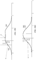
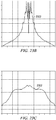
- Figure 3 is a graph 300 illustrating the polarization-preserving performance of a conventional silver screen as a function of viewing angle.
- Graph 300 shows a BRDF measurement of a conventional silver screen using a collimated source (HeNe laser with a 0.633 ⁇ m wavelength), where a P-oriented polarizer is inserted in the illumination path, and either a P- or S-oriented polarizer is used in the detection path.
- P and S are unit vectors parallel and perpendicular to the plane of incidence in the global (substrate) coordinate system, respectively. This should not be confused with the local coordinate system, which is associated with individual reflecting facets embedded in the screen.
- the screen was illuminated at -5° off-normal (corresponding to -10° on the plot), so that the specular direction corresponds to 0°.
- the detector scanned the in-plane angles, where drop-outs occurred due to the finite size of the detection module.
- the PP plot 302 corresponds to the parallel polarizer BRDF, which closely tracks the gain profile.
- the PS plot 304 is the crossed-polarizer BRDF, corresponding to the power converted to S-polarization through the combination of several mechanisms, as a function of scatter angle. This term is relatively "white” in angle space, as would be expected for a diffuse scatter component.
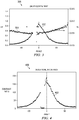
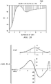
- Figure 4 is a graph 400 illustrating the polarization-preserving contrast performance of a conventional silver screen as a function of viewing angle.
- the polarization contrast ratio (PCR) 402 is plotted as a function of observation angle and is a ratio of the PP BRDF plot 302 to the PS BRDF plot 304 shown in Figure 3 . It will be shown later that this corresponds to a "best case" contrast for linear polarization from a Fresnel standpoint, as the input polarization is contained in the plane of incidence.
- Figure 5 is a graph 500 illustrating the gain curve of a conventional silver screen as a function of viewing angle.
- the gain curve 502 shows the ratio of the PP BRDF to that of a Lambertian scatterer, and as such is independent of polarization. For this screen, the contrast is halved at about 20°. Because the PCR tracks the gain, high gain screens typically show the highest spatial non-uniformity in observed cross-talk.
- Factors that determine the cross-talk leakage term include:
- Engineered surfaces in accordance with the present disclosure may provide more desirable gain profiles using all-reflective dispersion means, which do not exhibit excessive reflectivity in the specular direction. Contributions due to the mechanisms listed above can be severely minimized, if not virtually eliminated.
- control of the slope probability density function allows each observer to have a similar high-contrast experience via improved uniformity in brightness.
- engineered surfaces may allow enhanced image brightness, by directing projection light to seat locations. This further improves color saturation and image contrast by reduction in stray light. Using the processes described herein, screen material can be manufactured with the highest quality at the lowest possible price.
- Factor 1 depolarization due to diffuse scatter from features much smaller than the illuminating wavelength -- refers to depolarization associated with interaction of incident light with surfaces that are approximately on the scale of a few nanometers, to a few hundred nanometers.
- the contribution of this term tends to be virtually white in (projection and observation) angle space and insensitive to polarization basis vector. When observed under a crossed-polarizer microscope, the contribution appears as a background "glow.” This term can be virtually eliminated through the use of high quality optical coatings (low rms roughness) which are substantially free of voids and are conformal to an embossed surface topography which is free of features at this level.
- Factor 2 polarization change due to local anisotropy of binder or additive materials -- is associated with optically thick "transparent" coatings. Such coatings can have anisotropy, which modifies the local state of polarization.
- the teachings of the present disclosure may eliminate this contribution by using single-surface reflection from a mirror-like metal coating. Any additional layers may be low birefringence oxide-like dielectrics which are applied relatively thin, having virtually zero retardation.
- Factor 3 polarization change on (specular) reflection from a single surface -- refers to the geometry of the local reflecting surface and is a result of fundamental differences in the complex reflection of S and P polarizations.
- the associated loss in PCR is relatively insignificant for the typical angles between projection/observation for most cinema environments, but can become significant in more demanding situations. It will be shown that additional conformal dielectric coatings over the metal surface can further reduce this contribution.
- Factor 4 multiple reflections resulting from surfaces that are highly sloped with respect to the illumination direction -- refers to multiple reflections that can occur (and in certain situations are at a maximum) at normal incidence/observation. They are usually associated with highly sloped diffusing structures. That is, a ray that continues in the forward direction after a single reflection, or does not clear adjacent structures after a single reflection, undergoes a secondary reflection. The mean-free path between such events can be much larger than the reflecting feature size, thus leading to other undesirable (image quality) effects. A double-reflected ray can have a highly altered polarization state, thus degrading polarization contrast ratio. Moreover, the impact of such reflections is a function of the polarization basis vector, as will be demonstrated.
- Factor 1 can be virtually eliminated by using continuous micro-reflective structures that contain little or no contribution at the high spatial frequencies associated with diffuse scatter. Theoretically, this can be partially accomplished using some of the design capabilities described by Morris et al. in U.S. Patent No. 7,033,736 (herein incorporated by reference), where arbitrary slope probability density functions can be generated, typical of diffuse scatterers, using all-reflective means. Further, these structures can have pseudo-random distributions in size, location, slope, and height which ensure a matte appearance without compromising performance.
- the engineered structures (diffusers) of the present disclosure should preferably be mass-produced consistently in a manufacturing environment. This may involve roll-to-roll embossing of generating kernels consistent with the specifications described herein. Moreover, subsequent coatings should preferably be applied with a similar high level of quality, for example, by evaporation or sputtering.
- the disclosure describes the use of the diffuser/screens in a cinema environment, it is contemplated that they may be alternatively be used in other environments where visual media is viewed, such as, but not limited to home theatre, gaming systems, virtual reality, flight simulators, etcetera.
- diffuse scatter is often the result of attempts to eliminate hot spots. Because of the tendency for facets to lie parallel to the substrate with statistical surfaces, effort should be made to spoil the reflection in the specular direction. This can be done by increasing diffuse scatter, but it is at the expense of brightness and PCR. According to the present disclosure, the probability density function is engineered in such a way as to be uniform in the vicinity of the specular direction. This allows polarization preservation while at the same time increasing screen brightness.
- the projection lens is (nominally) centered horizontally with respect to the screen, but is typically located above-center vertically. This can range from zero to more than a half-screen offset. It is typical for the screen to have single-axis curvature (about the vertical) with a radius of curvature equal to (optimally) or exceeding the throw distance. This is in fact a requirement for SMPTE compliance when using a screen with gain above 1.3.
- the front section sloped at about 8-10°, and the larger rear section sloped at approximately 20-22°.
- the front section is typically curved (like the screen), while the rear section is typically rectangular.
- the average throw-ratio ratio of throw distance to screen width
- performance may be described for different observation positions from the viewpoint of the hypothetical "ideal viewer.”
- the ideal viewer represents the seat location for which peak brightness of a white frame occurs at the center of the screen (when using a gain screen).
- Other positions of interest include the perimeter seats for which the system should perform satisfactorily. These perimeter seats define the diffusion locus, taken together with the other geometrical considerations discussed above.
- the average vertical offset angle of an axial ray is approximately eight degrees down.
- the vertical offset biases the specular direction downward, which is beneficial for brightness with a gain screen. When designed properly, this places the ideal viewer in a central position of the seating. Conversely, with zero-offset, the optimum viewing location with a gain screen is at the projector, which is clearly not practical.
- a bias in the diffusion angle may be built into the diffuser design, according to the present disclosure.
- Worst-case viewing angles are associated with the perimeter seats (or for a subset of seats for which the system should perform adequately). These seats define the viewing locus. Under ideal circumstance for brightness and contrast, according to the present disclosure, no light is thrown outside of the diffusion locus. Moreover, optimized polarization contrast ratio requires that only single reflections occur within the diffusion locus. In the event that multiple reflections occur, they should preferably occur for reflection conditions outside of the diffusion locus.
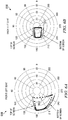
- Figures 6A and 6B are polar graphs 600 and 650 respectively illustrating exemplary polar plots for the viewing locus of a specific auditorium at different viewing positions.
- Figure 6A shows a plot 602 representing the angle of the observation ray (in the global coordinate system), defined by tracing the perimeter of the screen in the front-left seat (e.g., viewing position 132 of Figure 1 ).
- Figure 6B represents the corresponding plot 652 for the rear-left seat (e.g., viewing position 134 of Figure 1 ).
- the latter (652) is contained within the former (602).
- the rear seats define the portion of the locus corresponding to the bottom of the screen.
- Figure 7 is a polar graph 700 showing the viewing locus, similar to those described above in Figures 6A and 6B , for a random sampling of twenty one theatre auditoriums.
- Such data 704 is contained within a perimeter 702, which, for illumination/viewing conditions symmetric about the vertical, defines a diffusion locus that is also symmetric about the vertical. It is a design objective to limit diffusion substantially within the region defined by perimeter 702, to include the viewing locus, which includes substantially all viewing positions plus an arbitrary margin of safety, e.g., five degrees.
- a local coordinate system is defined here by a projection ray vector, and an observation ray vector. This defines a local plane of incidence, which contains the local facet normal vector (where a facet model is typically used for illustration, even though the desired surface may have continuous micro-reflective properties). Because polarization is substantially preserved by the screen, it is reasonable to assume that light deflected by the facet is the result of a specular reflection. The likelihood that a facet exists with the desired orientation is given by the two-dimensional slope probability density function, which is related to the screen gain.
- the local plane of incidence also defines the local S and P vectors (or local eigenvectors), which obey Fresnel equations for reflection.
- the functional coating is typically a metal (e.g ., aluminum), which has a complex refractive index, and therefore is absorptive.
- facet area is large with respect to the illuminating wavelength (or more realistically, that the slope is slowly varying on the scale of a wavelength) it can be considered that light specularly reflects from the surface, preserving polarization.
- SOP state of polarization
- the facet incidence angle should be less than 45°, having ( e.g., a flat screen) infinite throw distance (with a centered projector) and a viewer located at the plane of the screen. More typically in theatre auditoriums, the maximum facet incidence angles associated with the worst case viewer are below 35°.
- Figure 8 is a graph 800 of the Fresnel PCR for circular polarization (or worst-case azimuth of linear polarization) as a function of facet incidence angle.
- the contrast 802 is above 1,000:1 for angles below 25° (which accounts for most of the audience), remaining above 270:1 for angles out to 35°. As such, the Fresnel contribution is relatively small in present cinema environments.
- 7,110,175 discloses the deposition of an aluminum layer to address the reflectivity difference by using a dielectric layer to make the reflectivity of S- and P- the same.
- Lippy fails to recognize that contrast is impacted far more by phase difference than the reflectivity difference.
- the natural objective for contrast is to minimize the local incidence angles, and thus to have higher gain.
- the dominant depolarization mechanism is multiple scattering events, which Lippey does not even mention. In other words, Lippey does not recognize the dominant mechanism that contributes to contrast performance or the techniques for such optimization of contrast performance.
- the second objective identified by Lippey is to match the amplitude reflectivity of S and P polarizations.
- polarization preservation is likely more important than increasing efficiency.
- reducing the phase difference between S and P components through thin-film compensation helps preserve polarization.
- a dielectric film of arbitrary thickness and index, with the performance metric being the PCR at 589 nm (where the input polarization is at 45° to the plane of incidence) produces the best results when the refractive index is minimized (e.g ., with MgF 2 ).
- the PCR at a facet incidence angle of 35° is 139:1 (which is lower than bare aluminum).
- Adding a 0.34 wave thickness layer of MgF 2 yields a contrast of 23,915:1.
- the contrast is lower for the compensated case (1,934:1), but still, the contrast remains significantly higher than the uncompensated case (360:1).
- contrast generally increases, but the compensated case remains at least a factor of three larger than the uncompensated case.
- a tilted facet has linear eigenpolarizations
- performance of a system based on linear polarization is azimuth dependent. If the input polarization is contained in the facet plane of incidence, then polarization is preserved on reflection. If this mechanism is important in determining contrast, then eyewear can be selected to optimize overall performance. For instance, screen corners tend to correspond to the largest facet incidence angles, which may tend to be closer to the ⁇ 45° azimuth angle than the 0/90° azimuth. In these circumstances, a system based on ⁇ 45° linear polarization eyewear may be used. As for systems using a circular basis, there is no relief from polarization change on reflection for any azimuth because, in fact, the contrast is independent of azimuth angle. In the event that contrast is dominated by multiple reflections, then the above argument may not be a relevant design consideration.
- the coated samples verified that contrast was several hundred to one when the input polarization was parallel to the structure axis, but was substantially lower when the sample was rotated, with contrasts of only tens to one in the 45° azimuth. Note that these measurements were made in a retroreflecting arrangement.
- Statistical surfaces such as metal-flake screens, are also prone to double-reflections. Often, the mean-free path between pairs of facets is substantially larger than the actual reflecting feature sizes.
- the brightness of facet pairs can be observed to change in unison. This is likely due to polarization-converted light emerging from opposing propagation directions. Along the eigendirections, the pairs are highly extinguished. Due to the high degree of polarization conversion with retroreflection, the pairs become very bright in the ⁇ 45° azimuth.
- the effective geometry of the pairs is often very similar (dictated by the overlap area of the facets), which is another factor that makes them easily identifiable.
- Retroreflecting arrangements have potential benefits from a brightness standpoint. That is, if the direction of peak diffusion is, in general, counter to the incident direction, then light from the projector will have a greater tendency to be thrown toward the audience. Beaded screens, for example, can have the benefit of functioning like a cat's-eye retroreflector. Because they have a self-correction property, retroreflectors can virtually eliminate the need for local control of diffusion properties as a means of optimally dispersing the light. However, care should be taken to ensure that such retroreflections do not compromise polarization, as would occur with certain (e.g ., corner-cube) retroreflectors. In the case of double reflections from facet-pairs, polarization is substantially converted to the orthogonal state.
- lenticular-like periodic structures have been used on cinema screens to disperse more in the horizontal direction relative to the vertical.
- structured surfaces are used to disperse light to a greater degree in the horizontal than the vertical, which are prone to secondary reflections
- a system based on 0/90° polarization eyewear may be used. More likely, however, screen structures that are prone to secondary reflections will not perform adequately.
- the Fresnel contribution is zero in the retroreflecting direction (for single reflections), becoming significant as the facet incidence angle approaches 20°, and growing as angle increases. It is clearly polarization dependent, vanishing when the input is parallel/perpendicular to the facet plane of incidence, and maximum at ⁇ 45°.
- the contribution to PCR is independent of azimuth when using circular polarization. Thus, if linear PCR results are a strong function of azimuth (or if there is a significant difference between linear and circular PCR) at large incidence angles, then the Fresnel term may be important. This assumes that the contribution from multiple reflections becomes relatively insignificant at such large angles (or is separable).
- Figure 9 is a graph showing that the contrast of the linear case 902 is over 160:1, where the circular case 904 is only 110:1. Because this difference is observed along the retroreflecting direction, any difference in PCR may be attributed to multiple reflections, unless the PCR of the circular case is inherently lower. To obtain these results, a 532 nm laser was directed through a pair of orthogonal linear and circular polarizers to test the baseline performance at normal incidence. The baseline PCR was measured to be 888:1 for the linear case and 895:1 for the circular case, the difference of which is well within experimental error and limited by the polarizer. Thus, substantially higher PCR may be provided by the engineered surface of the present disclosure through the elimination of double reflections.
- Another objectionable aspect of statistical surfaces is the lack of spatial control of BRDF characteristics. Spatial variation in the facet probability density function can produce a non-uniform appearance. The feature size associated with such variations may be highly dependent upon the manufacturing processes and the statistical control aspects of each. Given that the size of a pixel on an average screen for a full-HD (1024x2048 pixel) 2k projector is roughly 7mm, significant variation in reflected intensity over this (or larger) sizes is likely problematic. To demonstrate this, a screen sample was illuminated normally at a distance of 305mm, with an amplitude stable 532nm laser. The laser and detection module were mounted with a separation of 45mm on the same rail carrier (in-plane), and were translated in 1mm increments along the screen axis. The detector aperture is 5mm, virtually eliminating the contribution of speckle. Some smoothing of the profile is assumed to occur as a consequence of averaging over the associated detection solid angle.
- the total scan range in a particular position was 100mm, with no significant difference in results for other positions on the screen.
- Screen samples from two vendors were tested.
- the standard deviation in reflected power was 6.8% and 5.2% respectively.
- the maximum deviation was +21% and -16% for Sample A, and +11% and -14% for Sample B.
- the illumination light can exhibit spatial coherence over areas that are significant relative to the screen resolution area. This can exacerbate screen appearance uniformity problems via coherent superposition on the retina.
- the engineered microstructrure can have a spatial frequency noise structure superimposed on the desired topography. Such a structure does not impact the single-reflection requirement, but randomizes the phase in such a way that light collected by the eye contains a substantially uniform representation in phase space. If the amplitude of the noise is some multiple of a wavelength and the wavelength is similar to the spatial coherence length of the light, then the phase randomization should be sufficient to substantially reduce speckle.
- the eye resolves approximately one arc minute below which the perceived intensity can be considered a weighted integration of the probability density that generating kernels scatter from the illumination direction into the observation direction over the associated area. This probability is related to the local slope probability density.
- the integrated probability varies spatially, meaning that the sampled area does not conform to ensemble statistics, the screen will have a grainy texture, which is objectionable. This can happen both as a consequence of large feature sizes, as well as their specific distribution over the screen surface. Often, the relative intensity fluctuations increase with observation angle, where the probability that the required slope area exists is substantially diminished relative to the specular direction.
- the engineered diffuser is analyzed and modified spatially to create more uniform intensity distribution after single reflections. This substantially reduces the graininess of the appearance while preserving the polarization. To a large extent, this is accomplished by the engineered diffuser shape in accordance with the present disclosure. Locally, each scattering feature fills the entire viewing locus ergodically. Spatial fluctuations are due mainly to randomization and tiling effects. The percentage of area subject to such effects can be small relative to the unaffected region, i.e., it can be limited to regions where the engineered generating kernels are overlapping. By using generating kernels with zero slope and zero height at the boundary, this effect is substantially limited to the specular region of the gain profile where it is much less objectionable.
- the screen contains a statistically homogeneous distribution of generating kernels, it is necessary that such kernels substantially satisfy the extreme conditions of illumination and observation.
- Every point on the screen accepts illumination from one (or more) discrete angles. Over the areas associated with ensemble statistics, this illumination can typically be considered collimated.
- light should be scattered into a range of angles associated with the diffusion locus, subject to gain requirements. For each such point, an important quantity is the extreme angle formed between the specular direction and the observation direction.
- the perimeter termed here as the "diffusion locus" defines the screen microstructure diffusion requirements.
- the diffusion locus is related to the slope probability density of the screen microstructure.
- this structure is referred to herein as the generating kernel, and for a surface diffuser it will have some topographical shape that determines the diffusion profile of light reflected off of it.
- this generating kernel carries the entire ensemble statistics of the required diffuser so that point-to-point variation in the diffusion are minimized at the smallest possible scale.
- the generating kernel may not fully satisfy these statistics, but an ensemble of such structures may.
- An aspect of the present disclosure is to design the profile of a generating kernel (or microstructure comprising a plurality of generating kernels) to eliminate secondary reflections within the facet incidence angles associated with the full range of illumination/observation angles.
- this is accomplished by determining the diffusion locus of illumination/observation to provide light to all required seats in the auditorium (based on the geometrical considerations discussed previously) and designing a generating kernel (or microstructure comprising a plurality of generating kernels) that achieves at least one of the following: (1) a slope probability density function that is uniform throughout the diffusion locus (virtually Lambertian), with little, if not no, "spike” in the specular direction; (2) a slope probability density function that is uniform spatially ( e.g ., ⁇ 1%) so that there is little, if not no, perceived modulation in brightness; (3) a slope probability density function that has a sharp cutoff in angle space at the perimeter of the diffusion locus; (4) a generating kernel layout that is free of features smaller than
- Figure 10 is a graph 1000 of a one-dimensional example of a concave structure 1002 which has a uniform probability density function with a hard cutoff at 80°.
- Figure 11 is a diagram illustrating a 1D structure 1100 which is both periodic and satisfies the same criteria.
- the convex elements 1102 in the structure are obtained by rotating the concave elements by 180°.
- Adjacent cells in the structure may have arbitrary size as long as the aspect ratio is preserved, the size remains small enough to be visibly irresolvable but large enough to prevent diffuse scatter ( e.g. less than several hundred microns and greater than a couple of microns), and no multiple reflections occur within the diffusion locus.
- Light incident at angles up to 10° suffer no multiple reflections as shown by reflected ray 1104, which clears the adjacent peak.
- a randomized surface may be generated by tiling multiple unit cells with different widths as shown in 1106.
- Reflecting structures may have different shapes as long as the density of surface elements with slope ⁇ is equal to ( ⁇ ). In particular, this allows the design to accommodate different scattering requirements in different regions of the screen.
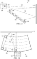
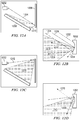
- Figures 12A-12D are schematic diagrams showing a side view of an arbitrary theater including the projector, screen, and seating area.
- ray 1204 travels from the projector 1202 to the bottom part of the screen 1206. In order to illuminate the seating area 1208, it should be scattered into the diffusion locus 1210.
- the diffusion locus is defined in accordance with the angular extremes in illumination and detection/observation. Within the diffusion locus, substantially only single reflections occur from the screen toward the diffusion locus; whereas outside the diffusion locus, multiple reflections may occur.
- Figure 12B is a schematic diagram showing an example microstructure 1222 at the screen surface in Figure 12A .
- Rays 1224, 1226, and 1232 are all approximately parallel to ray 1204 but illuminate different parts of the microstructure.
- Rays 1224 and 1226 experience single specular reflections 1230 and 1228 before entering the diffusion locus 1210.
- Ray 1232 experiences two specular reflections but the exiting ray 1234 does not enter the diffusion locus 1210 and so will not likely cause a decrease in PCR.
- Figure 12C shows a ray traveling up from the projector to the top of the screen 1206 which illuminates a substantially different viewing location within the diffusion locus.
- Figure 12D illustrates reflections 1268 from a microstructure 1262 located at the top of screen 1206 showing that no rays incident on the top part of the screen experience multiple reflections although some reflected rays 1270 do not enter the diffusion locus 1240.
- rays traveling down from the projector 1202 and impinging on the bottom part of the screen 1206 should preferably scatter into a substantially different portion of the diffusion locus in order to illuminate the seating area, i.e., the slope probability density is also a function of incident angle.
- the slope probability density is also a function of incident angle.
- some double reflections may be tolerated as long as they result in light that does not enter the diffusion locus.
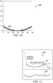
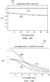
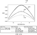
- Figures 13A and 13B are graphs 1300, 1350 of several possible "gain" curves for engineered screens in which light is only scattered into the diffusion locus shown in Figure 7 .
- the gain is calculated within the diffusion locus and is assumed to be symmetric about the vertical axis, but with a sharp cutoff, as shown in Figure 7 .
- Graph 1300 illustrates that a uniform (Lambertian-like) profile 1310 within the diffusion locus would result in an efficiency increase of almost 30% over a typical matte white screen profile 1320.
- Graph 1350 illustrates that if the gain profile has the same functional shape as the existing gain silver screen, the increase in efficiency 1360 is almost 100%.
- the gain curve can be flattened, shown by line 1340, such that the overall uniformity is better than the conventional silver screen, shown by line 1330, i.e., widen the gain profile of the current silver screen, with substantially the same maximum brightness.
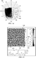
- Figure 14 is a polar plot 1400 of the facet-normal locus, relative to the screen surface normal, that substantially illuminates the entire viewing region with light from the projector.
- facet normals 1410 that direct light from the projector to each individual seat.
- the union of all such sets across the surface of the screen defines the locus of facet normals 1420 to ensure that each viewer receives light from substantially all parts of the screen. Any facet normals falling outside this locus result in wasted light.
- the black dots 1410 are computed from the left side extreme-viewing-location seats from a random selection of theaters.
- the locus or curve 1420 is extended to encompass the viewing angles for the right-most seats as well.
- the desired geometrical properties for a polarization preserving projection screen have been identified as: (1) Filling the diffusion locus with uniform light intensity; (2) Preventing multiple reflections of light by (a) introducing a cutoff angle in the light distribution to prevent reflected light from hitting the screen a second time and (b) keeping features with steep slopes well separated so that scattered light at large angles does not encounter a second surface; (3) Achieve ergodicity within a region smaller than a pixel.
- the full diffusion locus should be sampled uniformly by an area of the screen that is smaller than a pixel so that the screen intensity is spatially uniform; (4) Ensure that all features are significantly larger than an optical wavelength to prevent scatter; and (5) Avoid periodic structures that could combine with the pixilation of the projector to produce moiré, or interference between sets of fine pattern grids. A curve was found that satisfied these requirements for 1D scattering.
- ergodicity is the condition wherein the average value of some parameter over a finite region has converged to the ensemble average of the entire region. When a region of a certain size is said to be ergodic, it is not statistically different from any like-sized or larger region in the ensemble.
- the first is to determine a set of rules that can be used for random (stochastic) processes that on average satisfies the requirements. Identifying fully random processes that will in general satisfy all of the design requirements may be complicated, but the manufacturing of these surfaces may, in general, be easier.
- the second strategy is to design a custom structure that explicitly satisfies all of the above requirements. This ensures the best performance, but requires a manufacturing technique that can transfer this design to the screen surface with high fidelity.
- a holographic diffuser will be composed of 2D Gaussian peaks whereas a metal flake paint will be composed of a collection of planar facets with sharp edges. Neglecting any sharp edges, the limit of a large number of such features is expected to conform to Gaussian statistics. Therefore, a stochastic diffuser may be approximated as a randomly distributed collection of Gaussian scattering features wherein the features have some characteristic height d , and width ⁇ .
- the mean values of d and ⁇ can often be independently controlled.
- ⁇ is the characteristic speckle size and can be adjusted by modifying the distance to the aperture or the size of the aperture. If the speckle pattern is recorded in photo-resist, then d can be controlled by modifying the exposure time and/or the developing conditions.
- ⁇ will be related to the size of the ablating particles and d will be proportional to their incoming velocity (to first-order). Therefore, constructing design rules for the generation of stochastic diffusers depends on an understanding of the relationship between d , ⁇ , and the preservation of polarization, i.e., double reflections.
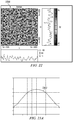
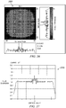
- Figure 15 is a schematic diagram illustrating a top-down view 1500 of an exemplary Gaussian surface and respective side views 1502 and 1504 that have been simulated with Gaussian statistics to verify the computational model against experiments on physical samples.
- a 2D diffuser with Gaussian statistics is simulated by populating a plane with randomly positioned Gaussians (e.g ., Gaussians 1506 and 1508). To first order, it is sufficient to use identical Gaussians ( ⁇ , d are constants). Relatively uniform coverage is provided by locating the peaks on a hexagonal lattice and then randomly translating their positions by a Gaussian weighted distance.
- the scattering distribution and gain of this structure 1500 was simulated using non-sequential ray tracing (ASAP) software.
- the illumination was a uniform collimated light source that fully sampled the surface at normal incidence.
- the polarization of individual rays was neglected and non-geometrical effects were ignored (e.g ., Fresnel reflectivity, scattering from sub-wavelength features).
- To compute the gain all of the rays that reflected from the surface only once were collected.
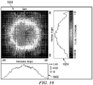
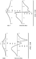
- Figure 16 provides a graph 1600 illustrating the density of the rays reflected from the exemplary Gaussian surface of Figure 15 , plotted as a function of angle.
- Graph 1600 depicts this 2D ray trace as a Gaussian noise surface and graphs 1602 and 1604 illustrate the profile from horizontal and vertical aspects respectively.
- the simulated rays have only reflected from the surface once and the intensity has been scaled by cos( ⁇ ) to show the gain.
- a gain plot of all of the rays that reflected from the surface twice can be used to compute the depolarization effect of multiple reflections.
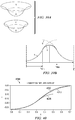
- Figure 17 provides a graph 1700 illustrating an intensity plot of rays that experienced a double reflection from the exemplary Gaussian surface of Figure 15 .
- Graph 1700 and side views 1702, 1704 reveal that the Gaussian surface is not fully ergodic, i.e., because the scattered distribution is not radially uniform this surface is not statistically smooth. This is consistent with experiments on holographic diffusers with similar feature sizes in which significant intensity variation is seen between adjacent 3 mm x 3 mm patches. However, a radial average of the distribution is a good approximation of the full distribution.
- the polarization contrast ratio due to multiple reflections is the ratio of the intensity due to single reflections, as shown in Figure 16 , to the intensity due to double reflections, as shown in Figure 17 .
- Figure 18 is a graph 1800 illustrating contrast against gain for a series of simulations with different amplitudes for Gaussian diffuser surfaces.
- the line 1802 showing the simulated result has consistently higher contrast than the line 1804 showing the experimental result due to the lack of point scattering, Fresnel effects, and finite polarization sensitivity of the measurement system.
- This series of experiments highlights some of the limitations of a statistical surface as a diffuser for a cinema screen. There is an intrinsic tradeoff in such structures between gain (and thus, illumination uniformity) and contrast. To the extent that high gain can be tolerated, higher contrast can be obtained. However, it should be noted that to achieve both high contrast and low gain requires a carefully engineered surface.
- the scattering properties of a random surface may be calculated.
- z r de ⁇ r 2 ⁇ 2
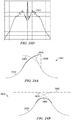
- Figures 19A-19D provide schematic diagrams showing plots of reflection conditions for different spacings between Gaussian peaks.
- Figure 19A is a schematic diagram showing a reflection of a ray 1904 off a single scattering feature 1902. For a single scattering feature, as long as ⁇ c is less than 90°, the reflected ray 1906 will be directed away from the surface and there will be no secondary reflection.
- Figure 19B is a schematic diagram showing the reflective properties as adjacent features 1922 and 1924 get closer. However, as adjacent features 1922 and 1924 approach, there is some region in which for large reflection angles, a second reflection does occur.
- Figure 19C is a schematic diagram showing the situation as the peaks 1932 and 1934 approach even more.
- Figure 19D is a schematic diagram showing the scenario of the two peaks 1942 and 1944 overlapping, such that the maximum slope is increased, which in many cases leads to a multiple reflection. Therefore, for adjacent Gaussian peaks, there exists a locus of regions in which multiple reflections occur.
- Figure 20 is a graph 2000 illustrating that for two Gaussian peaks with equal height and cutoff angle ⁇ c , there is a computed locus of separations in which no multiple reflections occur.
- ⁇ c of the Gaussian is preferably less than 52°.
- ⁇ c less than 80°, no multiple reflections occur between the peaks, but this may occur as the peaks begin to overlap. Should the possibility of three peaks overlapping be considered, then ⁇ c would be smaller still. Unfortunately, ⁇ c is considerably smaller than the desired diffusion locus for a typical theater.
- the reflected angle as a function of position is calculated for different peak-to-peak separations.
- the peaks are well-separated (see, e.g. Figure 21A )
- Figure 21B shows the smaller peak is located approximately on the shoulder of the larger peak.
- the maximum slope then decreases as the peaks exactly overlap (see, e.g., Figure 21C ).
- the overall effect is similar to the superposition of equal sized features with one important difference: the same maximum slope condition is obtained but the average depth of the surface has not significantly increased. Consequently the large-angle scatters remain relatively well separated and the likelihood of a second reflection is smaller.
- Figure 22 is a graph of a simulated noise pattern 2200 illustrating two patterns composed of structures with different height and width but substantially identical cutoff angle.
- Figures 23A to 23D are graphs showing a comparison of the gains and contrasts of both a diffuser composed of two patterns and different characteristic sizes versus a diffuser composed of one pattern and without different characteristic sizes.
- the gain calculated from the diffuser with different characteristic sizes yields a much smoother curve 2302 (see Figure 23A ) than the gain curve 2352 calculated from only a single periodic structure (see Figure 23C ). This is because the smaller feature size of the first structure allows the curve 2302 to become nearly ergodic in a smaller area, but the gain of the two structures is approximately the same.
- the peak contrast of the two-pattern diffuser is substantially five times larger than the peak contrast of the single pattern diffuser (see Figure 23D , showing an enlarged portion of Figure 23B ).
- the average contrast is more than twice as large.
- a practical technique of increasing the maximum contrast in a purely statistical structure is to superpose two patterns with different periodicities.
- the practical limitations of this technique are that the smaller feature should preferably remain large relative to the wavelength of light (e.g., in the order of 10's of ⁇ m) and the larger feature should preferably remain small relative to a pixel ( e.g., in the order of 100's of ⁇ m).
- this can be accomplished by performing two exposures in which the second exposure is adjusted to have approximately 1/5 of the height and 5 times the frequency.
- Another technique to accomplish this would be to apply a high gain metal flake paint to an embossed substrate.
- This function can be generic, such as a Gaussian, in which case the statistics should preferably be constrained in an essentially non-Gaussian way in order to satisfy the design constraints.
- the function may be a generating kernel that locally satisfies the desired property of ergodicity.
- any 2D curved surface can be represented by a 2D array of values representing the height of the surface.
- the pixel values in Figure 22 represent the height of the surface at each point.
- substitution and addition Two straightforward and computationally inexpensive methods to fill such an array with multiple copies of the generating function are substitution and addition.
- Substitution consists of replacing the pixel values within a section of the final array with the pixel values of the generating function. In regions where two generating functions might overlap, one of them may be truncated.
- Figure 24A is a graph 2400 illustrating truncated overlapping functions 2410 and 2420.
- Overlapping results in a vertical facet 2430 that must be corrected to prevent sources of multiple scattering. This can be accomplished by replacing the vertical facet with a sloped facet 2440 that directs light out of the diffusion locus, i.e., with slope larger than ⁇ c but still sufficiently small enough to prevent a second reflection.
- Addition consists of adding the pixel values of the generating function to the pixel values of the total array.
- the height and slope of the generating function should approach zero at the boundary 2480.
- the advantage of this technique is that there are no facets at the boundaries and so it is in principle possible to make better use of the available light.
- addition leads to a decrease in the average aspect ratio and thus an increase in the gain of the diffuser and thus must be corrected for as discussed below.
- ⁇ is known as a function of r
- Figure 25C is a graph 2550 of an exemplary generating kernel solution generated by combining solutions 2500 and 2510. Following this procedure, arbitrary diffusion profiles, ( ⁇ ), are possible, subject to the aforementioned limitations on cutoff angle.
- Figure 26 is a graph 2600 illustrating the gain simulated via non-sequential ray tracing for a 2D Lambertian generating kernel.
- Figure 27 is a graph 2700 of the radially-averaged gain for the generating kernel of Figure 26 .
- Completely filling a screen with a solution 2550 presents the problems of substantially eliminating empty space, but with minimal distortion to the generating kernel.
- One way to fill a screen with the engineered generating kernels is to tile the generating kernels in a lattice configuration, e.g ., a square, hexagonal, or any other regular shape lattice.
- Figure 28 is a schematic diagram illustrating an exemplary hexagonal lattice 2800 configuration.
- empty space is undesirable in order to optimally use the available light and to prevent an increase in the specular reflectivity ("spike" in the reflectivity).
- generating kernels 2802 in a hexagonal lattice 2800 may undergo overlapping. For example, to eliminate empty space on a screen using a hexagonal lattice 2800 of generating kernels with a unit cell diameter of 2/ ⁇ 3, approximately 20.9% of the unit cell areas would be overlapping.
- Figure 29 is a schematic diagram illustrating the unit cell overlap 2910 of a hexagonal lattice 2900 of generating kernels.
- Figure 30 is a diagram illustrating the unit cell overlap 3010 of a square lattice 3000.
- a square lattice 3000 may require an additional smaller unit cell 3020 to fill space, with the smaller unit cell's radius a function of the large cell's 3030 radius.
- a 17.9% overlap is optimum.
- overlap of the generating kernels modifies the gain of the combined structure.
- the change in gain is a function of the center to center distance of the nearest-neighbor individual generating kernel which, in turn, is a function of the azimuth within the lattice. Therefore, a perfect lattice has a deviation in the scattered distribution reflecting the local arrangement of generating kernels.
- a hexagonal lattice has six-fold symmetry in which the nearest neighbors of a given point are distributed around that point every 60°. Consequently, the scattered distribution will have an azimuthal modulation with a periodicity of 60° whose amplitude is proportional to the amount of overlap of the generating kernels.
- Regular lattices of generating kernels may lead to moiré, diffraction, and other undesirable effects. Modifying the regular lattice to achieve more randomization, for example, by using a hexagonal lattice with randomized lattice points, reduces these effects. Additional overlap may result from randomizing a regular lattice. Also, the sizes of the unit cells may be randomized in addition to their positions. However, in this case it becomes nearly impossible to pre-correct for overlap of the structures.
- Figure 31 is a schematic diagram of a hexagonal lattice 3100 allowing 0.1l of randomization of the center point. This configuration yields an overlap area 3110 of 60%.
- Figure 32 is a diagram 3200 of a hexagonal lattice with smaller cells 3220 dispersed in between the larger cells 3230, resulting in a much smaller overlap area 3210 of 9.4%.
- the cell arrangement in Figure 32 allows for more randomization.
- the hexagonal lattice has a six-fold rotational symmetry but if elements of two separate hexagonal lattices are combined with a 30° rotation between them, then the symmetry is increased to 12-fold. This can be accomplished by any number of infinite sets of semi- and demi-regular tessellations.
- FIG 33A is a schematic diagram 3300 illustrating a semi-regular tessellation pattern.
- Figure 33B is a schematic diagram 3350 illustrating the unit cell of this tiling, which consists of two hexagonal lattice components 3360 and 3370 as well as three square lattices 3380. The vertices of the polygons indicate the centers of generating functions.
- Figures 33C and 33D are schematic diagrams illustrating vertices of the polygons 3390 and 3396 (and centers of the generating functions). The repeat distance of the structure is still significantly smaller than a pixel.
- Arbitrarily large pseudo-random tilings can be generated by performing a 2D monte-carlo simulation of crystal melting. Such methods are well known for the study of interactions of hard disks as well as particles with arbitrary attractive/repulsive interaction potentials.
- the starting point of the simulation is to generate a 2D lattice of particles on a regular grid.
- a random particle is then picked from the ensemble and translated by a small fixed amount. If the translation results in a region that is not covered by any disk, then the move is rejected. If the translation results in a decrease in the total amount of overlap of the particles then it is accepted. If the total amount of overlap increases, then the move is accepted with a probability that is inversely proportional to the amount of increase. This process is repeated until the system reaches equilibrium.
- Figure 34 is a schematic diagram 3400 of randomization via horizontal displacement. Uniformly generated displacements may ensure that the surface is fully covered, as shown in 3400.
- Figure 35 is a graph 3500 of the probability distribution for cell center to cell center displacement for a surface with randomized horizontal displacement as shown in Figure 34 .
- the maximum displacement for adjacent structures is 2.0 and the mean displacement is 0.905.
- a generic structure for example, a Gaussian peak, does not necessarily produce the ideal scattering distribution. Instead, the statistics of the size and position of the structure may be controlled such that the distribution is achieved by some relatively large number of features.
- a generic feature such as a Gaussian peak is useful for determining design parameters.
- One cell, generating kernel, or microstructure comprising a plurality of generating kernels, would ideally have a slope approaching zero at a certain cut off radius, in order to allow cells to be stitched together seamlessly.
- An ideal generating kernel, an engineered generating kernel, or microstructure comprising a plurality of generating kernels, would also preferably be ergodic, in that the generating kernel individually produces the entire desired distribution function.
- a generating kernel that produces a Lambertian distribution is locally ergodic.
- An ergodic generating function helps ensure that intensity variations over the surface of the diffuser are minimized.
- ⁇ max 2 tan ⁇ 1 2 z 0 e ⁇ 1 / 2
- adjacent peaks may cause double reflections depending on ⁇ C and proximity, but for ⁇ C less than ⁇ 80°, there are no multiple reflections (except for peaks which overlap), as shown in Figure 20 .
- Figure 36 is a graph 3600 of diffusion angle as a function of separation of Gaussian peaks.
- Figure 37 is a graph 3700 illustrating the cutoff angle of a structure with overlapping Gaussian features.
- overlapping unit cells and randomizing the location of unit cells may result in similar problems disclosed above, for example, double reflections and changing of the gain profile.
- the chance of double reflections is substantially eliminated, leaving the change in gain profile to correct.
- Figures 38A and 38B are graphs 3800 and 3850 illustrating engineered Lambertian diffuser overlap in two sample configurations.
- Lines 3810, 3811, and 3812 represent Lambertian surfaces.
- Line 3820 represents the sum of the lines 3811 and 3812, indicating that the gain of the sum-surface is too high in configuration 3800.
- line 3820 is pushed even further down, indicating that the gain is even higher.
- Figures 39A and 39B illustrate one method of pre-correcting the generating kernels to address overlap.
- Generating kernel A, generated by revolving line a, is ergodic;
- generating kernel B, generated by revolving line b, is ergodic;
- Figure 40 is a graph 4000 of the pre-corrected cell with Lambertian diffuser overlap.
- Lines 4010 and 4020 represent the target diffuser shape.
- Line 4030 is the solution that produces line 4020 while minimizing deviation from line 4010.
- the slope is zero at the edges of the generating kernel.
- the gain profile has a sharp cutoff at 80°, which results in substantially no diffusion beyond 80°.
- Figure 41A is a graph 4100 of an example gain profile 4110 showing separately the contributions from the overlapping regions 4120 and non-overlapping regions 4130 after the structure has been randomized. To the extent that the pre-correction of the overlap region is imperfect, the total gain does not track the target gain as shown by the lines 4110. The non-overlap regions may also be pre-corrected to account for the error.
- Figure 41B shows a graph of an example gain profile in which the overlapping and non-overlapping regions have complementary corrections such that the total gain is equal to the target gain.
- G ⁇ G a ⁇ A a + G b ⁇ A b
- G( ⁇ ) is the target gain
- G a ( ⁇ )/G b ( ⁇ ) are the gain curves associated with non-overlapping and overlapping regions of the generating kernel
- a a /A b are the areas of non-overlapping and overlapping regions respectively.
- this is a deterministic procedure that reaches the optimum design in a fixed number of steps, i . e . design of generating kernel in overlap region, pre-correction of generating kernel in overlap region, and design of generating kernel in non-overlap region.
- each individual generating kernel maps substantially the entire diffusion profile, large-scale spatial fluctuations due to statistical variation are largely avoided, even for large scattering angles, i.e., each individual generating kernel has at least two regions contributing to the intensity at any given azimuthal angle.
- Randomizing the height of the surface of the diffuser by adding some form of noise can be used to address the problem of coherent speckle near the retro-reflection direction.
- the amplitude of this randomization should be some small multiple of an optical wavelength in order to scramble the phase of the reflected light.
- the cost of screen material can be minimized by leveraging existing roll-to-roll processes as much as possible.
- the infrastructure to manufacture roll-stock of optimized screen material may include apparatus that performs micro-embossing, metallization, transparent dielectric (hard-coat) coatings, precision slitting and perforation (for acoustic transmission).
- roll-to-roll embossing processes that are free of (transverse-direction) down-web seams associated with conventional nickel shims.
- UV embossing with a seamless embossing drum produces continuous diffuser material.
- diffuser roll stock is easily converted to finished screens by joining such strips.
- a back-end film joining process may be used to manufacture finished cinema screens. This process should preferably provide sufficient joint strength and reliability when the screen is mounted or stretched on the frame. The seam (and any surrounded area impacted by the joining process) should preferably be sufficiently small that it is not observable to the audience.
- a potential benefit of film joining prior to coating is that optically thick layers can planarize small features.
- joins in such screens are frequently observable because there is an asymmetric "step" in the seam.
- the associated macroscopic facet creates a large disruption in the angular dispersion of light.
- seams are generally not observable when the gap is below approximately 50 microns, and in most instances, up to 100 microns. This can probably be even larger when further steps are done to mask the join, such as randomizing the edge profile.
- the two sheets can be butted together, either by driving the sheets together locally with a system of rollers of suitable profile, or by translating a sheet using a vacuum table to globally butt the materials together.
- the films can be joined together using any one of several methods, including adhesives, chemicals, or welding processes.
- Adhesives can include UV cures, e-beam cure, or various thermo-set processes.
- Chemical bonding can include solvents, or doped solvents. Welding processes can include various means of delivering thermal energy to the join, preferably lasers.
- backer-strip which creates a T-joint.
- the thickness and size of the backer strip can be selected to ensure that the front surface of the finished (stretched) screen is uniform across the boundary.
- a secondary backer sheet such as a fabric, which further improves the strength and appearance.
- a more sophisticated screen design according to the present disclosure may involve local (position specific) control of diffusion properties. This can be done by manufacturing rolls of material that are dedicated to specific locations on the screen. Typically, this involves a bias angle in the diffusion direction, or in the case of a Lambertian-like screen, a (first-order) bias in the location of the centroid of the locus.
- the local correction is likely to be in the horizontal direction.
- the design of the cross-web diffusion profile of any sheet can vary adiabatically, such that there is no abrupt change in diffusion profile at the boundary between sheets. This allows very large screens with quasi-continuously varying optimized diffusion properties in the horizontal direction.
- a screen manufactured as described above could have the same performance as a screen curved about the vertical, but in a flat format. Moreover, the effective performance of a compound-curved (e.g., toroidal) screen could be achieved by curving the aforementioned screen about the horizontal axis. This eliminates the complications of manufacturing a large compound curved screen (e.g., pulling vacuum on the volume behind flat/flexible screen material).
- a compound-curved (e.g., toroidal) screen could be achieved by curving the aforementioned screen about the horizontal axis. This eliminates the complications of manufacturing a large compound curved screen (e.g., pulling vacuum on the volume behind flat/flexible screen material).
Landscapes
- Physics & Mathematics (AREA)
- General Physics & Mathematics (AREA)
- Engineering & Computer Science (AREA)
- General Engineering & Computer Science (AREA)
- Optics & Photonics (AREA)
- Mechanical Engineering (AREA)
- Overhead Projectors And Projection Screens (AREA)
- Projection Apparatus (AREA)
- Optical Elements Other Than Lenses (AREA)
- Transforming Electric Information Into Light Information (AREA)
- Testing, Inspecting, Measuring Of Stereoscopic Televisions And Televisions (AREA)
Claims (4)
- Microstructure réfléchissante profilée destinée à un écran de projection (110) comprenant :un substrat (2800), etune série de grains générateurs (2802) répartis sur au moins une surface du substrat, chacun des grains générateurs de la série de grains générateurs ayant une forme topographique permettant d'éliminer essentiellement les réflexions secondaires de la lumière dans une plage d'angles d'incidence prédéfinie, etau moins deux des grains générateurs se chevauchant, et au moins l'un des grains générateurs qui se chevauchent étant disposé pour effectuer une correction préalable d'un décalage résultant d'un chevauchement de grains générateurs adjacents.
- Microstructure réfléchissante profilée conforme à la revendication 1,
dans laquelle un sous-ensemble de la série de grains générateurs satisfait à un modèle statistique prédéfini de sorte que la variation point à point de la réflexion soit essentiellement minimisée. - Microstructure réfléchissante profilée conforme à la revendication 1 ou 2,
dans laquelle les grains générateurs de la série de noyaux générateurs sont répartis selon un treillis essentiellement régulier ou selon un motif de mosaïque. - Microstructure réfléchissante profilée conforme à la revendication 1, qui est essentiellement ergodique.
Applications Claiming Priority (3)
| Application Number | Priority Date | Filing Date | Title |
|---|---|---|---|
| US2413808P | 2008-01-28 | 2008-01-28 | |
| EP09705162.7A EP2240825B1 (fr) | 2008-01-28 | 2009-01-28 | Écran de projection préservant la polarisation |
| PCT/US2009/032307 WO2009097371A1 (fr) | 2008-01-28 | 2009-01-28 | Écran de projection préservant la polarisation |
Related Parent Applications (2)
| Application Number | Title | Priority Date | Filing Date |
|---|---|---|---|
| EP09705162.7A Division-Into EP2240825B1 (fr) | 2008-01-28 | 2009-01-28 | Écran de projection préservant la polarisation |
| EP09705162.7A Division EP2240825B1 (fr) | 2008-01-28 | 2009-01-28 | Écran de projection préservant la polarisation |
Publications (2)
| Publication Number | Publication Date |
|---|---|
| EP3267251A1 EP3267251A1 (fr) | 2018-01-10 |
| EP3267251B1 true EP3267251B1 (fr) | 2019-03-06 |
Family
ID=40898933
Family Applications (2)
| Application Number | Title | Priority Date | Filing Date |
|---|---|---|---|
| EP17173037.7A Active EP3267251B1 (fr) | 2008-01-28 | 2009-01-28 | Écran de projection frontale préservant la polarisation |
| EP09705162.7A Active EP2240825B1 (fr) | 2008-01-28 | 2009-01-28 | Écran de projection préservant la polarisation |
Family Applications After (1)
| Application Number | Title | Priority Date | Filing Date |
|---|---|---|---|
| EP09705162.7A Active EP2240825B1 (fr) | 2008-01-28 | 2009-01-28 | Écran de projection préservant la polarisation |
Country Status (13)
| Country | Link |
|---|---|
| US (4) | US7898734B2 (fr) |
| EP (2) | EP3267251B1 (fr) |
| JP (2) | JP2011511310A (fr) |
| KR (3) | KR20160079940A (fr) |
| CN (1) | CN102016714B (fr) |
| AU (1) | AU2009209209B2 (fr) |
| BR (1) | BRPI0907207B1 (fr) |
| CA (1) | CA2713312C (fr) |
| EA (1) | EA029832B1 (fr) |
| ES (1) | ES2642884T3 (fr) |
| HU (1) | HUE036541T2 (fr) |
| MX (1) | MX2010008120A (fr) |
| WO (1) | WO2009097371A1 (fr) |
Families Citing this family (93)
| Publication number | Priority date | Publication date | Assignee | Title |
|---|---|---|---|---|
| JP4957898B2 (ja) * | 2007-04-05 | 2012-06-20 | 信越化学工業株式会社 | 付加硬化型シリコーンゴム組成物及びその硬化物 |
| US8434871B2 (en) * | 2008-01-07 | 2013-05-07 | The Salk Institute For Biological Studies | Projection screens for three dimensional images |
| USD624952S1 (en) | 2008-10-20 | 2010-10-05 | X6D Ltd. | 3D glasses |
| USRE45394E1 (en) | 2008-10-20 | 2015-03-03 | X6D Limited | 3D glasses |
| USD666663S1 (en) | 2008-10-20 | 2012-09-04 | X6D Limited | 3D glasses |
| USD603445S1 (en) | 2009-03-13 | 2009-11-03 | X6D Limited | 3D glasses |
| CA2684513A1 (fr) | 2008-11-17 | 2010-05-17 | X6D Limited | Lunettes de vision tridimensionnelle ameliorees |
| US8542326B2 (en) | 2008-11-17 | 2013-09-24 | X6D Limited | 3D shutter glasses for use with LCD displays |
| USD646451S1 (en) | 2009-03-30 | 2011-10-04 | X6D Limited | Cart for 3D glasses |
| USD672804S1 (en) | 2009-05-13 | 2012-12-18 | X6D Limited | 3D glasses |
| USD650956S1 (en) | 2009-05-13 | 2011-12-20 | X6D Limited | Cart for 3D glasses |
| EP2433172A4 (fr) * | 2009-05-22 | 2012-12-26 | Reald Inc | Roue de modulation de polarisation |
| JP2013502617A (ja) | 2009-08-25 | 2013-01-24 | ドルビー ラボラトリーズ ライセンシング コーポレイション | 3dディスプレイシステム |
| US8525831B2 (en) * | 2009-10-05 | 2013-09-03 | Siemens Corporation | Method and apparatus for three-dimensional visualization and analysis for automatic non-destructive examination of a solid rotor using ultrasonic phased array |
| USD671590S1 (en) | 2010-09-10 | 2012-11-27 | X6D Limited | 3D glasses |
| USD692941S1 (en) | 2009-11-16 | 2013-11-05 | X6D Limited | 3D glasses |
| USD669522S1 (en) | 2010-08-27 | 2012-10-23 | X6D Limited | 3D glasses |
| CN102667618B (zh) * | 2009-11-23 | 2015-02-25 | 3M创新有限公司 | 具有高对比度的正投影屏幕 |
| CN102741744B (zh) | 2009-12-01 | 2014-12-24 | 鲁米尼特有限责任公司 | 用于显示二维和三维电影的投影银幕及其使用方法 |
| US8169699B2 (en) * | 2009-12-22 | 2012-05-01 | Reald Inc. | Polarization preserving projection screen with engineered pigment and method for making same |
| CN102763034A (zh) * | 2009-12-22 | 2012-10-31 | 瑞尔D股份有限公司 | 具有工程粒子的保偏投影屏幕及其制造方法 |
| EP2517071B1 (fr) * | 2009-12-22 | 2019-05-22 | RealD Inc. | Ecran de projection préservant la polarisation avec un pigment travaillé et procédé de fabrication associé |
| US8611005B2 (en) | 2010-01-19 | 2013-12-17 | Disney Enterprises, Inc. | Compensation for self-scattering on concave screens |
| US8570319B2 (en) * | 2010-01-19 | 2013-10-29 | Disney Enterprises, Inc. | Perceptually-based compensation of unintended light pollution of images for projection display systems |
| USD662965S1 (en) | 2010-02-04 | 2012-07-03 | X6D Limited | 3D glasses |
| DE102010020244A1 (de) * | 2010-05-11 | 2011-11-17 | Jos. Schneider Optische Werke Gmbh | System zur stereoskopischen Kino-Projektion |
| KR101205130B1 (ko) * | 2010-07-12 | 2012-11-26 | 최해용 | 멀티 입사각도를 갖는 반사스크린 |
| JP5609406B2 (ja) * | 2010-08-09 | 2014-10-22 | デクセリアルズ株式会社 | 光学素子およびその製造方法ならびに照明装置、窓材および建具 |
| USD664183S1 (en) | 2010-08-27 | 2012-07-24 | X6D Limited | 3D glasses |
| US10720075B2 (en) * | 2010-09-23 | 2020-07-21 | Pamela Saha | Cellophane cut out kits for optical art |
| US8760760B2 (en) * | 2010-09-30 | 2014-06-24 | Reald Inc. | Cleanable coating for projection screen |
| KR101325988B1 (ko) * | 2010-10-29 | 2013-11-07 | 엘지디스플레이 주식회사 | 입체 디스플레이의 광학 측정 장치 및 방법 |
| US9454241B2 (en) * | 2010-11-12 | 2016-09-27 | 3M Innovative Properties Company | Interactive polarization-preserving projection display |
| JP2012159684A (ja) * | 2011-01-31 | 2012-08-23 | Moonboy-45 Co Ltd | 立体映像投映用スクリーン |
| WO2012116346A2 (fr) | 2011-02-24 | 2012-08-30 | Reald Inc. | Lunettes stéréoscopiques à gestion de lumière parasite |
| US8526106B2 (en) | 2011-03-09 | 2013-09-03 | Reald Inc. | Method and apparatus for managing optical non-uniformities in seaming processes |
| CN103688211B (zh) | 2011-05-12 | 2017-02-15 | 瑞尔D股份有限公司 | 偏振补偿立体系统 |
| US9335614B2 (en) | 2011-06-13 | 2016-05-10 | Dolby Laboratories Licensing Corporation | Projection systems and methods using widely-spaced projectors |
| US8724218B2 (en) | 2011-07-07 | 2014-05-13 | Reald Inc. | Speckle reduction using screen vibration techniques and apparatus |
| US9823561B2 (en) | 2011-07-13 | 2017-11-21 | Reald Inc. | Method and apparatus for joining screen material for minimal optical distortion |
| JP2013120206A (ja) * | 2011-12-06 | 2013-06-17 | Osm:Kk | パッシブ方式3d用の映写スクリーンの製造方法及びこれにより製造されるパッシブ方式3d用の映写スクリーン |
| EP2823352B1 (fr) * | 2012-03-06 | 2019-12-18 | RealD Inc. | Écrans de projection frontale à transmittance acoustique et à efficacité lumineuse |
| US8570651B1 (en) * | 2012-06-04 | 2013-10-29 | Hae-Yong Choi | Both side screen for combined use of 2D/3D images |
| USD711959S1 (en) | 2012-08-10 | 2014-08-26 | X6D Limited | Glasses for amblyopia treatment |
| US9046755B2 (en) | 2012-09-06 | 2015-06-02 | Reald Inc. | High elastic modulus projection screen substrates |
| US20150177608A1 (en) * | 2013-02-01 | 2015-06-25 | Jeremy Richard Nelson | Auto stereoscopic projector screen |
| WO2014130457A2 (fr) | 2013-02-19 | 2014-08-28 | DreamLight Holdings Inc., formerly known as A Thousand Miles, LLC | Écran de composition d'images |
| JP6543855B2 (ja) | 2013-06-06 | 2019-07-17 | リアルディー リュクス エルエルシー | スペックルを低減するためにスクリーンを振動させるシステム及び方法 |
| CA2917044A1 (fr) * | 2013-06-28 | 2014-12-31 | Associated Universities, Inc. | Reflecteur a surface aleatoire |
| US20150002931A1 (en) * | 2013-06-28 | 2015-01-01 | Reald Inc. | Directional polarization preserving screen |
| CN103454775B (zh) * | 2013-08-09 | 2016-10-26 | 深圳市奥拓电子股份有限公司 | Led裸眼3d观影系统及增大其最佳观看区域的安装方法 |
| EP2917780A4 (fr) * | 2014-02-10 | 2016-04-13 | Lellan Inc | Dispositif de diffusion de lumière |
| AU2015217239B2 (en) | 2014-02-11 | 2016-09-08 | Reald Inc. | Strain relieved mounting method and apparatus for screen material |
| PL3117269T3 (pl) | 2014-03-10 | 2020-05-18 | Dolby Laboratories Licensing Corporation | Ekrany wysokiej jakości do projekcji laserowej |
| DE102014206793A1 (de) * | 2014-04-08 | 2015-10-08 | Kommanditgesellschaft Synoptrix Lichttechnik Gmbh & Co. | Individuelle Sichtbarmachung einer in einer Licht-Projektion verborgenen Bildinformation |
| CN105095973B (zh) * | 2014-05-13 | 2020-09-04 | 腾讯科技(深圳)有限公司 | 影剧院坐席选择方法和装置 |
| TWI814461B (zh) | 2014-06-18 | 2023-09-01 | 愛爾蘭商艾克斯展示公司技術有限公司 | 微組裝發光二極體顯示器及照明元件 |
| CN107257939B (zh) | 2014-09-08 | 2021-02-02 | 瑞尔D股份有限公司 | 用于减少散斑的屏幕振动 |
| US9991163B2 (en) | 2014-09-25 | 2018-06-05 | X-Celeprint Limited | Small-aperture-ratio display with electrical component |
| US9799719B2 (en) | 2014-09-25 | 2017-10-24 | X-Celeprint Limited | Active-matrix touchscreen |
| US9871345B2 (en) | 2015-06-09 | 2018-01-16 | X-Celeprint Limited | Crystalline color-conversion device |
| US11061276B2 (en) | 2015-06-18 | 2021-07-13 | X Display Company Technology Limited | Laser array display |
| US10133426B2 (en) | 2015-06-18 | 2018-11-20 | X-Celeprint Limited | Display with micro-LED front light |
| US10380930B2 (en) | 2015-08-24 | 2019-08-13 | X-Celeprint Limited | Heterogeneous light emitter display system |
| US10230048B2 (en) | 2015-09-29 | 2019-03-12 | X-Celeprint Limited | OLEDs for micro transfer printing |
| JP6753660B2 (ja) * | 2015-10-02 | 2020-09-09 | デクセリアルズ株式会社 | 拡散板、表示装置、投影装置及び照明装置 |
| US10066819B2 (en) | 2015-12-09 | 2018-09-04 | X-Celeprint Limited | Micro-light-emitting diode backlight system |
| US10193025B2 (en) | 2016-02-29 | 2019-01-29 | X-Celeprint Limited | Inorganic LED pixel structure |
| US10153256B2 (en) | 2016-03-03 | 2018-12-11 | X-Celeprint Limited | Micro-transfer printable electronic component |
| US10153257B2 (en) | 2016-03-03 | 2018-12-11 | X-Celeprint Limited | Micro-printed display |
| JP6781378B2 (ja) * | 2016-03-28 | 2020-11-04 | 株式会社ぐるなび | 外部記録媒体、該外部記録媒体を備える携帯端末、及び通信制御方法 |
| US10199546B2 (en) | 2016-04-05 | 2019-02-05 | X-Celeprint Limited | Color-filter device |
| US10008483B2 (en) | 2016-04-05 | 2018-06-26 | X-Celeprint Limited | Micro-transfer printed LED and color filter structure |
| US9997501B2 (en) | 2016-06-01 | 2018-06-12 | X-Celeprint Limited | Micro-transfer-printed light-emitting diode device |
| US11137641B2 (en) | 2016-06-10 | 2021-10-05 | X Display Company Technology Limited | LED structure with polarized light emission |
| US9980341B2 (en) | 2016-09-22 | 2018-05-22 | X-Celeprint Limited | Multi-LED components |
| US10782002B2 (en) | 2016-10-28 | 2020-09-22 | X Display Company Technology Limited | LED optical components |
| US10347168B2 (en) | 2016-11-10 | 2019-07-09 | X-Celeprint Limited | Spatially dithered high-resolution |
| US10288996B1 (en) * | 2016-12-15 | 2019-05-14 | Amazon Technologies, Inc. | Display sheets with embossed mirror surfaces |
| CN106898039B (zh) * | 2017-02-23 | 2020-08-21 | 京东方科技集团股份有限公司 | 用于生成计算全息图的方法和系统 |
| WO2018165476A1 (fr) | 2017-03-08 | 2018-09-13 | Sharp Gary D | Filtre à densité neutre variable à grand angle |
| CN111108428A (zh) | 2017-07-17 | 2020-05-05 | 加里夏普创新有限责任公司 | 单轴延迟器堆栈的广角补偿 |
| JP7304869B2 (ja) | 2018-01-29 | 2023-07-07 | メタ プラットフォームズ テクノロジーズ, リミテッド ライアビリティ カンパニー | 中空のトリプルパスの光学素子 |
| US11249355B2 (en) | 2018-01-29 | 2022-02-15 | Gary Sharp Innovations, Llc | Color switch for reduced color cross-talk |
| JP7284182B2 (ja) | 2018-03-02 | 2023-05-30 | メタ プラットフォームズ テクノロジーズ, リミテッド ライアビリティ カンパニー | 偏光基底ベクトルの変換のためのリターダスタックペア |
| US11226548B2 (en) * | 2019-05-20 | 2022-01-18 | Reald | Polarizing preserving front projection screen with protrusions |
| CN111008963B (zh) * | 2019-11-27 | 2023-12-22 | 京东方科技集团股份有限公司 | 摩尔纹量化评价方法及装置、电子设备、存储介质 |
| CN111505894A (zh) * | 2020-04-08 | 2020-08-07 | 深圳市光科全息技术有限公司 | 投影幕布和投影系统 |
| FR3110003A1 (fr) | 2020-05-11 | 2021-11-12 | Institut Mines Telecom | Ecran pour l’affichage d’une image projetée comportant un revêtement structuré. |
| US11079668B1 (en) * | 2020-07-07 | 2021-08-03 | Mirraviz, Inc. | Reflective display |
| US11722648B2 (en) | 2020-07-07 | 2023-08-08 | Mirraviz, Inc. | Reflective display |
| JP7447353B2 (ja) * | 2020-08-12 | 2024-03-11 | ドルビー ラボラトリーズ ライセンシング コーポレイション | 制御された穿孔位置によるモアレの低減 |
| CN112578626A (zh) * | 2020-12-22 | 2021-03-30 | 江苏集萃智能液晶科技有限公司 | 一种高保偏光学膜及投影银幕 |
Family Cites Families (44)
| Publication number | Priority date | Publication date | Assignee | Title |
|---|---|---|---|---|
| US2075853A (en) * | 1930-08-08 | 1937-04-06 | Clarence W Kanolt | Projection of pictures for viewing in stereoscopic relief |
| US3704055A (en) * | 1971-05-28 | 1972-11-28 | Sung Kul Hong | Projection screen |
| US3992841A (en) * | 1974-08-30 | 1976-11-23 | Ward Jr Robertson | Panel construction and projection screen constructed from such panels |
| US4241980A (en) * | 1978-05-24 | 1980-12-30 | William C. McGeehon | Beam emission control means |
| JPS5564228A (en) * | 1978-11-08 | 1980-05-14 | Mitsubishi Electric Corp | Reflection type projecting screen |
| US4548470A (en) * | 1984-06-11 | 1985-10-22 | Apogee, Inc. | Projection screen |
| NL8801361A (nl) * | 1988-05-27 | 1989-12-18 | Koninkl Philips Electronics Nv | Opzichtprojektiescherm. |
| US4792850A (en) | 1987-11-25 | 1988-12-20 | Sterographics Corporation | Method and system employing a push-pull liquid crystal modulator |
| US5186780A (en) * | 1988-11-28 | 1993-02-16 | Mitsubishi Rayon Co. | Method of manufacturing transmission type screen |
| JPH03189633A (ja) * | 1989-12-20 | 1991-08-19 | Hitachi Ltd | 反射形投写スクリーン |
| US5696625A (en) * | 1989-12-29 | 1997-12-09 | Malifaud; Pierre Leon A. | Distributor for electromagnetic radiation, particularly a projection screen |
| EP0479490A3 (en) * | 1990-10-02 | 1992-08-12 | Physical Optics Corporation | Volume holographic diffuser |
| EP0551127B1 (fr) * | 1992-01-10 | 1997-09-17 | Kuraray Co., Ltd. | Ecran de projection par réflexion |
| US6329058B1 (en) * | 1998-07-30 | 2001-12-11 | 3M Innovative Properties Company | Nanosize metal oxide particles for producing transparent metal oxide colloids and ceramers |
| KR100407413B1 (ko) * | 1999-07-19 | 2003-11-28 | 마쯔시다덴기산교 가부시키가이샤 | 반사판 및 그 제조방법, 및 반사판을 구비한 반사형표시소자 및 그 제조방법 |
| JP2001174751A (ja) * | 1999-10-07 | 2001-06-29 | Hisayoshi Tsubo | 立体画像表示装置及びそれに用いる投影器 |
| US6853413B2 (en) * | 2000-04-18 | 2005-02-08 | Honeywell International Inc. | Polarized display with wide-angle illumination |
| EP1305656A4 (fr) * | 2000-07-31 | 2006-03-08 | Rochester Photonics Corp | Ecrans de structure pour diffusion regulee de lumiere |
| US6600600B2 (en) * | 2000-08-14 | 2003-07-29 | Cid, Inc. | Projection screen and projection method |
| US6498208B2 (en) * | 2000-12-22 | 2002-12-24 | Eastman Kodak Company | Polystyrene nanocomposite optical plastic article and method of making same |
| US6807003B2 (en) * | 2000-12-26 | 2004-10-19 | Olympus Optical Co., Ltd. | Optical sheet, optical sheet manufacturing system, and optical sheet cutting machine |
| US6531212B2 (en) * | 2001-02-14 | 2003-03-11 | 3M Innovative Properties Company | Retroreflective article and method |
| TW567340B (en) * | 2001-05-31 | 2003-12-21 | Ind Tech Res Inst | Rear projector display screen without residual image artifacts |
| JP2003084370A (ja) * | 2001-09-12 | 2003-03-19 | Masami Masuda | 異方性ディンプル面 |
| CN100456128C (zh) * | 2002-07-11 | 2009-01-28 | 索尼公司 | 图像显示器屏幕、图像显示器屏幕的制造方法和图像显示器 |
| US6865023B2 (en) * | 2002-10-29 | 2005-03-08 | Eugene Lee Shafer | System for collecting and displaying images to create a visual effect and methods of use |
| FR2849932B1 (fr) * | 2003-01-15 | 2005-02-18 | Saint Gobain | Ecran de retroprojection et/ou de projection |
| US7046439B2 (en) * | 2003-05-22 | 2006-05-16 | Eastman Kodak Company | Optical element with nanoparticles |
| AU2003261888A1 (en) * | 2003-05-26 | 2004-12-13 | Sharp Kabushiki Kaisha | Reflection type screen |
| US7068427B2 (en) * | 2003-09-03 | 2006-06-27 | Diy Theatre, Llc | Projection screens, methods for forming a projection screen and projection screen kits |
| US7239445B2 (en) * | 2003-10-09 | 2007-07-03 | Merlin Technology Limited Liability Company | Projection-receiving surface that functions in ambient light |
| DE10359084A1 (de) * | 2003-12-17 | 2005-07-21 | Hahn, Harry K., Dipl.-Ing. (FH) | Bildwand |
| US7110175B2 (en) | 2004-02-27 | 2006-09-19 | Bose Corporation | Display screens |
| JP4023479B2 (ja) * | 2004-08-23 | 2007-12-19 | 松下電工株式会社 | 凹面立体映像提示スクリーン及びそれを用いた凹面立体映像提示システム |
| US7274508B2 (en) * | 2004-10-15 | 2007-09-25 | Hewlett-Packard Development Company, L.P. | Reflective projection screen with angled sidewalls |
| JP2006133627A (ja) * | 2004-11-09 | 2006-05-25 | Sony Corp | 投射型画像表示システム、画像投射装置およびスクリーン |
| CN101661215B (zh) * | 2005-02-02 | 2011-12-21 | 大日本印刷株式会社 | 反射屏 |
| US7667893B2 (en) * | 2005-04-06 | 2010-02-23 | Seiko Epson Corporation | Microlens front projection screen |
| KR20060130887A (ko) * | 2005-06-09 | 2006-12-20 | 삼성전자주식회사 | 투사형 3차원 영상을 위한 스크린 및 프로젝션 시스템 |
| US7253953B2 (en) * | 2005-08-29 | 2007-08-07 | Stewart Filmscreen Corporation | Polymer sheet for projection screen |
| US20070237578A1 (en) * | 2006-03-31 | 2007-10-11 | 3M Innovative Properties Company | Flexible sleeve |
| US20070253085A1 (en) | 2006-04-28 | 2007-11-01 | Eric Soeken | Optically writing to and reading from housings of recordable data storage cartridges |
| US20070253058A1 (en) * | 2006-05-01 | 2007-11-01 | Bright View Technologies, Inc. | Brightness enhancement structures including optical microstructures to provide elliptical diffusion patterns and methods of fabricating and operating the same |
| US7768704B2 (en) * | 2006-10-19 | 2010-08-03 | Hewlett-Packard Development Company, L.P. | Screen |
-
2009
- 2009-01-28 HU HUE09705162A patent/HUE036541T2/hu unknown
- 2009-01-28 JP JP2010544481A patent/JP2011511310A/ja active Pending
- 2009-01-28 EA EA201001227A patent/EA029832B1/ru not_active IP Right Cessation
- 2009-01-28 EP EP17173037.7A patent/EP3267251B1/fr active Active
- 2009-01-28 KR KR1020167017633A patent/KR20160079940A/ko not_active Application Discontinuation
- 2009-01-28 CA CA2713312A patent/CA2713312C/fr active Active
- 2009-01-28 EP EP09705162.7A patent/EP2240825B1/fr active Active
- 2009-01-28 ES ES09705162.7T patent/ES2642884T3/es active Active
- 2009-01-28 KR KR1020107016712A patent/KR20100115350A/ko active Search and Examination
- 2009-01-28 MX MX2010008120A patent/MX2010008120A/es active IP Right Grant
- 2009-01-28 CN CN2009801110203A patent/CN102016714B/zh active Active
- 2009-01-28 BR BRPI0907207-1A patent/BRPI0907207B1/pt active IP Right Grant
- 2009-01-28 KR KR1020177034640A patent/KR101939935B1/ko active IP Right Grant
- 2009-01-28 WO PCT/US2009/032307 patent/WO2009097371A1/fr active Application Filing
- 2009-01-28 AU AU2009209209A patent/AU2009209209B2/en active Active
- 2009-01-28 US US12/361,532 patent/US7898734B2/en active Active
- 2009-08-10 US US12/538,642 patent/US8072681B2/en active Active
- 2009-08-10 US US12/538,648 patent/US8004758B2/en active Active
-
2011
- 2011-11-07 US US13/290,978 patent/US8711477B2/en active Active
-
2016
- 2016-02-22 JP JP2016031525A patent/JP6288784B2/ja active Active
Non-Patent Citations (1)
| Title |
|---|
| None * |
Also Published As
Similar Documents
| Publication | Publication Date | Title |
|---|---|---|
| EP3267251B1 (fr) | Écran de projection frontale préservant la polarisation | |
| US8659828B2 (en) | Polarization preserving projection screen with engineered particle and method for making same | |
| US8169699B2 (en) | Polarization preserving projection screen with engineered pigment and method for making same | |
| US9110363B2 (en) | Polarization preserving projection screen with engineered pigment and method for making same | |
| CN112889188A (zh) | 亮度和均匀性增强的投影仪屏幕 | |
| US20150002931A1 (en) | Directional polarization preserving screen |
Legal Events
| Date | Code | Title | Description |
|---|---|---|---|
| PUAI | Public reference made under article 153(3) epc to a published international application that has entered the european phase |
Free format text: ORIGINAL CODE: 0009012 |
|
| STAA | Information on the status of an ep patent application or granted ep patent |
Free format text: STATUS: THE APPLICATION HAS BEEN PUBLISHED |
|
| AC | Divisional application: reference to earlier application |
Ref document number: 2240825 Country of ref document: EP Kind code of ref document: P |
|
| AK | Designated contracting states |
Kind code of ref document: A1 Designated state(s): AT BE BG CH CY CZ DE DK EE ES FI FR GB GR HR HU IE IS IT LI LT LU LV MC MK MT NL NO PL PT RO SE SI SK TR |
|
| STAA | Information on the status of an ep patent application or granted ep patent |
Free format text: STATUS: REQUEST FOR EXAMINATION WAS MADE |
|
| GRAP | Despatch of communication of intention to grant a patent |
Free format text: ORIGINAL CODE: EPIDOSNIGR1 |
|
| STAA | Information on the status of an ep patent application or granted ep patent |
Free format text: STATUS: GRANT OF PATENT IS INTENDED |
|
| 17P | Request for examination filed |
Effective date: 20180710 |
|
| RBV | Designated contracting states (corrected) |
Designated state(s): AT BE BG CH CY CZ DE DK EE ES FI FR GB GR HR HU IE IS IT LI LT LU LV MC MK MT NL NO PL PT RO SE SI SK TR |
|
| RIC1 | Information provided on ipc code assigned before grant |
Ipc: G03B 35/16 20060101ALI20180731BHEP Ipc: G03B 35/26 20060101ALI20180731BHEP Ipc: G02B 27/26 20060101ALI20180731BHEP Ipc: G03B 21/60 20140101AFI20180731BHEP |
|
| INTG | Intention to grant announced |
Effective date: 20180813 |
|
| GRAS | Grant fee paid |
Free format text: ORIGINAL CODE: EPIDOSNIGR3 |
|
| GRAA | (expected) grant |
Free format text: ORIGINAL CODE: 0009210 |
|
| STAA | Information on the status of an ep patent application or granted ep patent |
Free format text: STATUS: THE PATENT HAS BEEN GRANTED |
|
| AC | Divisional application: reference to earlier application |
Ref document number: 2240825 Country of ref document: EP Kind code of ref document: P |
|
| AK | Designated contracting states |
Kind code of ref document: B1 Designated state(s): AT BE BG CH CY CZ DE DK EE ES FI FR GB GR HR HU IE IS IT LI LT LU LV MC MK MT NL NO PL PT RO SE SI SK TR |
|
| REG | Reference to a national code |
Ref country code: GB Ref legal event code: FG4D |
|
| REG | Reference to a national code |
Ref country code: CH Ref legal event code: EP Ref country code: AT Ref legal event code: REF Ref document number: 1105333 Country of ref document: AT Kind code of ref document: T Effective date: 20190315 |
|
| REG | Reference to a national code |
Ref country code: DE Ref legal event code: R096 Ref document number: 602009057381 Country of ref document: DE |
|
| REG | Reference to a national code |
Ref country code: IE Ref legal event code: FG4D |
|
| REG | Reference to a national code |
Ref country code: NL Ref legal event code: MP Effective date: 20190306 |
|
| REG | Reference to a national code |
Ref country code: LT Ref legal event code: MG4D |
|
| PG25 | Lapsed in a contracting state [announced via postgrant information from national office to epo] |
Ref country code: FI Free format text: LAPSE BECAUSE OF FAILURE TO SUBMIT A TRANSLATION OF THE DESCRIPTION OR TO PAY THE FEE WITHIN THE PRESCRIBED TIME-LIMIT Effective date: 20190306 Ref country code: SE Free format text: LAPSE BECAUSE OF FAILURE TO SUBMIT A TRANSLATION OF THE DESCRIPTION OR TO PAY THE FEE WITHIN THE PRESCRIBED TIME-LIMIT Effective date: 20190306 Ref country code: NO Free format text: LAPSE BECAUSE OF FAILURE TO SUBMIT A TRANSLATION OF THE DESCRIPTION OR TO PAY THE FEE WITHIN THE PRESCRIBED TIME-LIMIT Effective date: 20190606 Ref country code: LT Free format text: LAPSE BECAUSE OF FAILURE TO SUBMIT A TRANSLATION OF THE DESCRIPTION OR TO PAY THE FEE WITHIN THE PRESCRIBED TIME-LIMIT Effective date: 20190306 |
|
| PG25 | Lapsed in a contracting state [announced via postgrant information from national office to epo] |
Ref country code: HR Free format text: LAPSE BECAUSE OF FAILURE TO SUBMIT A TRANSLATION OF THE DESCRIPTION OR TO PAY THE FEE WITHIN THE PRESCRIBED TIME-LIMIT Effective date: 20190306 Ref country code: NL Free format text: LAPSE BECAUSE OF FAILURE TO SUBMIT A TRANSLATION OF THE DESCRIPTION OR TO PAY THE FEE WITHIN THE PRESCRIBED TIME-LIMIT Effective date: 20190306 Ref country code: BG Free format text: LAPSE BECAUSE OF FAILURE TO SUBMIT A TRANSLATION OF THE DESCRIPTION OR TO PAY THE FEE WITHIN THE PRESCRIBED TIME-LIMIT Effective date: 20190606 Ref country code: GR Free format text: LAPSE BECAUSE OF FAILURE TO SUBMIT A TRANSLATION OF THE DESCRIPTION OR TO PAY THE FEE WITHIN THE PRESCRIBED TIME-LIMIT Effective date: 20190607 Ref country code: LV Free format text: LAPSE BECAUSE OF FAILURE TO SUBMIT A TRANSLATION OF THE DESCRIPTION OR TO PAY THE FEE WITHIN THE PRESCRIBED TIME-LIMIT Effective date: 20190306 |
|
| REG | Reference to a national code |
Ref country code: AT Ref legal event code: MK05 Ref document number: 1105333 Country of ref document: AT Kind code of ref document: T Effective date: 20190306 |
|
| PG25 | Lapsed in a contracting state [announced via postgrant information from national office to epo] |
Ref country code: EE Free format text: LAPSE BECAUSE OF FAILURE TO SUBMIT A TRANSLATION OF THE DESCRIPTION OR TO PAY THE FEE WITHIN THE PRESCRIBED TIME-LIMIT Effective date: 20190306 Ref country code: SK Free format text: LAPSE BECAUSE OF FAILURE TO SUBMIT A TRANSLATION OF THE DESCRIPTION OR TO PAY THE FEE WITHIN THE PRESCRIBED TIME-LIMIT Effective date: 20190306 Ref country code: IT Free format text: LAPSE BECAUSE OF FAILURE TO SUBMIT A TRANSLATION OF THE DESCRIPTION OR TO PAY THE FEE WITHIN THE PRESCRIBED TIME-LIMIT Effective date: 20190306 Ref country code: CZ Free format text: LAPSE BECAUSE OF FAILURE TO SUBMIT A TRANSLATION OF THE DESCRIPTION OR TO PAY THE FEE WITHIN THE PRESCRIBED TIME-LIMIT Effective date: 20190306 Ref country code: PT Free format text: LAPSE BECAUSE OF FAILURE TO SUBMIT A TRANSLATION OF THE DESCRIPTION OR TO PAY THE FEE WITHIN THE PRESCRIBED TIME-LIMIT Effective date: 20190706 Ref country code: RO Free format text: LAPSE BECAUSE OF FAILURE TO SUBMIT A TRANSLATION OF THE DESCRIPTION OR TO PAY THE FEE WITHIN THE PRESCRIBED TIME-LIMIT Effective date: 20190306 Ref country code: ES Free format text: LAPSE BECAUSE OF FAILURE TO SUBMIT A TRANSLATION OF THE DESCRIPTION OR TO PAY THE FEE WITHIN THE PRESCRIBED TIME-LIMIT Effective date: 20190306 |
|
| PG25 | Lapsed in a contracting state [announced via postgrant information from national office to epo] |
Ref country code: PL Free format text: LAPSE BECAUSE OF FAILURE TO SUBMIT A TRANSLATION OF THE DESCRIPTION OR TO PAY THE FEE WITHIN THE PRESCRIBED TIME-LIMIT Effective date: 20190306 |
|
| REG | Reference to a national code |
Ref country code: DE Ref legal event code: R097 Ref document number: 602009057381 Country of ref document: DE |
|
| PG25 | Lapsed in a contracting state [announced via postgrant information from national office to epo] |
Ref country code: AT Free format text: LAPSE BECAUSE OF FAILURE TO SUBMIT A TRANSLATION OF THE DESCRIPTION OR TO PAY THE FEE WITHIN THE PRESCRIBED TIME-LIMIT Effective date: 20190306 Ref country code: IS Free format text: LAPSE BECAUSE OF FAILURE TO SUBMIT A TRANSLATION OF THE DESCRIPTION OR TO PAY THE FEE WITHIN THE PRESCRIBED TIME-LIMIT Effective date: 20190706 |
|
| PLBE | No opposition filed within time limit |
Free format text: ORIGINAL CODE: 0009261 |
|
| STAA | Information on the status of an ep patent application or granted ep patent |
Free format text: STATUS: NO OPPOSITION FILED WITHIN TIME LIMIT |
|
| PG25 | Lapsed in a contracting state [announced via postgrant information from national office to epo] |
Ref country code: DK Free format text: LAPSE BECAUSE OF FAILURE TO SUBMIT A TRANSLATION OF THE DESCRIPTION OR TO PAY THE FEE WITHIN THE PRESCRIBED TIME-LIMIT Effective date: 20190306 |
|
| 26N | No opposition filed |
Effective date: 20191209 |
|
| PG25 | Lapsed in a contracting state [announced via postgrant information from national office to epo] |
Ref country code: SI Free format text: LAPSE BECAUSE OF FAILURE TO SUBMIT A TRANSLATION OF THE DESCRIPTION OR TO PAY THE FEE WITHIN THE PRESCRIBED TIME-LIMIT Effective date: 20190306 |
|
| PG25 | Lapsed in a contracting state [announced via postgrant information from national office to epo] |
Ref country code: TR Free format text: LAPSE BECAUSE OF FAILURE TO SUBMIT A TRANSLATION OF THE DESCRIPTION OR TO PAY THE FEE WITHIN THE PRESCRIBED TIME-LIMIT Effective date: 20190306 |
|
| PG25 | Lapsed in a contracting state [announced via postgrant information from national office to epo] |
Ref country code: MC Free format text: LAPSE BECAUSE OF FAILURE TO SUBMIT A TRANSLATION OF THE DESCRIPTION OR TO PAY THE FEE WITHIN THE PRESCRIBED TIME-LIMIT Effective date: 20190306 |
|
| REG | Reference to a national code |
Ref country code: CH Ref legal event code: PL |
|
| REG | Reference to a national code |
Ref country code: BE Ref legal event code: MM Effective date: 20200131 |
|
| PG25 | Lapsed in a contracting state [announced via postgrant information from national office to epo] |
Ref country code: LU Free format text: LAPSE BECAUSE OF NON-PAYMENT OF DUE FEES Effective date: 20200128 |
|
| PG25 | Lapsed in a contracting state [announced via postgrant information from national office to epo] |
Ref country code: CH Free format text: LAPSE BECAUSE OF NON-PAYMENT OF DUE FEES Effective date: 20200131 Ref country code: LI Free format text: LAPSE BECAUSE OF NON-PAYMENT OF DUE FEES Effective date: 20200131 Ref country code: BE Free format text: LAPSE BECAUSE OF NON-PAYMENT OF DUE FEES Effective date: 20200131 |
|
| PG25 | Lapsed in a contracting state [announced via postgrant information from national office to epo] |
Ref country code: IE Free format text: LAPSE BECAUSE OF NON-PAYMENT OF DUE FEES Effective date: 20200128 |
|
| PG25 | Lapsed in a contracting state [announced via postgrant information from national office to epo] |
Ref country code: MT Free format text: LAPSE BECAUSE OF FAILURE TO SUBMIT A TRANSLATION OF THE DESCRIPTION OR TO PAY THE FEE WITHIN THE PRESCRIBED TIME-LIMIT Effective date: 20190306 Ref country code: CY Free format text: LAPSE BECAUSE OF FAILURE TO SUBMIT A TRANSLATION OF THE DESCRIPTION OR TO PAY THE FEE WITHIN THE PRESCRIBED TIME-LIMIT Effective date: 20190306 |
|
| PG25 | Lapsed in a contracting state [announced via postgrant information from national office to epo] |
Ref country code: MK Free format text: LAPSE BECAUSE OF FAILURE TO SUBMIT A TRANSLATION OF THE DESCRIPTION OR TO PAY THE FEE WITHIN THE PRESCRIBED TIME-LIMIT Effective date: 20190306 |
|
| P01 | Opt-out of the competence of the unified patent court (upc) registered |
Effective date: 20230530 |
|
| PGFP | Annual fee paid to national office [announced via postgrant information from national office to epo] |
Ref country code: GB Payment date: 20231219 Year of fee payment: 16 |
|
| PGFP | Annual fee paid to national office [announced via postgrant information from national office to epo] |
Ref country code: FR Payment date: 20231219 Year of fee payment: 16 |
|
| PGFP | Annual fee paid to national office [announced via postgrant information from national office to epo] |
Ref country code: DE Payment date: 20231219 Year of fee payment: 16 |